JP2005291324A - Operation method of liquefied gas vaporizer - Google Patents
Operation method of liquefied gas vaporizer Download PDFInfo
- Publication number
- JP2005291324A JP2005291324A JP2004105952A JP2004105952A JP2005291324A JP 2005291324 A JP2005291324 A JP 2005291324A JP 2004105952 A JP2004105952 A JP 2004105952A JP 2004105952 A JP2004105952 A JP 2004105952A JP 2005291324 A JP2005291324 A JP 2005291324A
- Authority
- JP
- Japan
- Prior art keywords
- steam supply
- liquefied gas
- steam
- supply valve
- hot water
- Prior art date
- Legal status (The legal status is an assumption and is not a legal conclusion. Google has not performed a legal analysis and makes no representation as to the accuracy of the status listed.)
- Granted
Links
Images
Landscapes
- Pipeline Systems (AREA)
- Filling Or Discharging Of Gas Storage Vessels (AREA)
Abstract
【課題】 製品ガス送出量が極端に減量されたときや製品ガスの送出が中断されたときでも、安定した運転を行うことができ、スチーム供給弁の弁シートや弁座部にエロージョンが発生したり、ストレーナを通過した微小な異物が食い込んだりすることを回避できる液化ガス気化装置の運転方法を提供する。
【解決手段】 スチーム供給弁16によるスチーム供給量の調節を、温水により加温されて気化した製品ガス又は供給される液化ガスの流量測定値と、前記温水の温度測定値とに基づいて行う。流量測定値が流量最小値を下回ったときには、温度測定値に応じてスチーム供給弁の開閉制御を行い。流量測定値が流量最小値以上のときには、温度測定値に応じてPID制御を行う。
【選択図】 図1PROBLEM TO BE SOLVED: To perform stable operation even when the product gas delivery amount is extremely reduced or when the product gas delivery is interrupted, and erosion occurs in the valve seat or valve seat portion of the steam supply valve. Or a method of operating a liquefied gas vaporizer that can avoid the entry of minute foreign matter that has passed through a strainer.
The amount of steam supplied by a steam supply valve is adjusted based on a flow rate measurement value of a product gas heated or vaporized by hot water or a supplied liquefied gas, and a temperature measurement value of the hot water. When the measured flow rate falls below the minimum flow rate, the steam supply valve is controlled according to the measured temperature value. When the flow rate measurement value is greater than or equal to the minimum flow rate value, PID control is performed according to the temperature measurement value.
[Selection] Figure 1
Description
本発明は、液化ガス気化装置の運転方法に関し、詳しくは、低温液化ガスをスチームにより、あるいは、スチームで加温された温水により加温して気化させ、気化した製品ガスを使用先に送出する液化ガス気化装置の運転方法に関する。 The present invention relates to a method for operating a liquefied gas vaporizer, and more specifically, a low-temperature liquefied gas is vaporized by being heated by steam or hot water heated by steam, and the vaporized product gas is sent to a use destination. The present invention relates to a method for operating a liquefied gas vaporizer.
一般に、比較的大量のガス、例えば酸素、窒素等のガスを使用する設備では、低温液化ガス貯槽内に充填した液化酸素や液化窒素等の低温液化ガスを液化ガス気化装置で気化させて使用している。液化ガス気化装置としては、低温液化ガスを気化させる熱源として、高温、高圧のスチームを低温液化ガスと直接熱交換させるスチーム式液化ガス気化装置や、高温、高圧のスチームで加温した温水と低温液化ガスとを熱交換させる温水式液化ガス気化装置、あるいは、これらを組み合わせた液化ガス気化装置が知られている。 Generally, in facilities that use a relatively large amount of gas, such as oxygen and nitrogen, low-temperature liquefied gas such as liquefied oxygen or liquefied nitrogen filled in a low-temperature liquefied gas storage tank is vaporized with a liquefied gas vaporizer. ing. As a liquefied gas vaporizer, as a heat source for vaporizing a low-temperature liquefied gas, a steam-type liquefied gas vaporizer that directly exchanges high-temperature and high-pressure steam with a low-temperature liquefied gas, and hot water and low-temperature heated by high-temperature and high-pressure steam. A hot water liquefied gas vaporizer that exchanges heat with a liquefied gas, or a liquefied gas vaporizer that combines these is known.
これらは、通常、液化ガス気化装置で気化して送出される製品ガスの温度あるいは温水の温度を測定し、その測定温度に基づいてスチーム供給弁を開閉制御することにより、製品ガスをあらかじめ設定された温度で使用先に送出するようにしている(例えば、特許文献1参照。)。
上述のように、高温、高圧のスチームを直接あるいは間接的に熱源として使用するスチーム式液化ガス気化装置や温水式液化ガス気化装置では、製品ガスの送出量が極端に減量されたときや製品ガスの送出が中断されたときでも、自然放熱等による熱交換器や温水の微小な温度変化に対応するようにスチーム供給弁の弁開度が制御され、スチーム供給弁は、微開−閉を繰り返すことになる。 As described above, in a steam-type liquefied gas vaporizer or hot-water liquefied gas vaporizer that uses high-temperature, high-pressure steam directly or indirectly as a heat source, when the amount of product gas delivered is drastically reduced or product gas Even when the delivery of the steam is interrupted, the valve opening of the steam supply valve is controlled so as to respond to minute changes in temperature of the heat exchanger and hot water due to natural heat dissipation, etc., and the steam supply valve repeatedly opens and closes slightly It will be.
このため、スチーム供給弁の弁シートや弁座部にエロージョン(浸食)が発生し、弁座部が損傷して弁座漏洩を起こすことがあり、スチームの供給を遮断できず、製品ガスの温度が異常に上昇することがある。また、スチーム供給弁の弁座部に漏洩があると、蒸気ロスを引き起こし、温水式では温水温度が上昇し続け、装置の設計温度を超えて損傷するおそれもあった。 For this reason, erosion (erosion) may occur in the valve seat and valve seat of the steam supply valve, which may damage the valve seat and cause leakage of the valve seat. May rise abnormally. Further, if there is a leak in the valve seat of the steam supply valve, steam loss is caused, and in the hot water type, the hot water temperature continues to rise, and there is a risk of damage exceeding the design temperature of the apparatus.
さらに、スチーム供給弁の上流側には、通常、異物による障害を防止するためのストレーナが設置されているが、スチーム供給弁の弁開度が微開−閉を繰り返している場合には、ストレーナを通過した微小な異物がスチーム供給弁の弁シートや弁座に食い込み、弁座洩れを起こす可能性もあった。 In addition, a strainer is usually installed on the upstream side of the steam supply valve to prevent troubles caused by foreign matter. However, when the valve opening of the steam supply valve repeatedly opens and closes slightly, the strainer There was a possibility that minute foreign matter that passed through the valve bite into the valve seat or valve seat of the steam supply valve, causing leakage of the valve seat.
そこで本発明は、製品ガス送出量が極端に減量されたときや製品ガスの送出が中断されたときでも、安定した運転を行うことができ、スチーム供給弁の弁シートや弁座部にエロージョンが発生したり、ストレーナを通過した微小な異物が食い込んだりすることを回避できる液化ガス気化装置の運転方法を提供することを目的としている。 Therefore, the present invention can perform stable operation even when the product gas delivery amount is extremely reduced or the product gas delivery is interrupted, and erosion is generated in the valve seat or valve seat of the steam supply valve. An object of the present invention is to provide a method for operating a liquefied gas vaporizer that can avoid generation of small foreign matter that has passed through a strainer.
上記目的を達成するため、本発明の液化ガス気化装置の運転方法は、スチーム供給源からスチーム供給弁を介して供給されるスチームで加温した温水を熱源として液化ガスを気化させることにより製品ガスを送出する温水式液化ガス気化装置の運転方法において、前記スチーム供給弁によるスチーム供給量の調節を、前記温水により加温されて気化した製品ガス又は供給される液化ガスの流量測定値と、前記温水の温度測定値とに基づいて行うことを特徴としている。 In order to achieve the above object, the operation method of the liquefied gas vaporizer of the present invention is a product gas by vaporizing a liquefied gas using hot water heated by steam supplied from a steam supply source via a steam supply valve as a heat source. In the operation method of the hot water type liquefied gas vaporizer that sends out, the adjustment of the steam supply amount by the steam supply valve, the flow rate measurement value of the product gas heated by the hot water or vaporized or the supplied liquefied gas, It is based on the temperature measurement value of warm water.
また、前記温水式液化ガス気化装置の運転方法では、前記スチーム供給弁によるスチーム供給量の調節を、前記温水により加温されて気化した製品ガス又は供給される液化ガスの流量測定値と、該製品ガスの温度測定値とに基づいて行うこともできる。 Further, in the operation method of the hot water type liquefied gas vaporizer, the adjustment of the steam supply amount by the steam supply valve, the flow rate measurement value of the product gas heated by the hot water or vaporized or the supplied liquefied gas, It can also be performed based on the measured temperature of the product gas.
さらに、スチーム供給源からスチーム供給弁を介して供給されるスチームを熱源として液化ガスを気化させることにより製品ガスを送出するスチーム式液化ガス気化装置の運転方法において、前記スチーム供給弁によるスチーム供給量の調節を、前記スチームにより加温されて気化した製品ガス又は供給される液化ガスの流量測定値と、該製品ガスの温度測定値とに基づいて行うことを特徴としている。 Furthermore, in the operation method of the steam type liquefied gas vaporizer that sends the product gas by vaporizing the liquefied gas using the steam supplied from the steam supply source via the steam supply valve as a heat source, the amount of steam supplied by the steam supply valve Is adjusted based on the flow rate measurement value of the product gas heated or vaporized by the steam or the supplied liquefied gas, and the temperature measurement value of the product gas.
加えて、上記各運転方法において、前記スチーム供給弁は、最小弁開度があらかじめ規定されていることを特徴としている。 In addition, in each of the above operating methods, the steam supply valve is characterized in that a minimum valve opening degree is defined in advance.
本発明の液化ガス気化装置の運転方法によれば、製品ガス送出量が極端に減量されたり、製品ガスの送出が中断されたりして製品ガス又は供給される液化ガスの流量測定値があらかじめ設定された流量最小値を下回ったときには、通常の温水や製品ガスの温度測定値に基づく運転制御とは異なる手順でスチーム供給弁を開閉制御するように設定することができる。 According to the operation method of the liquefied gas vaporizer of the present invention, the flow rate measurement value of the product gas or the supplied liquefied gas is set in advance when the product gas delivery amount is extremely reduced or the product gas delivery is interrupted. When the flow rate is below the minimum value, the steam supply valve can be set to be controlled to open and close by a procedure different from the operation control based on the normal temperature measurement value of hot water or product gas.
したがって、スチーム供給弁が微開−閉を繰り返すような制御を行わずに、弁シートや弁座部にエロージョンが発生したり、ストレーナを通過した微小な異物が食い込んだりすることがないようにあらかじめ規定された最小弁開度以上で弁開度を制御することにより、スチーム供給弁の弁座部に漏洩が発生することを防止できる。 Therefore, it is necessary to prevent the steam supply valve from repeatedly opening and closing so that erosion occurs in the valve seat and the valve seat, and minute foreign matter that has passed through the strainer does not bite in advance. By controlling the valve opening above the specified minimum valve opening, it is possible to prevent leakage from occurring in the valve seat portion of the steam supply valve.
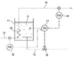
図1は温水式液化ガス気化装置に本発明を適用した一形態例を示す系統図、図2は制御手順の一例を示すフローチャートである。 FIG. 1 is a system diagram showing an embodiment in which the present invention is applied to a hot water type liquefied gas vaporizer, and FIG. 2 is a flowchart showing an example of a control procedure.
まず、温水式液化ガス気化装置は、温水Hを貯留する温水槽11と、該温水槽11内に気密状態で配設された熱交換部12と、該熱交換部12に低温液化ガスを供給する低温液化ガス供給配管13と、熱交換部12で気化した製品ガスを使用先に送出する製品ガス送出配管14と、温水槽11の温水中に高温、高圧のスチームを供給するスチーム供給配管15と、該スチーム供給配管15のスチーム供給量を調節するためのスチーム供給弁16と、該スチーム供給弁16を温水槽11の温水Hの温度測定値に基づいて開閉制御する温度指示調節計(TIC)17と、該温度指示調節計17の制御手順を、製品ガス送出配管14を流れる製品ガスの流量測定値に基づいて切り替えるための信号を出力する製品ガス流量計(FIS)18とを備えている。
First, the hot water liquefied gas vaporizer supplies a
温度指示調節計17によるスチーム供給弁16の制御は、従来から一般に行われている通常のPID制御、すなわち、温度指示調節計17で測定した温水Hの温度測定値に基づいて温水Hの水温を一定乃至一定範囲内に維持するようにスチーム供給弁16の開度を自動調節する制御と、製品ガス流量計18で測定した流量測定値があらかじめ設定された流量最小値を下回ったときに製品ガス流量計18から出力される信号によって切り替えられるスチーム供給弁16の開閉(ON−OFF)制御とで行われる。
The
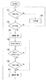
図2において、まず、ステップ101で製品ガス流量計18で測定した流量測定値FGと、あらかじめ設定されている流量最小値FSとの比較が行われる。このステップ101で流量測定値FGが流量最小値FS未満と判断された場合(Yes)は、ステップ102に進み、温度指示調節計17で測定した温度測定値HCと、あらかじめ設定されている水温最小値HLとの比較が行われる。
In FIG. 2, first, the flow rate measurement value FG measured by the product
このステップ102で温度測定値HCが水温最小値HL未満であると判断された場合(Yes)は、ステップ103に進んでスチーム供給弁16があらかじめ規定された弁開度(規定弁開度)になるように制御され、続けてステップ104に進んでタイマーがスタートしてカウントを開始し、さらに、ステップ105でタイマーがタイムアップしたか否かが判断される。
When it is determined in
ステップ105でタイマーがタイムアップしたと判断されたら(Yes)、ステップ106に進み、温度指示調節計17で測定した温度測定値HCと、あらかじめ設定されている水温最大値HHとの比較が行われる。ステップ106で温度測定値HCが水温最大値HH未満の場合は(No)、温度測定値HCが水温最大値HH以上になるまでステップ106が繰り返され、温度測定値HCが水温最大値HH以上になったと判断されたときに(Yes)、ステップ107に進んでスチーム供給弁16を閉じて全閉状態とした後、最初のステップ101に戻る。
If it is determined in
また、ステップ102で温度測定値HCが水温最小値HL以上であると判断された場合(No)は、ステップ107に進み、スチーム供給弁16を閉じた後、最初のステップ101に戻る。さらに、ステップ101で流量測定値FGが流量最小値FS以上と判断された場合(No)は、ステップ108に進んで通常のPID制御が行われ、水温が低いときにはスチーム供給弁16を開方向に、水温が高いときにはスチーム供給弁16を閉方向に、それぞれ調節する制御が行われてステップ101に戻る。
If it is determined in
この制御における各種設定値は、装置の規模、例えば、水槽の容積、製品ガスの最大送出量、スチームの最大供給量等の条件に応じて適宜設定されるものであって、さらに、スチーム供給弁16には、このスチーム供給弁16における弁シートや弁座部にエロージョンが発生したり、ストレーナを通過した微小な異物が食い込んだりすることがない最小弁開度が設定されており、PID制御によってスチーム供給弁16を開閉制御するときには、この最小弁開度が適用され、この最小弁開度以上に弁開度を絞る必要が生じたときには、スチーム供給弁16を閉じるように設定している。
The various set values in this control are appropriately set according to conditions such as the scale of the apparatus, for example, the volume of the water tank, the maximum delivery amount of product gas, the maximum supply amount of steam, and the
例えば、最小弁開度を30%に設定したときには、弁開度が30〜100%の間でPID制御を行い、温水の温度が弁開度を30%未満にするような状態になったときには、スチーム供給弁16を一時的に全閉状態とし、弁開度が0〜30%の範囲にならないようにする。
For example, when the minimum valve opening is set to 30%, PID control is performed when the valve opening is between 30 and 100%, and when the temperature of the hot water makes the valve opening less than 30% The
ステップ103におけるスチーム供給弁16の規定弁開度や、ステップ105におけるタイマー等のパラメーターは、系の熱収支を計算して決定され、規定弁開度は、前記最小弁開度以上で、前記ステップ106を繰り返す際に、水温を適当な速度で上昇させることが可能な開度に設定すればよく、例えば、50〜60%程度に設定しておけばよい。
Parameters such as the specified valve opening of the
このように、製品ガス流量計18で測定した製品ガスの流量測定値FGがあらかじめ設定した最小流量値FS以上のときには、温度指示調節計17による通常のPID制御でスチーム供給弁16の弁開度を制御し、所定温度に加温した温水Hで低温液化ガスを加温するように設定することにより、今までと同様にして所定温度の製品ガスを使用先に供給することができる。このとき、前記最小弁開度以上の範囲でスチーム供給弁16の弁開度を制御することにより、弁シートや弁座部にエロージョンが発生したり、微小な異物が食い込んだりすることも防止できる。
Thus, when the product gas flow rate measurement value FG measured by the product
そして、使用先での製品ガスの使用量が極端に少なくなったり、製品ガスの使用が中断されたりして、製品ガス流量計18で測定した製品ガスの流量測定値FGがあらかじめ設定した最小流量値FSを下回る状態となったときには、製品ガス流量計18からの信号により、温度指示調節計17のPID制御を中断してスチーム供給弁16の開閉制御を行う。これにより、スチーム供給弁16が微開−閉を繰り返す状態になることを回避できるので、弁シートや弁座部にエロージョンが発生したり、微小な異物が食い込んだりすることがなくなる。
The product gas flow rate measured value FG measured by the product
また、スチーム供給弁16の開閉制御を行うにあたり、温水Hの温度測定値HCが水温最小値HL以上の場合は(ステップ102でNo)、スチーム供給弁16を閉じてスチームの供給を遮断することにより、温水Hを無駄に加熱することなく、エネルギーの節約が図れる。さらに、ステップ102での水温最小値HLをPID制御での低温側設定値よりも低い温度に設定しておくことにより、PID制御から開閉制御に移行した直後は、温度測定値HCが水温最小値HL以上となっているので、ステップ107でスチーム供給弁16を閉じるだけの操作でよく、さらに、ステップ106での水温最大値HHをPID制御での高温側設定値よりも高い温度に設定しておくことにより、開閉制御からPID制御に移行した直後は、スチーム供給弁16が全閉状態での制御が継続されることになり、制御性を向上させることができる。しかも、開閉制御の際に、ステップ105でタイマーにより所定時間継続してスチーム供給弁16を規定開度に保つようにしたことにより、スチーム供給弁16の頻繁な開閉動作を回避することができる。
Further, when performing the opening / closing control of the
なお、本形態例では、製品ガス流量計18で測定した製品ガスの流量に応じて制御方式を切り替えるようにしているが、図1に想像線で示すように、低温液化ガス供給配管13に液化ガス流量計19を設け、この液化ガス流量計19で装置に供給される低温液化ガスの流量を測定し、この流量測定値に応じて制御方式を切り替えることもできる。
In this embodiment, the control method is switched according to the flow rate of the product gas measured by the product
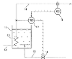
図3は温水式液化ガス気化装置に本発明を適用した他の形態例を示す系統図である。なお、以下の説明において、前記形態例で示した液化ガス気化装置における構成要素と同一の構成要素には、それぞれ同一符号を付して詳細な説明は省略する。 FIG. 3 is a system diagram showing another embodiment in which the present invention is applied to a hot water type liquefied gas vaporizer. In the following description, the same components as those in the liquefied gas vaporizer shown in the above-described embodiment are given the same reference numerals, and detailed description thereof is omitted.
この温水式液化ガス気化装置は、温度指示調節計17によるPID制御を、前述の温水Hの温度に代えて、熱交換部12で気化した製品ガスの温度測定値に基づいて行うようにしている。この場合も、図2に示したステップ108でのPID制御の他は、製品ガス流量計18で測定した流量測定値FGに基づいて前記ステップ101〜107の開閉制御に切り替えることにより、前記同様の運転制御を行うことができる。
In this hot water type liquefied gas vaporizer, PID control by the
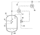
図4はスチーム式液化ガス気化装置に本発明を適用した一形態例を示す系統図である。このスチーム式液化ガス気化装置は、スチームが導入される密閉容器21内に熱交換部12を設けたもので、密閉容器21の底部にはドレン排出部22が設けられている。
FIG. 4 is a system diagram showing an embodiment in which the present invention is applied to a steam type liquefied gas vaporizer. This steam type liquefied gas vaporizer is provided with a
このようなスチーム式液化ガス気化装置においても、熱交換部12で気化した製品ガスの温度測定値に基づいてPID制御を行い、製品ガス流量計18で測定した流量測定値FGに基づいてPID制御を前記開閉制御に切り替えることにより、前記同様の安定した運転制御を行うことができる。
Also in such a steam type liquefied gas vaporizer, PID control is performed based on the temperature measurement value of the product gas vaporized in the
なお、図3及び図4に示す形態例では、製品ガスの送出が完全に止まった場合、すなわち、製品ガス流量計18あるいは液化ガス流量計(図示せず)の流量測定値がゼロになった場合には、スチーム供給弁16を閉じ状態とし、装置へのスチームの供給を停止して待機状態とすればよい。
3 and 4, when the delivery of the product gas is completely stopped, that is, the flow rate measurement value of the product
11…温水槽、12…熱交換部、13…低温液化ガス供給配管、14…製品ガス送出配管、15…スチーム供給配管、16…スチーム供給弁、17…温度指示調節計、18…製品ガス流量計、19…液化ガス流量計、21…密閉容器、22…ドレン排出部
DESCRIPTION OF
Claims (4)
Priority Applications (1)
| Application Number | Priority Date | Filing Date | Title |
|---|---|---|---|
| JP2004105952A JP4567358B2 (en) | 2004-03-31 | 2004-03-31 | Operation method of liquefied gas vaporizer |
Applications Claiming Priority (1)
| Application Number | Priority Date | Filing Date | Title |
|---|---|---|---|
| JP2004105952A JP4567358B2 (en) | 2004-03-31 | 2004-03-31 | Operation method of liquefied gas vaporizer |
Publications (2)
| Publication Number | Publication Date |
|---|---|
| JP2005291324A true JP2005291324A (en) | 2005-10-20 |
| JP4567358B2 JP4567358B2 (en) | 2010-10-20 |
Family
ID=35324487
Family Applications (1)
| Application Number | Title | Priority Date | Filing Date |
|---|---|---|---|
| JP2004105952A Expired - Lifetime JP4567358B2 (en) | 2004-03-31 | 2004-03-31 | Operation method of liquefied gas vaporizer |
Country Status (1)
| Country | Link |
|---|---|
| JP (1) | JP4567358B2 (en) |
Cited By (3)
| Publication number | Priority date | Publication date | Assignee | Title |
|---|---|---|---|---|
| KR100890436B1 (en) | 2007-04-13 | 2009-03-26 | 한국가스안전공사 | Carburetor design device and its design method |
| KR20150037268A (en) * | 2013-09-30 | 2015-04-08 | 한국전력공사 | Liquefied gas container with heating system using external air |
| JP2019178686A (en) * | 2018-03-30 | 2019-10-17 | 大陽日酸株式会社 | Method for operating liquefied gas vaporizer |
Citations (3)
| Publication number | Priority date | Publication date | Assignee | Title |
|---|---|---|---|---|
| JPH06257586A (en) * | 1993-03-09 | 1994-09-13 | Mitsubishi Heavy Ind Ltd | Method for controlling oil level in gas-liquid separation tank |
| JPH06265209A (en) * | 1991-03-06 | 1994-09-20 | Tokyo Gas Co Ltd | Control method of decompression boiler type vaporizer |
| JP2002340297A (en) * | 2001-05-18 | 2002-11-27 | Nippon Sanso Corp | High pressure gas supply equipment |
-
2004
- 2004-03-31 JP JP2004105952A patent/JP4567358B2/en not_active Expired - Lifetime
Patent Citations (3)
| Publication number | Priority date | Publication date | Assignee | Title |
|---|---|---|---|---|
| JPH06265209A (en) * | 1991-03-06 | 1994-09-20 | Tokyo Gas Co Ltd | Control method of decompression boiler type vaporizer |
| JPH06257586A (en) * | 1993-03-09 | 1994-09-13 | Mitsubishi Heavy Ind Ltd | Method for controlling oil level in gas-liquid separation tank |
| JP2002340297A (en) * | 2001-05-18 | 2002-11-27 | Nippon Sanso Corp | High pressure gas supply equipment |
Cited By (4)
| Publication number | Priority date | Publication date | Assignee | Title |
|---|---|---|---|---|
| KR100890436B1 (en) | 2007-04-13 | 2009-03-26 | 한국가스안전공사 | Carburetor design device and its design method |
| KR20150037268A (en) * | 2013-09-30 | 2015-04-08 | 한국전력공사 | Liquefied gas container with heating system using external air |
| KR102096520B1 (en) * | 2013-09-30 | 2020-05-27 | 한국전력공사 | Liquefied gas container with heating system using external air |
| JP2019178686A (en) * | 2018-03-30 | 2019-10-17 | 大陽日酸株式会社 | Method for operating liquefied gas vaporizer |
Also Published As
| Publication number | Publication date |
|---|---|
| JP4567358B2 (en) | 2010-10-20 |
Similar Documents
| Publication | Publication Date | Title |
|---|---|---|
| JP2012047234A (en) | Gas filling device | |
| JP4327559B2 (en) | Fuel filling method | |
| JP4567358B2 (en) | Operation method of liquefied gas vaporizer | |
| JP4286186B2 (en) | Cogeneration system and operation control method thereof | |
| JP2004301186A (en) | Liquefied gas vaporization system | |
| JP4906464B2 (en) | Hot water system | |
| JP2004036980A (en) | Hot-water supply system | |
| CN209926016U (en) | Water bath vaporization system | |
| JP7622477B2 (en) | Thermal storage system | |
| JP4917417B2 (en) | Cogeneration system | |
| JP3699402B2 (en) | Hot water mixing unit | |
| JPS6229791Y2 (en) | ||
| JP2003214597A (en) | Hydrogen supply device using LNG | |
| JPH09101059A (en) | Hot water supply system | |
| JP4076939B2 (en) | Hot water system | |
| JP3701903B2 (en) | Hot water mixing unit for water heater | |
| JP2004116932A (en) | Hot water heating heat source machine | |
| JP4354074B2 (en) | Deaerator seal steam system equipment | |
| JP7382811B2 (en) | Heat exchanger | |
| JP3834412B2 (en) | Combustion equipment | |
| JP2001141302A (en) | Latent heat recovery type hot water supply apparatus | |
| JP2005291627A (en) | Hot water supply system | |
| JPH09145004A (en) | Controller for emergency stop of pressurized fluidized bed boiler | |
| JP2710124B2 (en) | Pure water supply control device for fuel cell steam separator | |
| JP2710125B2 (en) | Control device for excess steam in steam separator of fuel cell |
Legal Events
| Date | Code | Title | Description |
|---|---|---|---|
| A621 | Written request for application examination |
Free format text: JAPANESE INTERMEDIATE CODE: A621 Effective date: 20070314 |
|
| A977 | Report on retrieval |
Free format text: JAPANESE INTERMEDIATE CODE: A971007 Effective date: 20100325 |
|
| A131 | Notification of reasons for refusal |
Free format text: JAPANESE INTERMEDIATE CODE: A131 Effective date: 20100406 |
|
| A521 | Request for written amendment filed |
Free format text: JAPANESE INTERMEDIATE CODE: A523 Effective date: 20100603 |
|
| TRDD | Decision of grant or rejection written | ||
| A01 | Written decision to grant a patent or to grant a registration (utility model) |
Free format text: JAPANESE INTERMEDIATE CODE: A01 Effective date: 20100713 |
|
| A01 | Written decision to grant a patent or to grant a registration (utility model) |
Free format text: JAPANESE INTERMEDIATE CODE: A01 |
|
| A61 | First payment of annual fees (during grant procedure) |
Free format text: JAPANESE INTERMEDIATE CODE: A61 Effective date: 20100805 |
|
| R150 | Certificate of patent or registration of utility model |
Ref document number: 4567358 Country of ref document: JP Free format text: JAPANESE INTERMEDIATE CODE: R150 Free format text: JAPANESE INTERMEDIATE CODE: R150 |
|
| FPAY | Renewal fee payment (event date is renewal date of database) |
Free format text: PAYMENT UNTIL: 20130813 Year of fee payment: 3 |
|
| FPAY | Renewal fee payment (event date is renewal date of database) |
Free format text: PAYMENT UNTIL: 20130813 Year of fee payment: 3 |
|
| FPAY | Renewal fee payment (event date is renewal date of database) |
Free format text: PAYMENT UNTIL: 20130813 Year of fee payment: 3 |
|
| R250 | Receipt of annual fees |
Free format text: JAPANESE INTERMEDIATE CODE: R250 |
|
| R250 | Receipt of annual fees |
Free format text: JAPANESE INTERMEDIATE CODE: R250 |
|
| R250 | Receipt of annual fees |
Free format text: JAPANESE INTERMEDIATE CODE: R250 |
|
| R250 | Receipt of annual fees |
Free format text: JAPANESE INTERMEDIATE CODE: R250 |
|
| R250 | Receipt of annual fees |
Free format text: JAPANESE INTERMEDIATE CODE: R250 |
|
| R250 | Receipt of annual fees |
Free format text: JAPANESE INTERMEDIATE CODE: R250 |
|
| R250 | Receipt of annual fees |
Free format text: JAPANESE INTERMEDIATE CODE: R250 |
|
| R250 | Receipt of annual fees |
Free format text: JAPANESE INTERMEDIATE CODE: R250 |
|
| S111 | Request for change of ownership or part of ownership |
Free format text: JAPANESE INTERMEDIATE CODE: R313111 |
|
| R350 | Written notification of registration of transfer |
Free format text: JAPANESE INTERMEDIATE CODE: R350 |
|
| R250 | Receipt of annual fees |
Free format text: JAPANESE INTERMEDIATE CODE: R250 |
|
| R250 | Receipt of annual fees |
Free format text: JAPANESE INTERMEDIATE CODE: R250 |
|
| R250 | Receipt of annual fees |
Free format text: JAPANESE INTERMEDIATE CODE: R250 |
|
| EXPY | Cancellation because of completion of term |