JP2005291287A - センサ付転がり軸受 - Google Patents
センサ付転がり軸受 Download PDFInfo
- Publication number
- JP2005291287A JP2005291287A JP2004104666A JP2004104666A JP2005291287A JP 2005291287 A JP2005291287 A JP 2005291287A JP 2004104666 A JP2004104666 A JP 2004104666A JP 2004104666 A JP2004104666 A JP 2004104666A JP 2005291287 A JP2005291287 A JP 2005291287A
- Authority
- JP
- Japan
- Prior art keywords
- rolling bearing
- resistor
- sensor
- ring
- raceway surface
- Prior art date
- Legal status (The legal status is an assumption and is not a legal conclusion. Google has not performed a legal analysis and makes no representation as to the accuracy of the status listed.)
- Pending
Links
- 238000005096 rolling process Methods 0.000 title claims abstract description 109
- 239000012212 insulator Substances 0.000 claims description 31
- 239000000463 material Substances 0.000 claims description 15
- 239000004593 Epoxy Substances 0.000 claims description 10
- 239000002923 metal particle Substances 0.000 claims description 10
- 239000004734 Polyphenylene sulfide Substances 0.000 claims description 9
- 229920000069 polyphenylene sulfide Polymers 0.000 claims description 9
- 238000009413 insulation Methods 0.000 abstract 1
- 230000002093 peripheral effect Effects 0.000 description 9
- ZOKXTWBITQBERF-UHFFFAOYSA-N Molybdenum Chemical compound [Mo] ZOKXTWBITQBERF-UHFFFAOYSA-N 0.000 description 6
- 229910052750 molybdenum Inorganic materials 0.000 description 6
- 239000011733 molybdenum Substances 0.000 description 6
- 230000000694 effects Effects 0.000 description 4
- 230000005611 electricity Effects 0.000 description 4
- 239000000314 lubricant Substances 0.000 description 4
- 230000007423 decrease Effects 0.000 description 3
- 238000000034 method Methods 0.000 description 3
- 229920000265 Polyparaphenylene Polymers 0.000 description 2
- UCKMPCXJQFINFW-UHFFFAOYSA-N Sulphide Chemical compound [S-2] UCKMPCXJQFINFW-UHFFFAOYSA-N 0.000 description 2
- 238000005299 abrasion Methods 0.000 description 2
- 238000009429 electrical wiring Methods 0.000 description 2
- 230000004048 modification Effects 0.000 description 2
- 238000012986 modification Methods 0.000 description 2
- -1 polyphenylene Polymers 0.000 description 2
- 238000010586 diagram Methods 0.000 description 1
- 239000011810 insulating material Substances 0.000 description 1
- 238000005259 measurement Methods 0.000 description 1
- 230000035515 penetration Effects 0.000 description 1
- 230000000630 rising effect Effects 0.000 description 1
Images

Classifications
-
- F—MECHANICAL ENGINEERING; LIGHTING; HEATING; WEAPONS; BLASTING
- F16—ENGINEERING ELEMENTS AND UNITS; GENERAL MEASURES FOR PRODUCING AND MAINTAINING EFFECTIVE FUNCTIONING OF MACHINES OR INSTALLATIONS; THERMAL INSULATION IN GENERAL
- F16C—SHAFTS; FLEXIBLE SHAFTS; ELEMENTS OR CRANKSHAFT MECHANISMS; ROTARY BODIES OTHER THAN GEARING ELEMENTS; BEARINGS
- F16C19/00—Bearings with rolling contact, for exclusively rotary movement
- F16C19/22—Bearings with rolling contact, for exclusively rotary movement with bearing rollers essentially of the same size in one or more circular rows, e.g. needle bearings
- F16C19/24—Bearings with rolling contact, for exclusively rotary movement with bearing rollers essentially of the same size in one or more circular rows, e.g. needle bearings for radial load mainly
- F16C19/26—Bearings with rolling contact, for exclusively rotary movement with bearing rollers essentially of the same size in one or more circular rows, e.g. needle bearings for radial load mainly with a single row of rollers
Landscapes
- Engineering & Computer Science (AREA)
- General Engineering & Computer Science (AREA)
- Mechanical Engineering (AREA)
- Rolling Contact Bearings (AREA)
- Length Measuring Devices With Unspecified Measuring Means (AREA)
Abstract
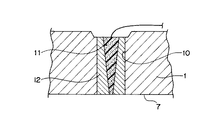
【解決手段】 外輪1に、径方向に延びて外輪1の軌道面7に開口する貫通穴10を形成する。また、上記貫通穴10に、略貫通穴10の中心軸の方向に延びる棒状の抵抗体11と、この抵抗体11と貫通穴10の内面との間に配置されて、抵抗体11と外輪1とが電気接続することを防止する絶縁体12とを配置する。
【選択図】 図1
Description
第1の軌道面を有する第1の軌道輪と、
第2の軌道面を有する第2の軌道輪と、
上記第1の軌道面と上記第2の軌道面との間に配置された転動体と
を備え、
上記第1の軌道輪には、上記第1の軌道面に開口した貫通穴が形成され、
上記貫通穴には、略上記貫通穴の中心軸の方向に延びる棒状の抵抗体と、上記抵抗体と上記第1の軌道輪とが電気接続されることを防止する絶縁体とが配置されていることを特徴としている。
図1は、この発明の第1実施形態のセンサ付転がり軸受の軸方向の断面図である。
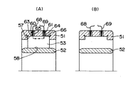
図4は、第2実施形態のセンサ付転がり軸受の軸方向の断面図である。
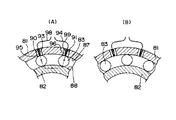
図5は、第3実施形態のセンサ付転がり軸受の径方向の断面図である。
2,52,82 内輪
3,53 円筒ころ
7,8,57,58 軌道面
10,60,61,90,91 貫通穴
11,63,64,93,94 抵抗体
12,65,66,95,96 絶縁体
83 玉
87,88 軌道溝
Claims (8)
- 第1の軌道面を有する第1の軌道輪と、
第2の軌道面を有する第2の軌道輪と、
上記第1の軌道面と上記第2の軌道面との間に配置された転動体と
を備え、
上記第1の軌道輪には、上記第1の軌道面に開口した貫通穴が形成され、
上記貫通穴には、略上記貫通穴の中心軸の方向に延びる棒状の抵抗体と、上記抵抗体と上記第1の軌道輪とが電気接続されることを防止する絶縁体とが配置されていることを特徴とするセンサ付転がり軸受。 - 請求項1に記載のセンサ付転がり軸受において、
上記抵抗体は、上記第1の軌道面に向けて先細りになっていることを特徴とするセンサ付転がり軸受。 - 請求項1または2に記載のセンサ転がり軸受において、
上記抵抗体は、潤滑性を有していることを特徴とするセンサ付転がり軸受。 - 請求項1乃至3のいずれか1つに記載のセンサ付転がり軸受において、
上記絶縁体は、潤滑性を有していることを特徴とするセンサ付転がり軸受。 - 請求項1または2に記載のセンサ付転がり軸受において、
上記抵抗体は、エポキシに金属粒子を分散した材料から構成され、上記絶縁体は、ポリフェニレンサルファイドから構成されていることを特徴とするセンサ付転がり軸受。 - 請求項1乃至5のいずれか1つに記載のセンサ付転がり軸受において、
上記第1の軌道輪は、固定輪であることを特徴とするセンサ付転がり軸受。 - 請求項1乃至6のいずれか1つに記載のセンサ付転がり軸受において、
上記転動体は、円筒ころまたは円錐ころであり、上記貫通穴は、上記第1の軌道輪に軸方向に間隔を置いて2つ形成されていることを特徴とするセンサ付転がり軸受。 - 請求項1乃至6のいずれか1つに記載のセンサ付転がり軸受において、
上記貫通穴は、上記第1の軌道輪に周方向に間隔を置いて2つ形成されていることを特徴とするセンサ付転がり軸受。
Priority Applications (1)
| Application Number | Priority Date | Filing Date | Title |
|---|---|---|---|
| JP2004104666A JP2005291287A (ja) | 2004-03-31 | 2004-03-31 | センサ付転がり軸受 |
Applications Claiming Priority (1)
| Application Number | Priority Date | Filing Date | Title |
|---|---|---|---|
| JP2004104666A JP2005291287A (ja) | 2004-03-31 | 2004-03-31 | センサ付転がり軸受 |
Publications (2)
| Publication Number | Publication Date |
|---|---|
| JP2005291287A true JP2005291287A (ja) | 2005-10-20 |
| JP2005291287A5 JP2005291287A5 (ja) | 2007-04-19 |
Family
ID=35324458
Family Applications (1)
| Application Number | Title | Priority Date | Filing Date |
|---|---|---|---|
| JP2004104666A Pending JP2005291287A (ja) | 2004-03-31 | 2004-03-31 | センサ付転がり軸受 |
Country Status (1)
| Country | Link |
|---|---|
| JP (1) | JP2005291287A (ja) |
Cited By (2)
| Publication number | Priority date | Publication date | Assignee | Title |
|---|---|---|---|---|
| CN105122025A (zh) * | 2012-12-14 | 2015-12-02 | Skf公司 | 光纤传感器组件 |
| JPWO2023166567A1 (ja) * | 2022-03-01 | 2023-09-07 |
-
2004
- 2004-03-31 JP JP2004104666A patent/JP2005291287A/ja active Pending
Cited By (4)
| Publication number | Priority date | Publication date | Assignee | Title |
|---|---|---|---|---|
| CN105122025A (zh) * | 2012-12-14 | 2015-12-02 | Skf公司 | 光纤传感器组件 |
| JPWO2023166567A1 (ja) * | 2022-03-01 | 2023-09-07 | ||
| WO2023166567A1 (ja) * | 2022-03-01 | 2023-09-07 | 三菱電機株式会社 | 転がり軸受の異常検知装置、転がり軸受の異常診断装置、列車異常監視システム及び転がり軸受の異常診断方法 |
| JP7471523B2 (ja) | 2022-03-01 | 2024-04-19 | 三菱電機株式会社 | 転がり軸受の異常検知装置、転がり軸受の異常診断装置、及び列車異常監視システム |
Similar Documents
| Publication | Publication Date | Title |
|---|---|---|
| US9464672B2 (en) | Rolling bearing with integrated electrical shunt | |
| KR101428829B1 (ko) | 센서식 베어링 유닛 | |
| US9581203B2 (en) | Shunt bearing with insulating coating | |
| ES2219827T3 (es) | Dispositivo de medicion del desgaste para rodamientos grandes. | |
| CN105518322B (zh) | 滚动轴承装置 | |
| EP2955395B1 (en) | Electrically conductive bearing system and manufacturing method | |
| CN113302411B (zh) | 滚动装置的诊断方法 | |
| JPH0961268A (ja) | 軸受用荷重測定装置 | |
| US20120068575A1 (en) | Rotatable antifriction bearing | |
| US7071834B2 (en) | Device for monitoring the operating conditions of rolling bearing | |
| US9933018B2 (en) | Bearing with condition monitoring sensor | |
| JP2005291287A (ja) | センサ付転がり軸受 | |
| US9644684B2 (en) | Capacitance measurement in a bearing housing | |
| CN112815000A (zh) | 一种轴承组件、具有轴承组件的装置 | |
| JP6047963B2 (ja) | 転がり軸受の予圧測定方法 | |
| US11226005B2 (en) | Bearing arrangements, and module carrier for them | |
| JP2007298527A (ja) | 主軸支持装置 | |
| JP2008196956A (ja) | センサ付き軸受及びその製造方法 | |
| JP3959730B2 (ja) | 転がり軸受 | |
| JP2008026216A (ja) | 転がり軸受の内輪温度測定装置 | |
| JPH10184705A (ja) | 軸受の給脂装置 | |
| JP2020106145A (ja) | シール付き軸受 | |
| JP2008064183A (ja) | 軸受装置 | |
| JP2000291667A (ja) | 軸受装置 | |
| JP7045227B2 (ja) | ベアリングの製造方法 |
Legal Events
| Date | Code | Title | Description |
|---|---|---|---|
| A521 | Written amendment |
Free format text: JAPANESE INTERMEDIATE CODE: A523 Effective date: 20070306 |
|
| A621 | Written request for application examination |
Free format text: JAPANESE INTERMEDIATE CODE: A621 Effective date: 20070306 |
|
| A977 | Report on retrieval |
Free format text: JAPANESE INTERMEDIATE CODE: A971007 Effective date: 20090402 |
|
| A131 | Notification of reasons for refusal |
Free format text: JAPANESE INTERMEDIATE CODE: A131 Effective date: 20090924 |
|
| RD04 | Notification of resignation of power of attorney |
Free format text: JAPANESE INTERMEDIATE CODE: A7424 Effective date: 20091225 |
|
| A02 | Decision of refusal |
Free format text: JAPANESE INTERMEDIATE CODE: A02 Effective date: 20100209 |