JP2005291287A - Rolling bearing with sensor - Google Patents
Rolling bearing with sensor Download PDFInfo
- Publication number
- JP2005291287A JP2005291287A JP2004104666A JP2004104666A JP2005291287A JP 2005291287 A JP2005291287 A JP 2005291287A JP 2004104666 A JP2004104666 A JP 2004104666A JP 2004104666 A JP2004104666 A JP 2004104666A JP 2005291287 A JP2005291287 A JP 2005291287A
- Authority
- JP
- Japan
- Prior art keywords
- rolling bearing
- resistor
- sensor
- ring
- raceway surface
- Prior art date
- Legal status (The legal status is an assumption and is not a legal conclusion. Google has not performed a legal analysis and makes no representation as to the accuracy of the status listed.)
- Pending
Links
- 238000005096 rolling process Methods 0.000 title claims abstract description 109
- 239000012212 insulator Substances 0.000 claims description 31
- 239000000463 material Substances 0.000 claims description 15
- 239000004593 Epoxy Substances 0.000 claims description 10
- 239000002923 metal particle Substances 0.000 claims description 10
- 239000004734 Polyphenylene sulfide Substances 0.000 claims description 9
- 229920000069 polyphenylene sulfide Polymers 0.000 claims description 9
- 238000009413 insulation Methods 0.000 abstract 1
- 230000002093 peripheral effect Effects 0.000 description 9
- ZOKXTWBITQBERF-UHFFFAOYSA-N Molybdenum Chemical compound [Mo] ZOKXTWBITQBERF-UHFFFAOYSA-N 0.000 description 6
- 229910052750 molybdenum Inorganic materials 0.000 description 6
- 239000011733 molybdenum Substances 0.000 description 6
- 230000000694 effects Effects 0.000 description 4
- 230000005611 electricity Effects 0.000 description 4
- 239000000314 lubricant Substances 0.000 description 4
- 230000007423 decrease Effects 0.000 description 3
- 238000000034 method Methods 0.000 description 3
- 229920000265 Polyparaphenylene Polymers 0.000 description 2
- UCKMPCXJQFINFW-UHFFFAOYSA-N Sulphide Chemical compound [S-2] UCKMPCXJQFINFW-UHFFFAOYSA-N 0.000 description 2
- 238000005299 abrasion Methods 0.000 description 2
- 238000009429 electrical wiring Methods 0.000 description 2
- 230000004048 modification Effects 0.000 description 2
- 238000012986 modification Methods 0.000 description 2
- -1 polyphenylene Polymers 0.000 description 2
- 238000010586 diagram Methods 0.000 description 1
- 239000011810 insulating material Substances 0.000 description 1
- 238000005259 measurement Methods 0.000 description 1
- 230000035515 penetration Effects 0.000 description 1
- 230000000630 rising effect Effects 0.000 description 1
Images

Classifications
-
- F—MECHANICAL ENGINEERING; LIGHTING; HEATING; WEAPONS; BLASTING
- F16—ENGINEERING ELEMENTS AND UNITS; GENERAL MEASURES FOR PRODUCING AND MAINTAINING EFFECTIVE FUNCTIONING OF MACHINES OR INSTALLATIONS; THERMAL INSULATION IN GENERAL
- F16C—SHAFTS; FLEXIBLE SHAFTS; ELEMENTS OR CRANKSHAFT MECHANISMS; ROTARY BODIES OTHER THAN GEARING ELEMENTS; BEARINGS
- F16C19/00—Bearings with rolling contact, for exclusively rotary movement
- F16C19/22—Bearings with rolling contact, for exclusively rotary movement with bearing rollers essentially of the same size in one or more circular rows, e.g. needle bearings
- F16C19/24—Bearings with rolling contact, for exclusively rotary movement with bearing rollers essentially of the same size in one or more circular rows, e.g. needle bearings for radial load mainly
- F16C19/26—Bearings with rolling contact, for exclusively rotary movement with bearing rollers essentially of the same size in one or more circular rows, e.g. needle bearings for radial load mainly with a single row of rollers
Landscapes
- Engineering & Computer Science (AREA)
- General Engineering & Computer Science (AREA)
- Mechanical Engineering (AREA)
- Length Measuring Devices With Unspecified Measuring Means (AREA)
- Rolling Contact Bearings (AREA)
Abstract
Description
本発明は、軌道輪の摩耗の度合いを判定できるセンサ付転がり軸受に関する。 The present invention relates to a sensor-equipped rolling bearing capable of determining the degree of wear of a bearing ring.
従来、軌道輪の摩耗の度合いを判定できるセンサ付転がり軸受としては、特開平11−148803号公報(特許文献1)に記載されているものがある。 Conventionally, as a sensor-equipped rolling bearing capable of determining the degree of wear of a bearing ring, there is one described in JP-A-11-148803 (Patent Document 1).
このセンサ付転がり軸受は、外輪と、内輪と、円筒ころとを備える。上記内輪は、外周に形成された軌道面の両側に上記円筒ころの端面と摺接する略リング状の二つの環状鍔部を有している。上記二つの環状鍔部は、略同一形状であり、各環状鍔部の軸方向の厚さは、略同一になっている。 This sensor-equipped rolling bearing includes an outer ring, an inner ring, and a cylindrical roller. The inner ring has two substantially ring-shaped annular flanges that are in sliding contact with the end surfaces of the cylindrical rollers on both sides of the raceway surface formed on the outer periphery. The two annular flanges have substantially the same shape, and the axial thickness of each annular flange is substantially the same.
上記環状鍔部の片方には、一つの切欠きが形成されている。上記切欠きは、周方向に一定幅を有すると共に、径方向に一定深さを有している。また、上記切欠きは、軸方向において、上記環状鍔部の一端面から他端面まで上記環状鍔部を貫くように延びている。 One notch is formed on one side of the annular flange. The notch has a certain width in the circumferential direction and a certain depth in the radial direction. Moreover, the said notch is extended in the axial direction so that the said annular collar part may be penetrated from the one end surface of the said annular collar part to an other end surface.
上記切欠きの表面全域には、略一定の厚さを有する絶縁膜が形成されており、この絶縁膜上には、略U字形状の配線が、その開口部が軸方向の外方を向くように配置されている。詳細には、上記配線は、その配線のU字の底に当たる部分が、絶縁膜上の上記円筒ころ側の周囲部分に上記周方向の幅全域に亘って走っている。すなわち、上記配線は、上記U字の底の部分が上記円筒ころに接触するように、上記絶縁膜上に配置されている。上記U字の底の部分は、上記鍔部の摺動面の摩耗が許容の範囲外まで進んだとき、上記限度を超えた機械的な摩耗によって、断線するようになっている。 An insulating film having a substantially constant thickness is formed over the entire surface of the notch, and a substantially U-shaped wiring is formed on the insulating film with the opening facing outward in the axial direction. Are arranged as follows. Specifically, in the wiring, a portion corresponding to the bottom of the U-shape of the wiring runs across the entire width in the circumferential direction on a peripheral portion on the cylindrical roller side on the insulating film. That is, the wiring is disposed on the insulating film so that the bottom portion of the U-shape contacts the cylindrical roller. When the wear of the sliding surface of the flange portion goes beyond an allowable range, the bottom portion of the U-shape is disconnected due to mechanical wear exceeding the above limit.
上記従来のセンサ付転がり軸受は、上記U字状の配線の両端部が電気的に接続されている場合、上記鍔部の摺動面の摩耗が許容の範囲内であることを判断する一方、上記U字状の配線の両端部が電気的に切断されている場合、上記底の部分が機械的に切断されたと判断して、上記鍔部の摺動面の摩耗が許容の範囲外まで進んだと判断するようになっている。 In the conventional rolling bearing with sensor, when both ends of the U-shaped wiring are electrically connected, it is determined that the wear of the sliding surface of the flange is within an allowable range, If both ends of the U-shaped wiring are electrically cut, it is determined that the bottom portion has been mechanically cut, and the wear of the sliding surface of the collar portion proceeds beyond the allowable range. It comes to judge that.
しかしながら、上記従来のセンサ付転がり軸受では、摩耗の度合いの判断基準が、配線の電気的(機械的)な接続または切断を判断するだけであるので、摩耗の度合いが、許容の範囲内かまたは許容の範囲外のいずれかであるかしか判断できず、摩耗の度合いを常時精密に測定できないという問題がある。 However, in the conventional sensor-equipped rolling bearing, since the criteria for determining the degree of wear only determines whether the wiring is electrically (mechanical) connected or disconnected, the degree of wear is within an allowable range or There is a problem in that it can only be determined whether it is outside the allowable range, and the degree of wear cannot always be accurately measured.
また、上記従来のセンサ付転がり軸受は、鍔部を有する軌道輪しか摩耗の度合いを測定することができず、例えば、玉軸受の軌道輪等の鍔部を有さない軌道輪の摩耗の度合いの測定を行うことができないという問題がある。
そこで、本発明の課題は、鍔部を有さない軌道輪においても、軌道輪の摩耗の度合いを常時精密に測定できるセンサ付転がり軸受を提供することにある。 Therefore, an object of the present invention is to provide a sensor-equipped rolling bearing capable of always accurately measuring the degree of wear of a bearing ring even in a bearing ring having no flange.
上記課題を解決するため、このセンサ付転がり軸受は、
第1の軌道面を有する第1の軌道輪と、
第2の軌道面を有する第2の軌道輪と、
上記第1の軌道面と上記第2の軌道面との間に配置された転動体と
を備え、
上記第1の軌道輪には、上記第1の軌道面に開口した貫通穴が形成され、
上記貫通穴には、略上記貫通穴の中心軸の方向に延びる棒状の抵抗体と、上記抵抗体と上記第1の軌道輪とが電気接続されることを防止する絶縁体とが配置されていることを特徴としている。
In order to solve the above problems, this sensor-equipped rolling bearing is
A first bearing ring having a first raceway surface;
A second race ring having a second raceway surface;
A rolling element disposed between the first raceway surface and the second raceway surface;
The first track ring is formed with a through hole that is open to the first track surface,
In the through hole, a rod-shaped resistor extending substantially in the direction of the central axis of the through hole and an insulator for preventing the resistor and the first raceway from being electrically connected are arranged. It is characterized by being.
上記発明によれば、上記第1の軌道輪に、上記第1の軌道面に開口した貫通穴を形成し、上記貫通穴に、略上記貫通穴の中心軸の方向に延びる棒状の抵抗体と、上記抵抗体と上記第1の軌道輪とが電気接続することを防止する絶縁体とを配置しているので、抵抗体の第1の軌道面側の先端が、転動体に常時接触するように、抵抗体を上記貫通穴に配置した上で、上記棒状の抵抗体の抵抗値を測定することによって、抵抗体の摩耗の度合いを常時精密に測定できて、上記第1の軌道面の摩耗の度合いを常時精密に測定できる。 According to the invention, a through hole opened in the first raceway surface is formed in the first raceway, and a rod-shaped resistor extending substantially in the direction of the central axis of the through hole is formed in the throughhole. Since the insulator for preventing the resistor and the first raceway from being electrically connected is disposed, the tip on the first raceway surface side of the resistor is always in contact with the rolling element. In addition, by placing the resistor in the through hole and measuring the resistance value of the rod-shaped resistor, the degree of wear of the resistor can always be accurately measured, and the wear of the first raceway surface can be measured. Can be measured accurately at all times.
というのも、第1の軌道面の摩耗が、転動体との接触によって進むにつれて、抵抗体の第1の軌道面側の端部の摩耗も、転動体との接触によって進むことから、抵抗体の抵抗値が、徐々に小さくなっていくからである。このことから、上記抵抗体の抵抗を測定することによって、上記抵抗体の摩耗の度合いを間接的に常時精密に測定できて、上記第1の転動面の摩耗の度合いを常時精密に測定できるのである。 This is because, as the wear of the first raceway surface proceeds due to contact with the rolling element, the wear of the end portion of the resistor on the first raceway surface side also proceeds due to contact with the rolling element. This is because the resistance value gradually decreases. From this, by measuring the resistance of the resistor, the degree of wear of the resistor can be indirectly and accurately measured, and the degree of wear of the first rolling surface can be always accurately measured. It is.
また、上記発明によれば、鍔部の摩耗ではなくて、転動輪に必ず存在する軌道面の摩耗を測定するので、鍔部を有さない軌道輪においても、軌道輪の摩耗の度合いを常時精密に測定できる。 Further, according to the above-described invention, since the wear of the raceway surface that always exists in the rolling wheel is measured, not the wear of the collar portion, the degree of wear of the raceway ring is always measured even in the raceway ring that does not have the collar portion. It can be measured accurately.
また、一実施形態のセンサ付転がり軸受は、上記抵抗体が、上記第1の軌道面に向けて先細りになっている。 In one embodiment of the rolling bearing with sensor, the resistor is tapered toward the first raceway surface.
上記実施形態によれば、上記抵抗体が、上記第1の軌道面に向けて先細りになっているので、抵抗体の摩耗に起因する抵抗体の抵抗値の変動を顕著にすることができる。したがって、第1の軌道面の摩耗の度合いを更に精度高く測定できる。 According to the embodiment, since the resistor is tapered toward the first raceway surface, the resistance value fluctuation due to the wear of the resistor can be made remarkable. Therefore, the degree of wear of the first raceway surface can be measured with higher accuracy.
また、上記実施形態によれば、上記抵抗体が先細りで、基部が太いので、この基部への電気配線の接続が容易になると共に、上記抵抗体の取り扱いが容易になる。 Moreover, according to the said embodiment, since the said resistor is a taper and a base is thick, while connecting the electrical wiring to this base becomes easy, handling of the said resistor becomes easy.
また、一実施形態のセンサ付転がり軸受は、上記抵抗体が、潤滑性を有している。 In the rolling bearing with sensor according to one embodiment, the resistor has lubricity.
上記実施形態によれば、上記抵抗体が、潤滑性を有しているので、上記抵抗体の摩耗片が、第1の軌道輪と第2の軌道輪との間に浸入しても、潤滑性が低下することがなく、焼付を防止できる。 According to the embodiment, since the resistor has lubricity, even if the wear piece of the resistor enters between the first raceway ring and the second raceway ring, the resistor is lubricated. The seizure can be prevented without lowering the properties.
また、一実施形態のセンサ付転がり軸受は、上記絶縁体が、潤滑性を有している。 In the rolling bearing with sensor according to one embodiment, the insulator has lubricity.
上記実施形態によれば、上記絶縁体が、潤滑性を有しているので、上記絶縁体の摩耗片が、第1の軌道輪と第2の軌道輪との間に浸入しても、潤滑性が低下することがない。 According to the embodiment, since the insulator has lubricity, even if the wear piece of the insulator enters between the first raceway ring and the second raceway ring, the insulator is lubricated. There is no decline in sex.
また、一実施形態のセンサ付転がり軸受は、上記抵抗体が、エポキシに金属粒子を分散した材料から構成され、上記絶縁体が、ポリフェニレンサルファイドから構成されている。 In one embodiment of the rolling bearing with sensor, the resistor is made of a material in which metal particles are dispersed in epoxy, and the insulator is made of polyphenylene sulfide.
上記実施形態によれば、上記抵抗体が、エポキシに金属粒子を分散した材料から構成されているので、抵抗体の摩耗による抵抗値の変動を顕著にすることができると共に、抵抗体の摩耗片が、第1の軌道輪と第2の軌道輪との間に浸入しても、潤滑性が低下することがない。 According to the above embodiment, since the resistor is made of a material in which metal particles are dispersed in epoxy, it is possible to make the fluctuation of the resistance value due to wear of the resistor remarkable and wear pieces of the resistor However, even if it enters between the first track ring and the second track ring, the lubricity does not deteriorate.
また、上記絶縁体が、ポリフェニレンサルファイドから構成されているので、上記抵抗体と上記第1の軌道輪との間を確実に絶縁することができると共に、上記絶縁体の摩耗片が、第1の軌道輪と第2の軌道輪との間に浸入しても、潤滑性が低下することがない。 In addition, since the insulator is made of polyphenylene sulfide, it is possible to reliably insulate between the resistor and the first raceway ring, and the wear piece of the insulator includes a first piece. Even if it enters between the raceway and the second raceway, the lubricity does not deteriorate.
また、一実施形態のセンサ付転がり軸受は、上記第1の軌道輪が、固定輪である。 In one embodiment of the rolling bearing with sensor, the first race is a fixed ring.
上記実施形態によれば、上記第1の軌道輪が、固定輪であるので、上記抵抗体が周方向に回転することがなくて、抵抗体の抵抗値の測定を簡単に行うことができる。 According to the embodiment, since the first track ring is a fixed ring, the resistance body does not rotate in the circumferential direction, and the resistance value of the resistance body can be easily measured.
また、一実施形態のセンサ付転がり軸受は、上記転動体が、円筒ころまたは円錐ころであり、上記貫通穴が、上記第1の軌道輪に軸方向に間隔を置いて2つ形成されている。 In one embodiment of the rolling bearing with sensor, the rolling element is a cylindrical roller or a tapered roller, and the two through holes are formed in the first raceway with an interval in the axial direction. .
上記実施形態によれば、上記転動体が、円筒ころまたは円錐ころであり、上記貫通穴が、第1の軌道輪に軸方向に間隔を置いて2つ形成されているので、上記2つの貫通穴に配置されている各抵抗体の第1の軌道面と反対側の端部間に電圧を印加することによって、電圧印加手段、一つ目の抵抗体、転動体、二つ目の抵抗体、電圧印加手段という回路を構成することができて、抵抗体の抵抗値を測定することができる。この場合、回路を構成するのに必要な転動体が一つで良いので、回路構成部材の数を小さくすることができて、抵抗体の抵抗値をより精密に測定することができる。 According to the embodiment, the rolling element is a cylindrical roller or a tapered roller, and the two through holes are formed in the first raceway with an interval in the axial direction. By applying a voltage between the ends of the resistors arranged in the holes on the side opposite to the first track surface, voltage application means, first resistor, rolling element, second resistor Thus, a circuit called voltage application means can be constructed, and the resistance value of the resistor can be measured. In this case, since only one rolling element is required to configure the circuit, the number of circuit components can be reduced, and the resistance value of the resistor can be measured more precisely.
また、一実施形態のセンサ付転がり軸受は、上記貫通穴が、上記第1の軌道輪に周方向に間隔を置いて2つ形成されている。 Further, in the rolling bearing with sensor according to one embodiment, the two through holes are formed in the first raceway ring at intervals in the circumferential direction.
上記実施形態によれば、上記貫通穴が、第1の軌道輪に周方向に間隔を置いて2つ形成されているので、上記間隔を、隣接する転動体の周方向の間隔に設定した上で、上記2つの貫通穴に配置されている各抵抗体の第1の軌道面と反対側の端部間に電圧を印加することによって、電圧印加手段、一つ目の抵抗体、転動体、第2の軌道輪、別の転動体、二つ目の抵抗体、電圧印加手段という回路を構成することができて、抵抗体の抵抗値を測定することができる。 According to the above embodiment, since the two through holes are formed in the first track ring with a circumferential interval, the interval is set to a circumferential interval between adjacent rolling elements. Thus, by applying a voltage between the ends of the resistors arranged in the two through holes on the opposite side to the first track surface, voltage applying means, a first resistor, a rolling element, A circuit of the second race, another rolling element, a second resistor, and a voltage applying unit can be configured, and the resistance value of the resistor can be measured.
本発明のセンサ付転がり軸受によれば、第1の軌道輪に、上記第1の軌道面に開口した貫通穴を形成し、上記貫通穴に、この貫通穴の軸方向に延びる抵抗体と、上記抵抗体と上記第1の軌道輪とが電気接続することを防止する絶縁体とを配置しているので、第1の軌道輪と共に、抵抗体の第1の軌道面側の先端が摩耗し、上記棒状の抵抗体の抵抗値を測定することによって、抵抗体の摩耗を測定して、上記第1の軌道面の摩耗の度合いを常時精密に測定できる。 According to the rolling bearing with a sensor of the present invention, a through hole opened in the first raceway surface is formed in the first race, and a resistor extending in the axial direction of the through hole is formed in the through hole. Since the insulator that prevents the resistor and the first raceway from being electrically connected is disposed, the tip on the first raceway surface side of the resistor is worn together with the first raceway. By measuring the resistance value of the rod-shaped resistor, the wear of the resistor can be measured, and the degree of wear of the first raceway surface can always be accurately measured.
また、本発明のセンサ付転がり軸受によれば、鍔部の摩耗ではなくて、転動輪に必ず存在する軌道面の摩耗を測定するので、鍔部を有さない軌道輪においても、軌道輪の摩耗の度合いを精密に測定できる。 Further, according to the rolling bearing with a sensor of the present invention, since the wear of the raceway surface which is always present in the rolling wheel is measured, not the wear of the collar portion, the raceway ring of the raceway having no flange portion is also measured. The degree of wear can be accurately measured.
以下、本発明を図示の形態により詳細に説明する。 Hereinafter, the present invention will be described in detail with reference to the drawings.
(第1実施形態)
図1は、この発明の第1実施形態のセンサ付転がり軸受の軸方向の断面図である。
(First embodiment)
FIG. 1 is an axial sectional view of a rolling bearing with a sensor according to a first embodiment of the present invention.
このセンサ付転がり軸受は、第1の軌道輪としての外輪1と、第2の軌道輪としての内輪2と、転動体の一例としての円筒ころ3とを備える。
This sensor-equipped rolling bearing includes an
上記外輪1は、固定輪であり、所定の位置に固定されている。上記外輪1の内周面には、第1の軌道面としての軌道面7が形成されている。
The
上記内輪2の内周面は、図示しない回転軸に固定されている。上記内輪2は、転動輪(回転輪)であり、上記回転軸の回転と同期して周方向に回転するようになっている。上記内輪2の外周面における外輪1の軌道面7に対向する部分には、第2の軌道面としての軌道面8が形成されている。
The inner peripheral surface of the
上記円筒ころ3は、外輪1の軌道面7と内輪2の軌道面8との間に、保持器9によって保持された状態で、周方向に一定の間隔を隔てられて複数配置されている。
A plurality of the
上記外輪1には、略径方向に延びる小径の貫通穴10が一つ形成されている。上記貫通穴10は、軌道面7に開口している。この貫通穴10には、棒状の抵抗体11が配置されており、抵抗体11と貫通穴10の内周面との間には、絶縁体12が、配置されている。
The
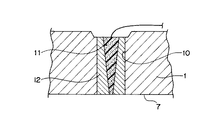
図2は、上記貫通穴10周辺の部分拡大図である。
FIG. 2 is a partially enlarged view around the through
図2に示すように、上記棒状の抵抗体11は、貫通穴10の略全長に亘って、貫通穴10の中心軸に略沿って延びており、抵抗体11の長さは、外輪1の軌道面7が形成されている部分の肉厚と略同じ寸法になっている。また、上記抵抗体11は、軌道面7に向けて先細りになっている(図2では、この先細り形状は、誇張されて描かれている)。また、上記抵抗体11の軌道面7側の端面は、円筒ころ3の周面と接触するようになっている。上記抵抗体11は、エポキシにモリブデンや鉛等の金属粒子を分散させた材料から構成されている。
As shown in FIG. 2, the rod-shaped
また、上記抵抗体11と貫通穴10の内周面との間には、抵抗体10の径方向の二つの端面を除いた外面部分を覆うように、上記絶縁体12が、隙間なく配置されている。上記絶縁体12は、抵抗体11と外輪1とが電気接続することを防止する役割を果たしている。上記絶縁体12は、ポリフェニレンサルファイド(PPS)から構成されている。
Further, the
上記構成において、以下の方法で、上記軌道面7の摩耗の度合いを測定する。
In the above configuration, the degree of wear of the
先ず、図1に示すように、上記抵抗体11の径方向の外方側の端面と、抵抗測定装置20の第1端子21とを、配線24を用いて接続すると共に、外輪1の軸方向の端面の一点と、抵抗測定装置20の第2端子22とを、配線25を用いて接続する。
First, as shown in FIG. 1, the radially outer end face of the
次に、抵抗測定装置20を駆動して、抵抗測定装置29の高電位側の第1端子21と低電位側の第2端子22との間に所定の電位差を発生させて、第1端子21、配線24、抵抗体11、円筒ころ3における抵抗体11との接触点から上記一点側の端面までの部分、外輪における上記一点側の鍔端面から上記一点までの部分、配線25、抵抗測定装置29の低電位側の第2端子22から成る回路に、図1に矢印で示す方向に電流を流して、抵抗測定装置29で、上記回路の全抵抗を測定する。
Next, the
続いて、上記回路の全抵抗の測定を、定期的に行って、上記全抵抗の変化を測定することにより、抵抗体11の抵抗値の変化を測定して、この抵抗値から一意に決定する抵抗体11の軌道面7側の端面位置を精密に割り出す。
Subsequently, the total resistance of the circuit is periodically measured, and the change in the total resistance is measured, whereby the change in the resistance value of the
ここで、上記回路において、時の経過と共に抵抗値が変動するのは、抵抗体11の抵抗値だけであることから、上記全抵抗値の変化量と、抵抗体の変化量とは、等しくなる。
Here, in the above circuit, since the resistance value fluctuates with time only in the resistance value of the
最後に、上記抵抗体11の軌道面7側の端面位置に基づいて、抵抗体11の軌道面7側の端面と外輪1の軸中心との距離を精密に算出して、この距離を軌道面7の内径として特定して、この軌道輪7の内径から軌道輪の摩耗の度合いを測定する。
Finally, based on the position of the end surface of the
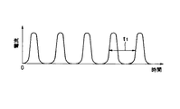
図3は、上記第1実施形態のセンサ付転がり軸受の運転中における、時間と、上記抵抗体11に流れる電流との関係を示す図である。
FIG. 3 is a diagram illustrating the relationship between time and the current flowing through the
図3に示すように、上記抵抗体11には、一定の時間間隔毎に、略一定の電流が流れることがわかる。これは、上記円筒ころ3は、軌道面7上を略一定の回転速度で、転動するため、抵抗体11と円筒ころ3との接触と、抵抗体11と円筒ころ3との非接触が、交互に発生するからであり、抵抗体11と円筒ころ3の接触時にしか、電流が流れないためである。
As shown in FIG. 3, it can be seen that a substantially constant current flows through the
尚、上記円筒ころ3の周方向の配置間隔がわかっているので、図3にt1で示す隣接する電流の立ち上がり点の時間差を算出することによって、保持器9の回転速度を算出することができる。
In addition, since the arrangement | positioning space | interval of the circumferential direction of the said
上記第1実施形態のセンサ付転がり軸受によれば、外輪1に、外輪1の軌道面7に開口した貫通穴10を形成し、貫通穴10に、略貫通穴10の中心軸の方向に延びる棒状の抵抗体11と、抵抗体11と貫通穴10の内周面との間に配置されて、抵抗体11と外輪1とが電気接続することを防止する絶縁体12とを配置しているので、抵抗体11の抵抗値を測定することによって、抵抗体11の摩耗の度合いを常時精密に測定でき、軌道面7の摩耗の度合いを常時精密に測定できる。
According to the sensor-equipped rolling bearing of the first embodiment, the
また、上記第1実施形態のセンサ付転がり軸受によれば、鍔部の摩耗ではなくて、転動輪に必ず存在する軌道面(第1実施形態では、軌道面7)の摩耗を測定するので、鍔部を有さない軌道輪においても、軌道輪(第1実施形態では、外輪1)の摩耗の度合いを常時精密に測定できる。
Further, according to the rolling bearing with sensor of the first embodiment, since the wear of the raceway surface (the
また、上記第1実施形態のセンサ付転がり軸受によれば、上記抵抗体11が、軌道面7に向けて先細りになっているので、抵抗体11の摩耗に起因する抵抗体11の抵抗値の変動を顕著にすることができる。したがって、軌道面7の摩耗の度合いを更に精度高く測定できる。
Moreover, according to the rolling bearing with a sensor of the said 1st Embodiment, since the said
また、上記第1実施形態のセンサ付転がり軸受によれば、上記抵抗体11が、先細りで、基部が太いので、この基部への電気配線の接続が容易になると共に、抵抗体11の取り扱いが容易になる。
Moreover, according to the rolling bearing with a sensor of the said 1st Embodiment, since the said
また、上記第1実施形態のセンサ付転がり軸受によれば、上記抵抗体11が、エポキシに金属粒子を分散した材料から構成されているので、抵抗体11の摩耗による抵抗値の変動を顕著にすることができると共に、抵抗体11の摩耗片が、外輪1と内輪2との間に浸入しても、潤滑性が低下することがなく、焼付を防止できる。
Moreover, according to the rolling bearing with a sensor of the said 1st Embodiment, since the said
また、上記第1実施形態のセンサ付転がり軸受によれば、上記絶縁体12が、ポリフェニレンサルファイドから構成されているので、抵抗体11と外輪1との間を確実に絶縁することができると共に、絶縁体12の摩耗片が、外輪1と内輪2との間に浸入しても、潤滑性が低下することがなく、焼付を防止できる。
Moreover, according to the rolling bearing with a sensor of the said 1st Embodiment, since the said
また、上記第1実施形態のセンサ付転がり軸受によれば、上記貫通穴10が形成されている外輪1が、固定輪であるので、抵抗体11が周方向に回転することがなくて、抵抗体11の抵抗値の測定を簡単に行うことができる。
Moreover, according to the rolling bearing with a sensor of the said 1st Embodiment, since the outer ring |
尚、上記第1実施形態のセンサ付転がり軸受では、上記抵抗体11を、エポキシにモリブデンや鉛等の金属粒子を分散した材料から構成したが、この発明のセンサ付転がり軸受では、抵抗体を、エポキシにモリブデンや鉛等の金属粒子を分散した材料以外の潤滑性を有する材料から構成しても良く、抵抗体を、潤滑性を有さない抵抗材料から構成しても良い。抵抗体を、潤滑性を有する材料から構成した場合、抵抗体11をエポキシにモリブデンや鉛等の金属粒子を分散した材料から構成した場合と同様に、抵抗体の摩耗片の潤滑剤への混入に起因する、潤滑剤の潤滑性の低下を小さくすることができる。
In the sensor-equipped rolling bearing of the first embodiment, the
また、上記第1実施形態のセンサ付転がり軸受では、上記絶縁体12を、ポリフェニレンサルファイドから構成したが、この発明のセンサ付転がり軸受では、絶縁体を、ポリフェニレンサルファイド以外の潤滑性を有する材料から構成しも良く、絶縁体を、潤滑性を有さない絶縁材料から構成しても良い。絶縁体を、潤滑性を有する材料から構成した場合、絶縁体12をポリフェニレンサルファイドから構成した場合と同様に、絶縁体の摩耗片の潤滑剤への混入に起因する、潤滑剤の潤滑性の低下を小さくすることができる。
Moreover, in the rolling bearing with a sensor of the said 1st Embodiment, although the said
また、上記第1実施形態のセンサ付転がり軸受では、抵抗体11を配置する貫通穴10を固定輪である外輪1に形成したが、この発明のセンサ付転がり軸受では、固定輪が内輪の場合、抵抗体を配置する貫通穴を内輪に形成しても良い。
In the sensor-equipped rolling bearing of the first embodiment, the through
また、上記第1実施形態のセンサ付転がり軸受では、抵抗体11を配置する貫通穴10を固定輪である外輪1に形成したが、この発明のセンサ付転がり軸受では、抵抗体を配置する貫通穴を転動輪(回転輪)に形成しても良く、スリップリング等を使用して外部と電気接続しても良い。また、電気回路が成立するのであれば、転動体に電気配線を接続しても良い。
Moreover, in the rolling bearing with a sensor of the said 1st Embodiment, although the through-
また、上記第1実施形態のセンサ付転がり軸受では、第1および第2の軌道面として円筒ころ用軌道面7,8を採用すると共に、転動体として円筒ころを採用したが、この発明では、第1および第2の軌道面として円錐ころ用軌道面を採用すると共に、転動体として円錐ころを採用しても良い、また、第1および第2の軌道面として軌道溝を採用すると共に、転動体として玉を採用しても良い。すなわち、この発明では、抵抗体を取付けられる軸受は、いかなる種類の軸受であっても良い。 In the rolling bearing with sensor of the first embodiment, the cylindrical roller raceway surfaces 7 and 8 are adopted as the first and second raceway surfaces, and the cylindrical roller is adopted as the rolling element. A tapered roller raceway may be employed as the first and second raceway surfaces, and a tapered roller may be employed as the rolling element, and a raceway groove may be employed as the first and second raceway surfaces. A ball may be adopted as a moving object. That is, in this invention, the bearing to which the resistor can be attached may be any type of bearing.
(第2実施形態)
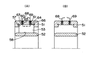
図4は、第2実施形態のセンサ付転がり軸受の軸方向の断面図である。
(Second Embodiment)
FIG. 4 is a sectional view in the axial direction of the rolling bearing with sensor of the second embodiment.
このセンサ付転がり軸受は、図4(A)に示すように、第1の軌道輪としての外輪51と、第2の軌道輪としての内輪52と、転動体としての円筒ころ53とを備える。
As shown in FIG. 4A, the sensor-equipped rolling bearing includes an
上記外輪51の内周側には、第1の軌道面としての円筒ころ用の軌道面57が形成され、内輪52の外周側には、上記軌道面57に対向する箇所に第2の軌道面としての円筒ころ用の軌道面58が形成されている。また、上記円筒ころ53は、外輪51の軌道面57と内輪52の軌道面58との間に、図示しない保持器によって保持された状態で、周方向に一定の間隔を隔てられて複数配置されている。
A
また、上記外輪51には、二つの略同一の貫通穴60,61が形成されている。この貫通穴60および61は、略径方向に延びて軌道面57に開口しており、軸方向に間隔を置いて形成されている。上記二つの貫通穴60,61の夫々には、第1実施形態の貫通穴10と全く同様な方法で、エポキシにモリブデンや鉛等の金属粒子を分散した材料製の抵抗体63,64およびポリフェニレンサルファイド製の絶縁体65,66が、配置されている。上記抵抗体63,64は、略同一であり、絶縁体65,66も、略同一である。
Further, two substantially identical through holes 60 and 61 are formed in the
図4(A)において、68および69は、配線である。この配線68および69は、図示しない抵抗測定装置の端子に接続されている。
In FIG. 4A, 68 and 69 are wirings. The
上記構成において、上記第1実施形態のセンサ付転がり軸受と同様な方法で、軌道面57の摩耗の度合いを測定する。
In the above configuration, the degree of wear of the
第2実施形態では、電流が流れる場合の、電気回路を、抵抗測定装置、配線68、抵抗体63、円筒ころ53、抵抗体64、配線69、抵抗測定装置で構成する。第2実施形態では、回路全体の抵抗値の変動は、抵抗体63または64の抵抗値の変動の略2倍になっている。
In the second embodiment, an electric circuit in the case where a current flows includes a resistance measuring device, a
尚、第2実施形態においても、図3に示すように、円筒ころ53の存在位置によって、上記電気回路に電流が流れたり流れなかったりする。図4(A)は、電気回路に電気が流れる円筒ころ53の配置であり、図4(B)は、電気回路に電気が流れない円筒ころ53(図4(B)には表れない)の配置である。
In the second embodiment as well, as shown in FIG. 3, current flows or does not flow in the electric circuit depending on the position of the
上記第2実施形態のセンサ付転がり軸受では、上記第1実施形態のセンサ付転がり軸受と共通の作用効果および変形例については説明を省略することにし、上記第1実施形態のセンサ付転がり軸受と異なる作用効果および変形例についてのみ説明を行うことにする。 In the sensor-equipped rolling bearing of the second embodiment, the description of the operation and effect common to the sensor-equipped rolling bearing of the first embodiment is omitted, and the sensor-equipped rolling bearing of the first embodiment is omitted. Only different effects and modifications will be described.
上記第2実施形態のセンサ付転がり軸受によれば、転動体が、円筒ころ53であり、貫通穴60,61が、軌道面57に開口するように、軸方向に間隔を置いて2つ形成されているので、2つの貫通穴60,61に配置されている各抵抗体63,64における径方向外方の端部間に電圧を印加することによって、抵抗測定装置、配線68、抵抗体63、円筒ころ53、抵抗体64、配線69、抵抗測定装置という回路を構成することができて、この回路の抵抗値を測定することができる。この場合、回路を構成するのに必要な円筒ころ53が一つであるので、抵抗体63,64の抵抗値をより精密に測定することができる。
According to the sensor-equipped rolling bearing of the second embodiment, the rolling element is the
尚、上記第2実施形態のセンサ付転がり軸受では、第1の軌道面として円筒ころ用の軌道面57を採用すると共に、第2の軌道面として円筒ころ用の軌道面58を採用し、転動体として円筒ころ53を採用したが、この発明のセンサ付転がり軸受では、第1の軌道面として円錐ころ用の軌道面を採用すると共に、第2の軌道面として円錐ころ用の軌道面を採用し、転動体として円錐ころを採用しても良い。
The sensor-equipped rolling bearing according to the second embodiment employs a
また、上記第2実施形態のセンサ付転がり軸受では、外輪51に、軌道面57に開口するように軸方向に間隔をおいて二つの貫通穴60,61を形成したが、この発明のセンサ付転がり軸受では、外輪に、軌道面に開口するように軸方向に間隔をおいて二つ以外の複数の貫通穴を形成しても良い。
Further, in the rolling bearing with sensor of the second embodiment, two through holes 60 and 61 are formed in the
(第3実施形態)
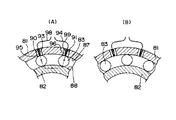
図5は、第3実施形態のセンサ付転がり軸受の径方向の断面図である。
(Third embodiment)
FIG. 5 is a radial cross-sectional view of the rolling bearing with sensor of the third embodiment.
このセンサ付転がり軸受は、図5(A)に示すように、第1の軌道輪としての外輪81と、第2の軌道輪としての内輪82と、転動体としての玉83とを備える。
As shown in FIG. 5A, the sensor-equipped rolling bearing includes an
上記外輪81の内周側には、第1の軌道面としての軌道溝87が形成され、内輪82の外周側には、上記軌道面87に対向する箇所に第2の軌道面としての軌道溝88が形成されている。また、上記玉83は、外輪81の軌道面87と内輪82の軌道面88との間に、図示しない保持器によって保持された状態で、周方向に一定の間隔を隔てられて複数配置されている。
A
また、上記外輪81には、二つの略同一の貫通穴90,91が形成されている。この貫通穴90および91は、略径方向に延びて軌道溝87に開口しており、周方向に間隔を置いて形成されている。
Further, two substantially identical through holes 90 and 91 are formed in the
上記二つの貫通穴90,91の夫々には、第1実施形態の貫通穴10と全く同様な方法で、エポキシにモリブデンや鉛等の金属粒子を分散した材料製の抵抗体93,94およびポリフェニレンサルファイド製の絶縁体95,96が、配置されている。上記抵抗体93,94は、略同一であり、絶縁体95,96も、略同一である。
In each of the two through holes 90 and 91,
図4(A)において、98および99は、配線である。この配線98および99は、図示しない抵抗測定装置の端子に接続されている。
In FIG. 4A,
上記構成において、上記第1実施形態のセンサ付転がり軸受と同様な方法で、軌道面87の摩耗の度合いを測定する。
In the above configuration, the degree of wear of the
第3実施形態では、電流が流れる場合の、電気回路を、抵抗測定装置、配線98、抵抗体93、玉83、内輪82、別の玉83、抵抗体94、配線99、抵抗測定装置で構成する。第3実施形態では、回路全体の抵抗値の変動は、抵抗体93または94の抵抗値の変動の2倍になっている。
In the third embodiment, when an electric current flows, an electric circuit is constituted by a resistance measuring device, a
尚、第3実施形態においても、図3に示すように、玉83の存在位置によって、上記電気回路に電流が流れたり流れなかったりする。図5(A)は、電気回路に電気が流れる玉83の配置であり、図5(B)は、電気回路に電気が流れない玉83の配置である。
In the third embodiment as well, as shown in FIG. 3, current flows or does not flow in the electric circuit depending on the position of the
上記第3実施形態のセンサ付転がり軸受では、上記第1実施形態のセンサ付転がり軸受と共通の作用効果および変形例については説明を省略することにし、上記第1実施形態のセンサ付転がり軸受と異なる作用効果および変形例についてのみ説明を行うことにする。 In the sensor-equipped rolling bearing of the third embodiment, the description of the operations and effects common to the sensor-equipped rolling bearing of the first embodiment is omitted, and the sensor-equipped rolling bearing of the first embodiment is omitted. Only different effects and modifications will be described.
上記第3実施形態のセンサ付転がり軸受によれば、貫通穴90,91が、軌道溝87に周方向に間隔を置いて2つ形成されているので、上記間隔を、隣接する玉83の周方向の間隔に設定した上で、2つの貫通穴90,91に配置されている各抵抗体93,94の径方向外方の端部間に電圧を印加することによって、抵抗測定装置、配線98、抵抗体93、玉83、内輪82、別の玉83、抵抗体94、配線99、抵抗測定装置という回路を構成することができて、電気回路の抵抗値を測定することができる。
According to the sensor-equipped rolling bearing of the third embodiment, two through holes 90 and 91 are formed in the
尚、上記第3実施形態のセンサ付転がり軸受では、第1の軌道面として軌道溝87を採用すると共に、第2の軌道面として軌道溝88を採用し、転動体として玉83を採用したが、この発明のセンサ付転がり軸受では、第1の軌道面として円筒ころ用の軌道面を採用すると共に、第2の軌道面として円筒ころ用の軌道面を採用し、転動体として円筒ころを採用しても良い、また、第1の軌道面として円錐ころ用の軌道面を採用すると共に、第2の軌道面として円錐ころ用の軌道面を採用し、転動体として円錐ころを採用しても良い。
The sensor-equipped rolling bearing of the third embodiment employs the
また、上記第3実施形態のセンサ付転がり軸受では、外輪81に、軌道面87に開口するように軸方向に間隔をおいて二つの貫通穴90,91を形成したが、この発明のセンサ付転がり軸受では、外輪に、軌道溝に開口するように周方向に間隔をおいて二つ以外の複数の貫通穴を形成しても良い。
Further, in the rolling bearing with sensor of the third embodiment, two through holes 90 and 91 are formed in the
1,51,81 外輪
2,52,82 内輪
3,53 円筒ころ
7,8,57,58 軌道面
10,60,61,90,91 貫通穴
11,63,64,93,94 抵抗体
12,65,66,95,96 絶縁体
83 玉
87,88 軌道溝
1,51,81
Claims (8)
第2の軌道面を有する第2の軌道輪と、
上記第1の軌道面と上記第2の軌道面との間に配置された転動体と
を備え、
上記第1の軌道輪には、上記第1の軌道面に開口した貫通穴が形成され、
上記貫通穴には、略上記貫通穴の中心軸の方向に延びる棒状の抵抗体と、上記抵抗体と上記第1の軌道輪とが電気接続されることを防止する絶縁体とが配置されていることを特徴とするセンサ付転がり軸受。 A first bearing ring having a first raceway surface;
A second race ring having a second raceway surface;
A rolling element disposed between the first raceway surface and the second raceway surface;
The first track ring is formed with a through hole that is open to the first track surface,
In the through hole, a rod-shaped resistor extending substantially in the direction of the central axis of the through hole and an insulator for preventing the resistor and the first raceway from being electrically connected are arranged. A rolling bearing with a sensor, characterized by comprising:
上記抵抗体は、上記第1の軌道面に向けて先細りになっていることを特徴とするセンサ付転がり軸受。 In the rolling bearing with a sensor according to claim 1,
A rolling bearing with a sensor, wherein the resistor is tapered toward the first raceway surface.
上記抵抗体は、潤滑性を有していることを特徴とするセンサ付転がり軸受。 In the sensor rolling bearing according to claim 1 or 2,
A rolling bearing with a sensor, wherein the resistor has lubricity.
上記絶縁体は、潤滑性を有していることを特徴とするセンサ付転がり軸受。 In the rolling bearing with a sensor according to any one of claims 1 to 3,
A rolling bearing with a sensor, wherein the insulator has lubricity.
上記抵抗体は、エポキシに金属粒子を分散した材料から構成され、上記絶縁体は、ポリフェニレンサルファイドから構成されていることを特徴とするセンサ付転がり軸受。 In the rolling bearing with a sensor according to claim 1 or 2,
A rolling bearing with a sensor, wherein the resistor is made of a material in which metal particles are dispersed in epoxy, and the insulator is made of polyphenylene sulfide.
上記第1の軌道輪は、固定輪であることを特徴とするセンサ付転がり軸受。 In the rolling bearing with a sensor according to any one of claims 1 to 5,
The rolling bearing with sensor, wherein the first race ring is a fixed ring.
上記転動体は、円筒ころまたは円錐ころであり、上記貫通穴は、上記第1の軌道輪に軸方向に間隔を置いて2つ形成されていることを特徴とするセンサ付転がり軸受。 In the rolling bearing with a sensor according to any one of claims 1 to 6,
2. The sensor-equipped rolling bearing according to claim 1, wherein the rolling element is a cylindrical roller or a tapered roller, and two through holes are formed in the first raceway with an interval in the axial direction.
上記貫通穴は、上記第1の軌道輪に周方向に間隔を置いて2つ形成されていることを特徴とするセンサ付転がり軸受。
In the rolling bearing with a sensor according to any one of claims 1 to 6,
2. The sensor-equipped rolling bearing according to claim 1, wherein two through holes are formed in the first track ring at intervals in the circumferential direction.
Priority Applications (1)
| Application Number | Priority Date | Filing Date | Title |
|---|---|---|---|
| JP2004104666A JP2005291287A (en) | 2004-03-31 | 2004-03-31 | Rolling bearing with sensor |
Applications Claiming Priority (1)
| Application Number | Priority Date | Filing Date | Title |
|---|---|---|---|
| JP2004104666A JP2005291287A (en) | 2004-03-31 | 2004-03-31 | Rolling bearing with sensor |
Publications (2)
| Publication Number | Publication Date |
|---|---|
| JP2005291287A true JP2005291287A (en) | 2005-10-20 |
| JP2005291287A5 JP2005291287A5 (en) | 2007-04-19 |
Family
ID=35324458
Family Applications (1)
| Application Number | Title | Priority Date | Filing Date |
|---|---|---|---|
| JP2004104666A Pending JP2005291287A (en) | 2004-03-31 | 2004-03-31 | Rolling bearing with sensor |
Country Status (1)
| Country | Link |
|---|---|
| JP (1) | JP2005291287A (en) |
Cited By (2)
| Publication number | Priority date | Publication date | Assignee | Title |
|---|---|---|---|---|
| CN105122025A (en) * | 2012-12-14 | 2015-12-02 | Skf公司 | Fibre sensor assembly |
| JPWO2023166567A1 (en) * | 2022-03-01 | 2023-09-07 |
-
2004
- 2004-03-31 JP JP2004104666A patent/JP2005291287A/en active Pending
Cited By (4)
| Publication number | Priority date | Publication date | Assignee | Title |
|---|---|---|---|---|
| CN105122025A (en) * | 2012-12-14 | 2015-12-02 | Skf公司 | Fibre sensor assembly |
| JPWO2023166567A1 (en) * | 2022-03-01 | 2023-09-07 | ||
| WO2023166567A1 (en) * | 2022-03-01 | 2023-09-07 | 三菱電機株式会社 | Rolling bearing abnormality detection device, rolling bearing abnormality diagnosis device, train abnormality monitoring system and rolling bearing abnormality diagnosis method |
| JP7471523B2 (en) | 2022-03-01 | 2024-04-19 | 三菱電機株式会社 | Rolling bearing abnormality detection device, rolling bearing abnormality diagnosis device, and train abnormality monitoring system |
Similar Documents
| Publication | Publication Date | Title |
|---|---|---|
| US9464672B2 (en) | Rolling bearing with integrated electrical shunt | |
| KR101428829B1 (en) | Sen style bearing unit | |
| US9581203B2 (en) | Shunt bearing with insulating coating | |
| ES2219827T3 (en) | WEAR MEASUREMENT DEVICE FOR LARGE BEARINGS. | |
| EP2955395B1 (en) | Electrically conductive bearing system and manufacturing method | |
| JP6536170B2 (en) | Rolling bearing provided with vibration detection device and state detection device | |
| JPH0961268A (en) | Bearing load measuring device | |
| CN105518322B (en) | Rolling bearing device | |
| US20120068575A1 (en) | Rotatable antifriction bearing | |
| US7071834B2 (en) | Device for monitoring the operating conditions of rolling bearing | |
| US9933018B2 (en) | Bearing with condition monitoring sensor | |
| JP2005291287A (en) | Rolling bearing with sensor | |
| US20160281788A1 (en) | Capacitance measurement in a bearing housing | |
| CN113825920A (en) | Device for monitoring the degradation of a rolling bearing | |
| CN106015351A (en) | Capacitance measurement in a bearing housing | |
| JP2003206925A (en) | Bearing preload measuring method, preload measuring device, and spindle device. | |
| JP2016217726A (en) | Lubricating state diagnostic device for rolling bearing and lubricating state diagnostic method for rolling bearing | |
| CN112815000A (en) | Bearing assembly and device with same | |
| JP6047963B2 (en) | Preload measurement method for rolling bearings | |
| US11226005B2 (en) | Bearing arrangements, and module carrier for them | |
| JP2007298527A (en) | Spindle support device | |
| JP2008196956A (en) | Bearing with sensor and manufacturing method thereof | |
| JP2008026216A (en) | Inner ring temperature measuring instrument for rolling bearing | |
| JPH10184705A (en) | Grease feeding device for bearing | |
| JPH11148803A (en) | Wear detection bearing |
Legal Events
| Date | Code | Title | Description |
|---|---|---|---|
| A521 | Written amendment |
Free format text: JAPANESE INTERMEDIATE CODE: A523 Effective date: 20070306 |
|
| A621 | Written request for application examination |
Free format text: JAPANESE INTERMEDIATE CODE: A621 Effective date: 20070306 |
|
| A977 | Report on retrieval |
Free format text: JAPANESE INTERMEDIATE CODE: A971007 Effective date: 20090402 |
|
| A131 | Notification of reasons for refusal |
Free format text: JAPANESE INTERMEDIATE CODE: A131 Effective date: 20090924 |
|
| RD04 | Notification of resignation of power of attorney |
Free format text: JAPANESE INTERMEDIATE CODE: A7424 Effective date: 20091225 |
|
| A02 | Decision of refusal |
Free format text: JAPANESE INTERMEDIATE CODE: A02 Effective date: 20100209 |