JP2005291277A - Vehicle disc brake - Google Patents
Vehicle disc brake Download PDFInfo
- Publication number
- JP2005291277A JP2005291277A JP2004104324A JP2004104324A JP2005291277A JP 2005291277 A JP2005291277 A JP 2005291277A JP 2004104324 A JP2004104324 A JP 2004104324A JP 2004104324 A JP2004104324 A JP 2004104324A JP 2005291277 A JP2005291277 A JP 2005291277A
- Authority
- JP
- Japan
- Prior art keywords
- stopper pin
- caliper body
- disc brake
- press
- mounting hole
- Prior art date
- Legal status (The legal status is an assumption and is not a legal conclusion. Google has not performed a legal analysis and makes no representation as to the accuracy of the status listed.)
- Pending
Links
- 238000005260 corrosion Methods 0.000 claims abstract description 13
- 230000007797 corrosion Effects 0.000 claims abstract description 13
- 229910052782 aluminium Inorganic materials 0.000 claims abstract description 11
- XAGFODPZIPBFFR-UHFFFAOYSA-N aluminium Chemical compound [Al] XAGFODPZIPBFFR-UHFFFAOYSA-N 0.000 claims abstract description 11
- 229910000838 Al alloy Inorganic materials 0.000 claims abstract description 9
- 230000002093 peripheral effect Effects 0.000 claims abstract description 7
- 238000004381 surface treatment Methods 0.000 claims description 5
- XEEYBQQBJWHFJM-UHFFFAOYSA-N Iron Chemical compound [Fe] XEEYBQQBJWHFJM-UHFFFAOYSA-N 0.000 description 8
- 229910052742 iron Inorganic materials 0.000 description 4
- 229910052751 metal Inorganic materials 0.000 description 4
- 239000002184 metal Substances 0.000 description 4
- 239000000463 material Substances 0.000 description 3
- 238000000034 method Methods 0.000 description 3
- XLYOFNOQVPJJNP-UHFFFAOYSA-N water Substances O XLYOFNOQVPJJNP-UHFFFAOYSA-N 0.000 description 3
- 150000002739 metals Chemical class 0.000 description 2
- 238000005536 corrosion prevention Methods 0.000 description 1
- 230000000694 effects Effects 0.000 description 1
Images
Landscapes
- Braking Arrangements (AREA)
Abstract
【課題】 アルミニウムあるいはアルミニウム合金からなるキャリパボディを備えた車両用ディスクブレーキにおいて、ストッパピンのキャリパボディへの取り付け部で電食作用が生じることを防止する。
【解決手段】 アルミニウムまたはアルミニウム合金からなるキャリパボディ10に機械式のパーキング機構14、17を設けた車両用ディスクブレーキであって、前記キャリパボディ10に、前記パーキング機構のリターンスプリング17を係止するストッパピン18を圧入、固定したものにおいて、前記ストッパピン18を圧入、固定する、前記キャリパボディ10に設けられた取り付け穴の開口部の周縁部に面取り部を設け、前記ストッパピン18の軸部の中途に、前記取り付け穴にストッパピン18を圧入した際に前記面取り部を塞ぐフランジ部19を設けたことを特徴とする。
【選択図】 図1PROBLEM TO BE SOLVED: To prevent an electrolytic corrosion action at a mounting portion of a stopper pin to a caliper body in a vehicle disc brake having a caliper body made of aluminum or an aluminum alloy.
A disk brake for a vehicle in which a mechanical parking mechanism (14, 17) is provided on a caliper body (10) made of aluminum or an aluminum alloy, and a return spring (17) of the parking mechanism is locked to the caliper body (10). In the case where the stopper pin 18 is press-fitted and fixed, a chamfered portion is provided at the peripheral portion of the opening of the mounting hole provided in the caliper body 10 for press-fitting and fixing the stopper pin 18, and the shaft portion of the stopper pin 18 In the middle, a flange portion 19 is provided to close the chamfered portion when the stopper pin 18 is press-fitted into the mounting hole.
[Selection] Figure 1
Description
本発明は車両用ディスクブレーキに関し、より詳細にはアルミニウムあるいはアルミニウム合金からなるキャリパボディを備えた車両用ディスクブレーキに関する。 The present invention relates to a vehicle disc brake, and more particularly to a vehicle disc brake having a caliper body made of aluminum or an aluminum alloy.
車両用ディスクブレーキでは、手動ブレーキ操作によってブレーキワイヤの牽引により回動作動されるパーキングレバーを備えたものが知られている(たとえば、特許文献1参照)。 BACKGROUND ART A vehicle disc brake is known that includes a parking lever that is rotated by pulling a brake wire by a manual brake operation (see, for example, Patent Document 1).
また一方、車両用ディスクブレーキでは軽量化を図る目的からキャリパボディをアルミニウムあるいはアルミニウム合金によって製作した製品が提供されるようになってきた。このような製品では、キャリパボディに取り付ける部材や部材の締め付け固定に使用するボルト等の部品が、アルミニウムよりも電位の高い鉄等の金属からなる場合に、これらの異種金属が接触する部分で電食作用が生じ、アルミニウムが腐蝕する場合がある。
このような異種金属間の電食作用を防止する方法として、異種金属が接触する部位に絶縁ワッシャのような電食防止部材を介在させる方法や、アルミニウムからなる部材に接触する鉄等からなる部材の表面に、あらかじめ電食防止用として電食防止表面処理を施す方法がある(たとえば、特許文献2参照)。
As a method for preventing the galvanic action between different kinds of metals, a method of interposing an galvanic corrosion prevention member such as an insulating washer at a portion where the different kinds of metal come into contact, or a member made of iron or the like that comes into contact with a member made of aluminum. There is a method in which a surface treatment is carried out in advance to prevent galvanic corrosion (for example, see Patent Document 2).
ところで、パーキングレバーを備えた車両用ディスクブレーキでは、パーキングレバーのストッパピンをキャリパボディに取り付け穴に圧入固定するが、ストッパピンは鉄系材料からなるから、キャリパボディがアルミニウムあるいはアルミニウム合金製であると、キャリパボディとストッパピンとの間で電食作用が生じる可能性がある。 By the way, in a vehicle disc brake equipped with a parking lever, the stopper pin of the parking lever is press-fitted and fixed to the mounting hole in the caliper body. Since the stopper pin is made of an iron-based material, the caliper body is made of aluminum or an aluminum alloy. Then, there is a possibility that an electrolytic corrosion action occurs between the caliper body and the stopper pin.
本発明は、アルミニウムあるいはアルミニウム合金からなるキャリパボディを備えた車両用ディスクブレーキにおいて、特にストッパピンとキャリパボディとの取り付け部で電食作用が生じることを防止する車両用ディスクブレーキを提供することを目的とする。 An object of the present invention is to provide a vehicle disc brake having a caliper body made of aluminum or an aluminum alloy, and in particular, a vehicle disc brake that prevents an electrolytic corrosion action from occurring at an attachment portion between a stopper pin and a caliper body. And
本発明は上記目的を達成するため次の構成を備える。
すなわち、アルミニウムまたはアルミニウム合金からなるキャリパボディに機械式のパーキング機構を設けた車両用ディスクブレーキであって、前記キャリパボディに、前記パーキング機構のリターンスプリングを係止するストッパピンを圧入固定したものにおいて、前記ストッパピンを圧入固定する、前記キャリパボディに設けられた取り付け穴の開口部の周縁部に面取り部を設け、前記ストッパピンの軸部の中途に、前記取り付け穴にストッパピンを圧入した際に前記面取り部を塞ぐフランジ部を設けたことを特徴とする。
また、前記フランジ部の、前記面取り部に対向する面にテーパ部を設け、該テーパ部のテーパ面に前記面取り部の外周端縁を環状に当接させたことにより、取り付け穴および面取り部がストッパピンにより、外部からさらに確実にシールされた状態で遮蔽される。
また、前記ストッパピンの表面に、電食防止表面処理が施されていることにより、ストッパピンとキャリパボディとの電食作用をさらに確実に防止することができる。
In order to achieve the above object, the present invention comprises the following arrangement.
That is, in a vehicle disc brake provided with a mechanical parking mechanism on a caliper body made of aluminum or aluminum alloy, a stopper pin for locking a return spring of the parking mechanism is press-fitted and fixed to the caliper body. When the stopper pin is press-fitted and fixed, a chamfered portion is provided in the peripheral portion of the opening portion of the mounting hole provided in the caliper body, and the stopper pin is press-fitted into the mounting hole in the middle of the shaft portion of the stopper pin. And a flange portion for closing the chamfered portion.
Further, a taper portion is provided on a surface of the flange portion facing the chamfered portion, and an outer peripheral edge of the chamfered portion is annularly contacted with the tapered surface of the taper portion so that the mounting hole and the chamfered portion are formed. By the stopper pin, it is shielded in a state of being more reliably sealed from the outside.
In addition, since the surface of the stopper pin is subjected to an electrolytic corrosion preventing surface treatment, the electrolytic corrosion action between the stopper pin and the caliper body can be more reliably prevented.
本発明に係る車両用ディスクブレーキは、ストッパピンにフランジ部を設け、ストッパピンを取り付け穴に圧入固定した際に、フランジ部によって取り付け穴の面取り部が外部に露出しないよう塞ぐことを可能にしたことにより、ストッパピンの取り付け部に水等が溜まったりすることを防止して、キャリパボディとストッパピンとの取り付け部で電食作用が生じやすくなることを防止することが可能になる。 The disc brake for a vehicle according to the present invention is provided with a flange portion on the stopper pin, and when the stopper pin is press-fitted and fixed to the mounting hole, the flange portion can block the chamfered portion of the mounting hole from being exposed to the outside. As a result, it is possible to prevent water or the like from accumulating at the stopper pin mounting portion, and to prevent the electrolytic corrosion action from easily occurring at the caliper body and the stopper pin mounting portion.
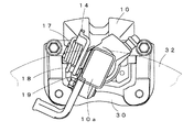
図1は、本発明に係る機械式のパーキング機構付き車両用ディスクブレーキの一実施形態を示す。図1は、ストッパピン18、パーキングレバー14、リターンスプリング17等の構成をディスクロータ32の軸線方向から見た状態を示す。なお、キャリパボディ10はアルミニウム合金製であり、キャリパボディブラケット30を介して車両に支持される。
本発明において特徴的な構成を備えるストッパピン18は作用部10aに設けられた取り付け穴に圧入され、作用部10aに突設されている。
FIG. 1 shows an embodiment of a vehicle disc brake with a mechanical parking mechanism according to the present invention. FIG. 1 shows a state in which the configuration of the
The
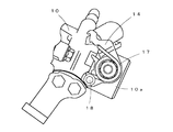
図2に、ストッパピン18とパーキングレバー14等の平面配置を示す。パーキングレバー14は作用部10aに回動可能に取り付けられ、パーキングレバー14とストッパピン18との間に係止されたリターンスプリング17のトーション力により、常時は、パーキングレバー14の基端部がストッパピン22の外面に当接して非作動方向へ付勢されている。ストッパピン18はパーキングレバー14の非作動方向への回動を規制するためのものである。
FIG. 2 shows a planar arrangement of the
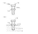
図3に、本実施形態の車両用ディスクブレーキにおいて使用しているストッパピン18の構成を示す。図3(a)は、ストッパピン18の全体構成を示す正面図、図3(b)はストッパピン18をキャリパボディ10に設けた取り付け穴11に圧入してキャリパボディ10に立設した状態を示す説明図である。
FIG. 3 shows the configuration of the
ストッパピン18は、軸部18aと、ヘッド18bと、軸部18aの中途部に設けた環状のフランジ部19とからなる。フランジ部19は図3(b)に示すように、取り付け穴11にストッパピン18を圧入した際に、取り付け穴11の開口縁に設けられている面取り部11aが外部に露出しないように面取り部11aよりも大径に形成される。また、ストッパピン18を取り付け穴11に圧入した状態で、フランジ部19の取り付け穴11に対向する面がキャリパボディ10の外面に当接し、面取り部11aを含む取り付け穴11が外部から遮蔽されるように軸部18aでの軸線方向の位置を決める。
図1では、ストッパピン18のフランジ部19が作用部10aの表面に当接してストッパピン18が取り付けられていることを示す。
The
FIG. 1 shows that the
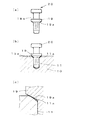
図4は、本発明に係る車両用ディスクブレーキで使用するストッパピン20の他の構成例を示す。図4(a)がストッパピン20の全体構成を示す正面図、図4(b)がストッパピン20を取り付け穴11に圧入した状態を示す説明図、図4(c)がストッパピン20と取り付け穴11との当接状態を拡大して示す説明図である。
図4(a)に示すように、ストッパピン20も図3に示すストッパピン18と同様に、軸部18aの中途部に、ストッパピン20を取り付け穴11に圧入した際に、取り付け穴11の面取り部11aが外部に露出しないよう遮蔽する環状のフランジ部19を設けた構成を備えている。本実施形態のストッパピン20において特徴的な構成は、フランジ部19の取り付け穴11に対向する面をテーパ部19aとした点にある。
FIG. 4 shows another configuration example of the
As shown in FIG. 4A, the
図4(c)は、取り付け穴11にストッパピン20を圧入した際に、ストッパピン20のテーパ部19aが取り付け穴11の開口縁に形成された面取り部11aの外周端縁に当接している状態を示す。ストッパピン20のフランジ部19にテーパ部19aを形成した場合には、テーパ部19aが面取り部11aの外周端縁に当接し、テーパ部19aのテーパ面と面取り部11aの外周端縁とが強固に当接することによって、ストッパピン20を取り付け穴11に圧入した際に、取り付け穴11に水等が侵入しないように確実にシールすることが可能になる。
4C, when the
上述したストッパピン18、20は、鉄系材料を用いて、軸部18aとヘッド18bとフランジ部19とが一体に形成されたものである。これらストッパピン18、20の材質はとくに限定されるものではない。また、キャリパボディ10との電食作用を防止するため、ストッパピン18、20に電食防止表面処理を施してもよい。電食防止表面処理としては、たとえばダクロダイズド処理(商品名)が使用できる。
The
上記実施形態のストッパピン18、20は、上述したように、ストッパピン18、20を取り付け穴11に圧入固定した際に、フランジ部19によって面取り部11aを含めて取り付け穴11を外部から遮蔽した状態で取り付けられるから、ストッパピンの基部に水等が付着することを防止し、ストッパピンとキャリパボディ10との間で電食作用が生じやすくなることを抑えることが可能となる。
As described above, the
本実施形態の車両用ディスクブレーキは、上述したフランジ部19を備えたストッパピン18、フランジ部19およびテーパ部19aを備えたストッパピン20を使用することにより、ストッパピン18、20を突設した取り付け穴11の近傍でキャリパボディ10との間で電食作用が生じることを抑制することが可能となる。なお、上記ストッパピン18、20は軸部18aと一体にフランジ部19、テーパ部19aを形成してなるから、車両用ディスクブレーキを組み立てる際には、従来のストッパピンとまったく同様の操作によって取り付け穴11に圧入固定することができるという利点もある。
The vehicle disc brake of the present embodiment uses the
10 キャリパボディ
10a 作用部
11 取り付け穴
11a 面取り部
14 パーキングレバー
17 リターンスプリング
18、20 ストッパピン
18a 軸部
18b ヘッド
19 フランジ部
19a テーパ部
30 キャリパブラケット
32 ディスクロータ
DESCRIPTION OF
Claims (3)
前記ストッパピンを圧入固定する、前記キャリパボディに設けられた取り付け穴の開口部の周縁部に面取り部を設け、
前記ストッパピンの軸部の中途に、前記取り付け穴にストッパピンを圧入した際に前記面取り部を塞ぐフランジ部を設けたことを特徴とする車両用ディスクブレーキ。 A disc brake for a vehicle in which a mechanical parking mechanism is provided on a caliper body made of aluminum or an aluminum alloy, wherein a stopper pin for locking a return spring of the parking mechanism is press-fitted and fixed to the caliper body.
A chamfered portion is provided at the periphery of the opening of the mounting hole provided in the caliper body for press-fitting and fixing the stopper pin,
A vehicular disc brake comprising a flange portion for closing the chamfered portion when the stopper pin is press-fitted into the mounting hole in the middle of the shaft portion of the stopper pin.
該テーパ部のテーパ面に前記面取り部の外周端縁部を環状に当接させたことを特徴とする請求項1記載の車両用ディスクブレーキ。 A taper portion is provided on a surface of the flange portion that faces the chamfered portion,
2. The vehicle disc brake according to claim 1, wherein an outer peripheral edge of the chamfered portion is annularly contacted with a tapered surface of the tapered portion.
Priority Applications (1)
| Application Number | Priority Date | Filing Date | Title |
|---|---|---|---|
| JP2004104324A JP2005291277A (en) | 2004-03-31 | 2004-03-31 | Vehicle disc brake |
Applications Claiming Priority (1)
| Application Number | Priority Date | Filing Date | Title |
|---|---|---|---|
| JP2004104324A JP2005291277A (en) | 2004-03-31 | 2004-03-31 | Vehicle disc brake |
Publications (1)
| Publication Number | Publication Date |
|---|---|
| JP2005291277A true JP2005291277A (en) | 2005-10-20 |
Family
ID=35324448
Family Applications (1)
| Application Number | Title | Priority Date | Filing Date |
|---|---|---|---|
| JP2004104324A Pending JP2005291277A (en) | 2004-03-31 | 2004-03-31 | Vehicle disc brake |
Country Status (1)
| Country | Link |
|---|---|
| JP (1) | JP2005291277A (en) |
Cited By (1)
| Publication number | Priority date | Publication date | Assignee | Title |
|---|---|---|---|---|
| DE102011006196A1 (en) | 2010-05-31 | 2011-12-01 | Hitachi Automotive Systems, Ltd. | Disk brake |
-
2004
- 2004-03-31 JP JP2004104324A patent/JP2005291277A/en active Pending
Cited By (2)
| Publication number | Priority date | Publication date | Assignee | Title |
|---|---|---|---|---|
| DE102011006196A1 (en) | 2010-05-31 | 2011-12-01 | Hitachi Automotive Systems, Ltd. | Disk brake |
| US8678146B2 (en) | 2010-05-31 | 2014-03-25 | Hitachi Automotive Systems, Ltd. | Disk brake |
Similar Documents
| Publication | Publication Date | Title |
|---|---|---|
| CA2864083C (en) | Control arm assembly with ball joint for automotive suspension | |
| JP2010106916A (en) | Disk rotor | |
| US20070278850A1 (en) | Wheel and wheel disk | |
| US5785332A (en) | Motor vehicle steering knuckle assembly | |
| JP2005291277A (en) | Vehicle disc brake | |
| JP2010106917A (en) | Disc rotor | |
| EP3779226B1 (en) | A guide assembly for a disc brake | |
| JP5200418B2 (en) | Bearing unit | |
| JP4856132B2 (en) | Fastening structure | |
| JP3683101B2 (en) | Wheel mounting structure | |
| US12163551B2 (en) | Support structure | |
| JP2005291278A (en) | Electric corrosion prevention bolt and brake device for vehicle | |
| JP2738228B2 (en) | Disc brake | |
| JP4519003B2 (en) | Wheel bearing device | |
| JP2005315283A (en) | Vehicle disc brake | |
| KR20070059709A (en) | Mounting structure of the car seat back frame | |
| JP4519004B2 (en) | Wheel bearing device | |
| JP4174290B2 (en) | Hose intermediate holding bracket | |
| JPH10246256A (en) | Waterproof structure of vehicle drum brake | |
| CN100545479C (en) | On axis hole, be provided with the combination shoe piece of lining | |
| JP2001248761A (en) | Intermediate holding metal fitting and hose assembly | |
| JPH11124013A (en) | Automotive wiper | |
| JP2005082140A (en) | Forged suspension member and suspension arm | |
| JP2006118548A (en) | Wheel bearing device | |
| JP2010133435A (en) | Rustproof structure of brake device |