JP2005291258A - Method for inserting corrugated pipe into existing piping - Google Patents
Method for inserting corrugated pipe into existing piping Download PDFInfo
- Publication number
- JP2005291258A JP2005291258A JP2004104025A JP2004104025A JP2005291258A JP 2005291258 A JP2005291258 A JP 2005291258A JP 2004104025 A JP2004104025 A JP 2004104025A JP 2004104025 A JP2004104025 A JP 2004104025A JP 2005291258 A JP2005291258 A JP 2005291258A
- Authority
- JP
- Japan
- Prior art keywords
- corrugated
- pipe
- tube
- corrugated pipe
- existing
- Prior art date
- Legal status (The legal status is an assumption and is not a legal conclusion. Google has not performed a legal analysis and makes no representation as to the accuracy of the status listed.)
- Pending
Links
Images


Landscapes
- Lining Or Joining Of Plastics Or The Like (AREA)
Abstract
Description
本発明は、老朽化した既設配管の内部に新たな管路としてコルゲート管を挿入して更新する工法に関する。 The present invention relates to a method for renewing a corrugated pipe by inserting a corrugated pipe as a new pipe inside an aged existing pipe.
ガスや水道の既設配管が老朽化した場合、地面等を掘削して配管を新しく交換する代わりに、既設配管内に可撓性のあるコルゲート管を挿入し、このコルゲート管を新しい配管として使用する方法が行われている。 When the existing pipes for gas and water are aged, instead of excavating the ground and replacing the pipes, insert a flexible corrugated pipe into the existing pipe and use this corrugated pipe as a new pipe. The way is done.
この既設配管へのコルゲート管の挿入工法としては、既設配管の一方の開口端から他方の開口端まで挿通された牽引用の線状材に、樹脂製のコルゲート管の先端を既設配管の一方の開口端側で固定したのち、既設配管の他方の開口端側から前記線状材を牽引する牽引動作と、既設配管の一方の開口端側からコルゲート管を既設配管内に押し込む押し込み動作とを行い、既設配管内にコルゲート管を挿入する工法(たとえば、特許文献1参照)が既に提案されている。
また、この工法では、コルゲート管の牽引は、まず、コルゲート管を挿入しようとする既設配管の一端から他端に向かって牽引用ワイヤロープを挿入し、コルゲート管の内壁面に形成された凹溝に牽引治具の凸部を係止させた状態で牽引治具に牽引用ワイヤロープの一端を固定し、他端から牽引するようにしている。
As a method of inserting the corrugated pipe into the existing pipe, the tip of the resin corrugated pipe is inserted into one of the existing pipes on the pulling linear member inserted from one open end of the existing pipe to the other open end. After fixing at the open end side, perform the pulling operation to pull the linear material from the other open end side of the existing pipe, and push-in operation to push the corrugated pipe into the existing pipe from the one open end side of the existing pipe A method of inserting a corrugated pipe into an existing pipe has already been proposed (for example, see Patent Document 1).
In this construction method, the corrugated pipe is pulled first by inserting a pulling wire rope from one end of the existing pipe to which the corrugated pipe is to be inserted toward the other end, and a concave groove formed on the inner wall surface of the corrugated pipe. One end of the pulling wire rope is fixed to the pulling jig in a state where the convex portion of the pulling jig is locked to the pulling jig, and is pulled from the other end.
ところで、本発明者らの検討したところによれば、上記の方法でも一定の曲がりを挿通することは可能であるが、コルゲート管の口径が大きく肉厚が厚い場合や、内部を流れる流体の圧力損失増加を低く抑えるために、コルゲート形状の凹凸が小さい場合などには、コルゲート管の屈曲性が一般的に悪く、多くの曲がりを通過させることが困難であった。
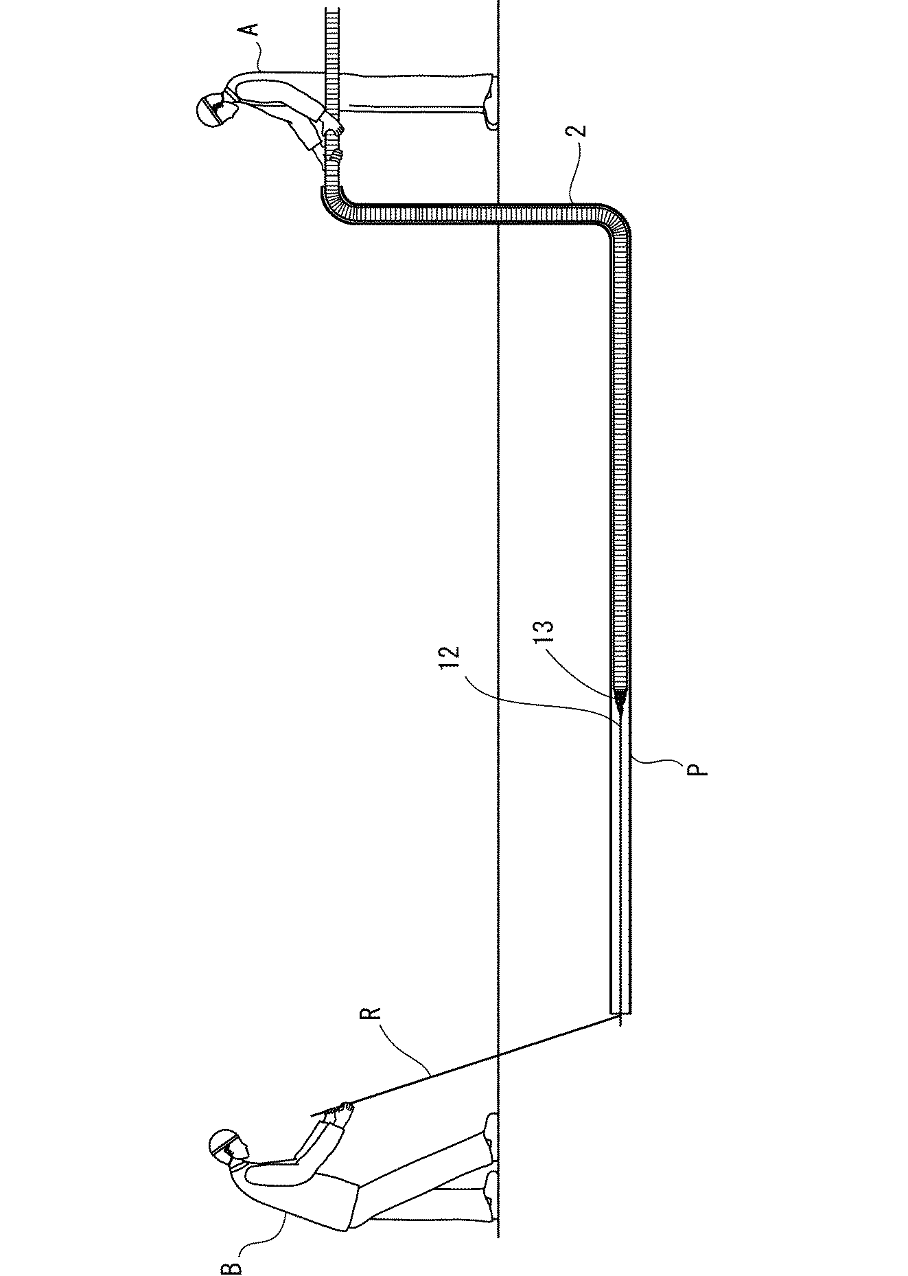
すなわち、屈曲性が悪いと、図8に示す既設配管Rの曲がり部の丸印で示す部分で、コルゲート管2と既設配管Rとの接触抵抗が大きくなる。
By the way, according to the study by the present inventors, it is possible to insert a certain bend even with the above method, but when the corrugated pipe has a large diameter and is thick, or the pressure of the fluid flowing inside In order to suppress the increase in loss to a low level, when the corrugated shape of the corrugated shape is small, the corrugated tube is generally poorly bent, making it difficult to pass many bends.
That is, if the flexibility is poor, the contact resistance between the
また、このような状態でコルゲート管を無理に通過させようとすると、コルゲート管が破損したり、傷付いたりする場合があった。 In addition, if the corrugated tube is forced to pass through in such a state, the corrugated tube may be damaged or damaged.
本発明は、上記事情に鑑みて、コルゲート管の口径が大きく肉厚が厚い場合や、内部を流れる流体の圧力損失増加を低く抑えるために、コルゲート形状の凹凸が小さい場合などにおいても、多くの曲がりをスムースに通過させることができる既設配管へのコルゲート管の挿入工法を提供することを目的としている。 In view of the above circumstances, the present invention has many corrugated pipes having a large diameter and a large thickness, and in order to suppress an increase in pressure loss of a fluid flowing through the corrugated pipe, An object of the present invention is to provide a method for inserting a corrugated pipe into an existing pipe that can smoothly pass a bend.
そこで、本発明の発明者らは、上記目的を達成するために、鋭意検討を重ねた結果、コルゲート管を既設配管に挿入するときに、コルゲート管を熱変形せず可撓性が増す温度まで加温しておけば、上記問題が解決できることが分かり、本発明を完成するに到った。 Therefore, the inventors of the present invention have made extensive studies in order to achieve the above object, and as a result, when the corrugated pipe is inserted into the existing pipe, the corrugated pipe is not thermally deformed and the flexibility is increased. It was found that the above problems could be solved by heating, and the present invention was completed.
すなわち、本発明の請求項1に記載の既設配管へのコルゲート管の挿入工法(以下、「請求項1の挿入工法」と記す)は、既設配管の一方の開口端から他方の開口端まで挿通された牽引用線状材に、熱可塑性樹脂製のコルゲート管の先端を既設配管の一方の開口端側で固定したのち、既設配管の他方の開口端側から前記牽引用線状材を牽引する牽引動作と、既設配管の一方の開口端側からコルゲート管を既設配管内に押し込む押し込み動作とを行い、既設配管内にコルゲート管を挿入する既設配管へのコルゲート管の挿入工法において、コルゲート管を既設配管への挿入前および挿入途中の少なくともいずれかのタイミングでコルゲート管が熱変形せず可撓性が増す温度まで加温することを特徴としている。 That is, the corrugated pipe insertion method (hereinafter referred to as “the insertion method of claim 1”) into the existing pipe according to claim 1 of the present invention is inserted from one open end of the existing pipe to the other open end. After fixing the tip of the corrugated pipe made of thermoplastic resin to the one open end side of the existing pipe, the towed linear member is pulled from the other open end side of the existing pipe. In the method of inserting the corrugated pipe into the existing pipe, the corrugated pipe is inserted into the existing pipe by pulling the corrugated pipe into the existing pipe from the opening end side of the existing pipe and pushing the corrugated pipe into the existing pipe. It is characterized in that the corrugated pipe is heated to a temperature at which the flexibility is increased without being thermally deformed at least at any timing during the insertion into the existing pipe.
本発明の請求項2に記載の既設配管へのコルゲート管の挿入工法(以下、「請求項2の挿入工法」と記す)は、請求項1の挿入工法において、コルゲート管内部全体にコルゲート管より可撓性を有する蓄熱体を入れ、蓄熱体の熱によって加熱しながらコルゲート管を既設配管へ挿入することを特徴としている。
The method of inserting a corrugated pipe into an existing pipe according to
請求項2の挿入工法に用いられる蓄熱体としては、特に限定されないが、コルゲート管の屈曲性を損なわないもので、熱容量の大きなものが好ましく、挿入後にコルゲート管内から取り除くことも考慮して、金属製の密着コイルスプリングなどが好ましい。
なお、密着コイルスプリングとは、無負荷状態では、コイルを構成するワイヤの各ループの壁面が密着しており、軸方向に圧縮されてもその長さが略変わらず、径方向に力を受けても、少しの力では直径が略変わらないものである。
The heat storage body used in the insertion method of
Note that the coil coil spring is in close contact with the wall surface of each loop of the wire constituting the coil in an unloaded state, and its length does not change substantially even when compressed in the axial direction, and receives a force in the radial direction. However, the diameter does not change with little force.
本発明の請求項3に記載の既設配管へのコルゲート管の挿入工法(以下、「請求項3の挿入工法」と記す)は、請求項1または請求項2の挿入工法において、コルゲート管を、保温保護管の内部に入れた状態で、コルゲート管が熱変形せず可撓性が増す所定温度まで加温し、その後保温保護管から順次繰り出しながら既設配管に挿入することを特徴としている。
請求項3の挿入工法に用いられる保温保護管としては、特に限定されないが、たとえば、発泡体あるいは独立した空気層などの断熱層があるものが挙げられる。また、保温保護管にヒータ等に加熱手段を設けるようにしても構わない。
The method of inserting a corrugated pipe into an existing pipe according to claim 3 of the present invention (hereinafter referred to as “inserting method of claim 3”) is the method of inserting a corrugated pipe according to claim 1 or claim 2, The corrugated tube is heated to a predetermined temperature where the corrugated tube is not thermally deformed and increases in flexibility while being put inside the heat insulating protective tube, and then inserted into the existing piping while being sequentially drawn out from the heat insulating protective tube.
The heat insulating protective tube used in the insertion method of claim 3 is not particularly limited, and examples thereof include those having a heat insulating layer such as a foam or an independent air layer. Moreover, you may make it provide a heating means in a heater etc. in a heat retention protective tube.
本発明の請求項4に記載の既設配管へのコルゲート管の挿入工法(以下、「請求項4の挿入工法」と記す)は、請求項1〜請求項3のいずれかの挿入工法において、コルゲート管内部にコルゲート管より可撓性を有するチューブを挿入し、このチューブを介して加熱流体を注入し、チューブ先端から流れ出た加熱流体をチューブとコルゲート管との隙間を通って加熱流体の注入口方向へ返送しながらコルゲート管を加温することを特徴としている。 The corrugated pipe insertion method to the existing pipe according to claim 4 of the present invention (hereinafter referred to as "insertion method of claim 4") is the corrugated pipe according to any one of claims 1 to 3. Insert a flexible tube from the corrugated tube inside the tube, inject the heated fluid through the tube, and heat the fluid flowing out from the tube tip through the gap between the tube and the corrugated tube. The corrugated tube is heated while returning in the direction.
請求項4の挿入工法に用いられるチューブとしては、コルゲート管の既設配管への挿入を妨げないように可撓性を備えていれば、特に限定されないが、たとえば、4フッ化エチレン樹脂製のものが好ましい。
また、加熱流体としては、特に限定されず、液体でも気体でも構わないが、加熱空気が好ましい。
The tube used in the insertion method of claim 4 is not particularly limited as long as it has flexibility so as not to prevent the corrugated tube from being inserted into the existing piping. For example, the tube is made of a tetrafluoroethylene resin. Is preferred.
Further, the heating fluid is not particularly limited and may be liquid or gas, but heated air is preferable.
本発明の挿入工法に用いられるコルゲート管は、一層のものでも構わないが、断面波形をした蛇腹状の外層管状部と、この外層管状部に内嵌された状態で、外層管状部と同じピッチの断面波形をした蛇腹状の内層管状部とを有し、外層管状部と、内層管状部とが、断面波形の谷部にあたる部分のみで一体化されている合成樹脂製二層コルゲート管を用いることが好ましい。
牽引用線状材としては、ワイヤロープ、樹脂製ロープ、ワイヤ等が挙げられる。
The corrugated tube used in the insertion method of the present invention may be a single layer, but the corrugated outer layer tubular portion having a corrugated cross section and the same pitch as the outer layer tubular portion in the state fitted inside the outer layer tubular portion. A synthetic resin double-layer corrugated tube having an accordion-shaped inner-layer tubular portion having a corrugated cross-sectional shape, wherein the outer-layer tubular portion and the inner-layer tubular portion are integrated only at a portion corresponding to a trough portion of the corrugated cross-section. It is preferable.
Examples of the pulling linear material include a wire rope, a resin rope, and a wire.
本発明にかかる既設配管へのコルゲート管の挿入工法は、以上のように、コルゲート管を既設配管への挿入前および挿入途中の少なくともいずれかのタイミングでコルゲート管が熱変形せず可撓性が増す温度まで加温するようになっているので、コルゲート管が柔軟化された状態で既設配管内に挿入される。したがって、コルゲート管の管軸方向の屈曲性が増し、曲がりを通過する際の抵抗を大幅に減少させることができ、コルゲート管の口径が大きく肉厚が厚い場合や、内部を流れる流体の圧力損失増加を低く抑えるために、コルゲート形状の凹凸が小さい場合などにおいても、多くの曲がりをスムースに通過させることができる。すなわち、コルゲート管の品質の低下を及ぼすようなダメージを与えることなく、多くの曲がりを有する既設配管であっても挿通することができる。 As described above, the method for inserting the corrugated pipe into the existing pipe according to the present invention is flexible because the corrugated pipe is not thermally deformed at least at any timing before or during the insertion of the corrugated pipe into the existing pipe. Since the temperature is increased to an increased temperature, the corrugated pipe is inserted into the existing pipe in a flexible state. Therefore, the bendability of the corrugated tube in the tube axis direction can be increased and the resistance when passing through the bend can be greatly reduced.If the corrugated tube has a large diameter and is thick, or the pressure loss of the fluid flowing inside In order to keep the increase low, many bends can be passed smoothly even when the corrugated irregularities are small. That is, even existing piping having many bends can be inserted without damaging the quality of the corrugated pipe.
請求項2の挿入工法は、コルゲート管内部全体にコルゲート管より可撓性を有する蓄熱体を入れ、蓄熱体の熱によって加熱しながらコルゲート管を既設配管へ挿入するようにしたので、既設配管内に挿入途中の状態でもコルゲート管が蓄熱体の熱によって柔軟化された状態を保ち、よりスムースにコルゲート管を既設配管に挿入することができる。特に、2柔構造のコルゲート管挿通する場合などには、内層側を加温したほうが屈曲性の向上効果が大きい。また、内部に蓄熱体を設けることで、加温状態を長時間保て、加温時間も短縮できる。
In the insertion method of
請求項3の挿入工法は、コルゲート管を、保温保護管の内部に入れた状態で、コルゲート管が熱変形せず可撓性が増す所定温度まで加温し、その後保温保護管から順次繰り出しながら既設配管に挿入するようにしたので、外気温の影響を最小限にして挿通を行うことができる。また、外部に保護管をもうけることで、加温状態を長時間保て、加温時間も短縮できる。 In the insertion method according to claim 3, the corrugated tube is heated to a predetermined temperature at which the corrugated tube is not thermally deformed and becomes flexible while the corrugated tube is placed inside the heat retaining protective tube, and then sequentially fed out from the heat retaining protective tube. Since it is inserted into the existing piping, it can be inserted with minimal influence of outside air temperature. In addition, by providing a protective tube outside, the heating state can be maintained for a long time and the heating time can be shortened.
請求項4の挿入工法は、コルゲート管内部にコルゲート管より可撓性を有するチューブを挿入し、このチューブを介して加熱流体を注入し、チューブ先端から流れ出た加熱流体をチューブとコルゲート管との隙間を通って加熱流体の注入口方向へ返送しながらコルゲート管を加温するようにしたので、コルゲート管の内部から加温し、また挿入作業中に加熱し続けることができる。 The insertion method of claim 4 inserts a tube having flexibility from the corrugated tube into the corrugated tube, injects a heating fluid through the tube, and causes the heated fluid flowing out from the tube tip to flow between the tube and the corrugated tube. Since the corrugated tube is heated while returning to the inlet of the heated fluid through the gap, it can be heated from the inside of the corrugated tube and can be continuously heated during the insertion operation.
以下に、本発明を、その実施の形態をあらわす図面を参照しつつ詳しく説明する。
図1〜図6は、本発明にかかる既設配管へのコルゲート管の挿入工法の1つの実施の形態を工程順にあらわしている。
Hereinafter, the present invention will be described in detail with reference to the drawings showing embodiments thereof.
1 to 6 show one embodiment of a method for inserting a corrugated pipe into an existing pipe according to the present invention in the order of steps.
この既設配管へのコルゲート管の挿入工法は、図示していないが、まず、先導糸の先端に落下傘状の風圧受け具を取り付け、風圧受け具を既設配管の一端に挿入したのち、コンプレッサ等で圧縮空気を既設配管の一端から他端に向けて送り、風圧受け具を圧縮空気によって既設配管の他端に送ることによって、先導糸を既設配管内に通す。 Although this corrugated pipe insertion method to the existing pipe is not shown, first attach a parachute-shaped wind pressure receiver to the tip of the leading yarn, insert the wind pressure receiver into one end of the existing pipe, and then use a compressor, etc. The compressed yarn is sent from one end of the existing pipe to the other end, and the wind pressure receiver is sent to the other end of the existing pipe by compressed air, thereby passing the leading yarn through the existing pipe.
そして、先導糸の一端に牽引用ワイヤロープを取り付け、先導糸の他端を引っ張り、既設配管に牽引用ワイヤロープを通す。
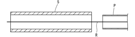
そして、図1に示すように、発泡樹脂によって形成された保温保護管5を既設配管Pの押し込み側端部に隣接して配置し、保温保護管5内に、牽引用線状材としての牽引用ワイヤロープRの一端を挿通しておく。
Then, a pulling wire rope is attached to one end of the leading yarn, the other end of the leading yarn is pulled, and the pulling wire rope is passed through the existing pipe.
Then, as shown in FIG. 1, the heat insulation
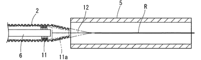
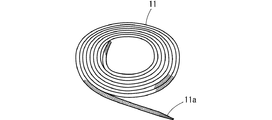
次に、図7に示すような、一端に徐々に縮径する縮径部11aを有する蓄熱材となる密着コイルスプリング11に、図2に示すように、ワイヤロープ12を挿通するとともに、ワイヤロープ12に沿うように4フッ化エチレン樹脂製のチューブ6を挿入する。
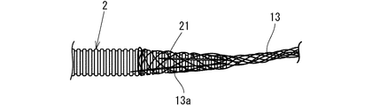
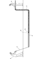
そして、密着コイルスプリング11、ワイヤロープ12およびチューブ6をともに、コルゲート管2に挿入し、図3に示すように、コルゲート管2の牽引側の先端を、その軸方向に数箇所(好ましくは、90°ずつ計4箇所以上)切断し、切断によって形成された短冊状部分21を密着コイルスプリング11の縮径部11aに沿わせた状態で接続ネット13をその上方から被せたのち、接続ネット13を伸長させて、コルゲート管2の上から把持する。
Next, as shown in FIG. 2, the
Then, the close
なお、接続ネット13は、細いワイヤロープが円錐状に編まれて形成され、円錐の中心軸方向に伸長されると縮径して、コルゲート管2の周壁に密着してコルゲート管2の外壁をしっかりと把持するようになっていて、円錐の頂部で、ワイヤロープ12に固定されている。
また、接続ネット13の表面に、接続ネット13の離脱防止、保護および後述する加熱流体としての加熱空気が漏れ出ないようにする塩化ビニル樹脂粘着テープ(図示せず)を巻回する。
The
Further, a vinyl chloride resin adhesive tape (not shown) is wound around the surface of the connection net 13 so that the
そして、ワイヤロープ12の先端を図4に示すように、牽引用ワイヤロープRの一端に固定する。
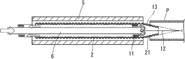
続いて、牽引用ワイヤロープRの他端部を既設配管Pの牽引側の端部から徐々に牽引し、コルゲート管2の先端部を、図5に示すように、密着コイルスプリング11、チューブ6とともに、保温保護管5に導き入れたのち、チューブ6の後端から加熱空気を送り込み、コルゲート管2を内面側から加温する。すなわち、図5に矢印で示すようにチューブ6の後端から送り込まれた加熱空気は、チューブ6先端から、コルゲート管2とチューブ6との間を通り、コルゲート管2および蓄熱体としての密着コイルスプリング11を加温する。
Then, the tip of the
Subsequently, the other end portion of the pulling wire rope R is gradually pulled from the pulling side end portion of the existing piping P, and the tip portion of the
そして、コルゲート管2を熱変形せず可撓性が増す温度まで加温したのち、チューブ6からの加熱空気の供給を続けながら、従来と同様に、図6に示すように、既設配管Pの一端から作業者Aがコルゲート管2を既設配管P内に送り込む動作をしたのち、既設配管Pの他端から作業者Bが牽引用ワイヤロープRを牽引する動作を行うという作業を繰り返し、コルゲート管2を既設配管Pに挿入する。
そして、既設配管Pの他端からコルゲート管2の先端部がある程度突出すれば、接続ネット13による把持を解除したのち、ワイヤロープ12を持って、牽引側から密着コイルスプリング11およびチューブ6を引っ張り、コルゲート管2の内部から引き出すようになっている。
Then, after heating the
If the tip of the
本発明にかかる既設配管へのコルゲート管の挿入工法は、上記の実施の形態に限定されない。たとえば、上記の実施の形態では、チューブもコルゲート管とともに、既設配管内に挿入するようになっていたが、チューブを用いず、コルゲート管の先端から空気が抜けるようにしておき、コルゲート管の後端から加熱空気をコルゲート管内に送り込むだけでコルゲート管を加温するようにしても構わない。 The method for inserting the corrugated pipe into the existing pipe according to the present invention is not limited to the above embodiment. For example, in the above embodiment, the tube is also inserted into the existing pipe together with the corrugated pipe. However, the tube is not used and air is allowed to escape from the tip of the corrugated pipe. The corrugated tube may be heated only by feeding heated air from the end into the corrugated tube.
(実施例1)
ポリエチレン製の二層コルゲート管(外径φ45.5mm、内径φ36mm)を、白ガス管(SGP 50A)とエルボ3個で構成された屋外の既設配管内に挿入を行った。なお、コルゲート管の挿入に際しては、あらかじめ温風によりコルゲート管の表面温度を60℃に加温しておいた。
(Example 1)
A two-layer corrugated pipe made of polyethylene (outer diameter φ45.5 mm, inner diameter φ36 mm) was inserted into an existing outdoor pipe composed of a white gas pipe (SGP 50A) and three elbows. When the corrugated tube was inserted, the surface temperature of the corrugated tube was previously heated to 60 ° C. with warm air.
(実施例2)
コルゲート管の内部に、外径φ35mmのコイルスプリングを挿入した状態であらかじめ温風によりコルゲート管の表面温度を60℃に加温しておいた以外は、実施例1と同様にして屋外の既設配管内にコルゲート管の挿入を行った。
(Example 2)
The existing piping outside in the same manner as in Example 1 except that the surface temperature of the corrugated tube was previously heated to 60 ° C. with warm air with a coil spring having an outer diameter of φ35 mm inserted inside the corrugated tube. A corrugated tube was inserted inside.
(実施例3)
コルゲート管を内径φ55.5mm、φ68mmの中空部を有するポリエチレン製の保温保護管の内部に挿入した状態で予熱しておき、挿入のときには、この保温保護管から順次繰り出しながら、既設配管へ挿入した以外は、実施例2と同様にして屋外の既設配管内にコルゲート管の挿入を行った。
(Example 3)
The corrugated tube is preheated in a state where it is inserted into a polyethylene heat insulating protective tube having a hollow portion with an inner diameter of φ55.5 mm and φ68 mm, and when inserted, the corrugated tube is inserted into the existing piping while being sequentially drawn out from the heat insulating protective tube. The corrugated pipe was inserted into the existing existing pipe in the same manner as in Example 2 except for the above.
(実施例4)
コルゲート管の内部に、外径φ19mm、内径φ12mmの4フッ化エチレン樹脂製のチューブを挿入し、先端部を固定した後、150℃温風をチューブ内に供給して保温保護管内でコルゲート管を加温するとともに、挿入のときには、チューブ内に温風を供給し続けた以外は、実施例2と同様にして屋外の既設配管内にコルゲート管の挿入を行った。
Example 4
Insert a tube made of tetrafluoroethylene resin with an outer diameter of φ19mm and an inner diameter of φ12mm inside the corrugated tube, fix the tip, and then supply 150 ° C hot air into the tube to place the corrugated tube inside the heat insulation protective tube. The corrugated pipe was inserted into the existing existing pipe in the same manner as in Example 2 except that the warm air was kept being supplied into the tube at the time of insertion.
(比較例1)
加温しなかった以外は、実施例1と同様にしてコルゲート管を既設配管に挿入した。
上記実施例1〜4および比較例1の挿入試験をそれぞれ10回ずつ行い、実施例1〜4および比較例1それぞれの挿入完了数、および、挿入状態の評価を加温条件とともに、表1示した。
(Comparative Example 1)
A corrugated pipe was inserted into the existing pipe in the same manner as in Example 1 except that it was not heated.
The insertion tests of Examples 1 to 4 and Comparative Example 1 were performed 10 times each, and the number of completed insertions of Examples 1 to 4 and Comparative Example 1 and the evaluation of the insertion state are shown in Table 1 together with the heating conditions. It was.
上記表1から、コルゲート管を加温しておけば、曲がりの多数ある既設配管であってもうまく挿入が可能であること、特に、保温保護管を設ければより効果があがることがよくわかる。 From Table 1 above, it can be seen that if the corrugated tube is heated, it can be inserted well even with existing piping having a large number of bends. .
P 既設配管
R 牽引用ワイヤロープ(牽引用線状材)
2 コルゲート管
5 保温保護管
6 チューブ
11 密着コイルスプリング(蓄熱体)
P Existing piping R Wire rope for towing (wire material for towing)
2
Claims (4)
Priority Applications (1)
| Application Number | Priority Date | Filing Date | Title |
|---|---|---|---|
| JP2004104025A JP2005291258A (en) | 2004-03-31 | 2004-03-31 | Method for inserting corrugated pipe into existing piping |
Applications Claiming Priority (1)
| Application Number | Priority Date | Filing Date | Title |
|---|---|---|---|
| JP2004104025A JP2005291258A (en) | 2004-03-31 | 2004-03-31 | Method for inserting corrugated pipe into existing piping |
Publications (1)
| Publication Number | Publication Date |
|---|---|
| JP2005291258A true JP2005291258A (en) | 2005-10-20 |
Family
ID=35324432
Family Applications (1)
| Application Number | Title | Priority Date | Filing Date |
|---|---|---|---|
| JP2004104025A Pending JP2005291258A (en) | 2004-03-31 | 2004-03-31 | Method for inserting corrugated pipe into existing piping |
Country Status (1)
| Country | Link |
|---|---|
| JP (1) | JP2005291258A (en) |
-
2004
- 2004-03-31 JP JP2004104025A patent/JP2005291258A/en active Pending
Similar Documents
| Publication | Publication Date | Title |
|---|---|---|
| JPS6334016B2 (en) | ||
| KR0181511B1 (en) | Method for producing a resin pipe for use as the inner lining of existing pipes | |
| JP2005291258A (en) | Method for inserting corrugated pipe into existing piping | |
| CN108139016B (en) | Method and system for manufacturing pre-insulated piping and pre-insulated piping | |
| JPH0533895A (en) | Cap | |
| JP2004041972A (en) | Pig for lining pipe inside and method for lining pipe inside | |
| JP5828051B1 (en) | Multiple pipes and systems for steam recovery from geothermal wells. | |
| JP3417592B2 (en) | Method of forming pipe in conduit | |
| JPS63162221A (en) | Process of lining for pipe | |
| JP2006283903A (en) | New pipe installation method | |
| JP3447417B2 (en) | How to draw lining material into pipeline | |
| JPH10193427A (en) | Manufacture of double pipe | |
| JP4881091B2 (en) | Hot water floor heating conduit material | |
| JP4854022B2 (en) | Insulated hose and manufacturing method thereof | |
| JPH07178816A (en) | Inserting resin pipe used for repair of existing pipeline and repairing thechniqe thereof | |
| JP2012237360A (en) | Implement for pipe traction and method of arranging new pipe in existing pipe by using the same | |
| JP3699333B2 (en) | Repair method for existing pipelines | |
| JP2007225402A (en) | Gas detection needle | |
| JPH11280957A (en) | Water supply and hot-water supply hose | |
| JPH07178815A (en) | Inserting resin pipe used for repair of existing pipeline, and repairing technique of existing pipeline used therewith | |
| JP3276425B2 (en) | cap | |
| JP2005291257A (en) | Method for inserting corrugated pipe into existing piping | |
| JP2005121108A (en) | Pipe for water/hot water supply | |
| JPH02202432A (en) | Inner face lining method of pipe and pipe for lining | |
| JP2006046591A (en) | Water stopping method of attachment port and diameter-expanded member used in the same |
Legal Events
| Date | Code | Title | Description |
|---|---|---|---|
| A621 | Written request for application examination |
Effective date: 20061115 Free format text: JAPANESE INTERMEDIATE CODE: A621 |
|
| A977 | Report on retrieval |
Effective date: 20090806 Free format text: JAPANESE INTERMEDIATE CODE: A971007 |
|
| A131 | Notification of reasons for refusal |
Free format text: JAPANESE INTERMEDIATE CODE: A131 Effective date: 20090811 |
|
| A02 | Decision of refusal |
Effective date: 20091208 Free format text: JAPANESE INTERMEDIATE CODE: A02 |