JP2005291257A - Method for inserting corrugated pipe into existing piping - Google Patents
Method for inserting corrugated pipe into existing piping Download PDFInfo
- Publication number
- JP2005291257A JP2005291257A JP2004104024A JP2004104024A JP2005291257A JP 2005291257 A JP2005291257 A JP 2005291257A JP 2004104024 A JP2004104024 A JP 2004104024A JP 2004104024 A JP2004104024 A JP 2004104024A JP 2005291257 A JP2005291257 A JP 2005291257A
- Authority
- JP
- Japan
- Prior art keywords
- pipe
- corrugated
- corrugated pipe
- pulling
- gripping
- Prior art date
- Legal status (The legal status is an assumption and is not a legal conclusion. Google has not performed a legal analysis and makes no representation as to the accuracy of the status listed.)
- Pending
Links
Images

Abstract
Description
本発明は、老朽化した既設配管の内部に新たな管路としてコルゲート管を挿入して更新する工法に関する。 The present invention relates to a method for renewing a corrugated pipe by inserting a corrugated pipe as a new pipe inside an aged existing pipe.
ガスや水道の既設配管が老朽化した場合、地面等を掘削して配管を新しく交換する代わりに、既設配管内に可撓性のあるコルゲート管を挿入し、このコルゲート管を新しい配管として使用する方法が行われている。 When the existing pipes for gas and water are aged, instead of excavating the ground and replacing the pipes, insert a flexible corrugated pipe into the existing pipe and use this corrugated pipe as a new pipe. The way is done.
この既設配管へのコルゲート管の挿入工法としては、既設配管の一方の開口端から他方の開口端まで挿通された牽引用の線状材に、樹脂製のコルゲート管の先端を既設配管の一方の開口端側で固定したのち、既設配管の他方の開口端側から前記線状材を牽引する牽引動作と、既設配管の一方の開口端側からコルゲート管を既設配管内に押し込む押し込み動作とを行い、既設配管内にコルゲート管を挿入する工法(たとえば、特許文献1参照)が既に提案されている。
また、この工法では、コルゲート管の牽引は、まず、コルゲート管を挿入しようとする既設配管の一端から他端に向かって牽引用ワイヤロープを挿入し、コルゲート管の内壁面に形成された凹溝に牽引治具の凸部を係止させた状態で牽引治具に牽引用ワイヤロープの一端を固定し、他端から牽引するようにしている。
As a method of inserting the corrugated pipe into the existing pipe, the tip of the resin corrugated pipe is inserted into one of the existing pipes on the pulling linear member inserted from one open end of the existing pipe to the other open end. After fixing at the open end side, perform the pulling operation to pull the linear material from the other open end side of the existing pipe, and push-in operation to push the corrugated pipe into the existing pipe from the one open end side of the existing pipe A method of inserting a corrugated pipe into an existing pipe has already been proposed (for example, see Patent Document 1).
In this construction method, the corrugated pipe is pulled first by inserting a pulling wire rope from one end of the existing pipe to which the corrugated pipe is to be inserted toward the other end, and a concave groove formed on the inner wall surface of the corrugated pipe. One end of the pulling wire rope is fixed to the pulling jig in a state where the convex portion of the pulling jig is locked to the pulling jig, and is pulled from the other end.
しかし、上記のような牽引方法では、コルゲート管の内面の凹凸形状によって治具の形状が大いに制約される。
すなわち、牽引治具は、凸部がコルゲート管の凹溝に入り込む形状とする必要があるが、このとき凸部の大きさが小さい場合には牽引によって牽引治具が容易に抜けてしまう。特に曲がり部などでコルゲート管が伸縮変形をするときに抜けやすい。また、抜けなくてもコルゲート管が拡径しようとするために、コルゲート管の外径が拡大し、摩擦抵抗が増加する恐れがある。
However, in the pulling method as described above, the shape of the jig is greatly restricted by the uneven shape of the inner surface of the corrugated tube.
That is, the traction jig needs to have a shape in which the convex portion enters the concave groove of the corrugated tube, but if the size of the convex portion is small at this time, the traction jig is easily pulled out by traction. In particular, the corrugated tube tends to come off when it expands and contracts at a bent portion. Further, since the corrugated tube attempts to expand the diameter even if it does not come off, the outer diameter of the corrugated tube may increase and the frictional resistance may increase.
これらを防ぐために、牽引治具とコルゲート管との嵌合長さを長くすれば、曲がり部での通過が困難になる。特に挿入後の配管の圧力損失の増加を小さくするために、コルゲート管の内外径をできるだけ大きくした場合には、牽引治具の内径も大きくなり、場合によっては挿入が不可能になる。 In order to prevent these, if the fitting length between the traction jig and the corrugated pipe is increased, it becomes difficult to pass through the bent portion. In particular, when the inner and outer diameters of the corrugated pipe are made as large as possible in order to reduce the increase in pressure loss of the pipe after insertion, the inner diameter of the traction jig also increases, and in some cases, the insertion becomes impossible.
本発明は、上記事情に鑑みて、既設配管とコルゲート管とのクリアランスが少なく、曲がりが多い配管であっても、また、コルゲート管の管径が内外面形状に関係なく、スムースにコルゲート管を牽引することができる既設配管へのコルゲート管の挿入工法を提供することを目的としている。 In view of the above circumstances, the present invention provides a smooth corrugated pipe regardless of the shape of the inner and outer surfaces of the pipe with a small clearance between the existing pipe and the corrugated pipe and a large bend. The object is to provide a method for inserting a corrugated pipe into an existing pipe that can be pulled.
上記目的を達成するために、本発明の請求項1に記載の既設配管へのコルゲート管の挿入工法(以下、「請求項1の挿入工法」と記す)は、既設配管の一方の開口端から他方の開口端まで挿通された牽引用線状材に、樹脂製のコルゲート管の先端を既設配管の一方の開口端側で固定したのち、既設配管の他方の開口端側から前記牽引用線状材を牽引する牽引動作と、既設配管の一方の開口端側からコルゲート管を既設配管内に押し込む押し込み動作とを行い、既設配管内にコルゲート管を挿入する既設配管へのコルゲート管の挿入工法において、線状材を一方が開口した筒状あるいは円錐状に編むことによって形成された把持部を有し、この把持部が伸長されるとその内径が縮径する把持部材を、把持部の開口端以外の部分で前記牽引用線状材に固定し、前記把持部の開口端からコルゲート管の牽引方向の先端部を把持部内に挿入したのち、把持部を伸長させて縮径させ、把持部内壁面をコルゲート管の外周面に圧接係止させてコルゲート管を把持部材の把持部で把持した状態で牽引用線状材を牽引することを特徴としている。 In order to achieve the above object, the corrugated pipe insertion method (hereinafter referred to as “insertion method of claim 1”) into the existing pipe according to claim 1 of the present invention is performed from one open end of the existing pipe. After fixing the tip of the resin corrugated pipe on one opening end side of the existing piping to the pulling linear material inserted to the other opening end, the pulling linear shape from the other opening end side of the existing piping In the method of inserting the corrugated pipe into the existing pipe that pulls the corrugated pipe into the existing pipe by pulling the corrugated pipe into the existing pipe from the opening end side of the existing pipe and pulling the corrugated pipe A gripping member formed by knitting a linear member into a cylindrical or conical shape with one open, and a gripping member whose inner diameter is reduced when the gripping portion is extended, The towed line in the part other than The tip of the corrugated tube in the pulling direction is inserted into the gripping portion from the opening end of the gripping portion, and then the gripping portion is extended to reduce the diameter, and the inner wall surface of the gripping portion is pressed against the outer peripheral surface of the corrugated tube Thus, the towed linear member is pulled while the corrugated tube is held by the holding portion of the holding member.
本発明の請求項2に記載の既設配管へのコルゲート管の挿入工法(以下、「請求項2の挿入工法」と記す)は、請求項1の挿入工法において、コルゲート管の少なくとも把持部によって把持される部分で、コルゲート管より可撓性の大きい芯材をコルゲート管内に配置させた状態でコルゲート管を把持部で把持することを特徴としている。
芯材は、特に限定されないが、コルゲート管の全長にわたってコルゲート管内に挿入されていることが好ましい。
The method for inserting a corrugated pipe into an existing pipe according to
Although a core material is not specifically limited, It is preferable that it is inserted in the corrugated pipe over the full length of the corrugated pipe.
本発明の請求項3に記載の既設配管へのコルゲート管の挿入工法(以下、「請求項3の挿入工法」と記す)は、請求項2の挿入工法において、コルゲート管の把持部によって把持される部分の管壁を管軸方向に複数箇所で切断して、複数の短冊状部を形成し、この短冊状部を芯材の縮径部の表面に沿わせた状態で、コルゲート管を把持部で把持することを特徴としている。
The method for inserting a corrugated pipe into an existing pipe according to
本発明の請求項4に記載の既設配管へのコルゲート管の挿入工法(以下、「請求項4の挿入工法」と記す)は、請求項2または請求項3の挿入工法において、芯材が密着コイルスプリングであることを特徴としている。
密着コイルスプリングとは、無負荷状態では、コイルを構成するワイヤの各ループの壁面が密着しており、軸方向に圧縮されてもその長さが略変わらず、径方向に力を受けても、少しの力では直径が略変わらないものをいう。
The method for inserting a corrugated pipe into an existing pipe according to claim 4 of the present invention (hereinafter referred to as “inserting method of claim 4”) is the core construction in which It is a coil spring.
In the no-load state, the close contact coil spring is such that the wall surface of each loop of the wire that constitutes the coil is in close contact, and its length does not change substantially even if it is compressed in the axial direction. The one whose diameter does not change with a little force.
本発明の請求項5に記載の既設配管へのコルゲート管の挿入工法(以下、「請求項5の挿入工法」と記す)は、請求項2〜請求項4のいずれかの挿入工法において、芯材が牽引方向に向かって徐々に縮径していることを特徴としている。
The method for inserting a corrugated pipe into an existing pipe according to claim 5 of the present invention (hereinafter referred to as “insertion method of claim 5”) is the core of any one of
本発明の請求項6に記載の既設配管へのコルゲート管の挿入工法(以下、「請求項5の挿入工法」と記す)は、請求項1〜請求項5のいずれかの挿入工法において、把持状態で把持部の外周面を可撓性を有する保護被膜で被覆することを特徴としている。
請求項6の挿入工法のおいて、保護被膜としては、特に限定されないが、ゴム、エラストマー、ポリ塩化ビニル樹脂、4フッ化エチレン樹脂など、屈曲部で曲がりやすさを阻害しない材質のものが好ましい。また、形状としては接続部の可撓性を損なわない程度の肉厚で、牽引時にはがれてしまわない程度のものであればよく、テープ状のものを巻き付けたり、円筒状のものをかぶせてもよい。
The method for inserting a corrugated pipe into an existing pipe according to claim 6 of the present invention (hereinafter referred to as “insertion method of claim 5”) is the gripping method according to any one of claims 1 to 5. In this state, the outer peripheral surface of the gripping part is covered with a flexible protective film.
In the insertion method according to claim 6, the protective film is not particularly limited, but is preferably made of a material that does not hinder bending at the bent portion, such as rubber, elastomer, polyvinyl chloride resin, and tetrafluoroethylene resin. . Also, the shape should be thick enough not to impair the flexibility of the connection, and it should not fall off when towed. It can be wrapped around a tape or covered with a cylindrical shape. Also good.
本発明において、把持部を構成する線状材および牽引用線状材としては、特に限定されないが、ワイヤ、ワイヤロープ、樹脂製ロープ等が挙げられ、ワイヤロープが好ましい。
本発明の挿入工法に用いられるコルゲート管は、一層のものでも構わないが、断面波形をした蛇腹状の外層管状部と、この外層管状部に内嵌された状態で、外層管状部と同じピッチの断面波形をした蛇腹状の内層管状部とを有し、外層管状部と、内層管状部とが、断面波形の谷部にあたる部分のみで一体化されている合成樹脂製二層コルゲート管を用いることが好ましい。
In the present invention, the linear material and the traction linear material constituting the gripping part are not particularly limited, and examples thereof include a wire, a wire rope, a resin rope, and the like, and a wire rope is preferable.
The corrugated tube used in the insertion method of the present invention may be a single layer, but the corrugated outer layer tubular portion having a corrugated cross section and the same pitch as the outer layer tubular portion in the state fitted inside the outer layer tubular portion. A synthetic resin double-layer corrugated tube having an accordion-shaped inner-layer tubular portion having a corrugated cross-sectional shape, wherein the outer-layer tubular portion and the inner-layer tubular portion are integrated only at a portion corresponding to a trough portion of the corrugated cross-section. It is preferable.
本発明にかかる既設配管へのコルゲート管の挿入工法は、以上のように、線状材が一方が開口した筒状あるいは円錐状に編まれた把持部を有し、この把持部が伸長されるとその内径が縮径する把持部材を、把持部の開口端以外の部分で前記牽引用線状材に固定し、前記把持部の開口端からコルゲート管の牽引方向の先端部を把持部内に挿入したのち、把持部を伸長させて縮径させ、把持部内壁面をコルゲート管の外周面に圧接係止させてコルゲート管を把持部材の把持部で把持した状態で牽引用線状材を牽引するようにしたので、牽引時の引っ張り力が増加するほど、把持部材の把持部が伸長状態になって縮径し、把持部材の把持部がコルゲート管外面に圧接係止され、コルゲート管外面への把持力が増大する。したがって、引っ張り力が大きくなっても把持部材がコルゲート管からはずれたりすることがなく、スムースに牽引動作を行うことができる。 As described above, the method for inserting a corrugated pipe into an existing pipe according to the present invention has a gripping portion in which a linear material is knitted into a cylindrical shape or a conical shape, and the gripping portion is extended. And the gripping member whose inner diameter is reduced is fixed to the traction wire material at a portion other than the opening end of the gripping portion, and the tip end portion of the corrugated pipe in the pulling direction is inserted into the gripping portion from the opening end of the gripping portion. After that, the gripping part is extended and contracted, the inner wall surface of the gripping part is pressed against and locked to the outer peripheral surface of the corrugated pipe, and the towing linear material is pulled while the corrugated pipe is gripped by the gripping part of the gripping member. Therefore, as the pulling force during towing increases, the gripping part of the gripping member expands and contracts in diameter, and the gripping part of the gripping member is pressed and locked to the outer surface of the corrugated pipe, Power increases. Therefore, even if the pulling force is increased, the gripping member is not detached from the corrugated tube, and the traction operation can be performed smoothly.
また、把持部材が線状材を筒状に編むことによって形成されているので、把持部材自体が可撓性を備えている。したがって、コルゲート管の把持部および把持部材は少ない抵抗で既設配管の曲がり部を通過することができる。 Further, since the gripping member is formed by knitting a linear material into a cylindrical shape, the gripping member itself has flexibility. Therefore, the grip part and the grip member of the corrugated pipe can pass through the bent part of the existing pipe with a small resistance.
請求項2の挿入工法は、コルゲート管の少なくとも把持部によって把持される部分で、コルゲート管より可撓性の大きい芯材をコルゲート管内に配置させた状態でコルゲート管を把持部で把持するようにしたので、コルゲート管の壁面が、把持部材の把持部と、芯材との間に挟まれて、コルゲート管がよりしっかりと把持部材の把持部によって把持される。しかも、芯材が、コルゲート管より可撓性の大きいので、既設配管の曲がり部に沿って容易に変形し、少ない抵抗で既設配管の曲がり部を通過することができる。
The insertion method of
請求項3の挿入工法は、コルゲート管の把持部によって把持される部分の管壁を管軸方向に複数箇所で切断して、複数の短冊状部を形成し、この短冊状部を芯材の縮径部の表面に沿わせた状態で、コルゲート管を把持部で把持するようにしたので、コルゲート管の把持部材によって把持される部分の内径と、芯材の外径とに差があっても、コルゲート管の把持部において、コルゲート管と芯材との間に隙間がない状態で把持部材によって把持ができ、よりしっかりとした把持状態が得られる。
In the insertion method of
請求項4の挿入工法は、芯材が密着コイルスプリングであるので、無負荷状態では、コイルを構成するワイヤの各ループの壁面が密着しており、軸方向に圧縮されてもその長さが略変わらず、径方向に力を受けても、少しの力では直径が略変わらない。したがって、この密着コイルスプリングをコルゲート管の全長にわたって挿入しておくと、押し込み動作時に、密着コイルスプリングがコルゲート管の圧縮方向の変形および半径方向の変形を抑えることができる。 In the insertion method according to claim 4, since the core material is a contact coil spring, the wall surfaces of the loops of the wires constituting the coil are in close contact with each other in the no-load state, and the length of the wire is compressed even in the axial direction. Even if a force is applied in the radial direction, the diameter does not change substantially with a slight force. Therefore, if the close contact coil spring is inserted over the entire length of the corrugated tube, the close contact coil spring can suppress deformation in the compression direction and radial direction of the corrugated tube during the pushing operation.
請求項5の挿入工法は、芯材が牽引方向に向かって徐々に縮径しているので、コルゲート管をこの縮径部に沿うように変形させれば、曲がり部や既設管路とのクリアランスが小さい場合でも、牽引の抵抗を減少することができる。 In the insertion method of claim 5, since the core material is gradually reduced in diameter in the pulling direction, if the corrugated pipe is deformed along the reduced diameter part, the clearance from the bent part or the existing pipe line is obtained. Even when is small, traction resistance can be reduced.
請求項6の挿入工法は、把持状態で把持部の外周面を可撓性を有する保護被膜で被覆するようにしたので、既設管との摩擦抵抗を低下させることができる。また、コルゲート管の端部に短冊状部分を形成した場合、把持部の網目から短冊状部分が飛び出ることも防止できる。 In the insertion method according to the sixth aspect, since the outer peripheral surface of the gripping portion is covered with a flexible protective film in the gripping state, the frictional resistance with the existing pipe can be reduced. Moreover, when a strip-shaped part is formed in the edge part of a corrugated pipe, it can also prevent that a strip-shaped part jumps out from the mesh of a holding part.
以下に、本発明を、その実施の形態をあらわす図面を参照しつつ詳しく説明する。
図1〜図3は、本発明にかかる既設配管へのコルゲート管の挿入工法の1つの実施の形態を工程順にあらわしている。
Hereinafter, the present invention will be described in detail with reference to the drawings showing embodiments thereof.
1 to 3 show one embodiment of a method for inserting a corrugated pipe into an existing pipe according to the present invention in the order of steps.
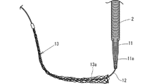
この挿入工法は、図1に示すように、まず、一端が徐々に縮径している縮径部11aを備える芯材としての密着コイルスプリング11をワイヤロープ12を内部に挿入した状態でコルゲート管2の内部に挿入する。
また、ワイヤロープ12の縮径部11a側から延出した部分に把持部材13を固定しておく。
In this insertion method, as shown in FIG. 1, first, a corrugated tube with a close
In addition, the
把持部材13は、図1に示すように、細いワイヤロープが円錐状に編まれて形成され、円錐の底面側が開口した把持部13aを有し、把持部13aが円錐の中心軸方向に伸長されると縮径して、コルゲート管2の周壁に密着してコルゲート管2の外壁をしっかりと把持するようになっていて、把持部13aの円錐の頂部で、ワイヤロープ12に固定される。
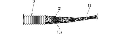
つぎに、図2に示すように、コルゲート管2の先端部をカッター等によって放射状に管軸方向に4箇所以上で切断して複数の把短冊状部分21を形成する。
As shown in FIG. 1, the
Next, as shown in FIG. 2, the tip of the
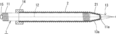
そして、図2および図3に示すように、把短冊状部分21をコルゲート管2の中心軸方向を撓ませて、密着コイルスプリング11の縮径部11aの外面に沿わせたのち、把持部材13の把持部13aの開口を拡げて、コルゲート管2の外側から被せたのち、把持部13aを円錐の中心軸方向に伸長させて、開口部を縮径させ、把持部13aによって、コルゲート管2の把短冊状部分21を密着コイルスプリング11の縮径部11aとの間でしっかりと挟み込み、把持状態にする。
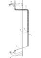
続いて、図4に示すように、保護被膜となる塩化ビニル樹脂粘着テープ3を把持部13aの上から螺旋状に巻き付けたのち、塩化ビニル樹脂粘着テープ3の上からグリスを塗布する。
2 and 3, after the
Subsequently, as shown in FIG. 4, after the vinyl chloride resin
なお、図3に示すように、コルゲート管2の他端とコイルスプリング11とを、コイルスプリンブ11の他端とワイヤロープ12とを、それぞれ固定部材14、15によって固定しておくことが好ましい。
このようにして、コルゲート管2に把持部材13を装着したのち、図示していないが、まず、先導糸の先端に落下傘状の風圧受け具を取り付け、風圧受け具を既設配管の一端に挿入したのち、コンプレッサ等で圧縮空気を既設配管の一端から他端に向けて送り、風圧受け具を圧縮空気によって既設配管の他端に送ることによって、先導糸を既設配管内に通す。
In addition, as shown in FIG. 3, it is preferable to fix the other end of the
Thus, after attaching the gripping
そして、先導糸の一端に牽引用ワイヤロープを取り付け、先導糸の他端を引っ張り、既設配管に牽引用ワイヤロープを通す。
つぎに、既設配管の一方の端部からでた牽引用ワイヤロープの一端を、縮径部11aから延出したワイヤロープ12の先端に固定し、図5に示すように、既設配管Pの一端から作業者Aがコルゲート管2を既設配管P内に送り込む動作をしたのち、既設配管Pの他端から作業者Bが牽引用ワイヤロープRを牽引する動作を行うという作業を繰り返し、コルゲート管2を既設配管Pに挿入する。
Then, a pulling wire rope is attached to one end of the leading yarn, the other end of the leading yarn is pulled, and the pulling wire rope is passed through the existing pipe.
Next, one end of the pulling wire rope from one end of the existing pipe is fixed to the tip of the
そして、既設配管Pの他端からコルゲート管2の先端部がある程度突出すれば、塩化ビニル樹脂粘着テープ3を取り除き、把持部材13を取り外し、必要に応じて、コルゲート管2の他端とコイルスプリング11との固定を解除したのち、ワイヤロープ12を持って、牽引側から密着コイルスプリング11を引っ張り、コルゲート管2の内部から引き出すようになっている。
And if the front-end | tip part of the corrugated pipe |
本発明にかかる既設配管へのコルゲート管の挿入工法は、上記の実施の形態に限定されない。たとえば、上記の実施の形態では、芯材となる密着コイルスプリングがコルゲート管の全長にわたってコルゲート管内に挿入されていたが、芯材は、把持部材の把持部で把持される部分のみ、コルゲート管内に挿入されていても構わない。 The method for inserting the corrugated pipe into the existing pipe according to the present invention is not limited to the above embodiment. For example, in the above embodiment, the close contact coil spring as the core material is inserted into the corrugated tube over the entire length of the corrugated tube, but only the portion gripped by the gripping portion of the gripping member is in the corrugated tube. It does not matter if it is inserted.
図1に示すような把持部材13をコルゲート管2の先端を把持部13aで把持するように装着するとともに、把持部材の先端に牽引用ワイヤロープを接続して、牽引用ワイヤロープRを牽引する牽引する牽引動作と、コルゲート管2を押し込む押し込み動作とを繰り返し、25Aの鋼管製配管内にコルゲート管2を挿入したところ、エルボが5個ある配管であっても、問題なくコルゲート管2を挿入することができた。
A gripping
コルゲート管の先端を4カ所切り、把短冊状部分21を形成するとともに、図3および図4に示すように密着コイルスプリング11の縮径部11aに短冊状部分を沿わせた状態で把持部材13の把持部13aで把短冊状部分21を把持した状態で、上記実施例1と同様にして、25Aの鋼管製配管内にコルゲート管2を挿入したところ、エルボ4個とベンド4個を含む配管に挿通することができたが、把短冊状部分21の一部が、把持部13aの網目部分から飛び出していた。
The tip of the corrugated tube is cut at four points to form a narrow strip-shaped
実施例2のようにして把持部材13の把持部13aで把短冊状部分21を把持したのち、図5に示すように、塩化ビニル樹脂粘着テープ3を把持部13aの上から螺旋状に巻き付けたのち、塩化ビニル樹脂粘着テープ3の上からグリスを塗布した状態で、上記実施例2と同様にして、25Aの鋼管製配管内にコルゲート管2を挿入したところ、エルボ4個とベンド4個を含む配管に挿通することかができた。
また、挿入後、把持部付近の外観を調べたが、先端の塩化ビニル樹脂粘着テープ3にはこすれによる傷があるが、把持部材13およびコルゲート管2には損傷がなかった。また引き込み荷重も減少していた。
After gripping the strip-shaped
Further, after the insertion, the appearance in the vicinity of the gripping portion was examined. The vinyl chloride resin
P 既設配管
R 牽引用ワイヤロープ(牽引用線状材)
2 コルゲート管
21 短冊状部分
3 塩化ビニル樹脂粘着テープ(保護被膜)
11 密着コイルスプリング(芯材)
11a 縮径部
13 把持部材
13a 把持部
P Existing piping R Wire rope for towing (wire material for towing)
2
11 Adhesive coil spring (core material)
11a Reduced
Claims (6)
Priority Applications (1)
| Application Number | Priority Date | Filing Date | Title |
|---|---|---|---|
| JP2004104024A JP2005291257A (en) | 2004-03-31 | 2004-03-31 | Method for inserting corrugated pipe into existing piping |
Applications Claiming Priority (1)
| Application Number | Priority Date | Filing Date | Title |
|---|---|---|---|
| JP2004104024A JP2005291257A (en) | 2004-03-31 | 2004-03-31 | Method for inserting corrugated pipe into existing piping |
Publications (1)
| Publication Number | Publication Date |
|---|---|
| JP2005291257A true JP2005291257A (en) | 2005-10-20 |
Family
ID=35324431
Family Applications (1)
| Application Number | Title | Priority Date | Filing Date |
|---|---|---|---|
| JP2004104024A Pending JP2005291257A (en) | 2004-03-31 | 2004-03-31 | Method for inserting corrugated pipe into existing piping |
Country Status (1)
| Country | Link |
|---|---|
| JP (1) | JP2005291257A (en) |
-
2004
- 2004-03-31 JP JP2004104024A patent/JP2005291257A/en active Pending
Similar Documents
| Publication | Publication Date | Title |
|---|---|---|
| US4453291A (en) | Grip for pulling fiber optic cable | |
| US5480203A (en) | Pulling tool for pulling connectorized cable | |
| US6974169B1 (en) | Pulling grip with shroud | |
| JPH078194B2 (en) | Fishing line guide member for hollow fishing rod and method of manufacturing the same | |
| JP2005291257A (en) | Method for inserting corrugated pipe into existing piping | |
| KR100773083B1 (en) | Multiple pipe for cable | |
| JP4833524B2 (en) | Water supply hose fitting structure | |
| JP5743278B2 (en) | Diameter expansion method for cold shrink tube | |
| JP2005291255A (en) | Method for inserting corrugated pipe into existing piping and insertion support fixture used for the inserting method | |
| JP2005130547A (en) | Wire net type pulling eye for cable traction | |
| JP2008002498A (en) | Grommet | |
| US7257889B1 (en) | Method for inserting wires through braided shielding | |
| JPH0444529Y2 (en) | ||
| JP4118287B2 (en) | Elastomer tubular body mounting method | |
| JP3086205B2 (en) | Pressure hose | |
| JP2005291254A (en) | Synthetic resin two-layered corrugated pipe, and repair method of pipe for inserting the same corrugated pipe into overaged existing piping | |
| JP3751999B2 (en) | Expanding holder for tubular members | |
| JP2012047191A (en) | Metal joint | |
| JP2004129361A (en) | Cable passing jig | |
| JP3059573U (en) | Nominal line storage case | |
| JP2004084718A (en) | Buried pipe extraction tool | |
| JP2018168945A (en) | Attachment for tool insertion | |
| JP4092698B2 (en) | Terminal cap | |
| JP2021126830A (en) | Belt-like member for existing pipe rehabilitation and method for existing pipe rehabilitation | |
| JP2012147668A (en) | Cable insertion method |
Legal Events
| Date | Code | Title | Description |
|---|---|---|---|
| A621 | Written request for application examination |
Effective date: 20061115 Free format text: JAPANESE INTERMEDIATE CODE: A621 |
|
| A977 | Report on retrieval |
Free format text: JAPANESE INTERMEDIATE CODE: A971007 Effective date: 20090806 |
|
| A131 | Notification of reasons for refusal |
Free format text: JAPANESE INTERMEDIATE CODE: A131 Effective date: 20090811 |
|
| A02 | Decision of refusal |
Effective date: 20091208 Free format text: JAPANESE INTERMEDIATE CODE: A02 |