JP2005291255A - Method for inserting corrugated pipe into existing piping and insertion auxiliary jig used for this method - Google Patents
Method for inserting corrugated pipe into existing piping and insertion auxiliary jig used for this method Download PDFInfo
- Publication number
- JP2005291255A JP2005291255A JP2004104022A JP2004104022A JP2005291255A JP 2005291255 A JP2005291255 A JP 2005291255A JP 2004104022 A JP2004104022 A JP 2004104022A JP 2004104022 A JP2004104022 A JP 2004104022A JP 2005291255 A JP2005291255 A JP 2005291255A
- Authority
- JP
- Japan
- Prior art keywords
- pipe
- coil spring
- corrugated
- corrugated pipe
- existing
- Prior art date
- Legal status (The legal status is an assumption and is not a legal conclusion. Google has not performed a legal analysis and makes no representation as to the accuracy of the status listed.)
- Pending
Links
Images

Landscapes
- Protection Of Pipes Against Damage, Friction, And Corrosion (AREA)
Abstract
【課題】押し込み動作と牽引動作とを繰り返す工法においてコルゲート管を傷めることがなく、コルゲート管をスムースに既設配管に挿入することが出来る既設配管へのコルゲート管の挿入工法およびこの工法に用いる挿入補助治具を提供することを目的としている。
【解決手段】牽引動作と、押し込み動作とを行い、既設配管内にコルゲート管を挿入する既設配管へのコルゲート管の挿入工法において、コルゲート管より小径かつ可撓性に富んだ密着コイルスプリングをコルゲート管に挿入した状態で、コルゲート管とともに密着コイルスプリングを前記線状材で牽引し、かつ、コルゲート管とともに密着コイルスプリングを既設配管に送り込んで、コルゲート管を既設配管内に挿入したのち、密着コイルスプリングを既設配管のいずれか一方から引き抜くことを特徴としている。
【選択図】 図1An object of the present invention is to insert a corrugated pipe into an existing pipe that can smoothly insert the corrugated pipe into an existing pipe without damaging the corrugated pipe in a method of repeating the pushing operation and the pulling operation, and an insertion assist used in this method. The purpose is to provide a jig.
In a method for inserting a corrugated pipe into an existing pipe that performs a pulling action and a pushing action and inserting the corrugated pipe into the existing pipe, a corrugated coil spring having a smaller diameter and more flexibility than the corrugated pipe is provided. In the state of being inserted into the pipe, pull the close contact coil spring with the linear material together with the corrugated pipe, and feed the close contact coil spring together with the corrugate pipe into the existing pipe and insert the corrugate pipe into the existing pipe, It is characterized by pulling out the spring from one of the existing pipes.
[Selection] Figure 1
Description
本発明は、老朽化した既設管の内部に新たな管路としてコルゲート管を挿入して更新する工法およびこの工法に用いる挿入補助治具に関する。 The present invention relates to a method of inserting and renewing a corrugated pipe as a new pipe line inside an aged existing pipe, and an insertion auxiliary jig used in this method.
ガスや水道の既設配管が老朽化した場合、地面等を掘削して配管を新しく交換する代わりに、既設配管内に可撓性のあるコルゲート管を挿入し、このコルゲート管を新しい配管として使用する方法が行われている。
この既設配管へのコルゲート管の挿入工法としては、既設配管の一端から他端に向けてコルゲート管を押し込んでいく工法(たとえば、特許文献1参照)、あるいは、既設配管の一方の開口端から他方の開口端まで挿通された牽引用の線状材に、樹脂製のコルゲート管の先端を既設配管の一方の開口端側で固定したのち、既設配管の他方の開口端側から前記線状材を牽引する牽引動作と、既設配管の一方の開口端側からコルゲート管を既設配管内に押し込む押し込み動作とを行い、既設配管内にコルゲート管を挿入する工法(たとえば、特許文献2参照)が既に提案されている。
When the existing pipes for gas and water are aged, instead of excavating the ground and replacing the pipes, insert a flexible corrugated pipe into the existing pipe and use this corrugated pipe as a new pipe. The way is done.
As a method of inserting the corrugated pipe into the existing pipe, a method of pushing the corrugated pipe from one end of the existing pipe to the other end (see, for example, Patent Document 1), or from one open end of the existing pipe to the other After fixing the tip of the resin corrugated pipe on one opening end side of the existing piping to the pulling linear material inserted to the opening end of the existing piping, the linear material is attached from the other opening end side of the existing piping. A construction method (for example, refer to Patent Document 2) in which a corrugated pipe is inserted into an existing pipe by performing a pulling action to pull and a pushing action of pushing the corrugated pipe into the existing pipe from one open end side of the existing pipe has already been proposed. Has been.
ところで、上記特許文献1の工法では、既設配管の一端からコルゲート管をスプリング・ガイドと同時に挿入し、コルゲート管の先端から突出したスプリング・ガイドを曲がり部を挿通する際のガイドとしながら、曲がりのある配管へコルゲート管を押し込んでいくようにしている。
本発明者らの検討によれば、コルゲート管の挿入工法においては、曲がりが存在する配管にコルゲート管を挿入する場合には、コルゲート管を押し込んでいく方法が最も有効であるものの、曲がりが多くある配管形態(特に日本の既設配管には多い)においては、この工法を用いる場合、負荷が大きすぎて現実的な使用は困難であることがわかった。
By the way, in the construction method of Patent Document 1, the corrugated tube is inserted simultaneously with the spring guide from one end of the existing pipe, and the spring guide protruding from the tip of the corrugated tube is used as a guide for inserting the bent portion, The corrugated pipe is pushed into a certain pipe.
According to the study by the present inventors, in the corrugated tube insertion method, when the corrugated tube is inserted into a pipe where there is a bend, the method of pushing the corrugated tube is most effective, but there are many bends. In some piping forms (especially in existing Japanese piping), it was found that when this method was used, the load was too great and practical use was difficult.
一方、特許文献2の工法で、コルゲート管を既設配管の一端から他端に向かって押し込む押し込み動作と、コルゲート管の先端を牽引ロープで既設配管の他端から牽引する牽引動作とを交互に繰り返すことによって、曲がりが多くある配管形態に対応させるようにしている。
しかしながら、上記のように、押し込み動作と牽引動作とを繰り返す工法は、押し込み動作の途中でコルゲート管の先端が曲がり部に達し、先端が曲がり部でつかえたりした場合でも、タイミングよく牽引動作を行えば、スムースにコルゲート管を既設配管に挿入することができるのであるが、タイミングがあわず、コルゲート管を押し込みすぎると、コルゲート管が途中で座屈するなどの弊害がでる恐れがある。そして、座屈によって、コルゲート管が破損しガス漏れが生じたり、破損しないまでもコルゲート管内に突出部が生じ、この突出部により圧損が大きくなるという問題がでる。また、牽引の際にコルゲート管が屈曲部で偏平に変形する恐れもある。
On the other hand, in the construction method of
However, as described above, the method of repeating the pushing operation and the towing operation performs the towing operation in a timely manner even when the tip of the corrugated tube reaches the bent portion during the pushing operation and the tip is held by the bent portion. For example, the corrugated pipe can be smoothly inserted into the existing pipe, but there is a possibility that the corrugated pipe will buckle in the middle if the corrugated pipe is pushed too much because the timing is not right. Then, due to buckling, the corrugated tube is broken to cause gas leakage, or a protruding portion is generated in the corrugated tube even if it is not damaged, and the pressure loss is increased by this protruding portion. In addition, the corrugated tube may be deformed flat at the bent portion during towing.
そこで、特許文献2の工法では、押し込み操作力がコルゲート管の先端に伝達しにくくなった場合には、加圧流体をコルゲート管の内部に供給して、多くの曲がりをライニングしている。しかし、加圧流体は、コルゲート管の内部に均一に圧力を加えるので、必ずしも先端の推進力にはならない。つまり、コルゲート管を周方向に拡径する力も発生し、コルゲート管の物性に悪影響を与えたり、コルゲート管が拡径した場合には、既設配管との摩擦がさらに増大する原因になる。
Therefore, in the construction method of
本発明は、上記事情に鑑みて、押し込み動作と牽引動作とを繰り返す工法においてコルゲート管を傷めることがなく、コルゲート管をスムースに既設配管に挿入することが出来る既設配管へのコルゲート管の挿入工法およびこの工法に用いる挿入補助治具を提供することを目的としている。 In view of the above circumstances, the present invention is a method for inserting a corrugated pipe into an existing pipe that can smoothly insert the corrugated pipe into the existing pipe without damaging the corrugated pipe in the method of repeating the pushing operation and the pulling operation. And it aims at providing the insertion auxiliary jig used for this construction method.
上記目的を達成するために、本発明の請求項1に記載の既設配管へのコルゲート管の挿入工法(以下、「本発明の挿入工法」と記す)は、既設配管の一方の開口端から他方の開口端まで挿通された牽引用の線状材に、樹脂製のコルゲート管の先端を既設配管の一方の開口端側で固定したのち、既設配管の他方の開口端側から前記線状材を牽引する牽引動作と、既設配管の一方の開口端側からコルゲート管を既設配管内に押し込む押し込み動作とを行い、既設配管内にコルゲート管を挿入する既設配管へのコルゲート管の挿入工法において、コルゲート管より小径かつ可撓性に富んだ密着コイルスプリングをコルゲート管に挿入した状態で、コルゲート管とともに密着コイルスプリングを前記線状材で牽引し、かつ、コルゲート管とともに密着コイルスプリングを既設配管に送り込んで、コルゲート管を既設配管内に挿入したのち、密着コイルスプリングを既設配管のいずれか一方から引き抜くことを特徴としている。 In order to achieve the above object, the corrugated pipe insertion method (hereinafter referred to as the “insertion method of the present invention”) into the existing pipe according to claim 1 of the present invention is performed from one open end of the existing pipe to the other. After fixing the tip of the resin corrugated pipe on one opening end side of the existing piping to the pulling linear material inserted to the opening end of the existing piping, the linear material is attached from the other opening end side of the existing piping. In the corrugated pipe insertion method, the corrugated pipe is inserted into the existing pipe by performing the pulling action to pull and the pushing action of pushing the corrugated pipe into the existing pipe from one open end side of the existing pipe. With a close-contact coil spring that is smaller in diameter and more flexible than the tube inserted in the corrugated tube, the close-contact coil spring is pulled with the linear material together with the corrugated tube, and in close contact with the corrugated tube By feeding yl spring existing pipe, then inserting the corrugated tube into the existing pipe, and a tightly wound coil spring characterized by pulling from one of the existing pipe.
一方、本発明の請求項2に記載の挿入補助治具(以下、「請求項2の補助治具」と記す)は、少なくともコルゲート管に挿入される密着コイルスプリングからなり、密着コイルスプリングの外径がコルゲート管の内径の0.8倍〜0.95倍であることを特徴としている。
On the other hand, the insertion auxiliary jig according to
本発明の請求項3に記載の挿入補助治具(以下、「請求項3の補助治具」と記す)は、請求項2の補助治具において、密着コイルスプリングの一端が徐々に縮径していることを特徴としている。
The insertion auxiliary jig according to claim 3 of the present invention (hereinafter referred to as “auxiliary jig of claim 3”) is the auxiliary jig according to
本発明の請求項4に記載の挿入補助治具(以下、「請求項4の補助治具」と記す)は、請求項3の補助治具において、密着コイルスプリングの他端に半径方向内側に突出する係止突起を備えていることを特徴としている。 The auxiliary insertion jig according to claim 4 of the present invention (hereinafter referred to as “auxiliary jig of claim 4”) is the auxiliary jig according to claim 3, and is arranged radially inward at the other end of the contact coil spring. It is characterized by having a protruding locking projection.
本発明の請求項5に記載の挿入補助治具(以下、「請求項5の補助治具」と記す)は、請求項2〜請求項4のいずれかの補助治具において、引っ張りに対して密着コイルスプリングより伸びが少ないスプリング伸長防止用線状材が、密着コイルスプリングの全長に渡って密着コイルスプリング内に配置されているとともに、スプリング伸長防止用線状材の一端が密着コイルスプリングに固着されていることを特徴としている。
The insertion auxiliary jig according to claim 5 of the present invention (hereinafter referred to as “auxiliary jig of claim 5”) is the auxiliary jig according to any one of
なお、本発明において、密着コイルスプリングとは、無負荷状態では、コイルを構成するワイヤの各ループの壁面が密着しており、軸方向に圧縮されてもその長さが略変わらず、径方向に力を受けても、少しの力では直径が略変わらないものである。
線状材としては、特に限定されないが、ワイヤ、ワイヤロープ、樹脂製ロープ等が挙げられ、ワイヤロープが好ましい。
In the present invention, the close contact coil spring means that, in an unloaded state, the wall surface of each loop of the wire constituting the coil is in close contact, and the length does not change substantially even when compressed in the axial direction. Even if a force is received, the diameter does not change with a little force.
Although it does not specifically limit as a linear material, A wire, a wire rope, a resin rope, etc. are mentioned, A wire rope is preferable.
本発明の挿入補助治具には、密着コイルスプリングと、線状材以外に、牽引用線条材にコルゲート管の先端部を固定する固定手段も含まれる。また、挿入補助治具の線状材は、牽引用線状材を兼用していても構わない。 The insertion assisting jig of the present invention includes a fixing means for fixing the distal end portion of the corrugated tube to the traction wire material in addition to the contact coil spring and the linear material. Further, the linear material of the insertion assisting jig may also serve as the pulling linear material.
本発明の挿入工法に用いられるコルゲート管は、一層のものでも構わないが、断面波形をした蛇腹状の外層管状部と、この外層管状部に内嵌された状態で、外層管状部と同じピッチの断面波形をした蛇腹状の内層管状部とを有し、外層管状部と、内層管状部とが、断面波形の谷部にあたる部分のみで一体化されている合成樹脂製二層コルゲート管を用いることが好ましい。 The corrugated tube used in the insertion method of the present invention may be a single layer, but the corrugated outer layer tubular portion having a corrugated cross section and the same pitch as the outer layer tubular portion in the state fitted inside the outer layer tubular portion. A synthetic resin double-layer corrugated tube having an accordion-shaped inner-layer tubular portion having a corrugated cross-sectional shape, wherein the outer-layer tubular portion and the inner-layer tubular portion are integrated only at a portion corresponding to a trough portion of the corrugated cross-section. It is preferable.
本発明の挿入工法は、以上のように、コルゲート管内にコルゲート管より可撓性がある密着コイルスプリングを挿入した状態で、コルゲート管とともに密着コイルスプリングを線状材で牽引し、かつ、コルゲート管とともに密着コイルスプリングを既設配管に送り込んで、コルゲート管を既設配管内に挿入するようにしたので、密着コイルスプリングによって、コルゲート管の管軸方向への圧縮変形をさせることなく押し込み力をコルゲート管先端に伝えることができる。また、密着コイルスプリングによってコルゲート管が内側から支持される。したがって、牽引によって屈曲部で偏平が発生しても、偏平を規制することができ、コルゲート管に悪影響を与えない。これは同時に、既設配管とコルゲート管との摩擦も低減でき、コルゲート管の傷つきも減少する。 As described above, the insertion method of the present invention is to pull the close coil spring together with the corrugated pipe with a linear material in the state in which the close tight coil spring is inserted into the corrugated pipe. At the same time, the contact coil spring is fed into the existing pipe and the corrugated pipe is inserted into the existing pipe, so that the pressing force is applied to the tip of the corrugated pipe without compressing and deforming the corrugated pipe in the tube axis direction. Can tell. The corrugated tube is supported from the inside by the close coil spring. Therefore, even if flattening occurs at the bent portion due to traction, the flatness can be restricted and the corrugated pipe is not adversely affected. At the same time, friction between the existing pipe and the corrugated pipe can be reduced, and damage to the corrugated pipe can be reduced.
一方、本発明にかかる挿入補助治具は、以上のように、密着コイルスプリングの外径がコルゲート管の内径の0.8倍〜0.95倍であるので、上記本発明の挿入工法をより確実に実施することができる。すなわち、密着コイルスプリングの外径がコルゲート管の内径の0.8倍未満では、コルゲート管内のクリアランスが大きくなり、コルゲート管の偏平を抑制する効果が少なくなり、既設配管の屈曲部の数によっては、コルゲート管の座屈や偏平を生じる恐れがある。また、コルゲート管と一体化させにくくなる恐れがある(スプリング長とコルゲート管長を一致させにくくなる)。一方、密着コイルスプリングの外径がコルゲート管の内径の0.95倍を超えると、配管の延長が長い場合、コルゲート管内部への挿入が困難で、既設配管にコルゲート管を挿入したのち、引き抜く作業が困難になうる。 On the other hand, the insertion assisting jig according to the present invention, as described above, has an outer diameter of the contact coil spring of 0.8 to 0.95 times the inner diameter of the corrugated tube. It can be implemented reliably. That is, when the outer diameter of the close coil spring is less than 0.8 times the inner diameter of the corrugated pipe, the clearance in the corrugated pipe increases, and the effect of suppressing the flatness of the corrugated pipe decreases, and depending on the number of bent portions of the existing pipe There is a risk of buckling or flattening of the corrugated tube. Further, it may be difficult to integrate with the corrugated pipe (it becomes difficult to match the spring length with the corrugated pipe length). On the other hand, if the outer diameter of the close coil spring exceeds 0.95 times the inner diameter of the corrugated tube, it is difficult to insert into the corrugated tube if the pipe is extended, and the corrugated tube is inserted into the existing pipe and then pulled out. Work can be difficult.
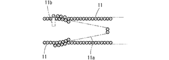
請求項3の補助治具は、密着コイルスプリングの一端が徐々に縮径しているので、他端に別の密着コイルスプリングの縮径部をねじ込むようにすれば、コイルの螺旋によって一方の密着コイルスプリングの縮径部側が他方の密着コイルスプリングの他端部の内側へスムーズにねじ込まれ、2つの密着コイルスプリングを容易に連結することができる。したがって、複数の密着コイルスプリングを容易しておけば、挿入するコルゲート管に適合した長さの補助治具を容易に形成することができる。また、縮径部を先頭にしてコルゲート管を挿入していくようにすれば、既設配管との摩擦抵抗をより少なくすることができる。 In the auxiliary jig according to the third aspect, since one end of the close contact coil spring is gradually reduced in diameter, if the reduced diameter portion of another close contact coil spring is screwed into the other end, one of the close contact is caused by the spiral of the coil. The reduced diameter side of the coil spring is smoothly screwed into the inside of the other end of the other contact coil spring, and the two contact coil springs can be easily connected. Therefore, if a plurality of contact coil springs are facilitated, an auxiliary jig having a length suitable for the corrugated pipe to be inserted can be easily formed. If the corrugated pipe is inserted with the reduced diameter portion at the head, the frictional resistance with the existing pipe can be further reduced.
請求項4の補助治具は、密着コイルスプリングの他端に半径方向内側に突出する係止突起を備えているので、密着コイルスプリングが、上記のように連結されたとき、係止突起が、内側に入り込んだ密着コイルスプリングのループとループとの間に入り込み、密着コイルスプリングの抜けを簡単かつ確実に防止できる。すなわち、配管長が長い場合や曲がりが多い場合など、コルゲート管との抵抗が大きくても、挿入後にスプリングを引き抜く際にスプリング同士がその接続部で外れるということがない。 The auxiliary jig according to claim 4 is provided with a locking projection protruding radially inward at the other end of the contact coil spring, so that when the contact coil spring is connected as described above, the locking projection is It is possible to easily and surely prevent the contact coil spring from slipping out by entering between the loops of the contact coil spring that has entered inside. That is, even when the resistance to the corrugated pipe is large, such as when the pipe length is long or when there are many bends, the springs do not come off at the connecting portion when the spring is pulled out after insertion.
請求項5の補助治具は、引っ張りに対して密着コイルスプリングより伸びが少ない線状材が、密着コイルスプリングの全長に渡って密着コイルスプリング内に配置されているとともに、線状材の一端が密着コイルスプリングに固着されているので、コルゲート管からのスプリングの引き抜き時にスプリングに過剰な引っ張り力を加えることなく、ワイヤロープを引っ張ってスプリングを引き抜くことができる。したがって、スプリングの寿命が長くなる。
In the auxiliary jig according to the fifth aspect, the linear material that is less stretched than the close coil spring with respect to the tension is disposed in the close coil spring over the entire length of the close coil spring, and one end of the linear material is Since it is fixed to the contact coil spring, the spring can be pulled out by pulling the wire rope without applying excessive pulling force to the spring when pulling out the spring from the corrugated tube. Therefore, the life of the spring is extended.
以下に、本発明を、その実施の形態をあらわす図面を参照しつつ詳しく説明する。
図1〜図6は、本発明の挿入補助治具の1つの実施の形態をあらわしている。
Hereinafter, the present invention will be described in detail with reference to the drawings showing embodiments thereof.
1 to 6 show one embodiment of the insertion assisting jig of the present invention.
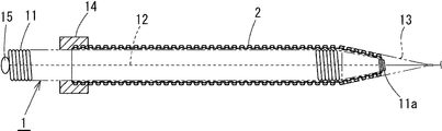
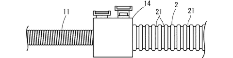
図1に示すように、この挿入補助治具1は、密着コイルスプリング11と、スプリング伸長防止用線状材としてのワイヤロープ12と、接続ネット13と、スプリング固定具14とを備えている。
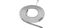
密着コイルスプリング11は、図1〜図3に示すように、一端が徐々に縮径する縮径部11aとなっていて、他端にスプリングを構成するワイヤの一端を折り曲げて形成した係止突起11bを備えている。
As shown in FIG. 1, the insertion assisting jig 1 includes a close-
As shown in FIGS. 1 to 3, the close
ワイヤロープ12は、図1および図4に示すように、密着コイルスプリング11の内部に縮径部11a側から係止突起11bが設けられた他端まで通されていて、他端でワイヤ固定治具15を介して密着コイルスプリング11に固定されている。
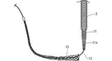
接続ネット13は、細いワイヤロープが円錐状に編まれて形成され、円錐の中心軸方向に伸長されると縮径して、コルゲート管2の周壁に密着してコルゲート管2の外壁をしっかりと把持するようになっていて、円錐の頂部で、ワイヤロープ12に固定されている。
As shown in FIGS. 1 and 4, the
The
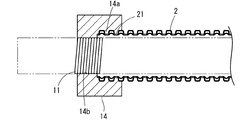
スプリング固定具14は、図示していないが、2つ割になるようになっていて、図5および図6に示すように、コルゲート管2の外壁部の溝21に嵌まり込むコルゲート管係止突条14aと、密着コイルスプリング11の外面が嵌まり込む螺旋溝14bが内面に設けられている。
Although not shown in the figure, the
つぎに、この挿入補助治具1を用いた本発明の挿入工法を詳しく説明する。
図示していないが、まず、先導糸の先端に落下傘状の風圧受け具を取り付け、風圧受け具を既設配管の一端に挿入したのち、コンプレッサ等で圧縮空気を既設配管の一端から他端に向けて送り、風圧受け具を圧縮空気によって既設配管の他端に送ることによって、先導糸を既設配管内に通す。
Next, the insertion method of the present invention using this insertion assisting jig 1 will be described in detail.
Although not shown, first attach a parachute-shaped wind pressure receiving device to the tip of the leading yarn, insert the wind pressure receiving device into one end of the existing piping, and then direct the compressed air from one end of the existing piping to the other end with a compressor or the like. The leading yarn is passed through the existing pipe by sending the wind pressure receiver to the other end of the existing pipe by compressed air.
そして、先導糸の一端に牽引用ワイヤロープを取り付け、先導糸の他端を引っ張り、既設配管に牽引用ワイヤロープを通す。
また、既設配管に通すコルゲート管2を用意し、挿入補助治具1の密着コイルスプリング11をコルゲート管2に挿通する。
Then, a pulling wire rope is attached to one end of the leading yarn, the other end of the leading yarn is pulled, and the pulling wire rope is passed through the existing pipe.
In addition, a
なお、1本の密着コイルスプリング11では、コルゲート管2より短い場合は、図3に示すように、別の密着コイルスプリング11を上述したように接続し、コルゲート管2より少し長くなるようにする。
In addition, when the single
続いて、コルゲート管2の牽引側の先端を、その軸方向に数箇所(好ましくは、90°ずつ計4箇所)切断し、切断部を密着コイルスプリング11の縮径部11aに沿わせた状態で接続ネット13をその上方から被せたのち、接続ネット13を伸長させて、コルゲート管2の上から把持する。
コルゲート管2の他端をスプリング固定具14を介して密着コイルスプリング11に固定するとともに、コルゲート管2の牽引側端部から出たワイヤロープ12の端部を牽引用ワイヤロープRの一端に固定する。
Subsequently, the tip on the pulling side of the
The other end of the
そして、図7に示すように、既設配管Pの一端から作業者Aがコルゲート管2を既設配管P内に送り込む動作をしたのち、既設配管Pの他端から作業者Bが牽引用ワイヤロープRを牽引する動作を行うという作業を繰り返し、コルゲート管2を既設配管Pに挿入する。
そして、既設配管Pの他端からコルゲート管2の先端部がある程度突出すれば、スプリング固定具14を取り外すとともに、接続ネット13による把持を解除したのち、ワイヤロープ12を持って、牽引側から密着コイルスプリング11を引っ張り、コルゲート管2の内部から引き出すようになっている。
Then, as shown in FIG. 7, after the worker A sends the
If the tip of the
(実施例1)
25A用のコルゲート管(内径φ18mm)に、外径16.0mm、ワイヤ径1.5mmの密着コイルスプリングを図1に示すように挿入し、スプリング固定具14を介して密着コイルスプリングをコルゲート管に固定するとともに、密着コイルスプリング内に中心ワイヤロープを挿通し、中心ワイヤロープの一端を密着コイルスプリングに固定した状態で、0.6mピッチで曲がり部を設けた呼び径25Aの配管中に、牽引動作と、押し込み動作とを繰り返し行い、コルゲート管を配管中に挿入し、曲がり通過数および挿入状態を調べた。
(Example 1)
A close-contact coil spring having an outer diameter of 16.0 mm and a wire diameter of 1.5 mm is inserted into a 25 A corrugated tube (inner diameter φ18 mm) as shown in FIG. 1, and the close-contact coil spring is inserted into the corrugated tube via a
(実施例2)
密着コイルスプリングとして外径17.5mmのものを用いた以外は、実施例1と同様にしてコルゲート管を配管中に挿入し、曲がり通過数および挿入状態を調べた。
(Example 2)
A corrugated tube was inserted into the pipe in the same manner as in Example 1 except that a close contact coil spring having an outer diameter of 17.5 mm was used, and the number of bent passages and the insertion state were examined.
(実施例3)
密着コイルスプリングとして外径14.0mmのものを用いた以外は、実施例1と同様にしてコルゲート管を配管中に挿入し、曲がり通過数および挿入状態を調べた。
(Example 3)
A corrugated tube was inserted into the pipe in the same manner as in Example 1 except that a close contact coil spring having an outer diameter of 14.0 mm was used, and the number of bent passages and the insertion state were examined.
(実施例4)
密着コイルスプリングとして外径14.0mmのものを用いるとともに、密着コイルスプリング内に中心ワイヤロープを挿通しなかった以外は、実施例1と同様にしてコルゲート管を配管中に挿入し、曲がり通過数および挿入状態を調べた。
Example 4
The corrugated tube was inserted into the pipe in the same manner as in Example 1 except that a close contact coil spring having an outer diameter of 14.0 mm was used and the central wire rope was not inserted into the close contact coil spring. And the insertion state was examined.
(実施例5)
密着コイルスプリングをコルゲート管に固定せず、密着コイルスプリング内に中心ワイヤロープを挿通しなかった以外は、実施例1と同様にしてコルゲート管を配管中に挿入し、曲がり通過数および挿入状態を調べた。
(Example 5)
The corrugated tube is inserted into the pipe in the same manner as in Example 1 except that the close coil spring is not fixed to the corrugated tube and the central wire rope is not inserted into the close coil spring. Examined.
(比較例1)
コルゲート管内に密着コイルスプリングを挿通しない状態で、コルゲート管を実施例1と同様にして配管中に挿入し、曲がり通過数および挿入状態を調べた。
上記実施例1〜5および比較例1で調べた曲がり通過数および挿入状態を、その実施条件と合わせて表1に示した。なお、表1中、固定は密着コイルスプリングとコルゲート管との固定をあらわす。
(Comparative Example 1)
The corrugated tube was inserted into the pipe in the same manner as in Example 1 with no tight coil spring inserted into the corrugated tube, and the number of bent passages and the inserted state were examined.
The number of bent passages and the insertion state examined in Examples 1 to 5 and Comparative Example 1 are shown in Table 1 together with the implementation conditions. In Table 1, “fixing” indicates fixing between the contact coil spring and the corrugated tube.

P 既設配管
R 牽引用ワイヤロープ(牽引用の線状材)
1 挿入補助治具
11 密着コイルスプリング
11a 縮径部
11b 係止突起
12 ワイヤロープ(スプリング伸長防止用線状材)
2 コルゲート管
13 接続ネット
14 スプリング固定具
15 ワイヤ固定治具
P Existing piping R Tow wire rope (wire material for towing)
DESCRIPTION OF SYMBOLS 1 Insertion
2
Claims (5)
Priority Applications (1)
| Application Number | Priority Date | Filing Date | Title |
|---|---|---|---|
| JP2004104022A JP2005291255A (en) | 2004-03-31 | 2004-03-31 | Method for inserting corrugated pipe into existing piping and insertion auxiliary jig used for this method |
Applications Claiming Priority (1)
| Application Number | Priority Date | Filing Date | Title |
|---|---|---|---|
| JP2004104022A JP2005291255A (en) | 2004-03-31 | 2004-03-31 | Method for inserting corrugated pipe into existing piping and insertion auxiliary jig used for this method |
Publications (1)
| Publication Number | Publication Date |
|---|---|
| JP2005291255A true JP2005291255A (en) | 2005-10-20 |
Family
ID=35324429
Family Applications (1)
| Application Number | Title | Priority Date | Filing Date |
|---|---|---|---|
| JP2004104022A Pending JP2005291255A (en) | 2004-03-31 | 2004-03-31 | Method for inserting corrugated pipe into existing piping and insertion auxiliary jig used for this method |
Country Status (1)
| Country | Link |
|---|---|
| JP (1) | JP2005291255A (en) |
Cited By (2)
| Publication number | Priority date | Publication date | Assignee | Title |
|---|---|---|---|---|
| JP2007032759A (en) * | 2005-07-28 | 2007-02-08 | Nagoya City | Drawing method for buried pipe and connecting device and drawing device for the drawing method |
| CN104014098A (en) * | 2014-03-24 | 2014-09-03 | 华金义 | Hard fire-fighting water pipe with transverse tooth lines on transverse and vertical triangular suspended and fixed out walls |
-
2004
- 2004-03-31 JP JP2004104022A patent/JP2005291255A/en active Pending
Cited By (2)
| Publication number | Priority date | Publication date | Assignee | Title |
|---|---|---|---|---|
| JP2007032759A (en) * | 2005-07-28 | 2007-02-08 | Nagoya City | Drawing method for buried pipe and connecting device and drawing device for the drawing method |
| CN104014098A (en) * | 2014-03-24 | 2014-09-03 | 华金义 | Hard fire-fighting water pipe with transverse tooth lines on transverse and vertical triangular suspended and fixed out walls |
Similar Documents
| Publication | Publication Date | Title |
|---|---|---|
| US5548898A (en) | Method for providing a flexible covering for a portion of a tapered coil spring | |
| JP4122058B2 (en) | Method and apparatus for attaching a tubular device to a flexible wall | |
| GB2122318A (en) | Grip for pulling fibre optic cable | |
| JP2005291255A (en) | Method for inserting corrugated pipe into existing piping and insertion auxiliary jig used for this method | |
| US6941787B2 (en) | Bending device for thin-walled metal pipes | |
| JP2010223253A (en) | Actuator | |
| JP4495996B2 (en) | Synthetic resin double-layer corrugated pipe and method for repairing the pipe through which this corrugated pipe is inserted into an aged existing pipe | |
| JP2001311480A (en) | Pull up jig for plastic pipe | |
| JP2001241590A (en) | Bag for water stop | |
| JP2005291257A (en) | Method of inserting corrugated pipe into existing pipe | |
| JP3894868B2 (en) | Cable wiring jig | |
| JP4406576B2 (en) | Method for inserting corrugated pipe into existing piping and insertion jig used for this method | |
| CN209871219U (en) | Nylon cable tie for fixing studs of pipeline harness | |
| JP7444650B2 (en) | band clamp | |
| CN111146754A (en) | Protective device, protective assembly and installation method of elongated flexible member | |
| JP2018168945A (en) | Attachment for tool insertion | |
| JP2636874B2 (en) | Pipe lining method | |
| JP2026000301A (en) | Wire-running tools and wire-running methods | |
| JPH11325317A (en) | Polyolefin-based liner pipe and its construction method | |
| JP2962991B2 (en) | Suspension holder for laying a suspension in a sewer | |
| JPS6218796Y2 (en) | ||
| SU1192009A1 (en) | Method of pulling wires in flexible hoses | |
| JP2002267057A (en) | Corrugate pipe | |
| JP2004290806A (en) | Pig for pipe lining | |
| CN121756060A (en) | A method for installing circlips in stainless steel corrugated sheathing pipes |
Legal Events
| Date | Code | Title | Description |
|---|---|---|---|
| A621 | Written request for application examination |
Free format text: JAPANESE INTERMEDIATE CODE: A621 Effective date: 20061115 |
|
| A977 | Report on retrieval |
Free format text: JAPANESE INTERMEDIATE CODE: A971007 Effective date: 20090806 |
|
| A131 | Notification of reasons for refusal |
Effective date: 20090811 Free format text: JAPANESE INTERMEDIATE CODE: A131 |
|
| A02 | Decision of refusal |
Free format text: JAPANESE INTERMEDIATE CODE: A02 Effective date: 20091208 |