JP2005291232A - Ball bearing for strut - Google Patents
Ball bearing for strut Download PDFInfo
- Publication number
- JP2005291232A JP2005291232A JP2004102938A JP2004102938A JP2005291232A JP 2005291232 A JP2005291232 A JP 2005291232A JP 2004102938 A JP2004102938 A JP 2004102938A JP 2004102938 A JP2004102938 A JP 2004102938A JP 2005291232 A JP2005291232 A JP 2005291232A
- Authority
- JP
- Japan
- Prior art keywords
- ball bearing
- strut
- race
- races
- annular
- Prior art date
- Legal status (The legal status is an assumption and is not a legal conclusion. Google has not performed a legal analysis and makes no representation as to the accuracy of the status listed.)
- Granted
Links
- 238000007789 sealing Methods 0.000 claims abstract description 38
- 239000012212 insulator Substances 0.000 claims description 17
- 230000013011 mating Effects 0.000 claims 1
- 230000002093 peripheral effect Effects 0.000 description 14
- 239000000725 suspension Substances 0.000 description 7
- 239000000428 dust Substances 0.000 description 5
- XLYOFNOQVPJJNP-UHFFFAOYSA-N water Substances O XLYOFNOQVPJJNP-UHFFFAOYSA-N 0.000 description 5
- 238000005452 bending Methods 0.000 description 4
- 229910000831 Steel Inorganic materials 0.000 description 2
- 239000000314 lubricant Substances 0.000 description 2
- 239000010959 steel Substances 0.000 description 2
- 239000006096 absorbing agent Substances 0.000 description 1
- 239000000853 adhesive Substances 0.000 description 1
- 230000001070 adhesive effect Effects 0.000 description 1
- 238000013459 approach Methods 0.000 description 1
- 230000006866 deterioration Effects 0.000 description 1
- 230000002708 enhancing effect Effects 0.000 description 1
- 239000004519 grease Substances 0.000 description 1
- 239000000463 material Substances 0.000 description 1
- 238000005096 rolling process Methods 0.000 description 1
- 230000035939 shock Effects 0.000 description 1
- 229920003002 synthetic resin Polymers 0.000 description 1
- 239000000057 synthetic resin Substances 0.000 description 1
- 238000004073 vulcanization Methods 0.000 description 1
Images
Classifications
-
- F—MECHANICAL ENGINEERING; LIGHTING; HEATING; WEAPONS; BLASTING
- F16—ENGINEERING ELEMENTS AND UNITS; GENERAL MEASURES FOR PRODUCING AND MAINTAINING EFFECTIVE FUNCTIONING OF MACHINES OR INSTALLATIONS; THERMAL INSULATION IN GENERAL
- F16C—SHAFTS; FLEXIBLE SHAFTS; ELEMENTS OR CRANKSHAFT MECHANISMS; ROTARY BODIES OTHER THAN GEARING ELEMENTS; BEARINGS
- F16C33/00—Parts of bearings; Special methods for making bearings or parts thereof
- F16C33/30—Parts of ball or roller bearings
- F16C33/58—Raceways; Race rings
- F16C33/588—Races of sheet metal
-
- F—MECHANICAL ENGINEERING; LIGHTING; HEATING; WEAPONS; BLASTING
- F16—ENGINEERING ELEMENTS AND UNITS; GENERAL MEASURES FOR PRODUCING AND MAINTAINING EFFECTIVE FUNCTIONING OF MACHINES OR INSTALLATIONS; THERMAL INSULATION IN GENERAL
- F16C—SHAFTS; FLEXIBLE SHAFTS; ELEMENTS OR CRANKSHAFT MECHANISMS; ROTARY BODIES OTHER THAN GEARING ELEMENTS; BEARINGS
- F16C19/00—Bearings with rolling contact, for exclusively rotary movement
- F16C19/02—Bearings with rolling contact, for exclusively rotary movement with bearing balls essentially of the same size in one or more circular rows
- F16C19/10—Bearings with rolling contact, for exclusively rotary movement with bearing balls essentially of the same size in one or more circular rows for axial load mainly
-
- F—MECHANICAL ENGINEERING; LIGHTING; HEATING; WEAPONS; BLASTING
- F16—ENGINEERING ELEMENTS AND UNITS; GENERAL MEASURES FOR PRODUCING AND MAINTAINING EFFECTIVE FUNCTIONING OF MACHINES OR INSTALLATIONS; THERMAL INSULATION IN GENERAL
- F16C—SHAFTS; FLEXIBLE SHAFTS; ELEMENTS OR CRANKSHAFT MECHANISMS; ROTARY BODIES OTHER THAN GEARING ELEMENTS; BEARINGS
- F16C2326/00—Articles relating to transporting
- F16C2326/01—Parts of vehicles in general
- F16C2326/05—Vehicle suspensions, e.g. bearings, pivots or connecting rods used therein
Landscapes
- Engineering & Computer Science (AREA)
- General Engineering & Computer Science (AREA)
- Mechanical Engineering (AREA)
- Rolling Contact Bearings (AREA)
- Vehicle Body Suspensions (AREA)
- Fluid-Damping Devices (AREA)
Abstract
Description
本発明は、例えば車両のストラット式サスペンションに用いるストラット用玉軸受に関する。 The present invention relates to a ball bearing for struts used for, for example, a strut suspension of a vehicle.
ストラット式サスペンションは、ショックアブソーバーの周囲にコイルスプリングが装着されたもので、上部がストラットインシュレータを介して車体(ボディ)に支持され、下部がロアアームで支持される。このようなサスペンション用としての玉軸受(ストラット用玉軸受)は、ストラットインシュレータと、コイルスプリングの上端を受けるスプリングアッパシートとの間に組み込まれる。このストラット用玉軸受は、薄肉鋼板をプレス成形してなる二つのレース間に複数個の玉を介装し、両レースの径方向内外の端部を、互いに微小隙間を介して対向するように屈曲し、これら両レースの端部に相手側に接触するシールリップを設けて、その密封性を確保している(例えば特許文献1参照)。 The strut suspension has a coil spring mounted around a shock absorber, and an upper part is supported by a vehicle body (body) via a strut insulator and a lower part is supported by a lower arm. Such a ball bearing for suspension (ball bearing for struts) is incorporated between a strut insulator and a spring upper seat that receives the upper end of a coil spring. In this strut ball bearing, a plurality of balls are interposed between two races formed by press-forming a thin steel plate so that the inner and outer ends of both races face each other with a minute gap therebetween. A sealing lip that bends and contacts the other side is provided at the ends of both races to ensure the sealing performance (see, for example, Patent Document 1).
しかしながら、ストラット用玉軸受の外径側から泥水や粉塵などが直接的にかかることがあって、ストラット用玉軸受内部に泥水や粉塵が侵入する可能性が高く、そのため、当該軸受の寿命を延ばすためにその密封性をより向上させることが要求されてきている。
そこで、本発明は、ストラット式サスペンションに用いるストラット用玉軸受において、部品点数を増やすことなく、所定の密封性を確保できるようにしたものである。 In view of the above, the present invention provides a strut ball bearing for use in a strut type suspension that can ensure a predetermined sealing performance without increasing the number of components.
本発明第1によるストラット用玉軸受は、軸方向に対向する二つの環状のレース間に複数個の玉を転動自在に介装したストラット用玉軸受であって、一方のレースに、上記他方のレースを受ける環状受け部材側に延びかつ環状受け部材との間で非接触密封部を作る延長部を設けたことを特徴とするものである。 The strut ball bearing according to the first aspect of the present invention is a strut ball bearing in which a plurality of balls are rotatably mounted between two annular races facing each other in the axial direction. An extension portion is provided that extends toward the annular receiving member that receives the race and creates a non-contact sealing portion with the annular receiving member.
この場合、ストラット用玉軸受の構成部品を利用して非接触密封部を作っており、余分な部品を必要としない。また、非接触密封部によって軸受内部への泥水や粉塵などの侵入を抑制または防止する。 In this case, the non-contact sealing portion is made by using the components of the strut ball bearing, and no extra parts are required. In addition, the non-contact sealing portion suppresses or prevents the intrusion of muddy water and dust into the bearing.
好ましくは、上記非接触密封部が、上記一方のレースの延長部と環状受け部材との対向すきまによるラビリンスシールで構成される。また、好ましくは、上記両レースの内外径側に、互いの相手となるレースに接触して接触密封部を作るシールリップを設けることができる。このように非接触密封部に加えて、接触密封部を形成した多段の密封構造とすれば、密封性能の向上に貢献できる。 Preferably, the non-contact sealing portion is constituted by a labyrinth seal formed by a facing clearance between the extension portion of the one race and the annular receiving member. Preferably, a seal lip that makes contact with each other's races to form a contact sealing portion can be provided on the inner and outer diameter sides of the both races. Thus, if it is set as the multistage sealing structure which formed the contact sealing part in addition to the non-contact sealing part, it can contribute to the improvement of sealing performance.
本発明第2のストラット用玉軸受は、ストラットインシュレータとスプリングアッパシートとの外径側対向間に配置されるストラット用玉軸受であって、ストラットインシュレータ側に配置される環状の第1レースと、スプリングアッパシート側に配置される環状の第2レースと、上記両レース間に転動自在に介装される複数個の玉とを備え、上記第1レースの外径側を、ストラットインシュレータとスプリングアッパシートとの外径側の対向すきまを介して当該すきまの外側にまで延長し、その延長部を、スプリングアッパシートとの対向すきまによりラビリンスシール構造の非接触密封部を構成するものとしたことを特徴とするものである。 The second strut ball bearing of the present invention is a strut ball bearing disposed between the strut insulator and the spring upper seat facing the outer diameter side, and an annular first race disposed on the strut insulator side; An annular second race disposed on the spring upper seat side, and a plurality of balls interposed between the races so as to be freely rollable. A strut insulator and a spring are provided on the outer diameter side of the first race. Extending to the outside of the clearance through the clearance facing the outer sheet on the outer diameter side, and the extended portion shall constitute a non-contact sealing portion of the labyrinth seal structure with the clearance facing the spring upper seat It is characterized by.
この場合、ストラット用玉軸受の構成部品を利用して非接触密封部を作っており、余分な部品を必要としない。また、非接触密封部によって、泥水や粉塵などが、当該軸受内部に侵入してくる可能性を低減する。しかも、第1レースとスプリングアッパシートとの相対位置が設計上特定されるものであるから、第1レースとスプリングアッパシートとの間の対向すきまの管理が容易かつ高精度に行うことが可能で、非接触密封部による密封性を高める上でも、より効果的となる。 In this case, the non-contact sealing portion is made by using the components of the strut ball bearing, and no extra parts are required. Further, the non-contact sealing portion reduces the possibility that muddy water, dust or the like enters the bearing. Moreover, since the relative position between the first race and the spring upper seat is specified by design, the facing clearance between the first race and the spring upper seat can be easily and accurately controlled. Also, it is more effective in enhancing the sealing performance by the non-contact sealing portion.
好ましくは、上記両レースの内外径側に、互いの相手となるレースに接触して接触密封部を作るシールリップを設けることができる。このように非接触密封部に加えて、接触密封部を形成した多段の密封構造とすれば、密封性能の向上に貢献できる。 Preferably, a sealing lip that makes contact sealing portions by contacting the races that are the other party can be provided on the inner and outer diameter sides of the both races. Thus, if it is set as the multistage sealing structure which formed the contact sealing part in addition to the non-contact sealing part, it can contribute to the improvement of sealing performance.
本発明によれば、部品点数を増やすことなく、所定の密封性を確保できる。 According to the present invention, it is possible to ensure a predetermined sealing performance without increasing the number of parts.
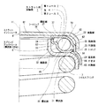
以下、本発明の最良の形態を図面を参照して説明する。図1は、ストラット用玉軸受(以下、単に玉軸受という)の片半分を示す断面図である。なお、ストラット式サスペンションの基本的な一般構成は周知であるから、図1では、本発明に関わるストラット式サスペンションの要部の構成のみを示している。 The best mode of the present invention will be described below with reference to the drawings. FIG. 1 is a cross-sectional view showing a half of a strut ball bearing (hereinafter simply referred to as a ball bearing). Since the basic general configuration of the strut suspension is well known, FIG. 1 shows only the configuration of the main part of the strut suspension according to the present invention.
同図に示す玉軸受1は、軸方向に対向配置される環状の第1レース2および第2レース3と、両レース2,3間に転動自在に介装された複数個の玉4とを備える。第1、第2レース2,3は、共に、例えばJIS規格のSPCCやSCM等で代表される薄肉鋼板をプレス加工することにより製作される。 A ball bearing 1 shown in FIG. 1 includes an annular first race 2 and second race 3 that are arranged opposite to each other in the axial direction, and a plurality of balls 4 that are rotatably interposed between both races 2 and 3. Is provided. Both the first and second races 2 and 3 are manufactured by pressing a thin steel plate represented by, for example, JIS standard SPCC or SCM.
第1レース2は、回転軸線11に対して径方向外方に延びる環状部21と、該環状部21の外径側から、玉4の軌道面として所定の曲率で軸方向一方(図1の下方)に向けて湾曲する湾曲部22と、湾曲部22からさらに軸方向一方に延びる円筒部23と、円筒部23からさらに拡径しながら軸方向一方に延びる延長部(湾曲部)24とを備える。
The first race 2 has an annular portion 21 extending radially outward with respect to the
第2レース3は、第1レース2の環状部21よりも若干径方向外方にずれた位置から径方向に延びる環状部31と、該環状部31の内径側に、玉4の軌道面として所定の曲率で軸方向他方(図1の上方)に向けて湾曲する湾曲部32と、湾曲部32からさらに径方向内向きに短く延びる環状部33と、環状部33からさらに軸方向他方に短く延びる円筒部34と、環状部31の外径端に、軸方向他方に向けて僅かに屈曲する屈曲部35とを備える。
The second race 3 has an annular portion 31 extending in a radial direction from a position slightly shifted outward in the radial direction from the annular portion 21 of the first race 2, and a raceway surface of the ball 4 on the inner diameter side of the annular portion 31. A curved portion 32 that curves toward the other axial direction (upward in FIG. 1) with a predetermined curvature, an annular portion 33 that extends further inward in the radial direction from the curved portion 32, and a shorter axially other portion from the annular portion 33. A
玉4は、第1レース2の湾曲部22の内周面と、第2レース3の湾曲部32の外周面とをそれぞれ軌道面とし、第1レース2と第2レース3とに対し斜めに接触する状態になっている。具体的に、玉4の作用線10は、図1に対して、第1レース2を上側に、第2レース3を下側に配置した状態で、上から下へ向かうに従い回転軸線11に近づくように傾いている。
The ball 4 has an inner circumferential surface of the curved portion 22 of the first race 2 and an outer circumferential surface of the curved portion 32 of the second race 3, respectively, and is inclined with respect to the first race 2 and the second race 3. You are in contact. Specifically, the
そして、第1レース2の円筒部23の内周面を第2レース3の屈曲部35の外周面に微小なすきまを介して径方向で対向させるとともに、当該延長部24の内周面に、第2レース3の屈曲部35の外周面に接触するラジアルシールリップ25を被着している。第1レース2の環状部21の径方向内側の内周面と、第2レース3の円筒部34の軸方向他方側端面とを微小なすきまを介して軸方向で対向させたうえで、第2レース3の円筒部34の軸方向他方側端面に、第1レース2の環状部21の内周面に接触する二つのアキシアルシールリップ36,37を被着している。これらシールリップ25,36,37により玉4の配置空間である両レース2,3内部を外部から密封し、この密封空間内に図示しないグリース等の潤滑剤を封入している。ラジアルシールリップ25の内径寸法は第2レース3の環状部31の外径寸法よりも小さくなっており、これによって両レース2,3は非分離となっている。シールリップ25,36,37は、例えばゴムや合成樹脂等の公知の材料で構成されており、それぞれ両レース2,3に加硫接着あるいは適宜の接着剤にて被着されている。
Then, the inner peripheral surface of the cylindrical portion 23 of the first race 2 is opposed to the outer peripheral surface of the bent portion 35 of the second race 3 in the radial direction through a minute gap, and the inner peripheral surface of the extension portion 24 is A radial seal lip 25 that contacts the outer peripheral surface of the bent portion 35 of the second race 3 is attached. The inner peripheral surface on the radially inner side of the annular portion 21 of the first race 2 and the other end surface in the axial direction of the
以上の構成を備えた玉軸受1は、第1レース2を上側に、第2レース3を下側に配置した状態で、ストラットインシュレータ6とコイルスプリング7の上端を受けるスプリングアッパシート8との間に配置される。ストラットインシュレータ6やスプリングアッパシート8が環状受け部材の一例である。
The ball bearing 1 having the above-described configuration is provided between the
ストラットインシュレータ6は、径方向に延びる環状部61と、該環状部61の外径側から軸方向下向きに延びる外筒部62とを備え、環状部61と外筒部62との間に湾曲部63が形成されている。そして、第1レース2の環状部21とストラットインシュレータ6の環状部61とが当接し、第1レース2の円筒部23とストラットインシュレータ6の外筒部62とが当接し、第1レース2の湾曲部22とストラットインシュレータ6の湾曲部63との間にすきまが形成されている。
The
スプリングアッパシート8は、径方向に延びる環状部81と、該環状部81の内径側から軸方向上向きに延びる内筒部82と、環状部81の外径側からストラットインシュレータ6の外筒部62の内周端と軸方向に略一致する位置で軸方向下向きに延びる外筒部83とを備えるとともに、環状部81と外筒部83との間に湾曲コーナー部84が、環状部81と内筒部82との間に湾曲部85が形成されている。スプリングアッパシート8の環状部81の内周面と外筒部83の内周面とにコイルスプリング7の上端部分が当接されている。この場合、湾曲コーナー部84の内周面とコイルスプリング7の上端部分との間に若干のすきまが存在する。そして、第2レース3の円筒部34とスプリングアッパシート8の内筒部82とが当接し、第2レース3の環状部31とスプリングアッパシート8の環状部81とが当接し、第2レース3の湾曲部32とスプリングアッパシート8の湾曲部85との間にすきまが形成されている。
The spring
以上の構成において、第1レース2の延長部24は、ストラットインシュレータ6の外径側である外筒部62の内周縁とスプリングアッパシート8の外径側である湾曲コーナー部84との対向すきまから外部に延長され、その湾曲コーナー部84から外筒部83の端縁側にいたる領域の外周面に、微小なすきま86を介して略平行に対向している。このすきま86は、ラビリンスシール(非接触密封部)となっている。この結果、上記構成では、部品点数を増やすこともなく、玉軸受1の外径側に上記ラジアルシールリップ25による接触密封部に加えて、すきま86による非接触密封部とで多段の密封構造が形成されることとなり、泥水や粉塵などに対する密封性がきわめて高くなっている。したがって、玉軸受1の内部に封入される潤滑剤の劣化を長期にわたって防止できると共に、転がり特性ならびに寿命が向上し、ストラット式サスペンションの玉軸受としてその信頼性の向上に大きく貢献できる。
(他の形態)
図2を参照して、本発明の他の形態を説明すると、コイルスプリング7の上端部分の外径寸法が大きい場合には、スプリングアッパシート8の環状部81を径方向外向きに延ばすように大径化する必要がある。この場合、ストラットインシュレータ6の外筒部62の内周端よりもスプリングアッパシート8の環状部81が径方向外方に延びている。この形態では、スプリングアッパシート8の環状部81の外周面にあわせて、第1レース2の延長部24を径方向外向きに延ばした形状とし、スプリングアッパシート8の環状部81の外周面に軸方向に微小なすきま87を介して略平行に対向させることができる。この場合も、接触密封部であるラジアルシールリップ25に加えて、さらに外径側にすきま87によるラビリンスシール(非接触密封部)が形成されるから、図1の形態と同様にその密封性をきわめて高くすることができる。
In the above configuration, the extension portion 24 of the first race 2 is a gap between the inner peripheral edge of the outer
(Other forms)
With reference to FIG. 2, another embodiment of the present invention will be described. When the outer diameter of the upper end portion of the
上記各形態の玉軸受1は、アンギュラタイプだけでなく、作用線を径方向に沿わせるラジアルタイプや、軸方向に沿わせるスラストタイプにも適用できる。
The
なお、図1や図2に示す実施の形態において、シールリップ25,36,37を無くした構成や、シールリップ25またはシールリップ36,37のいずれか一方を無くした構成も本発明に含まれる。
In the embodiment shown in FIGS. 1 and 2, the present invention includes a configuration in which the
1…玉軸受、2…第1レース、3…第2レース、4…玉、24…第1レースの延長部、25…シールリップ、8…スプリングアッパシート、83…外筒部。
DESCRIPTION OF
Claims (5)
一方のレースに、上記他方のレースを受ける環状受け部材側に延びかつ環状受け部材との間で非接触密封部を作る延長部を設けたことを特徴とするストラット用玉軸受。 A ball bearing for struts in which a plurality of balls are rotatably mounted between two annular races facing each other in the axial direction,
A strut ball bearing, wherein one of the races is provided with an extension that extends toward the annular receiving member that receives the other race and that forms a non-contact sealing portion with the annular receiving member.
ストラットインシュレータ側に配置される環状の第1レースと、
スプリングアッパシート側に配置される環状の第2レースと、
上記両レース間に転動自在に介装される複数個の玉とを備え、
上記第1レースの外径側を、ストラットインシュレータとスプリングアッパシートとの外径側の対向すきまを介して当該すきまの外側にまで延長し、その延長部を、スプリングアッパシートとの対向すきまによりラビリンスシール構造の非接触密封部を構成するものとした、ことを特徴とするストラット用玉軸受。 A strut ball bearing disposed between the strut insulator and the spring upper seat facing the outer diameter side,
An annular first race disposed on the strut insulator side;
An annular second race disposed on the spring upper seat side;
A plurality of balls interposed between the races so as to roll freely,
The outer diameter side of the first race is extended to the outside of the clearance through the opposing clearance on the outer diameter side of the strut insulator and the spring upper seat, and the extension portion is extended to the labyrinth by the opposing clearance with the spring upper seat. A strut ball bearing characterized in that it constitutes a non-contact sealing portion of a seal structure.
Priority Applications (1)
| Application Number | Priority Date | Filing Date | Title |
|---|---|---|---|
| JP2004102938A JP4385823B2 (en) | 2004-03-31 | 2004-03-31 | Strut ball bearing |
Applications Claiming Priority (1)
| Application Number | Priority Date | Filing Date | Title |
|---|---|---|---|
| JP2004102938A JP4385823B2 (en) | 2004-03-31 | 2004-03-31 | Strut ball bearing |
Publications (2)
| Publication Number | Publication Date |
|---|---|
| JP2005291232A true JP2005291232A (en) | 2005-10-20 |
| JP4385823B2 JP4385823B2 (en) | 2009-12-16 |
Family
ID=35324411
Family Applications (1)
| Application Number | Title | Priority Date | Filing Date |
|---|---|---|---|
| JP2004102938A Expired - Lifetime JP4385823B2 (en) | 2004-03-31 | 2004-03-31 | Strut ball bearing |
Country Status (1)
| Country | Link |
|---|---|
| JP (1) | JP4385823B2 (en) |
Cited By (5)
| Publication number | Priority date | Publication date | Assignee | Title |
|---|---|---|---|---|
| JP2008151256A (en) * | 2006-12-18 | 2008-07-03 | Jtekt Corp | Sealed thrust ball bearing |
| WO2009122746A1 (en) * | 2008-04-02 | 2009-10-08 | オイレス工業株式会社 | Thrust slide bearing |
| WO2009128252A1 (en) * | 2008-04-18 | 2009-10-22 | オイレス工業株式会社 | Thrust slide bearing |
| DE102008029018A1 (en) | 2008-06-18 | 2009-12-24 | Schaeffler Kg | Spring strut bearing, has bearing disk with flange that is formed with deformation degree which is greater than deformation degree of bearing disk, where deformation degree amounts to thirty percentage |
| JP2013015226A (en) * | 2012-10-22 | 2013-01-24 | Oiles Corp | Thrust sliding bearing |
-
2004
- 2004-03-31 JP JP2004102938A patent/JP4385823B2/en not_active Expired - Lifetime
Cited By (10)
| Publication number | Priority date | Publication date | Assignee | Title |
|---|---|---|---|---|
| JP2008151256A (en) * | 2006-12-18 | 2008-07-03 | Jtekt Corp | Sealed thrust ball bearing |
| WO2009122746A1 (en) * | 2008-04-02 | 2009-10-08 | オイレス工業株式会社 | Thrust slide bearing |
| KR101266551B1 (en) | 2008-04-02 | 2013-05-24 | 오일레스고교 가부시키가이샤 | Thrust slide bearing |
| US9624969B2 (en) | 2008-04-02 | 2017-04-18 | Oiles Corporation | Thrust sliding bearing |
| US10006485B2 (en) | 2008-04-02 | 2018-06-26 | Oiles Corporation | Thrust sliding bearing |
| WO2009128252A1 (en) * | 2008-04-18 | 2009-10-22 | オイレス工業株式会社 | Thrust slide bearing |
| JP2009257516A (en) * | 2008-04-18 | 2009-11-05 | Oiles Ind Co Ltd | Thrust sliding bearing |
| DE102008029018A1 (en) | 2008-06-18 | 2009-12-24 | Schaeffler Kg | Spring strut bearing, has bearing disk with flange that is formed with deformation degree which is greater than deformation degree of bearing disk, where deformation degree amounts to thirty percentage |
| DE102008029018B4 (en) | 2008-06-18 | 2022-05-12 | Schaeffler Technologies AG & Co. KG | strut bearing |
| JP2013015226A (en) * | 2012-10-22 | 2013-01-24 | Oiles Corp | Thrust sliding bearing |
Also Published As
| Publication number | Publication date |
|---|---|
| JP4385823B2 (en) | 2009-12-16 |
Similar Documents
| Publication | Publication Date | Title |
|---|---|---|
| CN103547822B (en) | Thrust plain bearings made of synthetic resin | |
| CN101855464B (en) | Bearing sealing device and wheel bearing using the same | |
| JP4434768B2 (en) | Suspension thrust bearing device | |
| CN102822542A (en) | Axial thrust bearing device with a mobile sealing ring | |
| JP4997822B2 (en) | Plain bearing | |
| JP2021143734A (en) | Strut bearing and vehicular strut type suspension | |
| JP2006513374A (en) | Plastic ring bearings especially for use in McPherson struts | |
| CN105864282A (en) | Rolling bearing comprising sealing flange | |
| JP4385823B2 (en) | Strut ball bearing | |
| JP2010071323A (en) | Sealing device | |
| JP5328136B2 (en) | Wheel bearing | |
| JP2022033225A (en) | Sealing device | |
| CN106122263B (en) | Bearings including elastomeric bearing flanges | |
| JP7417370B2 (en) | Bearing device for wheels | |
| US6786644B2 (en) | Sealing device for rolling bearings | |
| JP2010151249A (en) | Bearing for strut | |
| KR102512689B1 (en) | Rolling bearing comprising a sealing flange | |
| JP2013060975A (en) | Sealing device and roller bearing device | |
| JP2006322505A (en) | Thrust bearing | |
| JP4417190B2 (en) | Sealing device | |
| KR102901361B1 (en) | Vehicle wheel bearing having reduced drag torque and improved sealing function | |
| JP2008230279A (en) | Strut bearing | |
| JP2006322509A (en) | Thrust bearing | |
| JP2005233304A (en) | Ball bearing for strut | |
| JP2006002815A (en) | Bearing unit for rolling stock |
Legal Events
| Date | Code | Title | Description |
|---|---|---|---|
| A621 | Written request for application examination |
Free format text: JAPANESE INTERMEDIATE CODE: A621 Effective date: 20070307 |
|
| A977 | Report on retrieval |
Free format text: JAPANESE INTERMEDIATE CODE: A971007 Effective date: 20090319 |
|
| A131 | Notification of reasons for refusal |
Free format text: JAPANESE INTERMEDIATE CODE: A131 Effective date: 20090324 |
|
| A521 | Written amendment |
Free format text: JAPANESE INTERMEDIATE CODE: A523 Effective date: 20090525 |
|
| TRDD | Decision of grant or rejection written | ||
| A01 | Written decision to grant a patent or to grant a registration (utility model) |
Free format text: JAPANESE INTERMEDIATE CODE: A01 Effective date: 20090908 |
|
| A01 | Written decision to grant a patent or to grant a registration (utility model) |
Free format text: JAPANESE INTERMEDIATE CODE: A01 |
|
| A61 | First payment of annual fees (during grant procedure) |
Free format text: JAPANESE INTERMEDIATE CODE: A61 Effective date: 20090921 |
|
| R150 | Certificate of patent or registration of utility model |
Free format text: JAPANESE INTERMEDIATE CODE: R150 |
|
| FPAY | Renewal fee payment (event date is renewal date of database) |
Free format text: PAYMENT UNTIL: 20121009 Year of fee payment: 3 |