JP2005291160A - Compressor - Google Patents

Compressor Download PDF

Info

Publication number
JP2005291160A
JP2005291160A JP2004110195A JP2004110195A JP2005291160A JP 2005291160 A JP2005291160 A JP 2005291160A JP 2004110195 A JP2004110195 A JP 2004110195A JP 2004110195 A JP2004110195 A JP 2004110195A JP 2005291160 A JP2005291160 A JP 2005291160A
Authority
JP
Japan
Prior art keywords
compressor
chamber
refrigerant gas
suction
housing
Prior art date
Legal status (The legal status is an assumption and is not a legal conclusion. Google has not performed a legal analysis and makes no representation as to the accuracy of the status listed.)
Pending
Application number
JP2004110195A
Other languages
Japanese (ja)
Inventor
Fuminobu Enoshima
史修 榎島
Tetsuhiko Fukanuma
哲彦 深沼
Masaki Ota
太田  雅樹
Kyoichi Kinoshita
恭一 木下
Katsuaki Tanaka
勝章 田中
Motoharu Tanizawa
元治 谷澤
Current Assignee (The listed assignees may be inaccurate. Google has not performed a legal analysis and makes no representation or warranty as to the accuracy of the list.)
Toyota Industries Corp
Original Assignee
Toyota Industries Corp
Priority date (The priority date is an assumption and is not a legal conclusion. Google has not performed a legal analysis and makes no representation as to the accuracy of the date listed.)
Filing date
Publication date
Application filed by Toyota Industries Corp filed Critical Toyota Industries Corp
Priority to JP2004110195A priority Critical patent/JP2005291160A/en
Publication of JP2005291160A publication Critical patent/JP2005291160A/en
Pending legal-status Critical Current

Links

Images

Landscapes

  • Compressor (AREA)
  • Compressors, Vaccum Pumps And Other Relevant Systems (AREA)

Abstract

<P>PROBLEM TO BE SOLVED: To provide a compressor capable of improving compression efficiency by restricting temperature rise of intake cooling medium gas without providing new members or remodeling structure. <P>SOLUTION: A rear housing 14 provided with an intake chamber 24 and a discharge chamber 25 is jointed to an end surface of a cylinder block 11 through a valve/port forming member 13. The cylinder block 11 and a rear housing 14 are formed of aluminum alloy for achieving light weight. In the rear housing 1, a porous thermal spraying layer 37 is formed in wall surfaces of the intake chamber 24 and the discharge chamber 25. The thermal spraying layer 37 is formed of metal of lower heat conductivity than material composing the walls of the rear block 14. The thermal spraying layer 37 is formed of nickel, it is, for example, 150-200 μm thick, and its porosity is 5% or more. <P>COPYRIGHT: (C)2006,JPO&NCIPI

Description

本発明は圧縮機に関する。   The present invention relates to a compressor.

ピストン式圧縮機においては、シリンダブロックに形成されたシリンダボア内にピストンが収容され、吸入室及び吐出室を区画形成するハウジングが、吸入孔及び吐出孔が形成されたバルブプレートを介して、シリンダブロックの端面に対し接合されている。そして、回転軸の回転が駆動機構を介してピストンの往復運動に変換され、ピストンの往復運動により吸入室内の冷媒ガスを吸入孔を通してシリンダボア内の圧縮室に吸入し、圧縮された冷媒ガスを吐出孔を通して吐出室へ吐出するように構成されている。   In a piston type compressor, a piston is housed in a cylinder bore formed in a cylinder block, and a housing that partitions and forms a suction chamber and a discharge chamber is connected to the cylinder block via a valve plate in which a suction hole and a discharge hole are formed. It is joined to the end face of Then, the rotation of the rotating shaft is converted into the reciprocating motion of the piston through the drive mechanism, and the reciprocating motion of the piston sucks the refrigerant gas in the suction chamber through the suction hole into the compression chamber in the cylinder bore, and discharges the compressed refrigerant gas. It is comprised so that it may discharge to a discharge chamber through a hole.

ハウジングに設けられた吐出室は、圧縮された冷媒ガス(吐出ガス)により高温に加熱されている。そのため、外部冷媒回路から吸入室へ流入した低温の冷媒ガスが、吐出室と吸入室とを区画するハウジングの壁面やバルブプレートを介して伝達される熱により加熱される。そして、吸入室内の冷媒ガスがシリンダボア内の圧縮室へ吸入される以前に加熱されて膨張する状態となり、圧縮室への実質的な冷媒ガスの吸入量が減少し、体積効率が低下するという問題がある。また、吸入冷媒ガスが加熱された場合には、圧縮室で圧縮された圧縮ガスの温度も上昇し、このため吐出冷媒ガスの温度が上昇して、圧縮機や冷房回路のシール部材等の熱による劣化が生じ易いという問題があった。   The discharge chamber provided in the housing is heated to a high temperature by the compressed refrigerant gas (discharge gas). Therefore, the low-temperature refrigerant gas flowing into the suction chamber from the external refrigerant circuit is heated by the heat transmitted through the wall surface of the housing and the valve plate that partition the discharge chamber and the suction chamber. Then, the refrigerant gas in the suction chamber is heated and expanded before being sucked into the compression chamber in the cylinder bore, so that the substantial amount of refrigerant gas sucked into the compression chamber is reduced and the volume efficiency is lowered. There is. In addition, when the intake refrigerant gas is heated, the temperature of the compressed gas compressed in the compression chamber also rises. For this reason, the temperature of the discharged refrigerant gas rises, and heat from the compressor, the seal member of the cooling circuit, etc. There has been a problem that deterioration due to is likely to occur.

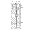
この問題を解決する手段として、吸入室及び吐出室の区画壁に断熱手段を設けたピストン式圧縮機が提案されている(例えば、特許文献1参照。)。特許文献1に開示された圧縮機は、図6に示すように、吸入室51及び吐出室52を備えたハウジング53が、シリンダブロック54の端面に対し、吸入孔55及び吐出孔56が形成されたバルブプレート57を介して接合されている。吸入室51及び吐出室52は区画壁58により区画され、区画壁58には断熱手段としての断熱溝58aが設けられている。特許文献1には、断熱手段としての断熱溝58aを設ける代わりに、吐出室の内壁を覆うように断熱手段としての樹脂等の断熱シートを形成することや、区画壁58の外周に断熱手段としての断熱リングを形成することも開示されている。   As means for solving this problem, a piston type compressor in which heat insulating means is provided on the partition walls of the suction chamber and the discharge chamber has been proposed (see, for example, Patent Document 1). As shown in FIG. 6, in the compressor disclosed in Patent Document 1, a housing 53 including a suction chamber 51 and a discharge chamber 52 is formed with a suction hole 55 and a discharge hole 56 on the end surface of the cylinder block 54. Are joined via a valve plate 57. The suction chamber 51 and the discharge chamber 52 are partitioned by a partition wall 58, and the partition wall 58 is provided with a heat insulating groove 58a as heat insulating means. In Patent Document 1, instead of providing a heat insulating groove 58a as a heat insulating means, a heat insulating sheet such as a resin as a heat insulating means is formed so as to cover the inner wall of the discharge chamber, or as a heat insulating means on the outer periphery of the partition wall 58. Is also disclosed.

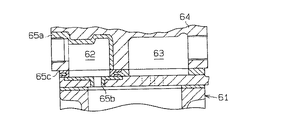
また、図7に示すように、シリンダ61の端部に、吸入室(吸込室)62と吐出室63とが形成されたシリンダヘッド64を設けた圧縮機において、シリンダヘッド64を放熱性の良い材料で製造し、かつ、シリンダヘッド64の吸入室62を断熱部材65a,65b,65cにより形成したものも提案されている(例えば、特許文献2参照。)。   Further, as shown in FIG. 7, in a compressor provided with a cylinder head 64 in which a suction chamber (suction chamber) 62 and a discharge chamber 63 are formed at the end of the cylinder 61, the cylinder head 64 has good heat dissipation. A material made of a material and having the suction chamber 62 of the cylinder head 64 formed of heat insulating members 65a, 65b, 65c has also been proposed (see, for example, Patent Document 2).

また、高温で使用する部材、例えば、ガスタービンの動・静翼においては、母材金属を高温の燃焼ガスから守るために、ボンドコーティングを行い、さらにその上にセラミックスによる遮熱コーティングが行われていることが開示されている。そして、遮熱特性を向上させるため又は部材の長寿命化を図るために、溶射により多孔質のセラミックスコーティングを施す試みがなされていることも開示されている(例えば、特許文献3参照。)。そして、特許文献3には、空孔率や空孔の大きさを制御できる多孔質溶射皮膜として、セラミックスをコーティングしてなる炭素粉末を溶射して形成された溶射皮膜中の炭素を燃焼させて空孔を形成させてなる多孔質溶射皮膜及びその製造方法が開示されている。
特開平5−164042号公報(明細書の段落[0006]、[0012]、図1) 実開平2−31382号公報 特開平9−263955号公報(明細書の段落[0002]、[0011])
In addition, for members used at high temperatures, for example, moving and stationary blades of gas turbines, bond coating is applied to protect the base metal from high-temperature combustion gas, and thermal barrier coating with ceramics is further applied thereon. It is disclosed. It is also disclosed that an attempt has been made to apply a porous ceramic coating by thermal spraying in order to improve the heat shielding characteristics or to extend the life of the member (see, for example, Patent Document 3). And in patent document 3, carbon in the sprayed coating formed by spraying the carbon powder formed by coating ceramics as a porous sprayed coating capable of controlling the porosity and the size of the pores is burned. A porous sprayed coating formed with pores and a method for producing the same are disclosed.
JP-A-5-164042 (paragraphs [0006] and [0012] in FIG. 1, FIG. 1) Japanese Utility Model Publication No. 2-331382 JP-A-9-263955 (paragraphs [0002] and [0011] of the specification)

ところが、特許文献1の圧縮機は、区画壁58に断熱溝58aが設けられているため、ハウジング53の構造が従来と異なる構造となり、既存のハウジングを使用できない。また、吐出室の内壁を覆うように断熱手段としての樹脂等の断熱シートを形成したり、区画壁58の外周に断熱手段としての断熱リングを形成したりする構成では、断熱シートや断熱リングを壁に密着させた状態に設けないと、壁と断熱手段との隙間に冷媒ガスが侵入して、断熱効果が不十分になる虞がある。   However, in the compressor of Patent Document 1, since the heat insulating groove 58a is provided in the partition wall 58, the structure of the housing 53 is different from the conventional structure, and the existing housing cannot be used. Further, in a configuration in which a heat insulating sheet such as a resin as a heat insulating means is formed so as to cover the inner wall of the discharge chamber, or a heat insulating ring as a heat insulating means is formed on the outer periphery of the partition wall 58, the heat insulating sheet or the heat insulating ring is used. If it is not provided in close contact with the wall, the refrigerant gas may enter the gap between the wall and the heat insulating means, and the heat insulating effect may be insufficient.

特許文献2の圧縮機も、吸入室62を断熱部材65a,65b,65cにより形成するため、吸入室62の周囲の構造をそれに対応して変更する必要があり、既存のハウジング等をそのまま使用することができない。   Also in the compressor of Patent Document 2, since the suction chamber 62 is formed by the heat insulating members 65a, 65b, and 65c, the structure around the suction chamber 62 needs to be changed correspondingly, and the existing housing or the like is used as it is. I can't.

また、特許文献3には、高温で使用する部材において、遮熱特性を向上させるため又は部材の長寿命化を図るために、セラミックス製の多孔質溶射皮膜を設けることが開示されている。しかし、この場合、元々熱伝導率が低く断熱材として使用されているセラミックコーティングの遮熱特性を向上させることを目的としている。そして、特許文献3には、熱伝導率の高い金属材料を断熱の目的で溶射皮膜として使用することに関しては、何ら記載はなく、それを示唆する記載もない。   Patent Document 3 discloses that a member used at a high temperature is provided with a ceramic porous spray coating in order to improve the heat-shielding characteristics or to extend the life of the member. However, in this case, the object is to improve the heat shielding characteristics of the ceramic coating which originally has a low thermal conductivity and is used as a heat insulating material. And in patent document 3, there is no description about using a metal material with high thermal conductivity as a thermal spray coating for the purpose of heat insulation, and there is no description which suggests it.

本発明は、前記の問題に鑑みてなされたものであって、その目的は、新たな部材を設けたり、構造を変更したりせずに、吸入冷媒ガスの温度上昇を抑制して、圧縮効率を向上することができる圧縮機を提供することにある。   The present invention has been made in view of the above-described problems, and an object of the present invention is to suppress a rise in the temperature of the intake refrigerant gas without providing a new member or changing the structure, thereby reducing the compression efficiency. It is in providing the compressor which can improve.

前記の目的を達成するため、請求項1に記載の発明は、吸入室の壁面、吸入冷媒ガスが圧縮されるまでの経路の壁面及び吐出室の壁面の少なくともいずれかに、それらの壁を構成する材料より熱伝導率の低い、金属製で多孔質の溶射層が形成されている。ここで、「それらの壁を構成する材料より熱伝導率の低い、金属製で多孔質の溶射層」とは、溶射層の材料自身が、壁を構成する材料より熱伝導率の低い金属であることだけを意味するのではなく、溶射層の材料自身は壁を構成する材料より熱伝導率が高くても、多孔質とすることにより溶射層の熱伝導率が壁を構成する材料の熱伝導率より低い場合をも含む。   In order to achieve the above object, the invention according to claim 1 is configured such that at least one of the wall surface of the suction chamber, the wall surface of the path until the suction refrigerant gas is compressed, and the wall surface of the discharge chamber are configured. A metal-made porous sprayed layer having a lower thermal conductivity than the material to be formed is formed. Here, “a metallic and porous thermal spray layer having a lower thermal conductivity than the material constituting the walls” means that the material of the thermal spray layer itself is a metal having a lower thermal conductivity than the material constituting the walls. It does not mean only that, but the material of the thermal spray layer itself has higher thermal conductivity than the material constituting the wall, but by making it porous, the thermal conductivity of the thermal spray layer is the heat of the material constituting the wall. This includes cases where the conductivity is lower than that.

従って、この発明では、吐出室内の冷媒ガスの熱が、吸入室内の冷媒ガスあるいは吸入から圧縮されるまでの経路内の冷媒ガスに伝達されるのが抑制される。その結果、吸入冷媒ガスの温度上昇が抑制されて、圧縮効率が向上する。また、溶射層は前記壁面に形成されるため、圧縮機を構成する新たな部材を設けたり、構造を変更したりせずに実施することができる。即ち、この発明では、従来、金属製品の硬度、耐蝕性の向上などを目的としたコーティング技術の一種である金属の溶射を、これまで考えられていなかった断熱の目的で使用することで前記目的を達成できる。   Therefore, in the present invention, the heat of the refrigerant gas in the discharge chamber is suppressed from being transmitted to the refrigerant gas in the suction chamber or the refrigerant gas in the path from the suction to the compression. As a result, the temperature rise of the intake refrigerant gas is suppressed, and the compression efficiency is improved. Further, since the sprayed layer is formed on the wall surface, it can be carried out without providing a new member constituting the compressor or changing the structure. That is, in the present invention, conventionally, the above object is achieved by using metal spraying, which is a kind of coating technology for the purpose of improving the hardness and corrosion resistance of metal products, for the purpose of heat insulation, which has not been considered so far. Can be achieved.

請求項2に記載の発明は、請求項1に記載の発明において、前記溶射層を形成する金属は、その熱伝導率が前記壁を構成する材料の熱伝導率より低い金属である。この発明では、溶射層の断熱効果がより向上する。   The invention according to claim 2 is the metal according to claim 1, wherein the metal forming the sprayed layer is a metal whose thermal conductivity is lower than the thermal conductivity of the material constituting the wall. In this invention, the thermal insulation effect of a thermal spray layer improves more.

請求項3に記載の発明は、請求項1又は請求項2に記載の発明において、前記材料はアルミニウム又はアルミニウム合金である。車載用空調装置に用いられる圧縮機の場合、軽量化も重要であり、軽量化を図るため圧縮機のハウジング等をアルミニウム又はアルミニウム合金製とした場合、その熱伝導率が圧縮機のハウジングに使用される鉄等の金属に比較して2倍以上高いため、断熱手段を設けない場合は吸入冷媒ガスへの熱の伝達がより行われて圧縮効率がより低下する。従って、この発明のように、前記材料をアルミニウム又はアルミニウム合金製とした圧縮機においては特に有効となる。   The invention according to claim 3 is the invention according to claim 1 or 2, wherein the material is aluminum or an aluminum alloy. In the case of a compressor used in an in-vehicle air conditioner, weight reduction is also important. If the housing of the compressor is made of aluminum or an aluminum alloy in order to reduce the weight, its thermal conductivity is used for the compressor housing. Since it is more than twice as high as the metal such as iron, the heat transfer to the suction refrigerant gas is further performed and the compression efficiency is further lowered when the heat insulating means is not provided. Therefore, the present invention is particularly effective in a compressor in which the material is made of aluminum or an aluminum alloy.

請求項4に記載の発明は、請求項1〜請求項3のいずれか一項に記載の発明において、前記溶射層の金属にはニッケルが使用されている。この発明では、溶射層を構成する金属が錆び難く、また、溶射温度も特に高くする必要がないため、溶射処理が容易となる。   According to a fourth aspect of the present invention, in the invention according to any one of the first to third aspects, nickel is used as a metal of the sprayed layer. In the present invention, the metal constituting the sprayed layer is hardly rusted and the spraying temperature does not need to be particularly high, so that the spraying process becomes easy.

請求項5に記載の発明は、請求項1〜請求項4のいずれか一項に記載の発明において、前記圧縮機は、シリンダブロックに形成されたシリンダボア内にピストンが収容され、ピストンの往復動により、冷媒ガスの吸入及び圧縮・吐出が行われるように構成されたピストン式圧縮機である。この発明では、ピストン式圧縮機において、請求項1〜請求項4のいずれか一項に記載の発明と同様な作用効果を奏する。   The invention according to claim 5 is the invention according to any one of claims 1 to 4, wherein the compressor includes a piston housed in a cylinder bore formed in a cylinder block, and the piston reciprocates. Therefore, the refrigerant compressor is configured to perform suction, compression, and discharge of the refrigerant gas. In this invention, in a piston type compressor, there exists an effect similar to the invention as described in any one of Claims 1-4.

本発明によれば、新たな部材を設けたり、構造を変更したりせずに、吸入冷媒ガスの温度上昇を抑制して、圧縮効率を向上することができる。   According to the present invention, without increasing a new member or changing the structure, it is possible to suppress the temperature increase of the suction refrigerant gas and improve the compression efficiency.

(第1の実施形態)
以下、本発明を、車両空調装置の冷凍回路に用いられるピストン式可変容量圧縮機に具体化した第1の実施形態を図1〜図3に従って説明する。
(First embodiment)
Hereinafter, a first embodiment in which the present invention is embodied in a piston-type variable capacity compressor used in a refrigeration circuit of a vehicle air conditioner will be described with reference to FIGS.

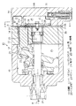
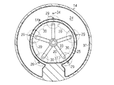
図1は前記可変容量圧縮機(以下単に圧縮機とする)の縦断面図を示し、図2は図1のA−A線断面図である。
図1において左方を圧縮機の前方とし、右方を圧縮機の後方とする。図1に示すように、圧縮機10のハウジングは、シリンダブロック11と、該シリンダブロック11の前端に接合固定されたフロントハウジング12と、シリンダブロック11の後端に弁・ポート形成体13を介して接合固定されたリヤハウジング14とを備えている。
1 is a longitudinal sectional view of the variable capacity compressor (hereinafter simply referred to as a compressor), and FIG. 2 is a sectional view taken along line AA of FIG.
In FIG. 1, the left side is the front of the compressor and the right side is the rear of the compressor. As shown in FIG. 1, the housing of the compressor 10 includes a cylinder block 11, a front housing 12 joined and fixed to the front end of the cylinder block 11, and a valve / port forming body 13 at the rear end of the cylinder block 11. And a rear housing 14 joined and fixed.

前記ハウジング内において、シリンダブロック11とフロントハウジング12との間には、クランク室15が区画形成されている。シリンダブロック11とフロントハウジング12との間には、クランク室15を挿通するようにして、駆動軸16が回転可能に支持されている。駆動軸16には、車両の走行駆動源である図示しないエンジンが作動連結されている。駆動軸16は、エンジンから動力の供給を受けて矢印Rの方向に回転される。   A crank chamber 15 is defined between the cylinder block 11 and the front housing 12 in the housing. A drive shaft 16 is rotatably supported between the cylinder block 11 and the front housing 12 so as to pass through the crank chamber 15. The drive shaft 16 is operatively connected to an engine (not shown) that is a travel drive source of the vehicle. The drive shaft 16 is supplied with power from the engine and is rotated in the direction of arrow R.

前記クランク室15内において駆動軸16には、実質的に円盤状をなすラグプレート17が一体回転可能に固定されている。クランク室15内には、カムプレートとしての斜板18が収容されている。斜板18の中央部に形成された挿通孔18aには、駆動軸16が挿通されている。ラグプレート17と斜板18との間には、ヒンジ機構19が介在されている。斜板18は、ヒンジ機構19を介したラグプレート17との間でのヒンジ連結、及び挿通孔18aを介した駆動軸16の支持により、ラグプレート17及び駆動軸16と同期回転可能であるとともに、駆動軸16の軸線T方向へのスライド移動を伴いながら駆動軸16に対して傾動可能となっている。   A lug plate 17 having a substantially disk shape is fixed to the drive shaft 16 in the crank chamber 15 so as to be integrally rotatable. A swash plate 18 as a cam plate is accommodated in the crank chamber 15. The drive shaft 16 is inserted through an insertion hole 18 a formed in the center of the swash plate 18. A hinge mechanism 19 is interposed between the lug plate 17 and the swash plate 18. The swash plate 18 can be rotated synchronously with the lug plate 17 and the drive shaft 16 by the hinge connection with the lug plate 17 via the hinge mechanism 19 and the support of the drive shaft 16 via the insertion hole 18a. The drive shaft 16 can be tilted with respect to the drive shaft 16 while being slid in the axis T direction.

前記シリンダブロック11において駆動軸16の軸線T周りには、複数(図1には一つのみ示す)のシリンダボア20が等角度間隔で前後方向(紙面左右方向)に貫通形成されている。片頭型のピストン21は、各シリンダボア20内に前後方向へ移動可能に収容されている。シリンダボア20の前後開口は、弁・ポート形成体13及びピストン21によって閉塞されており、このシリンダボア20内にはピストン21の前後方向への移動に応じて容積変化する圧縮室22が区画されている。   In the cylinder block 11, a plurality of cylinder bores 20 (only one is shown in FIG. 1) are formed around the axis T of the drive shaft 16 so as to penetrate in the front-rear direction (left-right direction in the drawing) at equal angular intervals. The single-headed piston 21 is accommodated in each cylinder bore 20 so as to be movable in the front-rear direction. The front and rear openings of the cylinder bore 20 are closed by a valve / port forming body 13 and a piston 21, and a compression chamber 22 whose volume changes in accordance with the movement of the piston 21 in the front and rear direction is defined in the cylinder bore 20. .

前記ピストン21は、一対のシュー23を介して斜板18の外周部に係留されている。ハウジング内において弁・ポート形成体13とリヤハウジング14との間には、吸入室24及び吐出室25がそれぞれ区画形成されている。   The piston 21 is anchored to the outer peripheral portion of the swash plate 18 via a pair of shoes 23. A suction chamber 24 and a discharge chamber 25 are defined between the valve / port forming body 13 and the rear housing 14 in the housing.

弁・ポート形成体13は、バルブプレート26と、バルブプレート26のシリンダブロック11側に設けられた吸入弁プレート27と、バルブプレート26のリヤハウジング14側に設けられた吐出弁プレート28とで構成されている。図1及び図3に示すように、バルブプレート26には、各シリンダボア20と相対する位置において、径方向外寄りに吸入ポート29が、径方向内寄りに吐出ポート30がそれぞれ形成されている。吸入弁プレート27には吸入ポート29と対応する位置に吸入弁31が形成され、吐出弁プレート28には吐出ポート30と対応する位置に吐出弁32が形成されている。吐出弁32はバルブプレート26に固定されたリテーナ33によって開放位置が規制されるようになっている。   The valve / port forming body 13 includes a valve plate 26, a suction valve plate 27 provided on the cylinder block 11 side of the valve plate 26, and a discharge valve plate 28 provided on the rear housing 14 side of the valve plate 26. Has been. As shown in FIGS. 1 and 3, the valve plate 26 is formed with a suction port 29 on the radially outer side and a discharge port 30 on the radially inner side at a position facing each cylinder bore 20. A suction valve 31 is formed on the suction valve plate 27 at a position corresponding to the suction port 29, and a discharge valve 32 is formed on the discharge valve plate 28 at a position corresponding to the discharge port 30. The opening position of the discharge valve 32 is regulated by a retainer 33 fixed to the valve plate 26.

圧縮機10のハウジング内には、抽気通路34及び給気通路35並びに制御弁36が設けられている。抽気通路34は、クランク室15と吸入室24とを接続する。給気通路35は、吐出室25とクランク室15とを接続する。給気通路35の途中には、電磁弁よりなる周知の制御弁36が配設されている。   In the housing of the compressor 10, an extraction passage 34, an air supply passage 35, and a control valve 36 are provided. The extraction passage 34 connects the crank chamber 15 and the suction chamber 24. The air supply passage 35 connects the discharge chamber 25 and the crank chamber 15. In the middle of the air supply passage 35, a known control valve 36 made of an electromagnetic valve is disposed.

シリンダブロック11、フロントハウジング12及びリヤハウジング14は、軽量化を図るためアルミニウム合金により形成されている。アルミニウム合金としては、例えば、Al−Si合金やAl−Si−Cu合金が使用され、ADC10やADC12が好ましく使用される。リヤハウジング14は、吸入室24の壁面(内面)と、吐出室25の壁面(内面)とに、多孔質の溶射層37が形成されている。溶射層37は、リヤハウジング14の壁を構成する材料より熱伝導率の低い金属で形成されている。この実施形態では溶射層37はニッケル(Ni)で形成されている。溶射層37は吸入室24及び吐出室25の内面全体に形成されている。溶射層37は、例えば、厚さが150〜200μmで、空隙率が5%以上に形成されている。   The cylinder block 11, the front housing 12, and the rear housing 14 are made of an aluminum alloy in order to reduce the weight. As the aluminum alloy, for example, an Al—Si alloy or an Al—Si—Cu alloy is used, and ADC 10 or ADC 12 is preferably used. In the rear housing 14, a porous sprayed layer 37 is formed on the wall surface (inner surface) of the suction chamber 24 and the wall surface (inner surface) of the discharge chamber 25. The thermal spray layer 37 is formed of a metal having a lower thermal conductivity than the material constituting the wall of the rear housing 14. In this embodiment, the sprayed layer 37 is made of nickel (Ni). The sprayed layer 37 is formed on the entire inner surfaces of the suction chamber 24 and the discharge chamber 25. The sprayed layer 37 has a thickness of 150 to 200 μm and a porosity of 5% or more, for example.

また、吸入冷媒ガスが圧縮されるまでの経路としてのシリンダボア20の内面にも、多孔質の溶射層37が形成されている。リヤハウジング14に形成された溶射層37は、特に後処理は不要であるが、シリンダボア20の内面に溶射層37を設ける場合は、溶射層37の後加工が必要となる。即ち、溶射層37が存在する状態における最終的なシリンダボア20の内径が、ピストン21の摺動が円滑に行われる値となるように、溶射層37の研削が行われる。   A porous sprayed layer 37 is also formed on the inner surface of the cylinder bore 20 as a path until the suction refrigerant gas is compressed. The thermal spray layer 37 formed on the rear housing 14 does not require any post-treatment, but when the thermal spray layer 37 is provided on the inner surface of the cylinder bore 20, post-processing of the thermal spray layer 37 is required. That is, the sprayed layer 37 is ground so that the final inner diameter of the cylinder bore 20 in a state where the sprayed layer 37 exists becomes a value that allows the piston 21 to slide smoothly.

溶射層37は、例えば、公知の高速フレーム溶射により形成される。高速フレーム溶射は、ガス炎を熱源とするフレーム溶射法の一種で、溶射ガン内部の燃焼室(チャンバー)の圧力を高めることにより、連続燃焼炎でありながら爆発溶射炎に匹敵する高速火炎を発生させ、この高速火炎により溶射粉末を基材に衝突させて皮膜を形成する方法である。高圧の酸素とプロピレンあるいは水素などの燃料ガスが燃焼室に供給されるとともに、粉末材料が搬送ガスによって炎中に供給される。   The sprayed layer 37 is formed by, for example, a known high-speed flame spraying. High-speed flame spraying is a flame spraying method that uses a gas flame as a heat source. By increasing the pressure in the combustion chamber (chamber) inside the spray gun, a high-speed flame comparable to an explosive spray flame is generated despite being a continuous combustion flame. In this method, the sprayed powder is made to collide with the substrate by this high-speed flame to form a film. High pressure oxygen and fuel gas such as propylene or hydrogen are supplied to the combustion chamber, and powder material is supplied into the flame by the carrier gas.

この実施形態では粉末材料の搬送ガス(キャリアガス)として不活性ガスを使用して予熱せずに、粉末材料を供給し、大気中で溶射を行った。粉末材料として、粒径10〜45μmのNi粉末を使用して、空孔を有する溶射層37が形成された。溶射は、できるだけ酸化物が形成されるような条件となる大気中の溶射が望ましい。   In this embodiment, an inert gas was used as a carrier gas (carrier gas) for the powder material, and the powder material was supplied and sprayed in the atmosphere without preheating. As the powder material, Ni powder having a particle size of 10 to 45 μm was used to form a sprayed layer 37 having pores. The thermal spraying is preferably performed in the atmosphere so that an oxide is formed as much as possible.

溶射条件のうち、溶射速度の空隙率に対する影響と、基材の表面粗さの空隙率に対する影響とを調べた。溶射速度(フレーム速度)を1250m/s及び2100m/sと変えて溶射を行った。   Among the spraying conditions, the influence of the spraying speed on the porosity and the influence of the surface roughness of the substrate on the porosity were investigated. Thermal spraying was performed by changing the thermal spraying speed (frame speed) to 1250 m / s and 2100 m / s.

溶射条件は次のとおりである。但し、これは一例であり、各条件は適宜変更してもよい。
燃焼用ガスとして、酸素、プロピレン及び空気の混合ガスを使用した。
The thermal spraying conditions are as follows. However, this is an example, and each condition may be changed as appropriate.
As the combustion gas, a mixed gas of oxygen, propylene and air was used.

ガス圧力:酸素(1.03MPa)、プロピレン(0.69MPa)、空気(0.52MPa)
粉末供給用キャリアガスとして窒素(0.86MPa)を使用した。
Gas pressure: oxygen (1.03 MPa), propylene (0.69 MPa), air (0.52 MPa)
Nitrogen (0.86 MPa) was used as a carrier gas for powder supply.

溶射距離:229〜279mm、溶射量:38×10−3kg/min
溶射面積:1.51m/hr/0.1mm、付着効率(概算)55%
以上の条件は溶射速度1250m/s及び2100m/sに共通で、燃焼ガスの流量が
溶射速度1250m/sと2100m/sとで異なる。燃焼ガスの流量は次のとおりである。
Thermal spraying distance: 229 to 279 mm, Thermal spraying amount: 38 × 10 −3 kg / min
Thermal spraying area: 1.51 m 2 /hr/0.1 mm, adhesion efficiency (estimated) 55%
The above conditions are common to the spraying speeds of 1250 m / s and 2100 m / s, and the flow rate of the combustion gas differs between the spraying speeds of 1250 m / s and 2100 m / s. The flow rate of the combustion gas is as follows.

溶射速度1250m/sのとき
酸素:299.7L/min、プロピレン:80.7L/min、空気:364.9L/min
溶射速度2100m/sのとき
酸素:149.9L/min、プロピレン:40.4L/min、空気:182.5L/min
その結果、表面粗さが同じ値(10μm)の基材に対して、溶射速度1250m/sで溶射を行った場合、空隙率が7.0%となり、溶射速度2100m/sで溶射を行った場合、空隙率が5.5%となった。従って、溶射速度を速くしても、空隙率は大きくならず、小さくなることが確認された。
When spraying speed is 1250 m / s Oxygen: 299.7 L / min, Propylene: 80.7 L / min, Air: 364.9 L / min
When spraying speed is 2100 m / s Oxygen: 149.9 L / min, Propylene: 40.4 L / min, Air: 182.5 L / min
As a result, when spraying was performed at a spraying speed of 1250 m / s on a substrate having the same surface roughness (10 μm), the porosity was 7.0% and spraying was performed at a spraying speed of 2100 m / s. In this case, the porosity was 5.5%. Accordingly, it was confirmed that even when the spraying speed was increased, the porosity was not increased but decreased.

また、溶射速度は1250m/sとして、基材の表面粗さを10μm及び30μmと変えた場合について溶射を行った。その結果、表面粗さが10μmの場合は、空隙率が7.0%となり、表面粗さが30μmの場合は、空隙率が1.0%となった。従って、基材の表面粗さが空隙率に影響を与えることが分かった。表面粗さが空隙率に影響を与えるのは、表面粗さ単独で影響を与えるのではなく、溶射に使用する微粉末の粒径と関係があり、溶滴が初期に表面に溶着するとき、表面粗さが細かい方が空間を作り易いためと考えられる。   The thermal spraying rate was 1250 m / s, and the thermal spraying was performed when the surface roughness of the substrate was changed to 10 μm and 30 μm. As a result, when the surface roughness was 10 μm, the porosity was 7.0%, and when the surface roughness was 30 μm, the porosity was 1.0%. Therefore, it was found that the surface roughness of the base material affects the porosity. The surface roughness affects the porosity, not the surface roughness alone, but is related to the particle size of the fine powder used for spraying, and when the droplets are initially deposited on the surface, This is probably because the surface with finer surface roughness is easier to create.

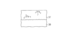
なお、空隙率は、溶射層37が形成された基材の断面の顕微鏡写真に基づいて求めた。詳述すれば、溶射層37が形成された基材の断面の顕微鏡写真では、図3に示す模式図のように、基材38上に形成された溶射層37に存在する空孔37aが識別できる。この空孔37aの面積の割合から空隙率を求めた。なお、図3では断面を示すハッチングを省略している。   In addition, the porosity was calculated | required based on the microscope picture of the cross section of the base material in which the sprayed layer 37 was formed. More specifically, in the micrograph of the cross section of the base material on which the thermal spray layer 37 is formed, the holes 37a existing in the thermal spray layer 37 formed on the base material 38 are identified as shown in the schematic diagram shown in FIG. it can. The porosity was determined from the area ratio of the holes 37a. In FIG. 3, hatching indicating a cross section is omitted.

溶射に使用する微粉末の粒径があまり小さいと、空孔37aが残り難くなるため、微粉末の粒径は10μm以上が好ましい。
次に、前記のように構成された圧縮機について、その作用を説明する。
If the particle size of the fine powder used for thermal spraying is too small, it is difficult for the pores 37a to remain. Therefore, the particle size of the fine powder is preferably 10 μm or more.
Next, the effect | action is demonstrated about the compressor comprised as mentioned above.

駆動軸16の回転に伴い斜板18が一体回転し、斜板18の回転運動がシュー23を介して各ピストン21の往復運動に変換され、各ピストン21が斜板18の傾斜角度(駆動軸16の軸線Tと直交する平面との間でなす角度)に対応したストロークで往復動される。この駆動の継続によって、圧縮室22への吸入室24からの冷媒ガスの吸入、吸入冷媒ガスの圧縮、吐出室25への圧縮冷媒ガスの吐出が順次繰り返される。吸入室24内の冷媒(本実施形態においては二酸化炭素が用いられている)ガスは、各ピストン21の上死点位置から下死点位置側への移動により、吸入ポート29及び吸入弁31を介して圧縮室22へと吸入される。圧縮室22に吸入された冷媒ガスは、ピストン21の下死点位置から上死点位置側への移動により所定の圧力にまで圧縮され、吐出ポート30及び吐出弁32を介して吐出室25へと吐出される。吐出室25に吐出された冷媒は、吐出孔(図示せず)から外部冷媒回路に送り出される。   The swash plate 18 rotates integrally with the rotation of the drive shaft 16, and the rotational motion of the swash plate 18 is converted into the reciprocating motion of each piston 21 via the shoe 23. 16 axis T and an angle formed between a plane perpendicular to the axis T) and a reciprocating motion. By continuing this drive, the suction of the refrigerant gas from the suction chamber 24 to the compression chamber 22, the compression of the suction refrigerant gas, and the discharge of the compressed refrigerant gas to the discharge chamber 25 are sequentially repeated. The refrigerant (carbon dioxide is used in this embodiment) in the suction chamber 24 moves through the suction port 29 and the suction valve 31 by moving from the top dead center position to the bottom dead center position of each piston 21. Through the compression chamber 22. The refrigerant gas sucked into the compression chamber 22 is compressed to a predetermined pressure by the movement from the bottom dead center position to the top dead center position side of the piston 21, and enters the discharge chamber 25 via the discharge port 30 and the discharge valve 32. And discharged. The refrigerant discharged into the discharge chamber 25 is sent out to an external refrigerant circuit from a discharge hole (not shown).

前記制御弁36の開度を調節することで、給気通路35を介したクランク室15への高圧な吐出ガスの導入量と、抽気通路34を介したクランク室15からのガス導出量とのバランスが制御され、クランク室15の内圧が決定される。クランク室15の内圧の変更に応じて、クランク室15の内圧と圧縮室22の内圧とのピストン21を介した差が変更され、斜板18の傾斜角度が変更される結果、ピストン21のストローク即ち圧縮機10の吐出容量が調節される。   By adjusting the opening of the control valve 36, the amount of high-pressure discharge gas introduced into the crank chamber 15 via the air supply passage 35 and the amount of gas discharged from the crank chamber 15 via the extraction passage 34 are obtained. The balance is controlled and the internal pressure of the crank chamber 15 is determined. As the internal pressure of the crank chamber 15 changes, the difference between the internal pressure of the crank chamber 15 and the internal pressure of the compression chamber 22 through the piston 21 is changed, and as a result, the inclination angle of the swash plate 18 is changed. That is, the discharge capacity of the compressor 10 is adjusted.

例えば、クランク室15の内圧が低下されると斜板18の傾斜角度が増大し、ピストン21のストロークが増大して圧縮機10の吐出容量が増大される。逆に、クランク室15の内圧が上昇されると斜板18の傾斜角度が減少し、ピストン21のストロークが減少して圧縮機10の吐出容量が減少される。   For example, when the internal pressure of the crank chamber 15 is reduced, the inclination angle of the swash plate 18 is increased, the stroke of the piston 21 is increased, and the discharge capacity of the compressor 10 is increased. Conversely, when the internal pressure of the crank chamber 15 increases, the inclination angle of the swash plate 18 decreases, the stroke of the piston 21 decreases, and the discharge capacity of the compressor 10 decreases.

圧縮機10の運転中においては、圧縮された冷媒ガスが高圧、高温となって吐出室25内に一時貯留される。リヤハウジング14が単にアルミニウム合金で形成された構成であれば、この圧縮冷媒ガスの熱は、吸入室24と吐出室25とを区画する壁14aや、リヤハウジング14の後壁14bを介して吸入室24内の冷媒ガスに伝達され易い。しかし、
吸入室24及び吐出室25の壁面に多孔質の溶射層37が形成されているため、その断熱効果によって吐出室25内の冷媒ガスの熱が吸入室24内の冷媒ガスに伝達されるのが抑制される。従って、吸入室24内の冷媒ガスが圧縮室22に吸入されるまでの間に加熱されるのを抑制することがでる。その結果、圧縮室22への実質的な冷媒ガスの吸入量が増加し、体積効率が向上して、圧縮効率も向上する。
During the operation of the compressor 10, the compressed refrigerant gas becomes high pressure and high temperature and is temporarily stored in the discharge chamber 25. If the rear housing 14 is simply formed of an aluminum alloy, the heat of the compressed refrigerant gas is sucked through the wall 14a that partitions the suction chamber 24 and the discharge chamber 25 and the rear wall 14b of the rear housing 14. It is easy to be transmitted to the refrigerant gas in the chamber 24. But,
Since the porous sprayed layer 37 is formed on the wall surfaces of the suction chamber 24 and the discharge chamber 25, the heat of the refrigerant gas in the discharge chamber 25 is transmitted to the refrigerant gas in the suction chamber 24 by the heat insulating effect. It is suppressed. Therefore, the refrigerant gas in the suction chamber 24 can be prevented from being heated before being sucked into the compression chamber 22. As a result, the substantial amount of refrigerant gas sucked into the compression chamber 22 is increased, the volumetric efficiency is improved, and the compression efficiency is also improved.

溶射層37は吸入室24及び吐出室25の壁面に密着されているため、特許文献1のように吐出室の内壁を覆うように樹脂等の断熱シートを形成したり、区画壁の外周に断熱リングを形成したりする構成と異なり、壁面と溶射層37との間に冷媒ガスが侵入する隙間が形成されるのが回避され、断熱効果の低下を回避できる。   Since the thermal spray layer 37 is in close contact with the wall surfaces of the suction chamber 24 and the discharge chamber 25, a heat insulating sheet such as a resin is formed so as to cover the inner wall of the discharge chamber as in Patent Document 1, or the outer periphery of the partition wall is insulated. Unlike the configuration in which a ring is formed, it is possible to avoid the formation of a gap for the refrigerant gas to enter between the wall surface and the sprayed layer 37, thereby avoiding a decrease in the heat insulation effect.

また、シリンダブロック11はリヤハウジング14と弁・ポート形成体13を介して接合されているため、吐出室25内の冷媒ガスの熱がシリンダブロック11に伝達される。シリンダボア20が単にシリンダブロック11に貫設された状態では、シリンダブロック11が加熱されると、シリンダボア20の壁面も加熱される。その結果、吸入行程において吸入室24から圧縮室22内に冷媒ガスが吸入される際、圧縮室22内に吸入された冷媒ガスがシリンダボア20の壁面で加熱されて膨張し、圧縮室22への実質的な冷媒ガスの吸入量が減少し、体積効率が低下する。しかし、シリンダボア20の壁面に多孔質の溶射層37が形成されているため、シリンダブロック11に吐出室25内の冷媒ガスの熱が伝達されても、シリンダボア20の壁面にはその熱が伝達されるのが抑制され、圧縮室22に吸入された冷媒ガスの加熱が抑制される。その結果、圧縮室22への実質的な冷媒ガスの吸入量が増加し、体積効率が向上して、圧縮効率も向上する。シリンダボア20に形成された溶射層37と、吸入室24及び吐出室25に形成された溶射層37とでは、後者の方が吸入冷媒ガスの加熱防止に対する効果が大きい。   Further, since the cylinder block 11 is joined to the rear housing 14 via the valve / port formation body 13, the heat of the refrigerant gas in the discharge chamber 25 is transmitted to the cylinder block 11. In a state where the cylinder bore 20 is simply provided through the cylinder block 11, when the cylinder block 11 is heated, the wall surface of the cylinder bore 20 is also heated. As a result, when the refrigerant gas is sucked into the compression chamber 22 from the suction chamber 24 in the suction stroke, the refrigerant gas sucked into the compression chamber 22 is heated by the wall surface of the cylinder bore 20 and expands. Substantial amount of refrigerant gas sucked is reduced and volumetric efficiency is lowered. However, since the porous sprayed layer 37 is formed on the wall surface of the cylinder bore 20, even if the heat of the refrigerant gas in the discharge chamber 25 is transmitted to the cylinder block 11, the heat is transmitted to the wall surface of the cylinder bore 20. And the heating of the refrigerant gas sucked into the compression chamber 22 is suppressed. As a result, the substantial amount of refrigerant gas sucked into the compression chamber 22 is increased, the volumetric efficiency is improved, and the compression efficiency is also improved. Of the thermal spray layer 37 formed in the cylinder bore 20 and the thermal spray layer 37 formed in the suction chamber 24 and the discharge chamber 25, the latter has a greater effect on preventing the refrigerant refrigerant from being heated.

この実施形態では以下の効果を有する。
(1)圧縮機10の吸入室24及び吐出室25の壁面に、それらの壁を構成する材料より熱伝導率の低い、金属製で多孔質の溶射層37が形成されている。従って、吐出室25内の冷媒ガスの熱が、吸入室24内の冷媒ガスに伝達されるのが多孔質の溶射層37により抑制される。その結果、吸入冷媒ガスの温度上昇が抑制されて、圧縮効率が向上する。また、溶射層37は前記壁面に形成されるため、圧縮機10を構成する新たな部材を設けたり、構造を変更したりせずに実施することができる。即ち、従来、金属製品の硬度、耐蝕性の向上などを目的としたコーティング技術の一種である金属の溶射を、これまで考えられていなかった断熱の目的で使用することで前記目的を達成できる。
This embodiment has the following effects.
(1) On the wall surfaces of the suction chamber 24 and the discharge chamber 25 of the compressor 10, a metal-made porous sprayed layer 37 having a lower thermal conductivity than the material constituting the walls is formed. Therefore, the porous sprayed layer 37 suppresses the heat of the refrigerant gas in the discharge chamber 25 from being transmitted to the refrigerant gas in the suction chamber 24. As a result, the temperature rise of the intake refrigerant gas is suppressed, and the compression efficiency is improved. Further, since the sprayed layer 37 is formed on the wall surface, it can be carried out without providing a new member constituting the compressor 10 or changing the structure. That is, the object can be achieved by using metal spraying, which is a kind of coating technology for the purpose of improving the hardness and corrosion resistance of metal products, for the purpose of heat insulation, which has not been considered so far.

(2)溶射層37の材料自身の熱伝導率が、シリンダブロック11及びリヤハウジング14を構成する材料の熱伝導率より低い金属であるため、溶射層37の断熱効果がより向上する。   (2) Since the thermal conductivity of the material of the thermal spray layer 37 is a metal lower than the thermal conductivity of the material constituting the cylinder block 11 and the rear housing 14, the heat insulation effect of the thermal spray layer 37 is further improved.

(3)シリンダボア20の壁面にそれらの壁を構成する材料より熱伝導率の低い金属製で多孔質の溶射層37が形成されている。従って、吸入室24から圧縮室22に吸入された冷媒ガスがシリンダボア20の壁面で加熱されて膨張するのが抑制される。その結果、吸入冷媒ガスの温度上昇が抑制されて、圧縮効率が向上する。   (3) A metal thermal spray layer 37 having a lower thermal conductivity than the material constituting the walls is formed on the wall surface of the cylinder bore 20. Therefore, the refrigerant gas sucked into the compression chamber 22 from the suction chamber 24 is suppressed from being heated and expanded by the wall surface of the cylinder bore 20. As a result, the temperature rise of the intake refrigerant gas is suppressed, and the compression efficiency is improved.

(4)シリンダブロック11、フロントハウジング12及びリヤハウジング14はアルミニウム合金製であるため、その熱伝導率が圧縮機のハウジング用に一般に使用される鉄等の金属に比較して2倍以上高いため、断熱手段を設けない場合は吸入冷媒ガスへの熱の伝達がより行われて圧縮効率がより低下する。従って、この発明のように、前記材料をアルミニウム合金製とした圧縮機においては特に有効となる。   (4) Since the cylinder block 11, the front housing 12 and the rear housing 14 are made of an aluminum alloy, their thermal conductivity is more than twice as high as that of metals such as iron generally used for compressor housings. In the case where the heat insulating means is not provided, the heat is more transferred to the suction refrigerant gas and the compression efficiency is further lowered. Therefore, the present invention is particularly effective in a compressor in which the material is made of an aluminum alloy.

(5)溶射層37の金属にはニッケルが使用されている。従って、溶射層37を構成する金属が錆び難く、また、溶射温度を特に高くする必要がないため、溶射処理が容易となる。   (5) Nickel is used for the metal of the sprayed layer 37. Accordingly, the metal constituting the sprayed layer 37 is not easily rusted, and it is not necessary to increase the spraying temperature in particular.

(6)溶射層37の空隙率を5%以上としたので、空孔37a(空隙)による断熱効果を高めることができる。
(7)溶射層37が高速フレーム溶射(HVOF)により形成されるため、フレーム温度をプラズマ溶射の場合に比較して低くでき、空孔37aを形成し易くなるとともに製造に必要なエネルギーを少なくできる。
(6) Since the porosity of the sprayed layer 37 is set to 5% or more, the heat insulation effect by the air holes 37a (voids) can be enhanced.
(7) Since the sprayed layer 37 is formed by high-speed flame spraying (HVOF), the flame temperature can be lowered as compared with the case of plasma spraying, and the holes 37a can be easily formed and the energy required for manufacturing can be reduced. .

(8)溶射に使用する微粉末の粒径を10μm以上とした場合、溶射層37に空孔37aが残り易くなり、空隙率を高めることが容易になる。
(9)圧縮機10は、シリンダブロック11に形成されたシリンダボア20内にピストン21が収容され、ピストン21の往復動により、冷媒ガスの吸入及び圧縮・吐出が行われるように構成されたピストン式圧縮機である。従って、他の圧縮機に比較して吸入室24と吐出室25との距離が近く、吐出室25内の熱が吸入室24内の吸入冷媒ガスに伝達され易い構造であるが、吸入室24及び吐出室25の壁面に溶射層37を形成するという比較的簡単な処理で吸入冷媒ガスの温度上昇を抑制することができる。
(8) When the particle size of the fine powder used for thermal spraying is 10 μm or more, voids 37a are likely to remain in the thermal spray layer 37, and the porosity is easily increased.
(9) The compressor 10 has a piston type in which a piston 21 is accommodated in a cylinder bore 20 formed in the cylinder block 11, and refrigerant gas is sucked in and compressed and discharged by reciprocating movement of the piston 21. It is a compressor. Accordingly, the suction chamber 24 and the discharge chamber 25 are closer to each other than other compressors, and the heat in the discharge chamber 25 is easily transferred to the suction refrigerant gas in the suction chamber 24. In addition, it is possible to suppress an increase in the temperature of the suction refrigerant gas by a relatively simple process of forming the sprayed layer 37 on the wall surface of the discharge chamber 25.

(10)車両空調装置の冷媒として二酸化炭素が用いられている。二酸化炭素冷媒を用いた場合には、例えばフロン冷媒を用いた場合と比較して、単位体積当たりの冷媒能力が大きく、同じ能力の圧縮機ではシリンダボア20の容積が小さく形成される。そのため、吸入室24内の冷媒ガスが加熱されて膨張し、圧縮室22への実質的な冷媒ガスの吸入量が減少した際、体積効率の低下割合が大きくなる。従って、二酸化炭素冷媒を扱う圧縮機10では、吸入冷媒ガスの加熱による膨張を抑制することによる体積効率の向上効果が大きくなる。従って、二酸化炭素冷媒の圧縮を行う圧縮機10に適用するのに特に有効であると言える。   (10) Carbon dioxide is used as a refrigerant for the vehicle air conditioner. When carbon dioxide refrigerant is used, for example, the refrigerant capacity per unit volume is large as compared with the case where chlorofluorocarbon refrigerant is used, and the capacity of the cylinder bore 20 is reduced in a compressor having the same capacity. Therefore, when the refrigerant gas in the suction chamber 24 is heated and expands, and the substantial amount of refrigerant gas sucked into the compression chamber 22 decreases, the rate of decrease in volumetric efficiency increases. Therefore, in the compressor 10 that handles the carbon dioxide refrigerant, the effect of improving the volumetric efficiency by suppressing the expansion due to the heating of the intake refrigerant gas is increased. Therefore, it can be said that it is particularly effective when applied to the compressor 10 that compresses the carbon dioxide refrigerant.

(第2の実施形態)
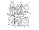
次に本発明をスクロール式圧縮機に適用した第2の実施形態を図4に従って説明する。スクロール圧縮機40は、固定スクロール41と、センターハウジング42と、モータハウジング43(一部のみ図示)とが互いに接合されている。固定スクロール41はアルミニウム合金で形成されている。回転軸44がセンターハウジング42とモータハウジング43とに回転可能に支持されている。センターハウジング42を貫通して固定スクロール41側に突出する回転軸44の端面には偏心軸44aが一体形成されている。偏心軸44aにはブッシュ45が嵌合状態で支持され、ブッシュ45には可動スクロール46が固定スクロール41と対向するようにボールベアリングを介して相対回転可能に支持されている。回転軸44はモータハウジング43内に設けられた図示しないモータにより回転される。
(Second Embodiment)
Next, a second embodiment in which the present invention is applied to a scroll compressor will be described with reference to FIG. In the scroll compressor 40, a fixed scroll 41, a center housing 42, and a motor housing 43 (only a part of which is shown) are joined together. The fixed scroll 41 is made of an aluminum alloy. A rotating shaft 44 is rotatably supported by the center housing 42 and the motor housing 43. An eccentric shaft 44 a is integrally formed on the end surface of the rotating shaft 44 that passes through the center housing 42 and protrudes toward the fixed scroll 41. A bush 45 is supported on the eccentric shaft 44a in a fitted state, and a movable scroll 46 is supported on the bush 45 through a ball bearing so as to be relatively rotatable so as to face the fixed scroll 41. The rotating shaft 44 is rotated by a motor (not shown) provided in the motor housing 43.

可動スクロール46の基板46aとセンターハウジング42との間には旋回リング47が介在されている。旋回リング47には円柱形状の複数本の自転阻止ピン48が貫通して止着されている。センターハウジング42と旋回リング47との間には環状の受圧プレート49が介在されている。受圧プレート49には自転阻止ピン48と同数の円形の自転阻止孔49aが周方向に配列されている。基板46aには自転阻止ピン48と同数の円形の自転阻止孔46bが周方向に配列されている。各自転阻止孔49a,46bはいずれも等間隔角度位置に配置されている。各自転阻止孔49a,46bには自転阻止ピン48の端部が挿入されている。   A turning ring 47 is interposed between the substrate 46 a of the movable scroll 46 and the center housing 42. A plurality of cylindrical rotation prevention pins 48 are passed through and fixed to the turning ring 47. An annular pressure receiving plate 49 is interposed between the center housing 42 and the turning ring 47. The pressure receiving plate 49 has circular rotation prevention holes 49a as many as the rotation prevention pins 48 arranged in the circumferential direction. Circular rotation prevention holes 46b having the same number as the rotation prevention pins 48 are arranged in the circumferential direction on the substrate 46a. Each of the rotation prevention holes 49a and 46b are arranged at equal angular positions. End portions of the rotation prevention pins 48 are inserted into the rotation prevention holes 49a and 46b.

固定スクロール41の基板41a及び固定側渦巻壁41b、可動スクロール46の基板46a及び可動側渦巻壁46cは、密閉空間を形成する。固定スクロール41の基板41aの中心部には密閉空間と対応する位置に吐出ポート41cが形成されている。回転軸44と一体的に回転する偏心軸44aの回転に伴い、可動スクロール46が公転し、可動スクロール46の公転に伴い、図示しない外部冷媒回路の冷媒が入口41dから固定スクロール41のハウジング内へ導入される。固定スクロール41のハウジング内へ導入された冷媒ガスは、両スクロール41,46の周縁側から基板41aと基板46aとの間へ流入する。   The substrate 41a and the fixed spiral wall 41b of the fixed scroll 41 and the substrate 46a and the movable spiral wall 46c of the movable scroll 46 form a sealed space. A discharge port 41c is formed in the center of the substrate 41a of the fixed scroll 41 at a position corresponding to the sealed space. The movable scroll 46 revolves with the rotation of the eccentric shaft 44a that rotates integrally with the rotation shaft 44, and the refrigerant of the external refrigerant circuit (not shown) enters the housing of the fixed scroll 41 from the inlet 41d with the revolution of the movable scroll 46. be introduced. The refrigerant gas introduced into the housing of the fixed scroll 41 flows between the substrates 41a and 46a from the peripheral sides of the scrolls 41 and 46.

可動スクロール46の公転に伴い、自転阻止ピン48の周面が自転阻止孔46b,49aの周面に沿って摺接し、可動スクロール46は、自転することなく公転する。可動側渦巻壁46cと固定側渦巻壁41bとの間に形成される密閉空間は、可動スクロール46の公転に伴って容積減少しつつ両スクロール41,46の中心部に向けて収束して行く。密閉空間の容積減少によって圧縮された冷媒ガスは、基板41aに形成された吐出ポート41cから吐出弁32を押しのけて吐出室25へ吐出される。   As the movable scroll 46 revolves, the peripheral surface of the rotation prevention pin 48 comes into sliding contact with the peripheral surfaces of the rotation prevention holes 46b and 49a, and the movable scroll 46 revolves without rotating. The sealed space formed between the movable-side spiral wall 46 c and the fixed-side spiral wall 41 b converges toward the center of both scrolls 41, 46 while the volume decreases with the revolution of the movable scroll 46. The refrigerant gas compressed by reducing the volume of the sealed space is discharged into the discharge chamber 25 by pushing the discharge valve 32 from the discharge port 41c formed in the substrate 41a.

モータハウジング43内と吐出室25とは固定スクロール41及びセンターハウジング42に形成された吐出通路50によって連通されている。吐出室25内の冷媒ガスは、吐出通路50を介してモータハウジング43内に吐出される。モータハウジング43内の冷媒ガスは、モータハウジング43の出口を経由して外部冷媒回路へ出てゆく。   The motor housing 43 and the discharge chamber 25 are communicated with each other by a discharge passage 50 formed in the fixed scroll 41 and the center housing 42. The refrigerant gas in the discharge chamber 25 is discharged into the motor housing 43 through the discharge passage 50. The refrigerant gas in the motor housing 43 goes out to the external refrigerant circuit via the outlet of the motor housing 43.

吐出室25の壁面と、吐出通路50の壁面と、入口41dに連通する吸入冷媒ガスの経路となる壁面には多孔性の溶射層37が形成されている。
従って、この実施形態においても、吐出室25内の高温の吐出冷媒ガスの熱がハウジングを構成する固定スクロール41の基板41aを介して吸入冷媒ガスに伝達されるのが抑制され、圧縮効率が向上する。
A porous sprayed layer 37 is formed on the wall surface of the discharge chamber 25, the wall surface of the discharge passage 50, and the wall surface serving as a path for the suction refrigerant gas communicating with the inlet 41 d.
Therefore, also in this embodiment, the heat of the high-temperature discharged refrigerant gas in the discharge chamber 25 is suppressed from being transmitted to the sucked refrigerant gas through the substrate 41a of the fixed scroll 41 constituting the housing, and the compression efficiency is improved. To do.

実施形態は前記に限定されるものではなく、例えば次のように構成してもよい。
○ 第1の実施形態において、多孔質の溶射層37は、吸入室24の壁面、吸入冷媒ガスが圧縮されるまでの経路の壁面及び吐出室25の壁面の少なくともいずれかに形成されていればよい。例えば、吸入室24の壁面のみ、シリンダボア20の壁面のみあるいは吐出室25の壁面のみに溶射層37を形成してもよい。しかし、少なくとも吸入室24及び吐出室25の壁面に溶射層37を形成する構成が、処理のしやすさ及び吸入用の冷媒ガスの加熱防止の効果の点から好ましい。
The embodiment is not limited to the above, and may be configured as follows, for example.
In the first embodiment, the porous sprayed layer 37 is formed on at least one of the wall surface of the suction chamber 24, the wall surface of the path until the suction refrigerant gas is compressed, and the wall surface of the discharge chamber 25. Good. For example, the sprayed layer 37 may be formed only on the wall surface of the suction chamber 24, only the wall surface of the cylinder bore 20, or only the wall surface of the discharge chamber 25. However, a configuration in which the sprayed layer 37 is formed at least on the wall surfaces of the suction chamber 24 and the discharge chamber 25 is preferable from the viewpoint of ease of processing and the effect of preventing heating of the refrigerant gas for suction.

○ 圧縮機10において、吸入室24及び吐出室25の配置は、図5に示すように、吸入室24が内側に配置され、吐出室25が外側に配置される構成としてもよい。
○ シリンダブロック11、フロントハウジング12、リヤハウジング14及び固定スクロール41を構成する材料はアルミニウム合金に限らずアルミニウムとしてもよい。この場合もアルミニウム合金の場合とほぼ同様の効果が得られる。
In the compressor 10, the arrangement of the suction chamber 24 and the discharge chamber 25 may be configured such that the suction chamber 24 is arranged inside and the discharge chamber 25 is arranged outside as shown in FIG.
The material which comprises the cylinder block 11, the front housing 12, the rear housing 14, and the fixed scroll 41 is not restricted to an aluminum alloy but may be aluminum. In this case, the same effect as that of the aluminum alloy can be obtained.

○ シリンダブロック11、フロントハウジング12、リヤハウジング14及び固定スクロール41を構成する材料は、圧縮機で一般に使用される鉄系の材料やその他の金属を使用してもよい。   O The material which comprises the cylinder block 11, the front housing 12, the rear housing 14, and the fixed scroll 41 may use the iron-type material generally used with a compressor, and another metal.

○ 溶射層37を構成する金属はニッケルに限らず、他の金属、例えばクロム、鉄、チタン、モリブデン、アルミニウム等の遷移金属であってもよい。また、溶射層37は合金で形成されてもよい。   The metal constituting the sprayed layer 37 is not limited to nickel, but may be other metals such as transition metals such as chromium, iron, titanium, molybdenum, and aluminum. Further, the sprayed layer 37 may be formed of an alloy.

○ 溶射層37を高速フレーム溶射で形成する際の溶射条件は前記実施形態の条件に限らない。例えば、燃焼用ガスは、酸素、プロピレン及び空気の混合ガスに限らず、酸素とプロピレンの混合ガス、酸素と水素の混合ガス、プロピレンと空気の混合ガスとしてもよい。また、粉末供給用キャリアガスとして窒素に代えて他の不活性なガス(例えば、アルゴン)を使用してもよい。   (Circle) spraying conditions at the time of forming the sprayed layer 37 by high-speed flame spraying are not restricted to the conditions of the said embodiment. For example, the combustion gas is not limited to a mixed gas of oxygen, propylene and air, but may be a mixed gas of oxygen and propylene, a mixed gas of oxygen and hydrogen, or a mixed gas of propylene and air. Moreover, instead of nitrogen, other inert gas (for example, argon) may be used as a carrier gas for powder supply.

○ 溶射層37の形成は高速フレーム溶射に限らず、例えばプラズマ溶射で形成してもよい。
○ 溶射層37の空隙率は、断熱効果の観点から大きい方が好ましい。
The formation of the sprayed layer 37 is not limited to high-speed flame spraying, and may be formed by plasma spraying, for example.
O The porosity of the sprayed layer 37 is preferably larger from the viewpoint of the heat insulating effect.

○ 圧縮機10のハウジングは、シリンダブロック11をフロントハウジング12及びリヤハウジング14で挟む構成に限らない。例えば、ハウジングをフロントハウジングとリヤハウジングとで構成し、フロントハウジング及びリヤハウジングの一方にクランク室を設け、他方のハウジングにシリンダボアを有するシリンダを嵌入した構成としてもよい。   The housing of the compressor 10 is not limited to a configuration in which the cylinder block 11 is sandwiched between the front housing 12 and the rear housing 14. For example, the housing may be constituted by a front housing and a rear housing, a crank chamber may be provided in one of the front housing and the rear housing, and a cylinder having a cylinder bore may be fitted in the other housing.

○ 可変容量型の斜板式圧縮機に限らず、両頭式や固定容量型の斜板式圧縮機に適用してもよい。斜板が駆動軸と一体回転せずに、駆動軸の回転に伴って揺動するタイプ(ワブルタイプ)の斜板式圧縮機に適用してもよい。   Not only the variable capacity swash plate compressor, but also a double-headed or fixed capacity swash plate compressor. The swash plate may be applied to a swash plate compressor of a type (wobble type) that does not rotate integrally with the drive shaft but swings as the drive shaft rotates.

○ 斜板式以外のピストン式圧縮機に適用したり、ピストン式圧縮機やスクロール式圧縮機以外の圧縮機に適用したりしてもよい。
○ 車両空調装置の冷媒として二酸化炭素を用いる圧縮機に限らず、例えば、フロン系冷媒を用いる圧縮機に適用してもよい。
O It may apply to piston type compressors other than a swash plate type, or may apply to compressors other than a piston type compressor and a scroll type compressor.
(Circle) not only the compressor which uses a carbon dioxide as a refrigerant | coolant of a vehicle air conditioner but you may apply to the compressor using a CFC-type refrigerant | coolant, for example.

○ 駆動軸16がエンジンから動力の供給を受けて回転される構成に限らず、モータで駆動される構成としてもよい。
○ 車両用空調装置に用いられる圧縮機に限らず、例えば家庭用空調装置に用いられる電動圧縮機に適用してもよい。
The drive shaft 16 is not limited to a configuration that is rotated by receiving power from the engine, and may be configured to be driven by a motor.
(Circle) not only the compressor used for a vehicle air conditioner but you may apply to the electric compressor used for a home air conditioner, for example.

○ 空調装置に用いられる圧縮機に限らず、空調装置以外の冷凍サイクル、例えば、冷蔵庫や冷凍庫の冷凍サイクルに用いられる圧縮機に適用してもよい。
以下の技術的思想(発明)は前記実施形態から把握できる。
O You may apply not only to the compressor used for an air conditioner but to the compressor used for refrigeration cycles other than an air conditioner, for example, the refrigerating cycle of a refrigerator or a freezer.
The following technical idea (invention) can be understood from the embodiment.

(1)請求項1〜請求項5のいずれか一項に記載の発明において、前記溶射層は空隙率が5%以上である。
(2)請求項1〜請求項5及び前記技術的思想(1)のいずれか一項に記載の発明において、前記溶射層は高速フレーム溶射で形成されている。
(1) In the invention according to any one of claims 1 to 5, the sprayed layer has a porosity of 5% or more.
(2) In the invention according to any one of claims 1 to 5 and the technical idea (1), the sprayed layer is formed by high-speed flame spraying.

(3)請求項1〜請求項5及び前記技術的思想(1),(2)のいずれか一項に記載の発明において、冷媒として二酸化炭素が使用されている。   (3) In the invention according to any one of claims 1 to 5 and the technical ideas (1) and (2), carbon dioxide is used as a refrigerant.

ピストン式可変容量圧縮機に具体化した一実施形態を示す縦断面図。The longitudinal cross-sectional view which shows one Embodiment actualized in the piston type variable displacement compressor. 図1のA−A線断面図。AA sectional view taken on the line AA of FIG. 溶射層と空孔との関係を示す模式図。The schematic diagram which shows the relationship between a thermal spray layer and a void | hole. 別の実施形態の圧縮機の部分断面図。The fragmentary sectional view of the compressor of another embodiment. 別の実施形態の圧縮機の部分断面図。The fragmentary sectional view of the compressor of another embodiment. 従来技術の部分断面図。The fragmentary sectional view of a prior art. 別の従来技術の部分断面図。FIG. 6 is a partial cross-sectional view of another prior art.

符号の説明Explanation of symbols

10…圧縮機、11…シリンダブロック、14a…壁、20…シリンダボア、21…ピストン、24…吸入室、25…吐出室、37…溶射層。   DESCRIPTION OF SYMBOLS 10 ... Compressor, 11 ... Cylinder block, 14a ... Wall, 20 ... Cylinder bore, 21 ... Piston, 24 ... Suction chamber, 25 ... Discharge chamber, 37 ... Sprayed layer.

Claims (5)

吸入室の壁面、吸入冷媒ガスが圧縮されるまでの経路の壁面及び吐出室の壁面の少なくともいずれかに、それらの壁を構成する材料より熱伝導率の低い、金属製で多孔質の溶射層が形成されていることを特徴とする圧縮機。   At least one of the wall surface of the suction chamber, the wall surface of the path until the suction refrigerant gas is compressed, and the wall surface of the discharge chamber are made of a metal-made porous spray layer having a lower thermal conductivity than the material constituting the walls. A compressor characterized by being formed. 前記溶射層を形成する金属は、その熱伝導率が前記壁を構成する材料の熱伝導率より低い金属である請求項1に記載の圧縮機。   The compressor according to claim 1, wherein the metal forming the sprayed layer is a metal whose thermal conductivity is lower than the thermal conductivity of the material constituting the wall. 前記材料はアルミニウム又はアルミニウム合金である請求項1又は請求項2に記載の圧縮機。   The compressor according to claim 1 or 2, wherein the material is aluminum or an aluminum alloy. 前記溶射層の金属にはニッケルが使用されている請求項1〜請求項3のいずれか一項に記載の圧縮機。   The compressor according to any one of claims 1 to 3, wherein nickel is used for the metal of the sprayed layer. 前記圧縮機は、シリンダブロックに形成されたシリンダボア内にピストンが収容され、ピストンの往復動により、冷媒ガスの吸入及び圧縮・吐出が行われるように構成されたピストン式圧縮機である請求項1〜請求項4のいずれか一項に記載の圧縮機。   The piston compressor is a piston type compressor configured such that a piston is accommodated in a cylinder bore formed in a cylinder block, and refrigerant gas is sucked in and compressed and discharged by reciprocation of the piston. The compressor according to any one of claims 4 to 5.
JP2004110195A 2004-04-02 2004-04-02 Compressor Pending JP2005291160A (en)

Priority Applications (1)

Application Number Priority Date Filing Date Title
JP2004110195A JP2005291160A (en) 2004-04-02 2004-04-02 Compressor

Applications Claiming Priority (1)

Application Number Priority Date Filing Date Title
JP2004110195A JP2005291160A (en) 2004-04-02 2004-04-02 Compressor

Publications (1)

Publication Number Publication Date
JP2005291160A true JP2005291160A (en) 2005-10-20

Family

ID=35324361

Family Applications (1)

Application Number Title Priority Date Filing Date
JP2004110195A Pending JP2005291160A (en) 2004-04-02 2004-04-02 Compressor

Country Status (1)

Country Link
JP (1) JP2005291160A (en)

Cited By (1)

* Cited by examiner, † Cited by third party
Publication number Priority date Publication date Assignee Title
JP2008538231A (en) * 2006-09-12 2008-10-16 松下電器産業株式会社 Compressor structure for cooling system

Cited By (1)

* Cited by examiner, † Cited by third party
Publication number Priority date Publication date Assignee Title
JP2008538231A (en) * 2006-09-12 2008-10-16 松下電器産業株式会社 Compressor structure for cooling system

Similar Documents

Publication Publication Date Title
US20090004030A1 (en) Compressor swash plate and method of manufacturing the same
US20020104432A1 (en) Compressor and sliding member thereof
JP2005291160A (en) Compressor
JP2006336660A (en) Method of manufacturing hermetic rotary compressor
JP2003328966A (en) Scroll compressor
JP2006207391A (en) Fluid machine
JP2009097379A (en) Refrigerant suction structure in double-headed piston type compressor
JP2755193B2 (en) Piston in compressor
JP4886370B2 (en) Fluid machinery
JP4452035B2 (en) Scroll compressor
JPH03160184A (en) Rotary compressor
US10337510B2 (en) Wear-resistant coating for oil pump cavity
JP2002155875A (en) Scroll compressor
JP2004183534A (en) Compressor
CN101504000A (en) Lubrication sealing structure of rotary compressor gas cylinder
JPH10196539A (en) Reciprocating compressor
US20050220632A1 (en) Compressor
JP2005076567A (en) Compressor
JP2012117425A (en) Compressor
JP2012117426A (en) Compressor
JP2005140072A (en) Scroll compressor
JP2001182673A (en) Sliding piston type compressor
WO2022054364A1 (en) Sliding members, and compressor and refrigeration apparatus using said sliding members
KR101147559B1 (en) Swash plate for compressor
JP2002004063A (en) Method of forming metallic film