JP2012117425A - Compressor - Google Patents

Compressor Download PDF

Info

Publication number
JP2012117425A
JP2012117425A JP2010266856A JP2010266856A JP2012117425A JP 2012117425 A JP2012117425 A JP 2012117425A JP 2010266856 A JP2010266856 A JP 2010266856A JP 2010266856 A JP2010266856 A JP 2010266856A JP 2012117425 A JP2012117425 A JP 2012117425A
Authority
JP
Japan
Prior art keywords
piston
roller
peripheral surface
compression chamber
outer peripheral
Prior art date
Legal status (The legal status is an assumption and is not a legal conclusion. Google has not performed a legal analysis and makes no representation as to the accuracy of the status listed.)
Pending
Application number
JP2010266856A
Other languages
Japanese (ja)
Inventor
Yohei Shimizu
洋平 清水
Takeo Hayashi
丈雄 林
Current Assignee (The listed assignees may be inaccurate. Google has not performed a legal analysis and makes no representation or warranty as to the accuracy of the list.)
Daikin Industries Ltd
Original Assignee
Daikin Industries Ltd
Priority date (The priority date is an assumption and is not a legal conclusion. Google has not performed a legal analysis and makes no representation as to the accuracy of the date listed.)
Filing date
Publication date
Application filed by Daikin Industries Ltd filed Critical Daikin Industries Ltd
Priority to JP2010266856A priority Critical patent/JP2012117425A/en
Publication of JP2012117425A publication Critical patent/JP2012117425A/en
Pending legal-status Critical Current

Links

Images

Abstract

PROBLEM TO BE SOLVED: To insulate heat imparted to a piston from the external peripheral surface side of the piston by a refrigerant which is compressed in a high-pressure chamber and raised in temperature by using a heat insulation region which is relatively low in heat conductivity, and to surely suppress the thermal expansion of the piston.SOLUTION: The compressor includes a cylinder having a compression chamber and a blade accommodation part communicating with the compression chamber, a front head and a rear head which are arranged at axial both ends of the cylinder, and the piston 40 arranged inside the compression chamber and the blade accommodation part. The piston 40 has an annular roller 41 arranged in the compression chamber and a blade 42 which extends from the external peripheral surface of the roller 41 and arranged so as to advance or retreat to/from the blade accommodation part. On the external peripheral surface of the piston 40, there are formed a heat insulation region in which a coating layer 44a lower in heat conductivity than a base material 43 of the piston 40, and a region in which the heat insulation region is not formed. The heat insulation region is formed at a portion which defines the high-pressure chamber 31b when the piston 40 exists in a position in which a radial gap d becomes the smallest at the external peripheral surface of the piston 40.

Description

本発明は、冷媒を圧縮するための圧縮機に関するものである。   The present invention relates to a compressor for compressing a refrigerant.

特許文献1には、圧縮室が形成されたシリンダと、シリンダの圧縮室に配置されるローラを有するピストンとを備えたロータリ圧縮機が開示されている。圧縮室は、ピストンによって冷媒が導入される低圧室と冷媒が圧縮される高圧室とに区画されている。ローラは、モータによって回転駆動されるシャフトの偏心部に装着されており、シャフトの回転に伴って、圧縮室の周壁面に沿って移動する。そして、ローラの移動に伴って、高圧室において冷媒が圧縮される。   Patent Document 1 discloses a rotary compressor including a cylinder in which a compression chamber is formed and a piston having a roller disposed in the compression chamber of the cylinder. The compression chamber is partitioned into a low pressure chamber into which the refrigerant is introduced by a piston and a high pressure chamber into which the refrigerant is compressed. The roller is mounted on an eccentric portion of a shaft that is rotationally driven by a motor, and moves along the peripheral wall surface of the compression chamber as the shaft rotates. As the roller moves, the refrigerant is compressed in the high pressure chamber.

係るロータリ圧縮機においては、ピストンの軸方向端面とこの端面に対向して配置される端板部材との間には、摺動による焼付き防止などのために、隙間が形成されている。この隙間の大きさは、冷媒や潤滑油の漏れを防止する観点から、できるだけ小さく設定されている。   In such a rotary compressor, a gap is formed between an end face in the axial direction of the piston and an end plate member disposed to face the end face to prevent seizure due to sliding. The size of this gap is set as small as possible from the viewpoint of preventing leakage of the refrigerant and the lubricating oil.

特開2010−025103号公報JP 2010-025103 A

上述のようなロータリ圧縮機においては、高圧室で圧縮され高温となった冷媒によって、シリンダおよびピストンが熱せられる。ピストンの熱膨張量がシリンダの熱膨張量よりも大きくなった場合には、上述のようなピストンの端面と端板部材との間の微小な隙間が無くなり、摺動による焼付きが生じる。   In the rotary compressor as described above, the cylinder and the piston are heated by the refrigerant compressed in the high-pressure chamber and having a high temperature. When the amount of thermal expansion of the piston becomes larger than the amount of thermal expansion of the cylinder, the above-described minute gap between the end face of the piston and the end plate member disappears, and seizure due to sliding occurs.

そこで、ピストンの外周面側からピストンに熱が与えられるのを防ぐために、ピストンの外周面を全周にわたって断熱することが考えられる。しかしながら、ピストンに対しては、その外周面側からだけでなく、内周面側からも熱が与えられる。すなわち、ピストンのローラと、このローラが装着される偏心部との間に介在する高温の潤滑油によって、ピストンが熱せられる。上述のように、ピストンの外周面を全周にわたって断熱すると、内周面側からの熱をピストンの外周面から放熱することができず、ピストンに熱が籠ってしまう。   In order to prevent heat from being applied to the piston from the outer peripheral surface side of the piston, it is conceivable to insulate the outer peripheral surface of the piston over the entire periphery. However, heat is applied to the piston not only from the outer peripheral surface side but also from the inner peripheral surface side. That is, the piston is heated by the high-temperature lubricating oil interposed between the piston roller and the eccentric portion to which the roller is mounted. As described above, when the outer peripheral surface of the piston is thermally insulated over the entire circumference, heat from the inner peripheral surface side cannot be radiated from the outer peripheral surface of the piston, and heat is generated in the piston.

そこで、本発明は、上記のような課題を解決するためになされたものであり、ピストンの熱膨張を確実に抑制できる圧縮機を提供することを目的とする。   Then, this invention is made | formed in order to solve the above subjects, and it aims at providing the compressor which can suppress the thermal expansion of a piston reliably.

第1の発明に係る圧縮機は、圧縮室および前記圧縮室に連通したブレード収容部を有するシリンダと、前記シリンダの軸方向両端にそれぞれ配置される端板部材と、前記圧縮室に配置された環状のローラ、および前記ローラの外周面から延在し且つ前記ブレード収容部に対して進退可能に配置されたブレードを有するピストンとを備えている。前記ピストンは、前記ローラが前記圧縮室の周壁面に沿って移動しつつ前記ブレードと共に前記圧縮室を高圧室と低圧室とに区画するものであって、前記ピストンの外周面は、前記ピストンの基材よりも熱伝導率の小さい断熱材料が設けられた断熱領域と、前記断熱材料が設けられていない非断熱領域とを有しており、前記断熱領域は、前記ピストンの外周面において、少なくとも、前記ローラの外周面と前記圧縮室の内周面との間のすき間が最も小さくなる位置に前記ピストンがある際に、前記高圧室を画定する部分の一部を含む領域に形成されている。   A compressor according to a first aspect of the present invention is arranged in a compression chamber and a cylinder having a blade accommodating portion communicating with the compression chamber, end plate members respectively disposed at both axial ends of the cylinder, and the compression chamber. And an annular roller, and a piston having a blade that extends from the outer peripheral surface of the roller and is disposed so as to be capable of moving forward and backward with respect to the blade housing portion. The piston partitions the compression chamber into a high-pressure chamber and a low-pressure chamber together with the blade while the roller moves along the peripheral wall surface of the compression chamber. It has a heat insulating region provided with a heat insulating material having a lower thermal conductivity than the base material, and a non-insulating region not provided with the heat insulating material, and the heat insulating region is at least on the outer peripheral surface of the piston. When the piston is at a position where the clearance between the outer peripheral surface of the roller and the inner peripheral surface of the compression chamber is the smallest, it is formed in a region including a part of a portion that defines the high-pressure chamber. .

この圧縮機では、高圧室で圧縮されて高温となった冷媒により、ピストンの外周面側からピストンに与えられる熱を、比較的熱伝導率の小さい断熱領域により断熱できる。同時に、ピストンの内周面側からピストンに与えられた熱を、断熱領域に比べて熱伝導率の大きい非断熱領域により放熱できる。したがって、ピストンの熱膨張を確実に抑制できる。   In this compressor, the heat given to the piston from the outer peripheral surface side of the piston can be insulated by the heat insulation region having a relatively low thermal conductivity by the refrigerant compressed to a high temperature in the high pressure chamber. At the same time, the heat applied to the piston from the inner peripheral surface side of the piston can be radiated by the non-insulating region having a higher thermal conductivity than the heat insulating region. Therefore, the thermal expansion of the piston can be reliably suppressed.

第2の発明に係る圧縮機は、第1の発明に係る圧縮機において、前記断熱領域は、前記ローラの外周面において、前記ブレードとの境界部を一端とし、その境界部から高圧室側へローラ下死点に向かって延びる領域に設けられている。   The compressor according to a second aspect of the invention is the compressor according to the first aspect of the invention, wherein the heat insulation region has, on the outer peripheral surface of the roller, a boundary portion with the blade as one end, and from the boundary portion to the high pressure chamber side. It is provided in a region extending toward the bottom dead center of the roller.

この圧縮機では、最も長い時間高圧室となる部分に断熱領域を設けることで、高圧室側からピストンに与えられる熱を確実に断熱できる。   In this compressor, the heat applied to the piston from the high-pressure chamber side can be reliably insulated by providing the heat-insulating region in the portion that becomes the high-pressure chamber for the longest time.

第3の発明に係る圧縮機は、第1または第2の発明に係る圧縮機において、前記シリンダは、前記圧縮室の周壁面に開口し且つ前記圧縮室に冷媒を導入するための吸入孔をさらに有し、前記非断熱領域は、少なくとも、前記ローラの外周面において、前記圧縮室の軸方向から視て前記圧縮室の軸中心から前記ローラの軸中心側に向かって延在する直線が前記吸入孔における前記ローラの移動方向下流側の端部を通る際に、前記低圧室を画定する部分を含む領域に形成されている   A compressor according to a third aspect of the invention is the compressor according to the first or second aspect of the invention, wherein the cylinder has a suction hole that opens in a peripheral wall surface of the compression chamber and introduces a refrigerant into the compression chamber. Further, the non-insulating region has a straight line extending from the axial center of the compression chamber toward the axial center side of the roller as viewed from the axial direction of the compression chamber at least on the outer peripheral surface of the roller. When passing through the end of the suction hole on the downstream side in the moving direction of the roller, the suction hole is formed in a region including a portion defining the low pressure chamber.

この圧縮機では、ローラの外周面における吸入孔の近傍に非断熱領域が形成される。したがって、吸入孔から導入される比較的低温の冷媒により、ピストンに与えられた熱を効率よく放熱できる。   In this compressor, a non-insulating region is formed in the vicinity of the suction hole on the outer peripheral surface of the roller. Therefore, the heat given to the piston can be efficiently radiated by the relatively low-temperature refrigerant introduced from the suction hole.

第4の発明に係る圧縮機は、第1〜第3のいずれかの発明に係る圧縮機において、前記非断熱領域の少なくとも一部には、前記ピストンの基材よりも熱伝導率の大きい放熱材料が設けられている。   A compressor according to a fourth aspect of the present invention is the compressor according to any one of the first to third aspects of the present invention, wherein at least a part of the non-adiabatic region has a heat dissipation greater than that of the base material of the piston. Material is provided.

この圧縮機では、放熱材料により、ピストンに与えられた熱を確実に放熱できる。   In this compressor, the heat applied to the piston can be reliably radiated by the heat radiating material.

第5の発明に係る圧縮機は、第1〜第4のいずれかの発明に係る圧縮機において、前記非断熱領域は、前記ローラの外周面において、前記圧縮室の軸方向から視て前記圧縮室の軸中心から前記ローラの軸中心側に向かって延在する直線が前記吸入孔における前記ローラの移動方向下流側の端部を通る際に、前記低圧室を画定する部分に形成された凹部および凸部の少なくともいずれか一方を有している   A compressor according to a fifth invention is the compressor according to any one of the first to fourth inventions, wherein the non-adiabatic region is the compression when viewed from the axial direction of the compression chamber on the outer peripheral surface of the roller. A recess formed in a portion defining the low-pressure chamber when a straight line extending from the axial center of the chamber toward the axial center side of the roller passes through the end of the suction hole on the downstream side in the moving direction of the roller. And at least one of the convex portions

この圧縮機では、凹部や凸部によりローラの外周面の表面積を増加させることで、ピストンに与えられた熱を確実に放熱できる。   In this compressor, the heat given to the piston can be reliably radiated by increasing the surface area of the outer peripheral surface of the roller by the concave portion or the convex portion.

第6の発明に係る圧縮機は、第1〜第5のいずれかの発明に係る圧縮機において、前記ピストンの軸方向端面は、前記ピストンの基材よりも熱伝導率の小さい断熱材料が設けられた断熱領域を有している。   A compressor according to a sixth aspect of the present invention is the compressor according to any one of the first to fifth aspects of the present invention, wherein the end surface in the axial direction of the piston is provided with a heat insulating material having a lower thermal conductivity than the base material of the piston. A thermal insulation region.

この圧縮機では、端板部材のシリンダ側とは反対側の熱が、端板部材を介してピストンに伝わるのを防ぐことができる。   In this compressor, the heat on the opposite side of the end plate member to the cylinder side can be prevented from being transmitted to the piston through the end plate member.

以上の説明に述べたように、本発明によれば、以下の効果が得られる。   As described above, according to the present invention, the following effects can be obtained.

第1の発明では、高圧室で圧縮されて高温となった冷媒により、ピストンの外周面側からピストンに与えられる熱を、比較的熱伝導率の小さい断熱領域により断熱できる。同時に、ピストンの内周面側からピストンに与えられた熱を、断熱領域に比べて熱伝導率の大きい非断熱領域により放熱できる。したがって、ピストンの熱膨張を確実に抑制できる。   In the first invention, the heat given to the piston from the outer peripheral surface side of the piston can be insulated by the heat insulation region having a relatively low thermal conductivity by the refrigerant which has been compressed in the high pressure chamber and becomes high temperature. At the same time, the heat applied to the piston from the inner peripheral surface side of the piston can be radiated by the non-insulating region having a higher thermal conductivity than the heat insulating region. Therefore, the thermal expansion of the piston can be reliably suppressed.

第2の発明では、最も長い時間高圧室となる部分に断熱領域を設けることで、高圧室側からピストンに与えられる熱を確実に断熱できる。   In 2nd invention, the heat | fever given to a piston from the high pressure chamber side can be reliably insulated by providing a heat insulation area | region in the part used as a high pressure chamber for the longest time.

第3の発明では、ローラの外周面における吸入孔の近傍に非断熱領域が形成される。したがって、吸入孔から導入される比較的低温の冷媒により、ピストンに与えられた熱を効率よく放熱できる。   In the third invention, a non-insulating region is formed in the vicinity of the suction hole on the outer peripheral surface of the roller. Therefore, the heat given to the piston can be efficiently radiated by the relatively low-temperature refrigerant introduced from the suction hole.

第4の発明では、放熱材料により、ピストンに与えられた熱を確実に放熱できる。   In the fourth invention, the heat given to the piston can be reliably radiated by the heat radiating material.

第5の発明では、凹部や凸部によりローラの外周面の表面積を増加させることで、ピストンに与えられた熱を確実に放熱できる。   In 5th invention, the heat given to the piston can be radiated reliably by making the surface area of the outer peripheral surface of a roller increase by a recessed part or a convex part.

第6の発明では、端板部材のシリンダ側とは反対側の熱が、端板部材を介してピストンに伝わるのを防ぐことができる。   In 6th invention, it can prevent that the heat on the opposite side to the cylinder side of an end plate member is transmitted to a piston via an end plate member.

本発明の第1実施形態に係る圧縮機の概略断面図である。1 is a schematic cross-sectional view of a compressor according to a first embodiment of the present invention. 図1のA−A線に沿った断面図であって、シリンダ内でのピストンの動作を示す図である。It is sectional drawing along the AA line of FIG. 1, Comprising: It is a figure which shows operation | movement of the piston in a cylinder. 図1に示した圧縮機のピストンの斜視図である。It is a perspective view of the piston of the compressor shown in FIG. 図1の部分拡大図を模式的に示した図である。It is the figure which showed typically the elements on larger scale of FIG. 図2に示すようにローラが移動する際のローラの外周面と圧縮室の周壁面との間の径方向隙間の大きさの変化を示すグラフである。It is a graph which shows the change of the magnitude | size of the radial clearance between the outer peripheral surface of a roller and the surrounding wall surface of a compression chamber when a roller moves as shown in FIG. 図3に示したピストンの平面図であり、(a)は上面図、(b)は高圧室側から見た側面図、(c)は低圧室側から見た側面図である。FIG. 4 is a plan view of the piston shown in FIG. 3, wherein (a) is a top view, (b) is a side view seen from the high pressure chamber side, and (c) is a side view seen from the low pressure chamber side. 本発明の第2実施形態に係る圧縮機の概略断面図である。It is a schematic sectional drawing of the compressor which concerns on 2nd Embodiment of this invention. 図7のB−B線に沿った断面図である。It is sectional drawing along the BB line of FIG. 第1実施形態の第1変形例に係る圧縮機のピストンの斜視図である。It is a perspective view of the piston of the compressor concerning the 1st modification of a 1st embodiment. 第1実施形態の第2変形例に係る圧縮機のピストンの斜視図である。It is a perspective view of the piston of the compressor concerning the 2nd modification of a 1st embodiment. 第1実施形態の第3変形例に係る圧縮機の図2(b)に相当する図である。It is a figure equivalent to FIG.2 (b) of the compressor which concerns on the 3rd modification of 1st Embodiment.

<第1実施形態>
以下、本発明の第1実施形態について説明する。
本実施形態は、1シリンダ型のロータリ圧縮機に本発明を適用した一例である。
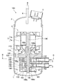
図1に示すように、本実施形態の圧縮機1は、密閉ケーシング2と、密閉ケーシング2内に配置される圧縮機構10および駆動機構6を備えている。なお、図1は、駆動機構6の断面を示すハッチングを省略して表示している。この圧縮機1は、例えば、空調装置などの冷凍サイクルに組み込まれて使用され、後述する吸入管3から導入された冷媒(本実施形態では、CO2)を圧縮して排出管4から排出する。図1の上下方向を単に上下方向として、圧縮機1について以下説明する。
<First Embodiment>
The first embodiment of the present invention will be described below.
The present embodiment is an example in which the present invention is applied to a one-cylinder rotary compressor.
As shown in FIG. 1, the compressor 1 of the present embodiment includes a sealed casing 2, a compression mechanism 10 and a drive mechanism 6 disposed in the sealed casing 2. In FIG. 1, hatching indicating a cross section of the drive mechanism 6 is omitted. The compressor 1 is used by being incorporated in a refrigeration cycle such as an air conditioner, for example, and compresses a refrigerant (CO2 in this embodiment) introduced from a suction pipe 3 to be described later and discharges it from a discharge pipe 4. The compressor 1 will be described below with the vertical direction in FIG.

密閉ケーシング2は、両端が塞がれた円筒状の容器であり、その上部には、圧縮された冷媒を排出するための排出管4と、駆動機構6の後述する固定子7bのコイルに電流を供給するためのターミナル端子5が設けられている。なお、図1では、コイルとターミナル端子5とを接続する配線は省略して表示している。また。密閉ケーシング2の側部には、圧縮機1に冷媒を導入するための吸入管3が設けられている。また、密閉ケーシング2内の下部には、圧縮機構10の摺動部の動作を滑らかにするための潤滑油Lが貯留されている。密閉ケーシング2の内部には、駆動機構6と、圧縮機構10とが上下に並んで配置されている。   The hermetic casing 2 is a cylindrical container with both ends closed. An upper portion of the hermetic casing 2 has a discharge pipe 4 for discharging a compressed refrigerant and a coil of a stator 7b (to be described later) of the drive mechanism 6 as a current. Is provided with a terminal terminal 5. In FIG. 1, the wiring connecting the coil and the terminal terminal 5 is not shown. Also. A suction pipe 3 for introducing a refrigerant into the compressor 1 is provided on the side of the closed casing 2. In addition, a lubricating oil L for smoothing the operation of the sliding portion of the compression mechanism 10 is stored in the lower part of the sealed casing 2. Inside the sealed casing 2, a drive mechanism 6 and a compression mechanism 10 are arranged vertically.

駆動機構6は、圧縮機構10を駆動するために設けられており、駆動源となるモータ7と、このモータ7に取り付けられたシャフト8とから構成されている。   The drive mechanism 6 is provided to drive the compression mechanism 10 and includes a motor 7 serving as a drive source and a shaft 8 attached to the motor 7.

モータ7は、密閉ケーシング2の内周面に固定されている略円環状の固定子7bと、この固定子7bの径方向内側にエアギャップを介して配置される回転子7aとを備えている。回転子7aは磁石(図示省略)を有し、固定子7bはコイルを有している。モータ7は、コイルに電流を流すことによって発生する電磁力によって、回転子7aを回転させる。また、固定子7bの外周面は、全周にわたって密閉ケーシング2の内周面に密着しているわけではなく、固定子7bの外周面には、上下方向に延び且つモータ7の上下の空間を連通させる複数の凹部(図示省略)が、周方向に並んで形成されている。   The motor 7 includes a substantially annular stator 7b fixed to the inner peripheral surface of the hermetic casing 2, and a rotor 7a disposed on the radially inner side of the stator 7b via an air gap. . The rotor 7a has a magnet (not shown), and the stator 7b has a coil. The motor 7 rotates the rotor 7a by an electromagnetic force generated by passing a current through the coil. Further, the outer peripheral surface of the stator 7b is not in close contact with the inner peripheral surface of the hermetic casing 2 over the entire periphery. The outer peripheral surface of the stator 7b extends in the vertical direction and has a space above and below the motor 7. A plurality of recesses (not shown) to be communicated are formed side by side in the circumferential direction.

シャフト8は、モータ7の駆動力を圧縮機構10に伝達するために設けられており、回転子7aの内周面に固定されて、回転子7aと一体的に回転する。また、シャフト8は、後述する圧縮室31内となる位置に、偏心部8aを有している。偏心部8aは、円柱状に形成されており、その軸心がシャフト8の回転中心から偏心している。この偏心部8aには、圧縮機構10の後述するローラ41が装着されている。   The shaft 8 is provided to transmit the driving force of the motor 7 to the compression mechanism 10, is fixed to the inner peripheral surface of the rotor 7a, and rotates integrally with the rotor 7a. The shaft 8 has an eccentric portion 8a at a position in the compression chamber 31 described later. The eccentric portion 8 a is formed in a columnar shape, and its axis is eccentric from the rotation center of the shaft 8. A roller 41 (to be described later) of the compression mechanism 10 is mounted on the eccentric portion 8a.

また、シャフト8の下側略半分の内部には、上下方向に延在する給油路8bが形成されている。この給油路8bの下端部には、シャフト8の回転に伴って潤滑油Lを給油路8b内に吸い上げるための螺旋羽根形状のポンプ部材(図示省略)が挿入されている。さらに、シャフト8には、給油路8b内の潤滑油Lをシャフト8の外側に排出するための複数の排出孔8cが形成されている。   An oil supply passage 8b extending in the vertical direction is formed inside the lower half of the shaft 8. A spiral blade-shaped pump member (not shown) for sucking the lubricating oil L into the oil supply passage 8b as the shaft 8 rotates is inserted into the lower end portion of the oil supply passage 8b. Further, the shaft 8 is formed with a plurality of discharge holes 8 c for discharging the lubricating oil L in the oil supply passage 8 b to the outside of the shaft 8.

圧縮機構10は、密閉ケーシング2の内周面に固定されるフロントヘッド(端板部材)20と、フロントヘッド20の上側に配置されるマフラー11と、フロントヘッド20の下側に配置されるシリンダ30と、シリンダ30の内部に配置されるピストン40と、シリンダ30の下側に配置されるリアヘッド(端板部材)50とを備えている。詳細は後述するが、図2に示すように、シリンダ30は、略円環状の部材であって、その中央部に圧縮室31が形成されている。シリンダ30は、リアヘッド50と共に、フロントヘッド20の下側にボルトにより固定されている。なお、図2は、シリンダ30に形成されているボルト孔は省略して表示している。   The compression mechanism 10 includes a front head (end plate member) 20 that is fixed to the inner peripheral surface of the sealed casing 2, a muffler 11 that is disposed above the front head 20, and a cylinder that is disposed below the front head 20. 30, a piston 40 disposed inside the cylinder 30, and a rear head (end plate member) 50 disposed below the cylinder 30. Although details will be described later, as shown in FIG. 2, the cylinder 30 is a substantially annular member, and a compression chamber 31 is formed at the center thereof. The cylinder 30 is fixed to the lower side of the front head 20 together with the rear head 50 by bolts. In FIG. 2, bolt holes formed in the cylinder 30 are omitted.

図1に示すように、フロントヘッド20は、略円環状の部材であって、その中央部に、シャフト8が回転可能に挿通される軸受け孔21が形成されている。フロントヘッド20の外周面は、密閉ケーシング2の内周面にスポット溶接などによって固定されている。フロントヘッド20の下面は、シリンダ30の圧縮室31の上端を閉塞している。フロントヘッド20には、圧縮室31において圧縮された冷媒を吐出するための吐出孔22(図2参照)が形成されている。吐出孔22は、上下方向から視て、シリンダ30の後述するブレード収容部33の近傍に形成されている。図示は省略するが、フロントヘッド20の上面には、圧縮室31内の圧力に応じて吐出孔22を開閉する弁機構が取り付けられている。また、フロントヘッド20のシリンダ30よりも径方向外側の部分には、複数の油戻し孔23が周方向に並んで形成されている。フロントヘッド20は、金属材料で形成されている。   As shown in FIG. 1, the front head 20 is a substantially annular member, and a bearing hole 21 through which the shaft 8 is rotatably inserted is formed at the center thereof. The outer peripheral surface of the front head 20 is fixed to the inner peripheral surface of the sealed casing 2 by spot welding or the like. The lower surface of the front head 20 closes the upper end of the compression chamber 31 of the cylinder 30. A discharge hole 22 (see FIG. 2) for discharging the refrigerant compressed in the compression chamber 31 is formed in the front head 20. The discharge hole 22 is formed in the vicinity of a blade accommodating portion 33 (described later) of the cylinder 30 when viewed from the up-down direction. Although not shown, a valve mechanism that opens and closes the discharge hole 22 according to the pressure in the compression chamber 31 is attached to the upper surface of the front head 20. In addition, a plurality of oil return holes 23 are formed in the circumferential direction in the radially outer portion of the front head 20 than the cylinder 30. The front head 20 is made of a metal material.

リアヘッド50は、略円環状の部材であって、その中央部にシャフト8が回転可能に挿通される軸受け孔51が形成されている。リアヘッド50は、シリンダ30の圧縮室31の下端を閉塞している。リアヘッド50は、金属材料で形成されている。   The rear head 50 is a substantially annular member, and a bearing hole 51 through which the shaft 8 is rotatably inserted is formed at the center thereof. The rear head 50 closes the lower end of the compression chamber 31 of the cylinder 30. The rear head 50 is made of a metal material.

マフラー11は、フロントヘッド20の吐出孔22から冷媒が吐出される際の騒音を低減するために設けられている。マフラー11は、フロントヘッド20の上面にボルトによって取り付けられ、フロントヘッド20との間にマフラー空間Mを形成している。また、図示は省略するが、マフラー11には、マフラー空間M内の冷媒を排出するためのマフラー吐出孔が形成されている。   The muffler 11 is provided to reduce noise when the refrigerant is discharged from the discharge hole 22 of the front head 20. The muffler 11 is attached to the upper surface of the front head 20 with bolts, and forms a muffler space M between the front head 20 and the muffler 11. Although not shown, the muffler 11 is formed with a muffler discharge hole for discharging the refrigerant in the muffler space M.

図1および図2に示すように、シリンダ30には、上述した圧縮室31と、圧縮室31内に冷媒を導入するための吸入孔32と、ブレード収容部33が形成されている。なお、図2は、図1のA−A線断面図であって、フロントヘッド20の吐出孔22は本来表れないが、説明の便宜上表示している。シリンダ30は、金属材料で形成されている。   As shown in FIGS. 1 and 2, the cylinder 30 is formed with the above-described compression chamber 31, a suction hole 32 for introducing a refrigerant into the compression chamber 31, and a blade accommodating portion 33. 2 is a cross-sectional view taken along the line AA in FIG. 1, and the discharge holes 22 of the front head 20 are not originally shown, but are shown for convenience of explanation. The cylinder 30 is made of a metal material.

吸入孔32は、シリンダ30の径方向に延在して形成されている。吸入孔32の一端は、圧縮室31の周壁面に開口した吸入口32aとなっている。また、吸入孔32の吸入口32a側とは反対側の端部には、吸入管3の先端が内嵌されている。   The suction hole 32 is formed to extend in the radial direction of the cylinder 30. One end of the suction hole 32 is a suction port 32 a that is opened in the peripheral wall surface of the compression chamber 31. The tip of the suction pipe 3 is fitted into the end of the suction hole 32 opposite to the suction port 32a.

ブレード収容部33は、シリンダ30を上下方向に貫通しており、圧縮室31と連通している。ブレード収容部33は、圧縮室31の径方向に延在している。ブレード収容部33は、上下方向から視て、吸入孔32とフロントヘッド20の吐出孔22との間の位置に形成されている。このブレード収容部33内には、一対のブッシュ34が配置されている。一対のブッシュ34は、略円柱状の部材を半分割した形状に形成されている。この一対のブッシュ34の間にブレード42が配置されている。一対のブッシュ34は、その間にブレード42が配置された状態で、ブレード収容部33内において周方向に揺動可能となっている。   The blade accommodating portion 33 penetrates the cylinder 30 in the vertical direction and communicates with the compression chamber 31. The blade housing portion 33 extends in the radial direction of the compression chamber 31. The blade accommodating portion 33 is formed at a position between the suction hole 32 and the discharge hole 22 of the front head 20 when viewed from the vertical direction. A pair of bushes 34 is disposed in the blade accommodating portion 33. The pair of bushes 34 is formed in a shape in which a substantially cylindrical member is divided into half. A blade 42 is disposed between the pair of bushes 34. The pair of bushes 34 can swing in the circumferential direction in the blade housing portion 33 with the blade 42 disposed therebetween.

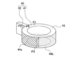
図3に示すように、ピストン40は、円環状のローラ41と、このローラ41の外周面から径方向外側に延在するブレード42とから構成されている。図2に示すように、ローラ41は、偏心部8aの外周面に相対回転可能に装着されて、圧縮室31内に配置されている。ブレード42は、ブレード収容部33に配置された一対のブッシュ34の間に進退可能に配置されている。   As shown in FIG. 3, the piston 40 includes an annular roller 41 and a blade 42 that extends radially outward from the outer peripheral surface of the roller 41. As shown in FIG. 2, the roller 41 is mounted on the outer peripheral surface of the eccentric portion 8 a so as to be relatively rotatable, and is disposed in the compression chamber 31. The blade 42 is disposed between the pair of bushes 34 disposed in the blade accommodating portion 33 so as to advance and retreat.

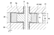
また、図4に示すように、ピストン40の上下方向長さH1は、圧縮室31の上下方向長さH2よりも僅かに小さく、その差は例えば10〜30μm程度である。また、ローラ41の外径は、偏心部8aに装着された状態でローラ41の外周面と圧縮室31の周壁面との間に、微小な隙間d(以下、この隙間を径方向隙間dという)が生じる大きさとなっている。この径方向隙間dの大きさは、後で詳述するように、圧縮機1の駆動中に、例えば10〜100μm程度の範囲内で変化する。このように径方向隙間dが微小であるので、図2(b)〜図2(d)に示すように、ブレード42がブレード収容部33から圧縮室31側に出ている状態では、ローラ41の外周面と圧縮室31の周壁面との間に形成される空間は、ブレード42によって低圧室31aと高圧室31bに区画される。   Further, as shown in FIG. 4, the vertical length H1 of the piston 40 is slightly smaller than the vertical length H2 of the compression chamber 31, and the difference is, for example, about 10 to 30 μm. The outer diameter of the roller 41 is a small gap d (hereinafter referred to as a radial gap d) between the outer peripheral surface of the roller 41 and the peripheral wall surface of the compression chamber 31 in a state where the roller 41 is mounted on the eccentric portion 8a. ). As will be described later in detail, the size of the radial gap d varies within a range of about 10 to 100 μm, for example, while the compressor 1 is being driven. Since the radial gap d is thus small, as shown in FIGS. 2B to 2D, the roller 41 is in a state where the blade 42 protrudes from the blade accommodating portion 33 toward the compression chamber 31. A space formed between the outer peripheral surface of the compression chamber 31 and the peripheral wall surface of the compression chamber 31 is partitioned by the blade 42 into a low pressure chamber 31a and a high pressure chamber 31b.

図3、図4に示すように、本実施形態のピストン40は、基材43と、基材43の表面を被覆する薄膜状のコーティング層44a、44bとから構成されている。基材43は、例えば、熱伝導率48W/mkの鋳鉄などの金属材料からなる。基材43の外形は、ほぼピストン40の外形を構成している。コーティング層44a、44bは、いずれも基材43の表面におけるピストン40に外周面に対応する部分の一部を被覆している。つまり、コーティング層44a、44bは、ピストン40の外周面の一部に形成されている。   As shown in FIGS. 3 and 4, the piston 40 of the present embodiment includes a base material 43 and thin coating layers 44 a and 44 b that cover the surface of the base material 43. The base material 43 is made of a metal material such as cast iron having a thermal conductivity of 48 W / mk, for example. The outer shape of the base material 43 substantially constitutes the outer shape of the piston 40. Each of the coating layers 44 a and 44 b covers the piston 40 on the surface of the base material 43 with a part corresponding to the outer peripheral surface. That is, the coating layers 44 a and 44 b are formed on a part of the outer peripheral surface of the piston 40.

コーティング層44aは、基材43よりも熱伝導率が小さい、例えば、熱伝導率13W/mkのニッケルクロム合金などの金属材料からなる。したがって、ピストン40の外周面においてコーティング層44aが形成された領域は断熱領域となっている。なお、ピストン40の外周面においてコーティング層44aが形成されていない領域は非断熱領域となっている。コーティング層44bは、上記の非断熱領域の一部に形成されており、基材43よりも熱伝導率が大きい、例えば、熱伝導率236W/mkのアルミニウムなどの金属材料からなる。したがって、コーティング層44bが形成された領域は放熱領域となっている。ピストン40の外周面における断熱領域と放熱領域との具体的な位置関係については、後で詳述する。   The coating layer 44a is made of a metal material such as a nickel chromium alloy having a thermal conductivity smaller than that of the base material 43, for example, a thermal conductivity of 13 W / mk. Therefore, the region where the coating layer 44a is formed on the outer peripheral surface of the piston 40 is a heat insulating region. In addition, the area | region in which the coating layer 44a is not formed in the outer peripheral surface of the piston 40 is a non-adiabatic area. The coating layer 44b is formed in a part of the non-insulating region, and is made of a metal material such as aluminum having a thermal conductivity higher than that of the base material 43, for example, a thermal conductivity of 236 W / mk. Therefore, the region where the coating layer 44b is formed is a heat dissipation region. The specific positional relationship between the heat insulating area and the heat radiating area on the outer peripheral surface of the piston 40 will be described in detail later.

次に、本実施形態の圧縮機1の動作について、図2(a)〜図2(d)、および図5を参照して説明する。図2(a)は、ピストン40が上死点にある状態を示しており、図2(b)〜図2(d)は、図2(a)の状態からのシャフト8の回転角度が、それぞれ、α°、180°(下死点)、β°である状態を示している。ここで、図2(b)に示すシャフト8の回転角度がα°である状態とは、圧縮室31の上下方向から視て圧縮室31の軸中心からローラ41の軸中心側に向かって延在する直線Lが吸入孔32におけるローラ41の移動方向(図中時計回り方向)下流側の端部を通る状態を意味する。また、図2(d)に示すシャフト8の回転角度がβ°である状態とは、後述するように、径方向隙間dが最も小さくなる状態を意味する。図5に示すグラフは、シャフト8の回転角度θに対する径方向隙間dの変化の概略(図中実線で示す)と、高圧室31b内の圧力変化の概略(図中破線で示す)とを描いたものである。   Next, operation | movement of the compressor 1 of this embodiment is demonstrated with reference to Fig.2 (a)-FIG.2 (d), and FIG. 2A shows a state where the piston 40 is at the top dead center, and FIGS. 2B to 2D show that the rotation angle of the shaft 8 from the state of FIG. The states are α °, 180 ° (bottom dead center), and β °, respectively. Here, the state where the rotation angle of the shaft 8 shown in FIG. 2B is α ° extends from the axial center of the compression chamber 31 toward the axial center side of the roller 41 when viewed from the vertical direction of the compression chamber 31. This means that the existing straight line L passes through the downstream end of the suction hole 32 in the moving direction of the roller 41 (clockwise direction in the drawing). Further, the state where the rotation angle of the shaft 8 shown in FIG. 2D is β ° means a state where the radial gap d is the smallest, as will be described later. The graph shown in FIG. 5 outlines the change of the radial gap d with respect to the rotation angle θ of the shaft 8 (shown by a solid line in the figure) and the outline of the pressure change in the high pressure chamber 31b (shown by a broken line in the figure). It is a thing.

吸入管3から吸入孔32を介して圧縮室31に冷媒を供給しつつ、モータ7の駆動によりシャフト8を回転させると、図2(a)〜図2(d)に示すように、偏心部8aに装着されたローラ41は、圧縮室31の周壁面に沿って移動する。これにより、圧縮室31内で冷媒が圧縮される。冷媒が圧縮される工程について、以下、詳細に説明する。   When the shaft 8 is rotated by driving the motor 7 while supplying the refrigerant from the suction pipe 3 to the compression chamber 31 through the suction hole 32, as shown in FIGS. 2 (a) to 2 (d), the eccentric portion The roller 41 attached to 8 a moves along the peripheral wall surface of the compression chamber 31. Thereby, the refrigerant is compressed in the compression chamber 31. Hereinafter, the process of compressing the refrigerant will be described in detail.

図2(a)の状態から偏心部8aが図中の矢印方向に回転すると、図2(b)に示すように、ローラ41の外周面と圧縮室31の周壁面とによって形成される空間が、低圧室31aと高圧室31bに区画される。さらに偏心部8aが回転すると、図2(b)〜図2(d)に示すように、低圧室31aの容積が大きくなるため、吸入管3から吸入孔32を介して低圧室31a内に冷媒が吸い込まれていく。同時に、高圧室31bの容積が小さくなるため、高圧室31bにおいて冷媒が圧縮される。なお、図2(b)に示すように、シャフト8の回転角度がα°となった時、ローラ41の外周面が、吸入孔32におけるローラ41の移動方向下流側の端部に最も近づく。このとき、ローラ41の外周面において、吸入孔32におけるローラ41の移動方向下流側の端部に最も近づく部分をP1で示す。   When the eccentric portion 8a rotates in the direction of the arrow in the figure from the state of FIG. 2A, a space formed by the outer peripheral surface of the roller 41 and the peripheral wall surface of the compression chamber 31 is formed as shown in FIG. The chamber is divided into a low pressure chamber 31a and a high pressure chamber 31b. When the eccentric portion 8a further rotates, the volume of the low pressure chamber 31a increases as shown in FIGS. 2 (b) to 2 (d). Therefore, the refrigerant enters the low pressure chamber 31a from the suction pipe 3 through the suction hole 32. Is sucked in. At the same time, since the volume of the high pressure chamber 31b is reduced, the refrigerant is compressed in the high pressure chamber 31b. As shown in FIG. 2B, when the rotation angle of the shaft 8 becomes α °, the outer peripheral surface of the roller 41 comes closest to the end of the suction hole 32 on the downstream side in the moving direction of the roller 41. At this time, the portion of the outer peripheral surface of the roller 41 that is closest to the end of the suction hole 32 on the downstream side in the moving direction of the roller 41 is denoted by P1.

図5に示すように、ローラ41の外周面と圧縮室31の周壁面との間の径方向隙間dの大きさは、シャフト8が上死点から90°回転するまでの間に最大となり、そこから次第に小さくなる。そして、図2(d)に示すように、シャフト8の回転角度がβ°となった時、径方向隙間dが最小となる。なお、回転角度β°は、180°よりも大きく330°以下である。このとき、ローラ41の外周面において圧縮室31の周壁面に最も近づく部分をP2で示す。また、このとき、ブレード42の側面において、高圧室31bを画定している部分のローラ41側とは反対側の端部をP3で示す。   As shown in FIG. 5, the size of the radial gap d between the outer peripheral surface of the roller 41 and the peripheral wall surface of the compression chamber 31 is maximized until the shaft 8 is rotated 90 ° from the top dead center. From there it gradually becomes smaller. As shown in FIG. 2D, when the rotation angle of the shaft 8 becomes β °, the radial clearance d is minimized. The rotation angle β ° is greater than 180 ° and equal to or less than 330 °. At this time, a portion closest to the peripheral wall surface of the compression chamber 31 on the outer peripheral surface of the roller 41 is indicated by P2. Further, at this time, an end portion on the side opposite to the roller 41 side of the portion defining the high pressure chamber 31b on the side surface of the blade 42 is indicated by P3.

そして、高圧室31b内の圧力が所定の圧力以上になった時点で、フロントヘッド20に設けられた弁機構が開弁して、高圧室31b内の冷媒が吐出孔22を介してマフラー空間Mに吐出される。なお、径方向隙間dが最小となった時(すなわち、シャフト8の回転角度がβ°となった時)、高圧室31b内の冷媒の圧力は、弁機構が開弁する所定の圧力に達する。その後、図2(a)の状態に戻り、高圧室31bからの冷媒の吐出が完了する。この工程を繰り返すことにより、吸入管3から圧縮室31に供給された冷媒が連続的に圧縮されて排出される。マフラー空間Mに吐出された冷媒は、マフラー11のマフラー吐出孔(図示省略)から圧縮機構10の外に吐出される。   Then, when the pressure in the high pressure chamber 31b becomes equal to or higher than a predetermined pressure, the valve mechanism provided in the front head 20 opens, and the refrigerant in the high pressure chamber 31b passes through the discharge hole 22 and the muffler space M Discharged. When the radial gap d is minimized (that is, when the rotation angle of the shaft 8 is β °), the pressure of the refrigerant in the high pressure chamber 31b reaches a predetermined pressure at which the valve mechanism opens. . Thereafter, the state returns to the state of FIG. 2A, and the discharge of the refrigerant from the high pressure chamber 31b is completed. By repeating this process, the refrigerant supplied from the suction pipe 3 to the compression chamber 31 is continuously compressed and discharged. The refrigerant discharged into the muffler space M is discharged out of the compression mechanism 10 through a muffler discharge hole (not shown) of the muffler 11.

上述のような圧縮機構10から吐出された冷媒は、固定子7bと回転子7aとの間のエアギャップなどを通過した後、最終的に、排出管4から密閉ケーシング2の外に排出される。このとき、シャフト8の排出孔8cから圧縮室31内に供給された潤滑油Lの一部は、冷媒と共に吐出孔22からマフラー空間Mに吐出された後、マフラー11のマフラー吐出孔(図示省略)から圧縮機構10の外に吐出される。圧縮機構10の外に吐出された潤滑油Lの一部は、フロントヘッド20の油戻し孔23を通って密閉ケーシング2の下部の貯留部に戻される。また、圧縮機構10の外に吐出された潤滑油Lの他の一部は、冷媒と共に固定子7bと回転子7aとの間のエアギャップを通過した後、固定子7bの外周面に形成された凹部(図示省略)と密閉ケーシング2の内周面との間と、フロントヘッド20の油戻し孔23とを通って、密閉ケーシング2の下部の貯留部に戻される。   The refrigerant discharged from the compression mechanism 10 as described above passes through an air gap between the stator 7b and the rotor 7a and is finally discharged out of the sealed casing 2 from the discharge pipe 4. . At this time, a part of the lubricating oil L supplied into the compression chamber 31 from the discharge hole 8c of the shaft 8 is discharged into the muffler space M from the discharge hole 22 together with the refrigerant, and then the muffler discharge hole (not shown) of the muffler 11. ) To the outside of the compression mechanism 10. A part of the lubricating oil L discharged to the outside of the compression mechanism 10 is returned to the storage portion at the lower part of the sealed casing 2 through the oil return hole 23 of the front head 20. Further, another part of the lubricating oil L discharged to the outside of the compression mechanism 10 is formed on the outer peripheral surface of the stator 7b after passing through the air gap between the stator 7b and the rotor 7a together with the refrigerant. Between the recessed portion (not shown) and the inner peripheral surface of the sealed casing 2, and through the oil return hole 23 of the front head 20, is returned to the storage section at the lower portion of the sealed casing 2.

次に、図3および図6を参照しつつ、ピストン40の外周面において、コーティング層44aが形成され断熱領域となる領域と、コーティング層44bが形成され放熱領域となる領域との位置について説明する。   Next, with reference to FIG. 3 and FIG. 6, the positions of the region where the coating layer 44 a is formed to become a heat insulation region and the region where the coating layer 44 b is formed and become a heat dissipation region on the outer peripheral surface of the piston 40 will be described. .

コーティング層44aは、図3、図6(a)、(b)に示すように、ブレード42の側面に位置するP3で示す部分から、ローラ41とブレード42との境界部までの領域、および、ローラ41の外周面において、ローラ41とブレード42との境界部を一端として、その境界部から高圧室31b側へローラ下死点に向かって、P2で示す部分まで延びる領域の全面に形成されている。なお、ローラ下死点とは、ローラ41の外周面において、ピストン40が下死点にある際に圧縮室31の周壁面に最も近づく部分である。ここで、P2は、上述のように、径方向隙間dが最小となる際に圧縮室31の周壁面に最も近づく部分であり、P3は、径方向の隙間dが最小となる際にブレード42の側面において高圧室31bを画定する部分のローラ41側とは反対側の端部である。   As shown in FIGS. 3, 6 (a), (b), the coating layer 44 a is a region from the portion indicated by P 3 located on the side surface of the blade 42 to the boundary between the roller 41 and the blade 42, and On the outer peripheral surface of the roller 41, the boundary portion between the roller 41 and the blade 42 is formed as one end, and the entire surface extends from the boundary portion toward the high pressure chamber 31b toward the bottom dead center of the roller to the portion indicated by P2. Yes. The roller bottom dead center is a portion of the outer peripheral surface of the roller 41 that is closest to the peripheral wall surface of the compression chamber 31 when the piston 40 is at the bottom dead center. Here, as described above, P2 is the portion closest to the peripheral wall surface of the compression chamber 31 when the radial gap d is minimized, and P3 is the blade 42 when the radial gap d is minimized. This is the end of the portion that defines the high-pressure chamber 31b on the side opposite to the roller 41 side.

コーティング層44bは、ローラ41の外周面における図3、図6(a)、(b)、(c)においてP2で示す部分から、P4で示す部分までの領域の全面に形成されている。ここで、P4は、低圧室側(図6(a)中右側)のローラ41とブレード42との境界部である。   The coating layer 44b is formed on the entire surface of the outer peripheral surface of the roller 41 from the portion indicated by P2 in FIGS. 3, 6A, 6B, and 6C to the portion indicated by P4. Here, P4 is a boundary portion between the roller 41 and the blade 42 on the low pressure chamber side (right side in FIG. 6A).

すなわち、コーティング層44aが形成された断熱領域は、ピストン40の外周面において、径方向隙間dが最も小さくなる位置にピストン40がある際(すなわち、図2(d)に示すようにシャフト8の回転角度がβ°である際)に、高圧室31bを画定する部分に設けられている。また、コーティング層44bが形成された放熱領域は、ローラ41の外周面において、径方向隙間dが最も小さくなる位置にピストン40がある際に、低圧室31aを画定する部分に設けられている。なお、放熱領域は、図3、図6(a)、(c)においてP1で示す部分からP4で示す部分までの領域、つまり、ローラ41の外周面が吸入孔32におけるローラ41の移動方向下流側の端部に最も近づく位置にピストン40がある際(すなわち、図2(b)に示すようにシャフト8の回転角度がα°である際)に、低圧室31aを画定する部分を含んでいる。   That is, the heat insulating region in which the coating layer 44a is formed is located on the outer peripheral surface of the piston 40 when the piston 40 is at a position where the radial gap d is smallest (that is, as shown in FIG. 2D). (When the rotation angle is β °), it is provided at a portion defining the high pressure chamber 31b. In addition, the heat radiation area in which the coating layer 44b is formed is provided on the outer peripheral surface of the roller 41 at a portion that defines the low pressure chamber 31a when the piston 40 is located at the position where the radial gap d is the smallest. Note that the heat radiation area is the area from the portion indicated by P1 to the portion indicated by P4 in FIGS. 3, 6A, and 6C, that is, the outer peripheral surface of the roller 41 is downstream in the moving direction of the roller 41 in the suction hole 32. When the piston 40 is located closest to the side end (that is, when the rotation angle of the shaft 8 is α ° as shown in FIG. 2B), a portion that defines the low pressure chamber 31a is included. Yes.

以上のように、本実施形態の圧縮機1では、ピストン40の外周面に、ピストン40の基材43よりも熱伝導率の小さいコーティング層44aが設けられた断熱領域と、断熱領域が設けられていない領域(非断熱領域)とを有している。そして、断熱領域は、ピストン40の外周面において、径方向隙間dが最も小さくなる位置にピストン40がある際に、高圧室31bを画定する部分に形成されている。したがって、高圧室31b側からピストン40に与えられる熱を断熱領域により断熱しつつ、ピストン40に与えられた熱を断熱領域が設けられていない領域から放熱できる。よって、ピストン40の熱膨張を確実に抑制できる。   As described above, in the compressor 1 according to the present embodiment, the heat insulating region in which the coating layer 44 a having a lower thermal conductivity than the base material 43 of the piston 40 and the heat insulating region are provided on the outer peripheral surface of the piston 40. And a non-insulated region. And the heat insulation area | region is formed in the part which demarcates the high voltage | pressure chamber 31b, when the piston 40 exists in the position where the radial direction clearance d becomes the smallest in the outer peripheral surface of the piston 40. Therefore, the heat applied to the piston 40 from the high pressure chamber 31b side can be radiated from the region where the heat insulating region is not provided, while the heat applied to the piston 40 can be radiated from the region where the heat insulating region is not provided. Therefore, the thermal expansion of the piston 40 can be reliably suppressed.

また、本実施形態の圧縮機1では、断熱領域は、ローラ41の外周面において、ローラ41とブレード42との境界部を一端として、その境界部から高圧室31b側へローラ下死点に向かって延びる領域に形成されている。したがって、最も長い時間高圧室31bとなる部分に断熱領域を設けることで、高圧室31b側からピストン40に与えられる熱を確実に断熱できる。   Further, in the compressor 1 of the present embodiment, the heat insulating region is located on the outer peripheral surface of the roller 41 with the boundary portion between the roller 41 and the blade 42 as one end and from the boundary portion toward the high pressure chamber 31b toward the roller bottom dead center. It is formed in a region that extends. Therefore, by providing the heat insulating region in the portion that becomes the high pressure chamber 31b for the longest time, the heat applied to the piston 40 from the high pressure chamber 31b side can be reliably insulated.

また、本実施形態の圧縮機1では、ピストン40の外周面において断熱領域が設けられていない領域(非断熱領域)の一部に、ピストン40の基材43よりも熱伝導率の大きいコーティング層44bが形成された放熱領域が設けられている。したがって、コーティング層44bにより、ピストン40に与えられた熱を確実に放熱できる。   Further, in the compressor 1 of the present embodiment, a coating layer having a thermal conductivity higher than that of the base material 43 of the piston 40 in a part of a region where the heat insulating region is not provided on the outer peripheral surface of the piston 40 (non-heat insulating region). A heat dissipation region in which 44b is formed is provided. Therefore, the heat applied to the piston 40 can be reliably radiated by the coating layer 44b.

さらに、本実施形態の圧縮機1では、放熱領域は、ローラ41の外周面において、ローラ41の外周面が吸入孔32におけるピストン40の移動方向下流側の端部に最も近づく位置にピストン40がある際に(図2(b)に示す状態)、低圧室31aを画定する部分を含む領域に形成されている。したがって、ローラ41の外周面における吸入孔32の近傍に放熱領域を設けられる。よって、吸入孔32から導入される比較的低温の冷媒により、ピストン40に与えられた熱を効率よく放熱できる。   Further, in the compressor 1 of the present embodiment, the heat radiation area is such that the piston 40 is located on the outer peripheral surface of the roller 41 at a position where the outer peripheral surface of the roller 41 is closest to the end of the suction hole 32 on the downstream side in the moving direction of the piston 40. In some cases (the state shown in FIG. 2B), it is formed in a region including a portion that defines the low-pressure chamber 31a. Therefore, a heat radiation area is provided in the vicinity of the suction hole 32 on the outer peripheral surface of the roller 41. Therefore, the heat given to the piston 40 can be efficiently radiated by the relatively low-temperature refrigerant introduced from the suction hole 32.

<第2実施形態>
次に、本発明の第2実施形態について説明する。
本実施形態は、2シリンダ型のロータリ圧縮機に本発明を適用した一例である。
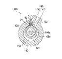
図7に示すように、本実施形態の圧縮機101は、シャフト108および圧縮機構110の構成が上記第1実施形態と異なっている。また、本実施形態の圧縮機101では、2本の吸入管3が、密閉ケーシング2の側部に上下に並んで設けられている。その他の構成は上記第1実施形態と同様であるため、同じ符号を用いて適宜その説明を省略する。
Second Embodiment
Next, a second embodiment of the present invention will be described.
The present embodiment is an example in which the present invention is applied to a two-cylinder rotary compressor.
As shown in FIG. 7, the compressor 101 of this embodiment differs in the structure of the shaft 108 and the compression mechanism 110 from the said 1st Embodiment. Further, in the compressor 101 of the present embodiment, the two suction pipes 3 are provided side by side on the side of the sealed casing 2. Since other configurations are the same as those of the first embodiment, the same reference numerals are used and the description thereof is omitted as appropriate.

シャフト108は、2つの偏心部108a、108dを有している。2つの偏心部108a、108dの軸心は、シャフト108の回転軸を中心として180°ずれている。また、シャフト108は、上記第1実施形態のシャフト8と同じく、給油路108bと、複数の排出孔108cを有している。   The shaft 108 has two eccentric portions 108a and 108d. The shaft centers of the two eccentric portions 108a and 108d are shifted by 180 ° about the rotation axis of the shaft 108. Moreover, the shaft 108 has the oil supply path 108b and the some discharge hole 108c similarly to the shaft 8 of the said 1st Embodiment.

圧縮機構110は、シャフト108の軸方向に沿って上から下に向かって順に、フロントマフラー111と、フロントヘッド120と、シリンダ130およびピストン140と、ミドルプレート150と、シリンダ160およびピストン170と、リアヘッド180と、リアマフラー112とを有する。なお、フロントヘッド120およびミドルプレート150は、ピストン140の上下端に配置されており、本発明の端板部材に相当する。また、ミドルプレート150およびリアヘッド180は、ピストン170の上下端に配置されており、本発明の端板部材に相当する。   The compression mechanism 110 includes a front muffler 111, a front head 120, a cylinder 130 and a piston 140, a middle plate 150, a cylinder 160 and a piston 170 in order from the top to the bottom along the axial direction of the shaft 108. A rear head 180 and a rear muffler 112 are provided. The front head 120 and the middle plate 150 are disposed at the upper and lower ends of the piston 140 and correspond to the end plate member of the present invention. The middle plate 150 and the rear head 180 are disposed at the upper and lower ends of the piston 170 and correspond to the end plate member of the present invention.

フロントマフラー111は、上記第1実施形態のマフラー11と同様の構成を有し、フロントヘッド120との間にマフラー空間M1を形成している。   The front muffler 111 has the same configuration as the muffler 11 of the first embodiment, and forms a muffler space M1 between the front muffler 111 and the front head 120.

フロントヘッド120には、軸受け孔121と、吐出孔122(図8参照)と、油戻し孔123とが形成されている。さらに、フロントヘッド120は、上下方向に貫通する貫通孔(図示省略)が形成されている。この貫通孔は、リアヘッド180とリアマフラー112とによって形成されるマフラー空間M2内の冷媒を、マフラー空間M1に排出するための流路の一部を構成している。フロントヘッド120は、この貫通孔を有する点以外、第1実施形態のフロントヘッド20と同様の構成である。   The front head 120 has a bearing hole 121, a discharge hole 122 (see FIG. 8), and an oil return hole 123. Further, the front head 120 has a through hole (not shown) penetrating in the vertical direction. The through hole constitutes a part of a flow path for discharging the refrigerant in the muffler space M2 formed by the rear head 180 and the rear muffler 112 to the muffler space M1. The front head 120 has the same configuration as the front head 20 of the first embodiment, except that the front head 120 has the through hole.

図8に示すように、シリンダ130には、圧縮室131と、吸入孔132と、ブレード収容部133とが形成されている。さらに、シリンダ130には、圧縮室131の外周側部分に、後述するマフラー空間M2内の冷媒をマフラー空間M1に排出するための貫通孔135が形成されている。シリンダ130は、この貫通孔135を有する点以外、第1実施形態のシリンダ30と同様の構成である。   As shown in FIG. 8, the cylinder 130 is formed with a compression chamber 131, a suction hole 132, and a blade accommodating portion 133. Further, a through hole 135 for discharging a refrigerant in the muffler space M2 described later to the muffler space M1 is formed in the outer peripheral side portion of the compression chamber 131 in the cylinder 130. The cylinder 130 has the same configuration as the cylinder 30 of the first embodiment except that the cylinder 130 has the through hole 135.

ピストン140は、上記第1実施形態のピストン40と同様の構成であって、ローラ41と、ブレード42とから構成されている。ローラ41は、偏心部108aの外周面に回転可能に装着されており、ブレード42は、シリンダ130のブレード収容部133に配置された一対のブッシュ34の間に進退可能に配置されている。また、ピストン140は、上記第1実施形態のピストン40と同じく、金属材料からなる基材43と、基材43よりも熱伝導率の小さいコーティング層44a、および、基材43よりも熱伝導率の大きいコーティング層44bとから構成されている。コーティング層44aは、ピストン40の外周面において、径方向隙間dが最も小さくなる位置にピストン140がある際に、高圧室31bを画定する部分に設けられている。コーティング層44bは、ローラ41の外周面において、径方向隙間dが最も小さくなる位置にピストン140がある際に、低圧室31aを画定する部分に設けられている。   The piston 140 has the same configuration as the piston 40 of the first embodiment, and includes a roller 41 and a blade 42. The roller 41 is rotatably mounted on the outer peripheral surface of the eccentric portion 108 a, and the blade 42 is disposed between the pair of bushes 34 disposed in the blade accommodating portion 133 of the cylinder 130 so as to advance and retreat. Further, the piston 140 is similar to the piston 40 of the first embodiment, the base material 43 made of a metal material, the coating layer 44 a having a lower thermal conductivity than the base material 43, and the thermal conductivity of the base material 43. And a large coating layer 44b. The coating layer 44a is provided on the outer peripheral surface of the piston 40 at a portion that defines the high-pressure chamber 31b when the piston 140 is at a position where the radial gap d is the smallest. The coating layer 44b is provided on the outer peripheral surface of the roller 41 at a portion that defines the low pressure chamber 31a when the piston 140 is located at a position where the radial gap d is the smallest.

ミドルプレート150は、円環状の板部材であって、シリンダ130とシリンダ160との間に配置され、シリンダ130の圧縮室131の下端を閉塞すると共に、シリンダ160の圧縮室131の上端を閉塞している。また、ミドルプレート150には、後述するマフラー空間M2内の冷媒をマフラー空間M1に排出するための貫通孔(図示省略)が形成されている。ミドルプレート150は、金属材料で形成されている。   The middle plate 150 is an annular plate member that is disposed between the cylinder 130 and the cylinder 160 and closes the lower end of the compression chamber 131 of the cylinder 130 and closes the upper end of the compression chamber 131 of the cylinder 160. ing. Further, the middle plate 150 is formed with a through hole (not shown) for discharging a refrigerant in the muffler space M2 described later to the muffler space M1. The middle plate 150 is made of a metal material.

シリンダ160は、上述したシリンダ130と同様の構成であって、圧縮室161と、吸入孔162と、一対のブッシュ34が配置されたブレード収容部(図示省略)と、貫通孔(図示省略)とを有する。   The cylinder 160 has the same configuration as the cylinder 130 described above, and includes a compression chamber 161, a suction hole 162, a blade accommodating portion (not shown) in which a pair of bushes 34 are arranged, and a through hole (not shown). Have

ピストン170は、上記第1実施形態のピストン40と同様の構成であって、ローラ41と、ブレード42とから構成されている。ローラ41は、偏心部108dの外周面に回転可能に装着されており、ブレード42は、シリンダ160のブレード収容部(図示省略)に配置された一対のブッシュ34の間に進退可能に配置されている。また、ピストン170は、上記第1実施形態のピストン40と同じく、金属材料からなる基材43と、基材43よりも熱伝導率の小さいコーティング層44a、および、基材43よりも熱伝導率の大きいコーティング層44bとから構成されている。コーティング層44aは、ピストン40の外周面において、径方向隙間dが最も小さくなる位置にピストン170がある際に、高圧室31bを画定する部分に設けられている。コーティング層44bは、ローラ41の外周面において、径方向隙間dが最も小さくなる位置にピストン170がある際に、低圧室31aを画定する部分に設けられている。   The piston 170 has the same configuration as the piston 40 of the first embodiment, and includes a roller 41 and a blade 42. The roller 41 is rotatably mounted on the outer peripheral surface of the eccentric portion 108d, and the blade 42 is disposed between a pair of bushes 34 disposed in a blade accommodating portion (not shown) of the cylinder 160 so as to be able to advance and retreat. Yes. The piston 170 has a base material 43 made of a metal material, a coating layer 44a having a lower thermal conductivity than the base material 43, and a thermal conductivity higher than that of the base material 43, like the piston 40 of the first embodiment. And a large coating layer 44b. The coating layer 44a is provided on the outer peripheral surface of the piston 40 at a portion that defines the high pressure chamber 31b when the piston 170 is located at a position where the radial gap d is the smallest. The coating layer 44b is provided on the outer peripheral surface of the roller 41 at a portion that defines the low-pressure chamber 31a when the piston 170 is at a position where the radial gap d is the smallest.

リアヘッド180は、シリンダ160の下側に配置され、シリンダ160の圧縮室161の下端を閉塞している。リアヘッド180は、略円環状の部材であって、その中央部に、シャフト108が回転可能に挿通される軸受け孔181が形成されている。また、リアヘッド180には、シリンダ160の圧縮室161において圧縮された冷媒を、リアヘッド180とリアマフラー112との間に形成されるマフラー空間M2に吐出するための吐出孔(図示省略)が形成されている。さらに、リアヘッド180には、マフラー空間M2内の冷媒をマフラー空間M1に排出するための貫通孔(図示省略)が形成されている。また、リアヘッド180の下面には、圧縮室131内の圧力に応じて吐出孔を開閉する弁機構(図示省略)が取り付けられている。リアヘッド180は、金属材料で形成されている。   The rear head 180 is disposed below the cylinder 160 and closes the lower end of the compression chamber 161 of the cylinder 160. The rear head 180 is a substantially annular member, and a bearing hole 181 through which the shaft 108 is rotatably inserted is formed at the center thereof. Further, the rear head 180 is formed with a discharge hole (not shown) for discharging the refrigerant compressed in the compression chamber 161 of the cylinder 160 to the muffler space M2 formed between the rear head 180 and the rear muffler 112. Yes. Further, the rear head 180 is formed with a through hole (not shown) for discharging the refrigerant in the muffler space M2 to the muffler space M1. A valve mechanism (not shown) that opens and closes the discharge hole according to the pressure in the compression chamber 131 is attached to the lower surface of the rear head 180. The rear head 180 is made of a metal material.

リアマフラー112は、リアヘッド180の吐出孔(図示省略)から冷媒が吐出される際の騒音を低減するために設けられている。リアマフラー112は、リアヘッド180の下面にボルトによって取り付けられ、リアヘッド180との間にマフラー空間M2を形成している。マフラー空間M2は、リアヘッド180、シリンダ160、ミドルプレート150、シリンダ130およびフロントヘッド120にそれぞれ形成された貫通孔を介して、マフラー空間M1と連通している。   The rear muffler 112 is provided to reduce noise when the refrigerant is discharged from the discharge hole (not shown) of the rear head 180. The rear muffler 112 is attached to the lower surface of the rear head 180 with bolts, and forms a muffler space M2 between the rear muffler 112 and the rear head 180. The muffler space M2 communicates with the muffler space M1 through through holes formed in the rear head 180, the cylinder 160, the middle plate 150, the cylinder 130, and the front head 120, respectively.

本実施形態の圧縮機101の動作について説明する。
吸入孔132、162から圧縮室131、161に冷媒を供給しつつ、モータ7の駆動によりシャフト108を回転させると、偏心部108aに装着されたピストン140のローラ41は圧縮室131の周壁面に沿って移動する。これにより、圧縮室131内で冷媒が圧縮される。これと並行して、偏心部108dに装着されたピストン170のローラ41は圧縮室161の周壁面に沿って移動する。これにより、圧縮室161内で冷媒が圧縮される。
The operation of the compressor 101 of this embodiment will be described.
When the shaft 108 is rotated by driving the motor 7 while supplying the refrigerant from the suction holes 132 and 162 to the compression chambers 131 and 161, the roller 41 of the piston 140 attached to the eccentric portion 108 a is placed on the peripheral wall surface of the compression chamber 131. Move along. Thereby, the refrigerant is compressed in the compression chamber 131. In parallel with this, the roller 41 of the piston 170 attached to the eccentric portion 108 d moves along the peripheral wall surface of the compression chamber 161. As a result, the refrigerant is compressed in the compression chamber 161.

圧縮室131内の圧力が所定の圧力以上になった時点で、フロントヘッド120に設けられた弁機構が開弁して、圧縮室131内の冷媒がフロントヘッド120の吐出孔22からマフラー空間M1に吐出される。また、圧縮室161内の圧力が所定の圧力以上になった時点で、リアヘッド180に設けられた弁機構が開弁して、圧縮室161内の冷媒がリアヘッド180の吐出孔(図示省略)からマフラー空間M2に吐出される。マフラー空間M2に吐出された冷媒は、リアヘッド180、シリンダ160、ミドルプレート150、シリンダ130およびフロントヘッド120にそれぞれ形成された貫通孔を介して、マフラー空間M1に吐出される。   When the pressure in the compression chamber 131 becomes equal to or higher than a predetermined pressure, the valve mechanism provided in the front head 120 is opened, and the refrigerant in the compression chamber 131 flows from the discharge hole 22 of the front head 120 through the muffler space M1. Discharged. Further, when the pressure in the compression chamber 161 becomes equal to or higher than a predetermined pressure, the valve mechanism provided in the rear head 180 is opened, and the refrigerant in the compression chamber 161 is discharged from a discharge hole (not shown) of the rear head 180. It is discharged into the muffler space M2. The refrigerant discharged to the muffler space M2 is discharged to the muffler space M1 through through holes formed in the rear head 180, the cylinder 160, the middle plate 150, the cylinder 130, and the front head 120, respectively.

マフラー空間M1に吐出された冷媒は、フロントマフラー111のマフラー吐出孔(図示省略)から圧縮機構110の外に吐出されて、その後、固定子7bと回転子7aとの間のエアギャップを通過した後、最終的に、排出管4から密閉ケーシング2の外に排出される。   The refrigerant discharged into the muffler space M1 is discharged out of the compression mechanism 110 through a muffler discharge hole (not shown) of the front muffler 111, and then passes through an air gap between the stator 7b and the rotor 7a. Thereafter, it is finally discharged from the discharge pipe 4 to the outside of the sealed casing 2.

本実施形態では、上記第1実施形態と同じく、ピストン140、170の外周面において、径方向隙間dが最も小さくなる位置にピストン140、170がある際に、高圧室31bを画定する部分に断熱領域が設けられており、ピストン140、170のローラ41の外周面において、径方向隙間dが最も小さくなる位置にピストン140、170がある際に、低圧室31aを画定する部分に放熱領域が設けられているので、上記第1実施形態と同様の効果が得られる。   In the present embodiment, as in the first embodiment, when the pistons 140 and 170 are located on the outer peripheral surfaces of the pistons 140 and 170 at the position where the radial gap d is the smallest, heat insulation is provided at a portion defining the high-pressure chamber 31b. When the pistons 140 and 170 are located at positions where the radial gap d is the smallest on the outer peripheral surface of the roller 41 of the pistons 140 and 170, a heat dissipation area is provided in a portion that defines the low pressure chamber 31a. Therefore, the same effect as the first embodiment can be obtained.

以上、本発明の実施形態について図面に基づいて説明したが、具体的な構成は、これらの実施形態に限定されるものでないと考えられるべきである。本発明の範囲は、上記した実施形態の説明ではなく特許請求の範囲によって示され、さらに特許請求の範囲と均等の意味および範囲内でのすべての変更が含まれる。   As mentioned above, although embodiment of this invention was described based on drawing, it should be thought that a specific structure is not limited to these embodiment. The scope of the present invention is shown not by the above description of the embodiments but by the scope of claims for patent, and further includes all modifications within the meaning and scope equivalent to the scope of claims for patent.

例えば、上述の第1実施形態では、断熱領域が、ピストン40の外周面のみに形成されている場合について説明したが、これには限定されない。図9に示すように、第1実施形態の第1変形例においては、ピストン40の外周面に形成されたコーティング層44a、44bに加えて、ピストン40の上下端面の全面に、基材43よりも熱伝導率の小さい金属材料からなるコーティング層244aが形成されている。すなわち、本変形例においては、ピストン40の上下端面にも断熱領域が設けられている。したがって、フロントヘッド20およびリアヘッド50のシリンダ30側とは反対側の熱が、フロントヘッド20やリアヘッド50を介してピストン40に伝わるのを防ぐことができる。なお、上述の第2実施形態においても、この変形例を適用することができる。   For example, in the above-described first embodiment, the case where the heat insulating region is formed only on the outer peripheral surface of the piston 40 has been described, but the present invention is not limited to this. As shown in FIG. 9, in the first modification of the first embodiment, in addition to the coating layers 44 a and 44 b formed on the outer peripheral surface of the piston 40, A coating layer 244a made of a metal material having a low thermal conductivity is also formed. That is, in the present modification, the heat insulating regions are also provided on the upper and lower end surfaces of the piston 40. Therefore, heat on the opposite side of the front head 20 and the rear head 50 to the cylinder 30 side can be prevented from being transmitted to the piston 40 via the front head 20 and the rear head 50. Note that this modification can also be applied to the second embodiment described above.

また、上述の第1実施形態では、基材43よりも熱伝導率の大きいコーティング層44bを形成することで放熱領域を設けている場合について説明したが、これには限定されない。図10に示すように、第1実施形態の第2変形例においては、コーティング層44bを設ける代わりに、凹部344が形成されている。凹部344は、ローラ41の外周面において、圧縮室31の軸中心からローラ41の軸中心側に向かって延在する直線Lが吸入孔32におけるローラ41の移動方向下流側の端部を通る際に、低圧室31aを画定する部分に形成されている。本変形例においては、凹部344は、上下方向に延びる溝状であり3つ形成されているが、凹部の形状およびその個数は適宜変更可能である。また、凹部344の代わりに凸部を形成してもよい。なお、凸部を形成する場合には、ローラ41の外周面と圧縮室31の周壁面との接触と避けるために、ピストン40が移動する際にローラ41の外周面において吸入孔32と対向する部分に凸部を形成する、圧縮室31の周壁面に凸部を受け入れる凹部を形成するなどする必要がある。さらに、コーティング層44bを形成すると共に凹部や凸部を形成するようにしてもよい。本変形例では、凹部344によりローラ41の外周面の表面積を増加させることで、ピストン40に与えられた熱を確実に放熱できる。なお、上述の第2実施形態においても、この変形例を適用することができる。   Moreover, although the above-mentioned 1st Embodiment demonstrated the case where the thermal radiation area | region was provided by forming the coating layer 44b with larger heat conductivity than the base material 43, it is not limited to this. As shown in FIG. 10, in the second modification of the first embodiment, a recess 344 is formed instead of providing the coating layer 44b. The concave portion 344 is formed when a straight line L extending from the axial center of the compression chamber 31 toward the axial center of the roller 41 passes through the end of the suction hole 32 on the downstream side in the moving direction of the roller 41 on the outer peripheral surface of the roller 41. In addition, it is formed in a portion that defines the low pressure chamber 31a. In this modification, the recess 344 has a groove shape extending in the vertical direction and is formed in three, but the shape and the number of the recesses can be appropriately changed. A convex portion may be formed instead of the concave portion 344. When the convex portion is formed, the outer surface of the roller 41 faces the suction hole 32 when the piston 40 moves in order to avoid contact with the outer surface of the roller 41 and the peripheral wall surface of the compression chamber 31. It is necessary to form a convex part in the part, or to form a concave part that receives the convex part on the peripheral wall surface of the compression chamber 31. Further, the coating layer 44b may be formed and a concave portion or a convex portion may be formed. In this modification, the heat applied to the piston 40 can be reliably radiated by increasing the surface area of the outer peripheral surface of the roller 41 by the recess 344. Note that this modification can also be applied to the second embodiment described above.

また、基材43の外周面における放熱領域に対応する部分を覆うのは、金属製のコーティング層44bには限定されず、基材43よりも熱伝導率の大きい材料で覆われていればよい。すなわち、例えば、金属製のコーティング層44bに代えて、熱伝導率150W/mkの窒化アルミニウムなどのセラミックを用いることができる。なお、このような基材43よりも熱伝導率の大きい材料が設けられていない場合であっても、基材43の表面が断熱材料で覆われておらず、基材43の表面が露出した状態であれば、そこからピストン40に与えられた熱を放熱できる。   Further, covering the portion corresponding to the heat radiation area on the outer peripheral surface of the base material 43 is not limited to the metal coating layer 44 b, and may be covered with a material having a higher thermal conductivity than the base material 43. . That is, for example, a ceramic such as aluminum nitride having a thermal conductivity of 150 W / mk can be used instead of the metal coating layer 44b. Even when such a material having a higher thermal conductivity than the base material 43 is not provided, the surface of the base material 43 is not covered with the heat insulating material, and the surface of the base material 43 is exposed. If it is in a state, the heat given to the piston 40 from there can be radiated.

加えて、上述の第1実施形態では、ローラ41の外周形状が円形である場合について説明したが、図11に示すように、第1実施形態の第3変形例のピストン440では、ローラ441の外周面に、ブレード442の基端部から吸入孔32側(図11中の右側)に延在する切欠きが形成されていている。本変形例においては、断熱領域が設けられていない領域(非断熱領域)が、圧縮室31の軸中心からローラ441の軸中心側に向かって延在する直線Lが、吸入孔32におけるローラ441の移動方向(図11中の時計回り)の下流側の端部を通る時に、ローラ441の外周面のうちで低圧室31aを画定する部分(図中太線で示す部分)を含む領域に形成されていれば、第1実施形態と同様に、比較的低温の冷媒によりピストン440に与えられた熱を効率よく放熱できるという効果を得ることができる。   In addition, in the first embodiment described above, the case where the outer peripheral shape of the roller 41 is circular has been described. However, in the piston 440 of the third modification example of the first embodiment, as shown in FIG. A notch extending from the base end portion of the blade 442 to the suction hole 32 side (right side in FIG. 11) is formed on the outer peripheral surface. In this modification, a straight line L extending from the axial center of the compression chamber 31 toward the axial center side of the roller 441 is an area where the heat insulating area is not provided (non-insulated area). Is formed in a region including a portion (a portion indicated by a bold line in the figure) that delimits the low-pressure chamber 31a on the outer peripheral surface of the roller 441 when passing through the downstream end of the moving direction (clockwise in FIG. 11). If so, the effect that the heat given to the piston 440 by the relatively low-temperature refrigerant can be efficiently dissipated can be obtained as in the first embodiment.

さらに、上述の第1および第2実施形態では、基材43よりも熱伝導率の小さい金属製のコーティング層44aを形成することで断熱領域を設けている場合について説明したが、これには限定されない。基材43の外周面における断熱領域に対応する部分を覆うのは、金属製のコーティング層44aには限定されず、基材43よりも熱伝導率の小さい材料で覆われていればよい。すなわち、例えば、金属製のコーティング層44aに代えて、熱伝導率0.25W/mkのPTFE(ポリテトラフルオロエチレン)などの樹脂材料や、熱伝導率3W/mkのジルコニアなどのセラミックを用いることができる。   Further, in the first and second embodiments described above, the case where the heat insulating region is provided by forming the metal coating layer 44a having a thermal conductivity smaller than that of the base material 43 has been described. Not. The portion corresponding to the heat insulating region on the outer peripheral surface of the base material 43 is not limited to the metal coating layer 44 a, and may be covered with a material having a lower thermal conductivity than the base material 43. That is, for example, instead of the metal coating layer 44a, a resin material such as PTFE (polytetrafluoroethylene) having a thermal conductivity of 0.25 W / mk or a ceramic such as zirconia having a thermal conductivity of 3 W / mk is used. Can do.

加えて、上述の第1および第2実施形態では、断熱領域は、ピストン40の外周面において、径方向隙間dが最も小さくなる位置にピストン40がある際に、高圧室31bを画定する部分に設けられている場合について説明したが、断熱領域は、この実施形態で設けられている部分の少なくとも一部を含む領域に形成されていれば良い。   In addition, in the first and second embodiments described above, the heat insulating region is a portion that defines the high pressure chamber 31b when the piston 40 is located at the position where the radial gap d is the smallest on the outer peripheral surface of the piston 40. Although the case where it was provided was demonstrated, the heat insulation area | region should just be formed in the area | region containing at least one part of the part provided in this embodiment.

さらに、上述の第1および第2実施形態では、放熱領域は、ローラ41の外周面において、径方向隙間dが最も小さくなる位置にピストン40がある際に、低圧室31aを画定する部分に設けられている場合について説明したが、これには限定されない。放熱領域は、ピストン40の外周面において、断熱領域が設けられていない領域の少なくとも一部に設けられていれば良い。   Furthermore, in the above-described first and second embodiments, the heat radiation area is provided in a portion defining the low pressure chamber 31a when the piston 40 is located at the position where the radial gap d is the smallest on the outer peripheral surface of the roller 41. However, the present invention is not limited to this. The heat radiating region may be provided in at least a part of the region where the heat insulating region is not provided on the outer peripheral surface of the piston 40.

また、上述の第1および第2実施形態では、圧縮機構は、フロントヘッド20、120の外周部が密閉ケーシング2の内周面に固定されることで支持されているが、シリンダ30、130、160、ミドルプレート150、またはリアヘッド50、180の外周部が密閉ケーシング2の内周面に固定されることで支持される構成であってもよい。   In the first and second embodiments described above, the compression mechanism is supported by the outer peripheral portion of the front heads 20 and 120 being fixed to the inner peripheral surface of the sealed casing 2, but the cylinders 30, 130, The outer peripheral part of 160, the middle plate 150, or the rear heads 50 and 180 may be supported by being fixed to the inner peripheral surface of the sealed casing 2.

本発明を利用すれば、ピストンの熱膨張を確実に抑制できる。   By utilizing the present invention, the thermal expansion of the piston can be reliably suppressed.

1 圧縮機
20、120 フロントヘッド(端板部材)
30、130、160 シリンダ
31、131、161 圧縮室
31a 低圧室
31b 高圧室
32、132、162 吸入孔
32a 吸入口
33、133 ブレード収容部
40、140、170 ピストン
41 ローラ
42 ブレード
43 基材
44a、44b、244a コーティング層
50、180 リアヘッド(端板部材)
344 凹部
1 Compressor 20, 120 Front head (end plate member)
30, 130, 160 Cylinder 31, 131, 161 Compression chamber 31a Low pressure chamber 31b High pressure chamber 32, 132, 162 Suction hole 32a Suction port 33, 133 Blade accommodating portion 40, 140, 170 Piston 41 Roller 42 Blade 43 Base material 44a, 44b, 244a Coating layer 50, 180 Rear head (end plate member)
344 recess

Claims (6)

圧縮室および前記圧縮室に連通したブレード収容部を有するシリンダと、
前記シリンダの軸方向両端にそれぞれ配置される端板部材と、
前記圧縮室に配置された環状のローラ、および前記ローラの外周面から延在し且つ前記ブレード収容部に対して進退可能に配置されたブレードを有するピストンとを備え、
前記ピストンは、前記ローラが前記圧縮室の周壁面に沿って移動しつつ前記ブレードと共に前記圧縮室を高圧室と低圧室とに区画するものであって、
前記ピストンの外周面は、
前記ピストンの基材よりも熱伝導率の小さい断熱材料が設けられた断熱領域と、
前記断熱材料が設けられていない非断熱領域とを有しており、
前記断熱領域は、前記ピストンの外周面において、少なくとも、前記ローラの外周面と前記圧縮室の内周面との間のすき間が最も小さくなる位置に前記ピストンがある際に、前記高圧室を画定する部分の一部を含む領域に形成されていることを特徴とする圧縮機。
A cylinder having a compression chamber and a blade accommodating portion communicating with the compression chamber;
End plate members respectively disposed at both axial ends of the cylinder;
An annular roller disposed in the compression chamber, and a piston having a blade extending from the outer peripheral surface of the roller and disposed so as to be capable of moving back and forth with respect to the blade accommodating portion,
The piston divides the compression chamber into a high pressure chamber and a low pressure chamber together with the blade while the roller moves along the peripheral wall surface of the compression chamber,
The outer peripheral surface of the piston is
A heat insulating region provided with a heat insulating material having a lower thermal conductivity than the base material of the piston;
And has a non-insulating region in which the heat insulating material is not provided,
The heat insulation region defines the high pressure chamber when the piston is at a position where the clearance between the outer peripheral surface of the roller and the inner peripheral surface of the compression chamber is at a minimum on the outer peripheral surface of the piston. A compressor characterized in that the compressor is formed in a region including a part of the portion to be performed.
前記断熱領域は、前記ローラの外周面において、前記ブレードとの境界部を一端とし、その境界部から高圧室側へローラ下死点に向かって延びる領域に設けられていることを特徴とする請求項1に記載の圧縮機。   The heat insulating region is provided in a region on the outer peripheral surface of the roller, with a boundary portion with the blade as one end, and extending from the boundary portion toward the high pressure chamber side toward the roller bottom dead center. Item 2. The compressor according to Item 1. 前記シリンダは、前記圧縮室の周壁面に開口し且つ前記圧縮室に冷媒を導入するための吸入孔をさらに有し、
前記非断熱領域は、少なくとも、前記ローラの外周面において、前記圧縮室の軸方向から視て前記圧縮室の軸中心から前記ローラの軸中心側に向かって延在する直線が前記吸入孔における前記ローラの移動方向下流側の端部を通る際に、前記低圧室を画定する部分を含む領域に形成されていることを特徴とする請求項1または2に記載の圧縮機。
The cylinder further has a suction hole that opens to a peripheral wall surface of the compression chamber and introduces a refrigerant into the compression chamber;
The non-insulating region has a straight line extending from the axial center of the compression chamber toward the axial center side of the roller when viewed from the axial direction of the compression chamber at least on the outer peripheral surface of the roller. 3. The compressor according to claim 1, wherein the compressor is formed in a region including a portion that defines the low-pressure chamber when passing through an end portion on the downstream side in the moving direction of the roller.
前記非断熱領域の少なくとも一部には、前記ピストンの基材よりも熱伝導率の大きい放熱材料が設けられていることを特徴とする請求項1〜3のいずれか1項に記載の圧縮機。   The compressor according to any one of claims 1 to 3, wherein a heat radiating material having a thermal conductivity larger than that of the base material of the piston is provided in at least a part of the non-insulating region. . 前記非断熱領域は、前記ローラの外周面において、前記圧縮室の軸方向から視て前記圧縮室の軸中心から前記ローラの軸中心側に向かって延在する直線が前記吸入孔における前記ローラの移動方向下流側の端部を通る際に、前記低圧室を画定する部分に形成された凹部および凸部の少なくともいずれか一方を有していることを特徴とする請求項1〜4のいずれか1項に記載の圧縮機。   The non-adiabatic region has a straight line extending from the axial center of the compression chamber toward the axial center of the roller when viewed from the axial direction of the compression chamber on the outer peripheral surface of the roller. 5. It has at least any one of the recessed part and convex part which were formed in the part which demarcates the said low-pressure chamber when passing the edge part of a movement direction downstream side, The any one of Claims 1-4 characterized by the above-mentioned. The compressor according to item 1. 前記ピストンの軸方向端面は、前記ピストンの基材よりも熱伝導率の小さい断熱材料が設けられた断熱領域を有していることを特徴とする請求項1〜5のいずれか1項に記載の圧縮機。   The axial end surface of the piston has a heat insulating region provided with a heat insulating material having a thermal conductivity smaller than that of the base material of the piston. Compressor.
JP2010266856A 2010-11-30 2010-11-30 Compressor Pending JP2012117425A (en)

Priority Applications (1)

Application Number Priority Date Filing Date Title
JP2010266856A JP2012117425A (en) 2010-11-30 2010-11-30 Compressor

Applications Claiming Priority (1)

Application Number Priority Date Filing Date Title
JP2010266856A JP2012117425A (en) 2010-11-30 2010-11-30 Compressor

Publications (1)

Publication Number Publication Date
JP2012117425A true JP2012117425A (en) 2012-06-21

Family

ID=46500563

Family Applications (1)

Application Number Title Priority Date Filing Date
JP2010266856A Pending JP2012117425A (en) 2010-11-30 2010-11-30 Compressor

Country Status (1)

Country Link
JP (1) JP2012117425A (en)

Cited By (2)

* Cited by examiner, † Cited by third party
Publication number Priority date Publication date Assignee Title
CN103032331A (en) * 2013-01-16 2013-04-10 东莞市金瑞五金制品有限公司 Compressor and application thereof
CN113623213A (en) * 2021-09-22 2021-11-09 广东美芝制冷设备有限公司 Piston, compression assembly and rotary compressor

Similar Documents

Publication Publication Date Title
JP4077029B2 (en) Expander and expander integrated compressor
JP2013238132A (en) Compressor
JP6548915B2 (en) Compressor
JP2012117425A (en) Compressor
JP2012117426A (en) Compressor
JP2010025103A (en) Rotary compressor
JP2010255594A (en) Rotary compressor
JP2012137009A (en) Compressor
JP5041059B2 (en) Compressor
JP2012137013A (en) Compressor
JPWO2018142505A1 (en) Compressor
JP2016037906A (en) High-pressure doom type compressor
JP5041057B2 (en) Compressor
JP2005188407A (en) Heat insulation structure in piston type compressor
JP2006207391A (en) Fluid machine
JP2014092044A (en) Compressor
JP5920406B2 (en) Compressor
JP2016037907A (en) High-pressure doom type compressor
JP2005076567A (en) Compressor
JP2012077636A (en) Compressor
JP4784296B2 (en) Rotary fluid machine
JP2015124756A (en) Compressor
JP2012215144A (en) Compressor
JP2014238062A (en) Rotary compressor
JP5141759B2 (en) Rotary fluid machine