JP2005291121A - Vehicle exhaust system support structure - Google Patents
Vehicle exhaust system support structure Download PDFInfo
- Publication number
- JP2005291121A JP2005291121A JP2004108738A JP2004108738A JP2005291121A JP 2005291121 A JP2005291121 A JP 2005291121A JP 2004108738 A JP2004108738 A JP 2004108738A JP 2004108738 A JP2004108738 A JP 2004108738A JP 2005291121 A JP2005291121 A JP 2005291121A
- Authority
- JP
- Japan
- Prior art keywords
- exhaust
- exhaust pipe
- silencer
- downstream
- flexible tube
- Prior art date
- Legal status (The legal status is an assumption and is not a legal conclusion. Google has not performed a legal analysis and makes no representation as to the accuracy of the status listed.)
- Granted
Links
Images
Classifications
-
- F—MECHANICAL ENGINEERING; LIGHTING; HEATING; WEAPONS; BLASTING
- F01—MACHINES OR ENGINES IN GENERAL; ENGINE PLANTS IN GENERAL; STEAM ENGINES
- F01N—GAS-FLOW SILENCERS OR EXHAUST APPARATUS FOR MACHINES OR ENGINES IN GENERAL; GAS-FLOW SILENCERS OR EXHAUST APPARATUS FOR INTERNAL-COMBUSTION ENGINES
- F01N13/00—Exhaust or silencing apparatus characterised by constructional features
- F01N13/08—Other arrangements or adaptations of exhaust conduits
-
- F—MECHANICAL ENGINEERING; LIGHTING; HEATING; WEAPONS; BLASTING
- F01—MACHINES OR ENGINES IN GENERAL; ENGINE PLANTS IN GENERAL; STEAM ENGINES
- F01N—GAS-FLOW SILENCERS OR EXHAUST APPARATUS FOR MACHINES OR ENGINES IN GENERAL; GAS-FLOW SILENCERS OR EXHAUST APPARATUS FOR INTERNAL-COMBUSTION ENGINES
- F01N13/00—Exhaust or silencing apparatus characterised by constructional features
- F01N13/18—Construction facilitating manufacture, assembly, or disassembly
- F01N13/1805—Fixing exhaust manifolds, exhaust pipes or pipe sections to each other, to engine or to vehicle body
- F01N13/1811—Fixing exhaust manifolds, exhaust pipes or pipe sections to each other, to engine or to vehicle body with means permitting relative movement, e.g. compensation of thermal expansion or vibration
- F01N13/1816—Fixing exhaust manifolds, exhaust pipes or pipe sections to each other, to engine or to vehicle body with means permitting relative movement, e.g. compensation of thermal expansion or vibration the pipe sections being joined together by flexible tubular elements only, e.g. using bellows or strip-wound pipes
Landscapes
- Engineering & Computer Science (AREA)
- Chemical & Material Sciences (AREA)
- Combustion & Propulsion (AREA)
- Mechanical Engineering (AREA)
- General Engineering & Computer Science (AREA)
- Exhaust Silencers (AREA)
- Cooling, Air Intake And Gas Exhaust, And Fuel Tank Arrangements In Propulsion Units (AREA)
Abstract
Description
本発明は、自動車などの車両のエンジンから排出される排気ガスを消音器に導き、消音後、外気に放出するようにした車両の排気系の支持構造の改良に関するものである。 The present invention relates to an improvement in a support structure for an exhaust system of a vehicle in which exhaust gas discharged from an engine of a vehicle such as an automobile is guided to a silencer and released to the outside air after being silenced.
従来、自動車などの車両において、エンジンに接続される排気系の排気管は、車体の下方を後方へと延長されて、その下流端のテールパイプは、リヤバンパーの下方に露出するように設けるのが一般的であり、たとえば、後記特許文献1(第3図参照)には、排気系のエキゾーストパイプ(テールパイプ)の排出口4にリヤパネル(リヤバンパー)1の下方を通過させて外部に露出させたものが開示されているが、このようなテールパイプの外部への露出は、車両の外観を向上させるという観点から好ましくないという問題がある。
Conventionally, in a vehicle such as an automobile, an exhaust pipe of an exhaust system connected to an engine is provided so that the lower part of the vehicle body extends rearward, and the tail pipe at the downstream end thereof is exposed below the rear bumper. For example, in Patent Document 1 (see FIG. 3) described later, the exhaust pipe (tail pipe) of the exhaust system passes through the
そこで、後記特許文献2(従来技術の項、図7参照)には、このような問題を解決する技術手段として、テールパイプ4Aの端部に連結したフィニッシャー10Aをリヤバンパー5Aの内部に配置すると共に、(排気ガスのリヤバンパー内への巻き込みを防止するために)フィニッシャー10Aの開口端をリヤバンパー5Aに形成した開口6Aまで延ばしたものが示されている。しかしながら、この特許文献2(解決課題の項参照)に述べているように、この従来技術のものは、テールパイプ4A(フィニッシャー10A)を制振する構造が採られていないため、テールパイプ4Aの振動によって、フィニッシャー10Aの開口端がリヤバンパー5Aの開口6Aの縁部と干渉しないように、開口6Aとフィニッシャー10Aの開口端との間に間隙δ1を大きく取る必要があり、外観向上を目的としてフィニッシャー10Aをリヤバンパー5Aの内部に配置したにも拘らず、間隙δ1が目立ってしまい十分な外観向上効果が得られないという、さらなる問題があった。 Therefore, in Patent Document 2 (refer to the section of the prior art, see FIG. 7), a finisher 10A connected to the end of the tail pipe 4A is disposed inside the rear bumper 5A as a technical means for solving such a problem. In addition, the opening end of the finisher 10A is extended to the opening 6A formed in the rear bumper 5A (in order to prevent the exhaust gas from getting into the rear bumper). However, as described in Patent Document 2 (refer to the section on the problem to be solved), this conventional technique does not employ a structure for damping the tail pipe 4A (finisher 10A). In order to prevent the opening end of the finisher 10A from interfering with the edge of the opening 6A of the rear bumper 5A due to vibration, it is necessary to make a large gap δ1 between the opening 6A and the opening end of the finisher 10A. In spite of the arrangement of the finisher 10A inside the rear bumper 5A, there is a further problem that the gap δ1 becomes conspicuous and a sufficient appearance improvement effect cannot be obtained.
そこで、こうした間隙δ1が目立つてしまうという、さらなる問題を解決するものとして、特許文献2(第1〜6参照)には、テールパイプ4の後端部をステイ12,13でフロアパネル14に固定することで、フィニッシャー10が揺動しないようにして間隙δ1を可及的に小さくしてもフィニッシャー10がリヤバンパー5の開口6Aの縁部に干渉しないようにし、外観向上効果が得られるようにすると共に、エンジン側から伝達される排気系の振動についてはテールパイプ5の途中に介在させたフレキシブルチューブ7で吸収させるものが開示されている。
ところで、一般にフレキシブルチューブは振動吸収性が高いという利点がある反面、振動吸収時にフレキシブルチューブで連結された上流側排気管の軸芯と、下流側排気管の軸芯とがずれることにより、それらの排気管内の有効通路面積が減少して排気抵抗が増加する要因になるという不利点があり、前記特許文献2に開示されるもの(第1〜6参照)では、テールパイプ4の途中にフレキシブルチューブ7が介在されているため、こうした排気抵抗の増加を招くという別の問題を生じる。
By the way, in general, the flexible tube has an advantage of high vibration absorption, but when the shaft core of the upstream side exhaust pipe connected by the flexible tube and the axis of the downstream side exhaust pipe are displaced at the time of absorbing the vibration, those There is a disadvantage in that the effective passage area in the exhaust pipe decreases and the exhaust resistance increases, and the one disclosed in Patent Document 2 (see first to sixth) has a flexible tube in the middle of the
本発明は、このような実情に鑑みてなされたものであり、下流側排気管と、リヤバンパーの排気管受入部との間に形成される間隙を可及的に小さくして排気系の外観向上効果を一層顕著なものとしながら排気抵抗の増加を招くことがないようにした、新規な車両の排気系支持構造を提供することを目的とするものである。 The present invention has been made in view of such a situation, and an external appearance of an exhaust system by reducing a gap formed between a downstream exhaust pipe and an exhaust pipe receiving portion of a rear bumper as much as possible. It is an object of the present invention to provide a novel vehicle exhaust system support structure that makes the improvement effect more remarkable while preventing an increase in exhaust resistance.
なお、ここで、リヤバンパーに形成される、排気管受入部とは、リヤバンパーの縦壁部に開口される通口、あるいは、その縦壁部の下側から切り欠かれる切欠き(凹部)をいう。 Here, the exhaust pipe receiving portion formed in the rear bumper is a through hole opened in the vertical wall portion of the rear bumper or a notch (recessed portion) cut out from below the vertical wall portion. Say.
前記目的を達成するため、本請求項1記載の発明は、エンジンに接続される上流側排気管の下流部を、車体に支持される消音器の排気導入口に導き、該消音器の排気流出口に連結される下流側排気管の終端部を、車体に支持されるリヤバンパーの縦壁部に形成した排気管受入部に受け入れてなる、車両の排気系において、
上流側排気管の下流部と、消音器の排気導入口とをフレキシブルチューブで連結することにより上流側排気管を消音器にフローティング支持させ、さらに、上流側排気管の下流部をフレキシブルチューブ内を通過させて前記排気導入口まで延出させたことを特徴としている。
In order to achieve the above object, according to the first aspect of the present invention, the downstream portion of the upstream exhaust pipe connected to the engine is led to the exhaust inlet of the silencer supported by the vehicle body, and the exhaust flow of the silencer is In the exhaust system of the vehicle, wherein the end portion of the downstream exhaust pipe connected to the outlet is received by an exhaust pipe receiving portion formed in the vertical wall portion of the rear bumper supported by the vehicle body,
By connecting the downstream part of the upstream exhaust pipe and the exhaust inlet of the silencer with a flexible tube, the upstream exhaust pipe is floatingly supported by the silencer, and the downstream part of the upstream exhaust pipe is moved inside the flexible tube. It is characterized in that it is passed through and extended to the exhaust inlet.
本請求項1記載の発明によれば、エンジンからの排気ガスを消音器へ導く上流側排気管の下流部と、消音器の排気導入口とをフレキシブルチューブで連結したので、エンジン側から伝達される排気系の振動をこのフレキシブルチューブで吸収することで、消音器の車体への支持は、車体に対して消音器を固定した状態、あるいは車体に対する消音器の変位を大幅に規制した状態にすることができる。その結果、消音器に連結される下流側排気管(テールパイプ)の車体、すなわちリヤバンパーに対する変位もきわめて小さいもとなり、リヤバンパーの縦壁部の排気管受け入れ部(開口、切欠き)と下流側排気管の終端部との間隙を小さくすることが可能になり、下流側排気管をリヤバンパーの内部に受け入れ配置することによる外観向上効果を十分に得ることができる。 According to the first aspect of the present invention, since the downstream portion of the upstream exhaust pipe that guides the exhaust gas from the engine to the silencer and the exhaust inlet of the silencer are connected by the flexible tube, it is transmitted from the engine side. By absorbing the vibration of the exhaust system with this flexible tube, the silencer support to the vehicle body is in a state where the silencer is fixed to the vehicle body or the displacement of the silencer with respect to the vehicle body is greatly regulated be able to. As a result, the displacement of the downstream exhaust pipe (tail pipe) connected to the silencer with respect to the vehicle body, that is, the rear bumper is also extremely small, and the exhaust pipe receiving portion (opening, notch) of the vertical wall portion of the rear bumper and the downstream It is possible to reduce the gap with the end portion of the side exhaust pipe, and it is possible to sufficiently obtain the appearance improvement effect by receiving and arranging the downstream side exhaust pipe inside the rear bumper.
しかも、排気ガスを消音器へ導く上流側排気管の下流部をフレキシブルチューブ内を通過させて消音器の排気導入口まで延出させたので、フレキシブルチューブによって、排気系を流れる排気ガスの排気抵抗が増加することもない。 In addition, since the downstream part of the upstream exhaust pipe that leads the exhaust gas to the silencer is passed through the flexible tube and extended to the exhaust inlet of the silencer, the exhaust resistance of the exhaust gas flowing through the exhaust system by the flexible tube Will not increase.
以下、本発明の実施の形態を、添付図面に例示した本発明の実施例に基づいて以下に具体的に説明する。 DESCRIPTION OF THE PREFERRED EMBODIMENTS Embodiments of the present invention will be specifically described below based on examples of the present invention illustrated in the accompanying drawings.
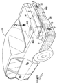
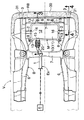
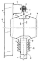
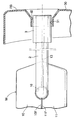
まず、図1〜4を参照して本発明の第1実施例について説明するに、図1は、本発明排気系支持構造を備えた乗用自動車の後部斜視図、図2は、図1の2矢視の車両後部の横断平面図、図3は、図2の3−3線に沿う拡大断面図、図4は、図2の4−4線に沿う拡大断面図である。 First, the first embodiment of the present invention will be described with reference to FIGS. 1 to 4. FIG. 1 is a rear perspective view of a passenger car equipped with the exhaust system support structure of the present invention, and FIG. FIG. 3 is an enlarged cross-sectional view taken along the line 3-3 in FIG. 2, and FIG. 4 is an enlarged cross-sectional view taken along the line 4-4 in FIG.
図1,2において、乗用自動車VのエンジンEの排気系Exは、エンジンEの排気マニホールドに接続される上流側排気管1と、この上流側排気管1を流れる排気ガスを導入してその排気音を消音する消音器Mと、消音器M内の消音後の排気ガスを外気に排出する2本の下流側排気管2,2とを備える。
1 and 2, the exhaust system Ex of the engine E of the passenger car V introduces an
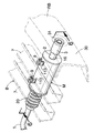
前記上流側排気管1は、その上流部が車体前部に搭載されるエンジンEの排気マニホールドに連通接続されて車体の前後方向後方へと延びており、その下流部は、消音器Mの排気導入口15に環状の間隙d1を存して延出されており、その下流端は、消音器M内にまで及んでいる(図3参照)。
The
前記消音器Mは、上部半体10のフランジ部10Fと、下部半体11のフランジ部11F同士を一体に合掌結合して、横長の密閉箱状に形成され、その内部に排気膨張室12が画成されている。この消音器Mは車体Bの後方中央部に着脱可能に支持されており、すなわち、消音器Mの周囲には、複数の取付舌片13…が一体に張り出しており、これらの取付舌片13…が車体Bのサイドフレーム6およびクロスメンバー7にボルト・ナット8により弾性グロメット9を介して着脱可能に弾性支持される。
The silencer M is formed as a horizontally-enclosed box by integrally joining the
図2,3に示すように、消音器Mの前壁には、その左右方向の一側に偏して排気導入口15が車体の前方に向けた開口されている。この排気導入口15には、前述のように、上流側排気管1の下流部が環状の間隙d1を存して延出されており、その下流部の開口端は、排気導入口15に近い排気膨張室12内に及んでいる。上流側排気管1の下流部と、排気導入口15とは、それらを覆う耐熱性のフレキシブルチューブ20により気密に連結される。フレキシブルチューブ20の一端は、上流側排気管1の下流部の外周面に気密に固定され、また、その他端は、消音器Mの排気導入口15の外周面に気密に固定される。これにより、上流側排気管1の下流部はフレキシブルチューブ20により消音器Mに揺動支持(フローティング支持)されることになり、エンジンE側から伝達される排気系の振動を、このフレキシブルチューブ20により効果的に吸収することができる。
As shown in FIGS. 2 and 3, an
また、図3に示すように、上流側排気管1の下流部は、フレキシブルチューブ20および排気導入口15に接触することなくそれらの内部を通過し、上流排気管1と消音器Mとの間に相対的な変位があっても上流側排気管1内を流れる排気ガスの流れ抵抗が増すことがない。
Further, as shown in FIG. 3, the downstream portion of the upstream
図2,4に示すように、消音器Mの左右両側には、対をなす左右排気流出口16,16が対称的に開口されており、これらの排気流出口16,16には、下流側排気管(テールパイプ)2,2の上流端がそれぞれ気密に固定連結されている。各下流側排気管2,2はエルボ状に屈曲されていて、車体Bの左右方向に延長されたのち、屈曲されてその後方に延長されており、その終端部に、この下流側排気管2,2の外観を向上さるためのフィニッシャー3,3が固定されている。
2 and 4, a pair of left and
図1,4に示すように、乗用自動車VのリヤバンパーRBの縦壁部30の左右には、排気管受入部としての通口31,31が対称的に形成される。これらの通口31,31は、リヤバンパーRBの縦壁部30の前後面にそれぞれ開放されていて、それらの通口31,31の後半部は末広状に拡開されている。図4に明瞭に示すように、各下流側排気管2,2のフィニッシャー3,3は、前記通口31,31内に受け入れられており、このフィニッシャー3,3の外端面は、通口31,31の後面よりも内方にあり、リヤバンパーRBの外面より突出することがない。また、フィニッシャー3,3の外周面と通口31,31との間には、環状の間隙d2、d2が形成され、それら同士が接触しないようにしてある。
As shown in FIGS. 1 and 4, on the left and right sides of the
つぎに、この実施例の作用について説明する。 Next, the operation of this embodiment will be described.
いま、エンジンEが運転されると、排気ガスは、エンジンEの排気ポートより排気マニホールドを通って上流側排気管1へと流れ、そこから消音器Mへと導かれる。消音器M内の排気膨張室12に流入した排気ガスは、ここで膨張消音されたのち、2本の下流側排気管(テールパイプ)2,2、それらの終端部のフィニッシャー3,3を経て外気に排出される。
Now, when the engine E is operated, the exhaust gas flows from the exhaust port of the engine E to the
ところで、上流側排出管1は、フレキシブルチューブ20により消音器Mにフローティング支持されるので、エンジンEより上流側排気管1に伝達される振動をこのフレキシブルチューブ20によって吸収することができ、消音器Mの車体Bへの支持は、車体Bに対して消音器Mを固定した状態、あるいは、車体Bに対する消音器Mの変位を大幅に規制した状態にすることができる。その結果、消音器Mに連結される下流側排気管(テールパイプ)2の車体B、すなわちリヤバンパーRBに対する変位もきわめて小さいものとなり、リヤバンパーRBの縦壁部30の通口31,31と下流側排気管2,2との間隙d2,d2を小さくすることが可能となり、下流側排気管2,2をリヤバンパーRBの内部に配置することによる外観向上を顕著に高めることができる。
By the way, since the
しかも、排気ガスを消音器Mへ導く上流側排気管1をフレキシブルチューブ20内を通過させて消音器Mの排気導入口15まで延出させたので、上流側排気管1をフレキシブルチューブ20を介して消音器Mに接続したにも拘らず排気系を流れる排気ガスの排気抵抗が増大することがない。
In addition, since the
つぎに、図5,6を参照して、本発明の第2実施例について説明する。 Next, a second embodiment of the present invention will be described with reference to FIGS.
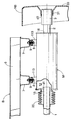
図5は、車両の排気系支持部の斜視図、図6は、図5の6−6線に沿う拡大断面図であり、図中、前記第1実施例と同じ要素には同じ符号が付される。 FIG. 5 is a perspective view of the exhaust system support portion of the vehicle, and FIG. 6 is an enlarged cross-sectional view taken along line 6-6 of FIG. 5, in which the same elements as those in the first embodiment are denoted by the same reference numerals. Is done.
この第2実施例は、消音器Mおよび下流側排気管(テールパイプ)2の構造が前記第1実施例のものと異なっており、消音器Mは車体Bの前後方向に長い密閉の中空円筒状に形成され、その内部に排気膨張室12が画成される。消音器M上面の前部および後部には、2つの取付片113,113が固定されており、これらの取付片113,113は、ボルト・ナット8,8により弾性グロメット9,9を介して車体Bのクロスメンバー7に着脱可能に固定され、これにより、消音器Mは車体Bの後部に懸吊支持される。消音器Mの前壁には、排気導入口15が開口され、上流側排気管1の下流部は環状の間隙d1を存して排気導入口15へと延出されており、その出口は、消音器Mの排気膨張室12に開口されている。排気導入口15と上流側排気管1の下流部間には、耐熱性のフレキシブルチューブ20が接続され、これにより、その下流部は、消音器Mにフレキシブルチューブ20を介してフローティング支持される。そして、上流側排気管1の下流部は、フレキシブルチューブ20内を間隙を存して通過し、消音器Mの排気導入口15へと延出されている。また、消音器Mの後壁に開口される排気流出口16には、1本の下流側排気管(テールパイプ)2が固定連結され、この下流側排気管2は、車体Bの後方へ直状に延びてその終端部にフィニッシャー3が一体に設けられる。フィニッシャー3は、前記第1実施例のものと同じくリヤバンパーRBの通口31に、間隙d2を存して受け入れられる。
In the second embodiment, the structure of the silencer M and the downstream exhaust pipe (tail pipe) 2 is different from that of the first embodiment, and the silencer M is a sealed hollow cylinder long in the front-rear direction of the vehicle body B. The
しかして、この第2実施例のものも、前記第1実施例のものと同じ作用効果を奏するものであり、下流側排気管2をリヤバンパーRBの内部に配置することによる外観向上効果を十分に発揮でき、その上、フレキシブルチューブの存在による排気抵抗の増加もない。
Therefore, the second embodiment also has the same effect as the first embodiment, and the effect of improving the appearance by arranging the
以上、本発明の実施例について説明したが、本発明はその実施例に限定されることなく、本発明の範囲内で種々の実施例が可能である。 As mentioned above, although the Example of this invention was described, this invention is not limited to the Example, A various Example is possible within the scope of the present invention.
たとえば、前記実施例では、下流側排気管(テールパイプ)は、その終端部にフィニッシャーを備えるが、このフィニッシャーはなくてもよい。また、前記実施例では、リヤバンパーの縦壁部に開口した通口に、下流側排気管の終端部を受け入れた場合を説明したが、リヤバンパーの縦壁部に、その下端から形成した切欠き(凹部)に下流側排気管の終端部を受け入れるようにしてもよく、また、前記実施例では、消音器は、1室膨張室構造としたものを採用しているが、従来公知の消音器と同様に、複膨張室構造、吸音材を内装したものなどを採用してもよい。 For example, in the above embodiment, the downstream exhaust pipe (tail pipe) includes a finisher at the end thereof, but this finisher may not be provided. In the above-described embodiment, the case where the end portion of the downstream exhaust pipe is received in the through hole opened in the vertical wall portion of the rear bumper has been described. However, a cut formed in the vertical wall portion of the rear bumper from the lower end thereof has been described. The end portion of the downstream exhaust pipe may be received in the notch (concave portion). In the embodiment, the silencer has a one-chamber expansion chamber structure. Similarly to the container, a double expansion chamber structure or a sound absorbing material may be adopted.
1・・・・・・・・・上流側排気管
2・・・・・・・・・下流側排気管(テールパイプ)
15・・・・・・・・・排気導入口
16・・・・・・・・・排気流出口
20・・・・・・・・・フレキシブルチューブ
30・・・・・・・・・縦壁部
31・・・・・・・・・排気管受入部(通口)
B・・・・・・・・・車体
E・・・・・・・・・エンジン
M・・・・・・・・・消音器
RB・・・・・・・・・リヤバンパー
1 ・ ・ ・ ・ ・ ・ ・ ・
15 ...
B ... Body E ... Engine M ... Silencer RB ... Rear bumper
Claims (1)
上流側排気管(1)の下流部と、消音器(M)の排気導入口(15)とをフレキシブルチューブ(20)で連結することにより上流側排気管(1)を消音器(M)にフローティング支持させ、さらに、上流側排気管(1)の下流部をフレキシブルチューブ(20)内を通過させて前記排気導入口(15)まで延出させたことを特徴とする、車両の排気系支持構造。
The downstream part of the upstream exhaust pipe (1) connected to the engine (E) is led to the exhaust inlet (15) of the silencer (M) supported by the vehicle body (B), and the silencer (M) An exhaust pipe receiving portion (the end portion of the downstream exhaust pipe (2) connected to the exhaust outlet (16) is formed in the vertical wall portion (30) of the rear bumper (RB) supported by the vehicle body (B) ( 31) In the vehicle exhaust system,
The upstream exhaust pipe (1) is connected to the silencer (M) by connecting the downstream portion of the upstream exhaust pipe (1) and the exhaust inlet (15) of the silencer (M) with a flexible tube (20). A vehicle exhaust system support characterized in that it is supported in a floating manner, and further, the downstream portion of the upstream exhaust pipe (1) is passed through the flexible tube (20) and extended to the exhaust inlet (15). Construction.
Priority Applications (4)
| Application Number | Priority Date | Filing Date | Title |
|---|---|---|---|
| JP2004108738A JP3944183B2 (en) | 2004-04-01 | 2004-04-01 | Vehicle exhaust system support structure |
| US11/091,726 US7458440B2 (en) | 2004-04-01 | 2005-03-28 | Vehicle exhaust system support structure |
| DE602005000366T DE602005000366T2 (en) | 2004-04-01 | 2005-04-01 | Holding arrangement for a motor vehicle exhaust system |
| EP05252089A EP1582713B1 (en) | 2004-04-01 | 2005-04-01 | Vehicle exhaust system support structure |
Applications Claiming Priority (1)
| Application Number | Priority Date | Filing Date | Title |
|---|---|---|---|
| JP2004108738A JP3944183B2 (en) | 2004-04-01 | 2004-04-01 | Vehicle exhaust system support structure |
Publications (2)
| Publication Number | Publication Date |
|---|---|
| JP2005291121A true JP2005291121A (en) | 2005-10-20 |
| JP3944183B2 JP3944183B2 (en) | 2007-07-11 |
Family
ID=34880121
Family Applications (1)
| Application Number | Title | Priority Date | Filing Date |
|---|---|---|---|
| JP2004108738A Expired - Fee Related JP3944183B2 (en) | 2004-04-01 | 2004-04-01 | Vehicle exhaust system support structure |
Country Status (4)
| Country | Link |
|---|---|
| US (1) | US7458440B2 (en) |
| EP (1) | EP1582713B1 (en) |
| JP (1) | JP3944183B2 (en) |
| DE (1) | DE602005000366T2 (en) |
Cited By (2)
| Publication number | Priority date | Publication date | Assignee | Title |
|---|---|---|---|---|
| JP2009096438A (en) * | 2007-10-19 | 2009-05-07 | Honda Motor Co Ltd | Vehicle under cover |
| JP2015013542A (en) * | 2013-07-04 | 2015-01-22 | トヨタ自動車株式会社 | Vehicle |
Families Citing this family (23)
| Publication number | Priority date | Publication date | Assignee | Title |
|---|---|---|---|---|
| DE10241883B4 (en) * | 2002-09-10 | 2012-06-21 | Andreas Stihl Ag & Co. | Hand-held implement with a mounting pin for an exhaust silencer |
| DE102006020628A1 (en) * | 2006-05-04 | 2007-11-08 | Dr.Ing.H.C. F. Porsche Ag | exhaust system |
| JP5223510B2 (en) * | 2008-07-09 | 2013-06-26 | スズキ株式会社 | Vehicle exhaust system |
| US7823938B2 (en) * | 2008-10-17 | 2010-11-02 | Honda Motor Co., Ltd. | Bumper faceplate with ports |
| US8465030B2 (en) * | 2008-12-07 | 2013-06-18 | Norduyn Inc. | Modular utility cart |
| US7686131B1 (en) * | 2008-12-16 | 2010-03-30 | Gm Global Technology Operations, Inc. | Vehicle exhaust tip assembly |
| CN102482979A (en) * | 2009-06-23 | 2012-05-30 | 海因里希.吉勒特有限责任公司 | Tubular acoustic insulating element |
| JP5299635B2 (en) * | 2009-08-26 | 2013-09-25 | スズキ株式会社 | Exhaust pipe support structure |
| DE102010020033A1 (en) * | 2010-05-11 | 2011-11-17 | J. Eberspächer GmbH & Co. KG | Exhaust system and associated support structure |
| US8047328B1 (en) * | 2010-06-09 | 2011-11-01 | Mark Milewicz | Plastic muffler and method for making same |
| CN102294954A (en) * | 2010-06-28 | 2011-12-28 | 北汽福田汽车股份有限公司 | Automobile |
| DE102010041666A1 (en) * | 2010-09-29 | 2012-05-03 | Röchling Automotive AG & Co. KG | Exhaust gas guiding device for passenger car, has spring element provided such that radial movement of gas channel is allowed against spring force in region of aperture according to inner edge |
| US8430198B2 (en) * | 2010-12-20 | 2013-04-30 | Kawasaki Jukogyo Kabushiki Kaisha | Muffler mounting structure of vehicle and straddle-type four-wheeled vehicle provided with the same |
| JP5771133B2 (en) * | 2011-11-30 | 2015-08-26 | 株式会社クボタ | Work vehicle exhaust system |
| US8672090B1 (en) * | 2012-09-30 | 2014-03-18 | Favrecia Emissions Control Technologies | Exhaust component with vibration isolated pipe |
| US8910982B2 (en) * | 2012-10-01 | 2014-12-16 | Toyota Motor Engineering & Manufacturing North America, Inc. | Exhaust gas odor foam blocking structure |
| US9599008B2 (en) * | 2013-01-10 | 2017-03-21 | Faurecia Emissions Control Technologies Usa, Llc | Thermal isolation disc for silencer |
| WO2014133202A1 (en) * | 2013-02-27 | 2014-09-04 | 볼보 컨스트럭션 이큅먼트 에이비 | Vibration reduction device of muffler tail-pipe for construction equipment |
| KR102109424B1 (en) * | 2014-05-27 | 2020-05-12 | 현대자동차 주식회사 | Muffler mounting unit for vehicle |
| CN104029647B (en) * | 2014-06-27 | 2016-04-13 | 天津博信汽车零部件有限公司 | For vehicle rear bumper assembly and there is its vehicle |
| US20160040566A1 (en) * | 2014-08-05 | 2016-02-11 | General Electric Company | Vibration dampening muffler and system |
| DE102016100822A1 (en) * | 2016-01-19 | 2017-07-20 | Benteler Automobiltechnik Gmbh | Device for passing a fluid |
| DE102017109887B4 (en) * | 2017-05-09 | 2024-05-29 | Dr. Ing. H.C. F. Porsche Aktiengesellschaft | Rear of a motor vehicle |
Family Cites Families (37)
| Publication number | Priority date | Publication date | Assignee | Title |
|---|---|---|---|---|
| US2020054A (en) * | 1933-05-27 | 1935-11-05 | Ford Motor Co | Automobile chassis construction |
| US2512823A (en) * | 1945-05-02 | 1950-06-27 | Blundell Alfred | Air intake and exhaust silencer for internal-combustion engines |
| US2515391A (en) * | 1948-03-30 | 1950-07-18 | Houdaille Hershey Corp | Bumper guard and exhaust extension |
| US2568409A (en) * | 1949-02-23 | 1951-09-18 | Herbert R Phillips | Exhaust extension and guard for automobiles |
| US2841232A (en) * | 1954-11-05 | 1958-07-01 | Gen Motors Corp | Exhaust means extending through accessible enclosures |
| US2854278A (en) * | 1955-09-12 | 1958-09-30 | Gen Motors Corp | Bumper exhaust |
| US2902102A (en) * | 1955-09-27 | 1959-09-01 | Gen Motors Corp | Bumper exhaust |
| US2992035A (en) * | 1956-01-26 | 1961-07-11 | William J Tell | Exhaust through rear bumper |
| US2965404A (en) * | 1956-09-17 | 1960-12-20 | Gen Motors Corp | Slotted bumper exhaust device |
| US2979357A (en) * | 1956-09-27 | 1961-04-11 | Gen Motors Corp | Bumper-conduit exhaust assembly |
| US3459444A (en) * | 1968-01-10 | 1969-08-05 | Us Army | Bellows flex joint |
| US3574358A (en) * | 1968-10-30 | 1971-04-13 | Cassel Thomas Richard | Flexible pipe coupling |
| US3581842A (en) * | 1969-01-31 | 1971-06-01 | Oldberg Mfg Co | Exhaust muffler and method of and adapter means for mounting same |
| US4336864A (en) * | 1979-12-13 | 1982-06-29 | Honda Giken Kogyo Kabushiki Kaisha | Silencer for an internal combustion engine |
| JPS61146428A (en) | 1984-12-18 | 1986-07-04 | Inoue Japax Res Inc | Fluid jet machining device |
| US4779703A (en) * | 1987-04-06 | 1988-10-25 | Honda Giken Kogyo Kabushiki Kaisha | Silencing device for internal combustion engine |
| FR2619959B1 (en) | 1987-08-31 | 1991-06-14 | Thomson Semiconducteurs | LIGHT DETECTION CIRCUIT |
| JPH0191022U (en) | 1987-12-07 | 1989-06-15 | ||
| US4907666A (en) | 1988-10-18 | 1990-03-13 | Navistar International Transportation Corp. | Integral exhaust pipe and bracket for trucks |
| JPH0396434A (en) | 1989-09-08 | 1991-04-22 | Nissan Motor Co Ltd | Automotive exhaust finisher mounting structure |
| US5340952A (en) * | 1991-10-30 | 1994-08-23 | Honda Giken Kogyo Kabushiki Kaishi | Exhaust muffler combining components made of different materials |
| JPH05171931A (en) * | 1991-12-19 | 1993-07-09 | Honda Motor Co Ltd | Silencer layout structure for passenger vehicles |
| DE4440918A1 (en) * | 1994-11-17 | 1996-05-23 | Bayer Ag | Device for sound insulation in pipes |
| DE19533270C2 (en) * | 1995-09-08 | 1999-12-09 | Trinova Gmbh | Sound absorbing device |
| EP0864062B1 (en) * | 1995-11-28 | 2000-08-09 | Shell Internationale Researchmaatschappij B.V. | Flexible joint |
| KR19980037982A (en) | 1996-11-22 | 1998-08-05 | 손욱 | Metal film thickness measurement method inside the panel |
| US6464257B1 (en) | 1997-04-10 | 2002-10-15 | Senior Investments Ag | Vibration decoupler apparatus |
| FR2797298B1 (en) * | 1999-08-05 | 2002-10-11 | Ecia Equip Composants Ind Auto | EXHAUST VOLUME |
| JP2001090530A (en) | 1999-09-24 | 2001-04-03 | Calsonic Kansei Corp | Flexible tube for automobile exhaust system |
| JP3383252B2 (en) * | 2000-01-13 | 2003-03-04 | 本田技研工業株式会社 | Exhaust pipe fitting |
| US6390138B2 (en) * | 2000-03-08 | 2002-05-21 | Siemens Canada Limited | Low restriction hose and seal assembly |
| KR20010091754A (en) | 2000-03-17 | 2001-10-23 | 박상언 | Flexible catalytic converter for exhaust pipe of automobiles |
| US6637537B2 (en) | 2001-02-23 | 2003-10-28 | Carl Porter | Dual stack exhaust system |
| JP3515767B2 (en) * | 2001-06-13 | 2004-04-05 | 本田技研工業株式会社 | Vibration absorber in engine exhaust system |
| JP3985491B2 (en) | 2001-10-16 | 2007-10-03 | マツダ株式会社 | Exhaust system structure |
| US7325652B2 (en) * | 2001-11-06 | 2008-02-05 | Ocv Intellectual Capital, Llc | Bumper/muffler assembly |
| DE10164036A1 (en) | 2001-12-28 | 2003-07-17 | Emitec Emissionstechnologie | Flexible pipe element |
-
2004
- 2004-04-01 JP JP2004108738A patent/JP3944183B2/en not_active Expired - Fee Related
-
2005
- 2005-03-28 US US11/091,726 patent/US7458440B2/en not_active Expired - Fee Related
- 2005-04-01 DE DE602005000366T patent/DE602005000366T2/en not_active Expired - Lifetime
- 2005-04-01 EP EP05252089A patent/EP1582713B1/en not_active Expired - Lifetime
Cited By (3)
| Publication number | Priority date | Publication date | Assignee | Title |
|---|---|---|---|---|
| JP2009096438A (en) * | 2007-10-19 | 2009-05-07 | Honda Motor Co Ltd | Vehicle under cover |
| US7815250B2 (en) | 2007-10-19 | 2010-10-19 | Honda Motor Co., Ltd. | Undercover for vehicle and mounting structure thereof |
| JP2015013542A (en) * | 2013-07-04 | 2015-01-22 | トヨタ自動車株式会社 | Vehicle |
Also Published As
| Publication number | Publication date |
|---|---|
| DE602005000366T2 (en) | 2007-05-03 |
| JP3944183B2 (en) | 2007-07-11 |
| US7458440B2 (en) | 2008-12-02 |
| US20050247516A1 (en) | 2005-11-10 |
| DE602005000366D1 (en) | 2007-02-08 |
| EP1582713A1 (en) | 2005-10-05 |
| EP1582713B1 (en) | 2006-12-27 |
Similar Documents
| Publication | Publication Date | Title |
|---|---|---|
| JP3944183B2 (en) | Vehicle exhaust system support structure | |
| JP5867852B2 (en) | Muffler device with protector for small vehicles | |
| CN101121381B (en) | Automobile rear structure | |
| JP2012057610A (en) | Muffler for vehicle | |
| US4192403A (en) | Muffler for internal combustion engines | |
| JP5131037B2 (en) | Outside air introduction duct and its mounting structure | |
| JP2015063985A (en) | Engine exhaust system | |
| JP4654634B2 (en) | Exhaust device for internal combustion engine | |
| KR101283242B1 (en) | Muffler for vehicle | |
| JP2013238160A (en) | Exhaust muffling device | |
| JP2009013902A (en) | A silencer connected to the exhaust system of an internal combustion engine | |
| JP6757944B2 (en) | Engine exhaust silencer | |
| CN219733488U (en) | Exhaust muffler device and vehicle with same | |
| JP3923171B2 (en) | Exhaust device for saddle riding type vehicle | |
| JP2021021344A (en) | Intake device of engine | |
| KR101428158B1 (en) | Body for vehicle combined with exhaust system | |
| JPS595824A (en) | Exhaust silencing apparatus for motorcycle | |
| US20250196585A1 (en) | Vehicle rear structure | |
| JP6296126B2 (en) | Engine exhaust silencer | |
| JP6468445B2 (en) | Engine exhaust silencer | |
| JP5012011B2 (en) | Ventilation device for vehicle | |
| JP7172137B2 (en) | engine exhaust silencer | |
| JP2004137946A (en) | Silencer | |
| JP2019015256A (en) | Engine exhaust device and motorcycle equipped with the same | |
| JP2007090914A (en) | Muffler structure integrated with bumper |
Legal Events
| Date | Code | Title | Description |
|---|---|---|---|
| A977 | Report on retrieval |
Free format text: JAPANESE INTERMEDIATE CODE: A971007 Effective date: 20061211 |
|
| A131 | Notification of reasons for refusal |
Free format text: JAPANESE INTERMEDIATE CODE: A131 Effective date: 20061220 |
|
| A521 | Request for written amendment filed |
Free format text: JAPANESE INTERMEDIATE CODE: A523 Effective date: 20070219 |
|
| TRDD | Decision of grant or rejection written | ||
| A01 | Written decision to grant a patent or to grant a registration (utility model) |
Free format text: JAPANESE INTERMEDIATE CODE: A01 Effective date: 20070328 |
|
| A61 | First payment of annual fees (during grant procedure) |
Free format text: JAPANESE INTERMEDIATE CODE: A61 Effective date: 20070406 |
|
| R150 | Certificate of patent or registration of utility model |
Free format text: JAPANESE INTERMEDIATE CODE: R150 |
|
| FPAY | Renewal fee payment (event date is renewal date of database) |
Free format text: PAYMENT UNTIL: 20110413 Year of fee payment: 4 |
|
| FPAY | Renewal fee payment (event date is renewal date of database) |
Free format text: PAYMENT UNTIL: 20110413 Year of fee payment: 4 |
|
| FPAY | Renewal fee payment (event date is renewal date of database) |
Free format text: PAYMENT UNTIL: 20130413 Year of fee payment: 6 |
|
| LAPS | Cancellation because of no payment of annual fees |