JP2005291089A - Engine cylinder block - Google Patents
Engine cylinder block Download PDFInfo
- Publication number
- JP2005291089A JP2005291089A JP2004107224A JP2004107224A JP2005291089A JP 2005291089 A JP2005291089 A JP 2005291089A JP 2004107224 A JP2004107224 A JP 2004107224A JP 2004107224 A JP2004107224 A JP 2004107224A JP 2005291089 A JP2005291089 A JP 2005291089A
- Authority
- JP
- Japan
- Prior art keywords
- cylinder
- partition wall
- communication portion
- block
- engine
- Prior art date
- Legal status (The legal status is an assumption and is not a legal conclusion. Google has not performed a legal analysis and makes no representation as to the accuracy of the status listed.)
- Pending
Links
Images


Classifications
-
- F—MECHANICAL ENGINEERING; LIGHTING; HEATING; WEAPONS; BLASTING
- F02—COMBUSTION ENGINES; HOT-GAS OR COMBUSTION-PRODUCT ENGINE PLANTS
- F02F—CYLINDERS, PISTONS OR CASINGS, FOR COMBUSTION ENGINES; ARRANGEMENTS OF SEALINGS IN COMBUSTION ENGINES
- F02F7/00—Casings, e.g. crankcases
- F02F7/0002—Cylinder arrangements
- F02F7/0007—Crankcases of engines with cylinders in line
Landscapes
- Engineering & Computer Science (AREA)
- Chemical & Material Sciences (AREA)
- Combustion & Propulsion (AREA)
- Mechanical Engineering (AREA)
- General Engineering & Computer Science (AREA)
- Cylinder Crankcases Of Internal Combustion Engines (AREA)
Abstract
【課題】 クランクケースへの不要な連通孔の形成を回避することのできる構造と、クランク室の圧力変動をより効率的に低減することのできる構造とをあわせて備えるシリンダブロックを提供する。
【解決手段】 このエンジンのシリンダブロックは、複数のシリンダ31を含めて形成されたシリンダ構造体3と、シリンダ31を収容する外壁部51、クランクシャフトを収容するクランクケースC及びクランク室を区画する隔壁57Aを含めて一体形成されたブロック本体5との組み合わせにより構成される。こうした構成のシリンダブロック11において、ブロック本体5の隔壁57Aに、隣接したクランク室を連通する隔壁連通部Hw1をシリンダ31側へ開口させて形成した。
【選択図】 図10PROBLEM TO BE SOLVED: To provide a cylinder block having a structure capable of avoiding unnecessary communication holes from being formed in a crankcase and a structure capable of more efficiently reducing pressure fluctuation in a crank chamber.
A cylinder block of the engine defines a cylinder structure 3 including a plurality of cylinders 31, an outer wall 51 that accommodates the cylinder 31, a crankcase C that accommodates a crankshaft, and a crank chamber. It is configured by a combination with the block body 5 integrally formed including the partition wall 57A. In the cylinder block 11 having such a configuration, the partition wall 57A of the block body 5 is formed by opening a partition wall communication portion Hw1 communicating with the adjacent crank chamber toward the cylinder 31 side.
[Selection] Figure 10
Description
本発明は、クランク室の圧力変動の抑制を通じてポンピングロスを低減することのできる構造を備えたエンジンのシリンダブロックに関する。 The present invention relates to a cylinder block of an engine having a structure capable of reducing pumping loss through suppression of crank chamber pressure fluctuation.
エンジンにおいては、その運転中、ピストンの往復運動にともなうクランク室(クランク室と連続したシリンダの内部空間を含む)の圧力変動により、ポンピングロスが生じる。 In the engine, during operation, pumping loss occurs due to pressure fluctuations in the crank chamber (including the internal space of the cylinder continuous with the crank chamber) that accompanies the reciprocating motion of the piston.
従来、ポンピングロスの低減を図るための技術として、クランクケース内において隣接したクランク室同士を連通する技術が提案されている。
こうした技術を示した特許文献としては、例えば以下の特許文献1〜特許文献4が知られている。
Conventionally, as a technique for reducing a pumping loss, a technique for communicating adjacent crank chambers in a crankcase has been proposed.
As patent documents showing such a technique, for example, the following
(1)特許文献1には、隔壁に連通孔を形成するとともに、各隔壁の連通孔の中心を偏心させるシリンダブロックが提案されている。
(2)特許文献2には、隔壁に連通孔を形成して隣接するシリンダ間を連通するとともに、連通孔をシリンダ軸線に対して偏倚させて形成する技術が記載されている。
(1)
(2)
(3)特許文献3には、クランクシャフトの軸線と平行な軸線を有するとともにその一部がシリンダボアの内周に開口した連通孔を形成する技術が記載されている。
(4)特許文献4には、シリンダブロックの車体進行方向後壁内部において、シリンダ配列方向へ連通孔を延設するとともに、この連通孔をクランク室へ連通する技術が記載されている。
(3)
(4) Patent Document 4 describes a technique of extending a communication hole in the cylinder arrangement direction inside the rear wall of the cylinder block in the vehicle body traveling direction and communicating the communication hole to the crank chamber.
隣接するクランク室を連通したシリンダブロックにおいては、ピストンの移動にともなってクランク室側へ押圧される空気が隣接するクランク室へ流出するようになるため、クランク室の圧力変動ひいてはポンピングロスが低減されるようになる。
ところで、上記隣接するクランク室を連通したシリンダブロックとして、上記特許文献1〜3のシリンダブロックを含めた従来のシリンダブロックにおいては、その構造上の制約によりクランクケースの外部から連通孔を形成せざるをえないため、隔壁への連通孔の形成に際して、ポンピングロスの低減に寄与しない不要な連通孔がクランクケースの外壁に形成されるようになる。 By the way, in the conventional cylinder block including the cylinder block of the said patent documents 1-3 as a cylinder block which connected the said adjacent crank chamber, a communication hole is not formed from the exterior of a crankcase by the restrictions on the structure. Therefore, when the communication hole is formed in the partition wall, an unnecessary communication hole that does not contribute to the reduction of the pumping loss is formed on the outer wall of the crankcase.
連通孔の周りには、クランクシャフトへ作用する燃焼圧により応力集中が生じるため、上述のような不要な連通孔は極力形成されないことが望ましいが、従来のシリンダブロックにおいては、そうした連通孔については何ら対策がなされていない。 Since stress concentration occurs around the communication hole due to the combustion pressure acting on the crankshaft, it is desirable that the unnecessary communication hole as described above is not formed as much as possible. However, in the conventional cylinder block, such a communication hole is not provided. No measures have been taken.
一方で、近年、エンジンに対してはさらなる高出力化や高燃費化が要求されているため、上述の圧力変動(ポンピングロス)をより効率的に低減するのできる連通構造の提案が望まれる。 On the other hand, in recent years, since higher output and higher fuel efficiency have been demanded for engines, it is desired to propose a communication structure that can more efficiently reduce the pressure fluctuation (pumping loss) described above.
しかし、特許文献4のシリンダブロックでは、シリンダの周壁外側に形成された連通孔を連通路によりクランク室へ連通するといった構造を採用しているため、ピストンの往復運動にともなって押圧されたクランク室側の空気が速やかに隣接するクランク室へ押し出されないことも考えられる。この場合、圧力変動の低減効果が十分に得られないようになる。 However, the cylinder block of Patent Document 4 employs a structure in which a communication hole formed on the outer peripheral wall of the cylinder is connected to the crank chamber by a communication passage, and therefore, the crank chamber that is pressed as the piston reciprocates. It is also conceivable that the air on the side is not quickly pushed out into the adjacent crank chamber. In this case, the effect of reducing the pressure fluctuation cannot be obtained sufficiently.
本発明は、このような実情に鑑みてなされたものであり、その目的は、クランクケースへの不要な連通孔の形成を回避することのできる構造と、クランク室の圧力変動をより効率的に低減することのできる構造とをあわせて備えたシリンダブロックを提供することにある。 The present invention has been made in view of such a situation, and an object of the present invention is to make it possible to avoid the formation of unnecessary communication holes in the crankcase and to more efficiently reduce the pressure fluctuation in the crank chamber. An object of the present invention is to provide a cylinder block provided with a structure that can be reduced.
以下、上記目的を達成するための手段及びその作用効果について記載する。
<請求項1>
請求項1に記載の発明は、エンジンのシリンダブロックであって、複数のシリンダを含めて形成されたシリンダ構造体と、前記シリンダを収容する外壁部、前記エンジンのクランクシャフトを収容するクランクケース及び前記クランクケースの内部空間を前記シリンダの数に応じた複数のクランク室に区画する隔壁を含めて一体形成されたブロック本体との組み合わせにより構成するとともに、前記隔壁に、隣接したクランク室を連通する隔壁連通部を前記シリンダ側へ開口させて形成したことを要旨としている。
In the following, means for achieving the above object and its effects are described.
<
The invention according to
こうした構成においては、成形型に予め隔壁連通部を設定してブロック本体の成形を行うことが可能となるため、従来のシリンダブロックのように、不要な連通孔が形成されるといった事態を回避することができるようになる。 In such a configuration, the block main body can be molded by setting the partition wall communicating portion in advance in the molding die, so that a situation where unnecessary communication holes are formed as in the conventional cylinder block is avoided. Will be able to.
また、隔壁連通部をシリンダ側へ開口させて、即ち隔壁上においても最もシリンダと近くなる位置に隔壁連通部を形成するようにしているため、ピストンを通じてクランク室側(同クランク室と連続したシリンダの内部空間を含む)の空気が押圧されるとき、隣接するクランク室へそうした空気を早期に押し出すことが可能となる。従って、クランク室の圧力変動にともなうポンピングロスをより効率的に低減することができるようになる。 In addition, since the partition wall communicating portion is opened to the cylinder side, that is, the partition wall communicating portion is formed at a position closest to the cylinder also on the partition wall, the crank chamber side (a cylinder continuous with the crank chamber is connected through the piston). When the air (including the internal space) is pressed, it is possible to quickly push out the air to the adjacent crank chamber. Therefore, the pumping loss accompanying the crank chamber pressure fluctuation can be more efficiently reduced.
このように、上記請求項1に記載の構造を採用することにより、クランクケースへの不要な連通孔の形成を回避することのできる構造と、クランク室の圧力変動より効率的に低減することのできる構造とをあわせて備えたシリンダブロックを実現することができるようになる。
As described above, by adopting the structure described in
<請求項2>
請求項2に記載の発明は、エンジンのシリンダブロックであって、複数のシリンダを含めて形成されたシリンダ構造体と、前記シリンダを収容する外壁部、前記エンジンのクランクシャフトを収容するクランクケース及び前記クランクケースの内部空間を前記シリンダの数に応じた複数のクランク室に区画する隔壁を含めて一体形成されたブロック本体との組み合わせにより構成するとともに、前記シリンダに、隣接したシリンダの内部空間を連通するシリンダ連通部を前記ブロック本体側へ開口させて形成したことを要旨としている。
<
The invention according to
こうした構成を採用することによっても、上記請求項1に記載の発明と同様の効果を奏することができるようになる。なお、シリンダ連通部は、燃焼室が最大容積の状態のときにピストンリングと干渉しない大きさに設定される。 By adopting such a configuration, it is possible to achieve the same effect as that of the first aspect of the invention. The cylinder communication portion is set to a size that does not interfere with the piston ring when the combustion chamber is in the maximum volume state.
<請求項3>
請求項3に記載の発明は、エンジンのシリンダブロックであって、複数のシリンダを含めて形成されたシリンダ構造体と、前記シリンダを収容する外壁部、前記エンジンのクランクシャフトを収容するクランクケース及び前記クランクケースの内部空間を前記シリンダの数に応じた複数のクランク室に区画する隔壁を含めて一体形成されたブロック本体との組み合わせにより構成するとともに、前記隔壁に、隣接したクランク室を連通する隔壁連通部を前記シリンダ側へ開口させて形成し、前記シリンダに、隣接したシリンダの内部空間を連通するシリンダ連通部を前記ブロック本体側へ開口させて形成したことを要旨としている。
<
The invention according to
こうした構成を採用することによっても、上記請求項1に記載の発明と同様の効果を奏することができるようになる。なお、シリンダ連通部は、燃焼室が最大容積の状態のときにピストンリングと干渉しない大きさに設定される。 By adopting such a configuration, it is possible to achieve the same effect as that of the first aspect of the invention. The cylinder communication portion is set to a size that does not interfere with the piston ring when the combustion chamber is in the maximum volume state.
<請求項4>
請求項4に記載の発明は、請求項1または3に記載のエンジンのシリンダブロックにおいて、前記隔壁連通部を前記クランクシャフトの中心軸と直交する断面上で前記シリンダの中心軸を中心線とする軸対称の形状に形成したことを要旨としている。
<Claim 4>
According to a fourth aspect of the present invention, in the cylinder block of the engine according to the first or third aspect, the central axis of the cylinder is a center line on the cross-section perpendicular to the central axis of the crankshaft. The gist is that it is formed in an axisymmetric shape.
こうした構成を採用することにより、ピストンによりクランク室側の空気が隣接したクランク室へ押し出されるとき、空気の流れの均一化が図られるため、より効率的にポンピングロスを低減することができるようになる。 By adopting such a configuration, when the air on the crank chamber side is pushed out to the adjacent crank chamber by the piston, the air flow is made uniform, so that the pumping loss can be reduced more efficiently. Become.
<請求項5>
請求項5に記載の発明は、請求項1または3または4に記載のエンジンのシリンダブロックにおいて、ピストンのストローク位置がそれぞれ異なる位置に設定されており、且つ隣接して配設されている2つのシリンダについて、これらシリンダの各々に対応するクランク室の間に設けられた隔壁のみに前記隔壁連通部を形成したことを要旨としている。
<
According to a fifth aspect of the present invention, in the cylinder block of the engine according to the first, third, or fourth aspect, the stroke positions of the pistons are set at different positions, and two adjacently disposed two are arranged. The gist of the cylinder is that the partition wall communication portion is formed only in the partition wall provided between the crank chambers corresponding to each of the cylinders.
シリンダブロックにおいて、隣接したクランク室を連通することはポンピングロスの低減を図るうえで有効な対策となるが、これらクランク室に対応するシリンダについて、ピストンのストローク位置が同じに設定されている場合は、上記クランク室の間の隔壁に連通部を形成してもその連通部を通じて圧力変動の低減が図られるようにはならない。即ち、同連通部は、ポンピングロスの低減に寄与しない不要なものとなる。 Communicating adjacent crank chambers in a cylinder block is an effective measure for reducing pumping loss.For cylinders corresponding to these crank chambers, if the piston stroke position is set to be the same, Even if a communication portion is formed in the partition wall between the crank chambers, the pressure fluctuation cannot be reduced through the communication portion. That is, the communication part is unnecessary and does not contribute to the reduction of the pumping loss.
この点、上記構成を採用することにより、不要な連通部が形成されなくなるため、シリンダブロックの剛性の低下を回避することができるようになる。
<請求項6>
請求項6に記載の発明は、請求項2または3に記載のエンジンのシリンダブロックにおいて、前記シリンダ連通部を前記クランクシャフトの中心軸と直交する断面上で前記シリンダの中心軸を中心線とする軸対称の形状に形成したことを要旨としている。
In this respect, by adopting the above-described configuration, unnecessary communication portions are not formed, so that a reduction in the rigidity of the cylinder block can be avoided.
<Claim 6>
According to a sixth aspect of the present invention, in the cylinder block of the engine according to the second or third aspect, the cylinder communication portion is centered on the central axis of the cylinder on a cross section orthogonal to the central axis of the crankshaft. The gist is that it is formed in an axisymmetric shape.
こうした構成を採用することにより、ピストンによりクランク室側の空気が隣接したクランク室へ押し出されるとき、空気の流れの均一化が図られるため、より効率的にポンピングロスを低減することができるようになる。 By adopting such a configuration, when the air on the crank chamber side is pushed out to the adjacent crank chamber by the piston, the air flow is made uniform, so that the pumping loss can be reduced more efficiently. Become.
<請求項7>
請求項7に記載の発明は、請求項2または3または6に記載のエンジンのシリンダブロックにおいて、ピストンのストローク位置がそれぞれ異なる位置に設定されており、且つ隣接して配設されている2つのシリンダについて、これらシリンダの間のみに前記シリンダ連通部を形成したことを要旨としている。
<Claim 7>
According to a seventh aspect of the invention, in the cylinder block of the engine according to the second, third, or sixth aspect, the stroke positions of the pistons are set to different positions, and two adjacently disposed two are arranged. The gist of the present invention is that the cylinder communication portion is formed only between the cylinders.
上記構成においては、連通部が必要箇所のみに設けられるため、不要な連通部が形成されることによるシリンダブロックの剛性の低下を好適に回避することができるようになる。 In the above configuration, since the communication portion is provided only at a necessary portion, it is possible to suitably avoid a decrease in the rigidity of the cylinder block due to the formation of an unnecessary communication portion.
<請求項8>
請求項8に記載の発明は、請求項1または3または4または5に記載のエンジンのシリンダブロックにおいて、前記クランクシャフトの中心軸と直交する断面上の前記隔壁連通部について、前記シリンダの軸方向と直交する方向の長さを隔壁連通部幅、前記シリンダの軸方向の長さを隔壁連通部高さとしたときに、前記隔壁連通部幅を前記隔壁連通部高さよりも大きく設定して前記隔壁連通部を形成したことを要旨としている。
<Claim 8>
The invention according to claim 8 is the cylinder block of the engine according to
こうした構成によれば、シリンダ側へ開口させて隔壁連通部を形成する場合において、連通部幅を連通部高さ以下に設定したときと比べて、隣接するクランク室へより早期に空気が押し出されるようになる。このため、ポンピングロスの低減効果が高められるようになる。 According to such a configuration, when the partition wall communicating portion is formed by opening to the cylinder side, air is pushed out to the adjacent crank chamber earlier than when the communicating portion width is set to be equal to or less than the communicating portion height. It becomes like this. For this reason, the effect of reducing the pumping loss is enhanced.
また、隔壁上の限られたスペースを有効に利用して、ポンピングロスの低減により適した連通構造を実現することができるようになる。
<請求項9>
請求項9に記載の発明は、請求項2または3または6または7に記載のエンジンのシリンダブロックにおいて、前記クランクシャフトの中心軸と直交する断面上の前記シリンダ連通部について、前記シリンダの軸方向と直交する方向の長さをシリンダ連通部幅、前記シリンダの軸方向の長さをシリンダ連通部高さとしたときに、前記シリンダ連通部幅を前記シリンダ連通部高さよりも大きく設定して前記シリンダ連通部を形成したことを要旨としている。
In addition, it is possible to realize a communication structure more suitable for reducing pumping loss by effectively utilizing the limited space on the partition wall.
<Claim 9>
According to a ninth aspect of the present invention, in the cylinder block of the engine according to the second, third, sixth or seventh aspect, the cylinder communicating portion on a cross section perpendicular to the central axis of the crankshaft is in an axial direction of the cylinder. The cylinder communication portion width is set larger than the cylinder communication portion height when the length in the direction orthogonal to the cylinder is the cylinder communication portion width and the length in the axial direction of the cylinder is the cylinder communication portion height. The gist is that a communication part is formed.
こうした構成によれば、ブロック本体側へ開口させてシリンダ連通部を形成する場合において、連通部幅を連通部高さ以下に設定したときと比べて、隣接するクランク室へより早期に空気が押し出されるようになる。このため、ポンピングロスの低減効果が高められるようになる。 According to such a configuration, when the cylinder communication portion is formed by opening to the block body side, air is pushed out to the adjacent crank chamber earlier than when the communication portion width is set to be equal to or less than the communication portion height. It comes to be. For this reason, the effect of reducing the pumping loss is enhanced.
また、シリンダ上の限られたスペースを有効に利用して、ポンピングロスの低減により適した連通構造を実現することができるようになる。 In addition, it is possible to realize a communication structure more suitable for reducing pumping loss by effectively utilizing the limited space on the cylinder.
(第1実施形態)
本発明の第1実施形態について、図1〜図12を参照して説明する。なお、図4、図6、図9、図10、図11及び図12は、クランクシャフトの中心軸と直交する断面を示している。
(First embodiment)
A first embodiment of the present invention will be described with reference to FIGS. 4, 6, 9, 10, 11, and 12 show cross sections orthogonal to the central axis of the crankshaft.
本実施形態では、本発明にかかるシリンダブロックを直列4気筒型エンジンのシリンダブロックとして具体化した場合を想定している。
<エンジンの構造>
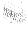
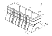
図1に、本発明のシリンダブロックを含めて構成したエンジンの斜視構造を示す。
In the present embodiment, it is assumed that the cylinder block according to the present invention is embodied as a cylinder block of an in-line four-cylinder engine.
<Engine structure>
FIG. 1 shows a perspective structure of an engine including the cylinder block of the present invention.
エンジン1は、大きくはシリンダブロック11、シリンダヘッド12、オイルパン13及びクランクシャフト14を備えて構成される。
シリンダヘッド12は、シリンダブロック11の頂部に組み付けられる。
The
The
オイルパン13は、シリンダブロック11の底部に組み付けられる。
クランクシャフト14は、シリンダブロック11のクランクケースCとオイルパン13との内部に形成された空間に配設される。
The
The
<シリンダブロックの構造>
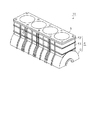
図2にシリンダブロック11の斜視構造を示す。
シリンダブロック11は、シリンダを含めて成形されたシリンダ構造体3と、クランクケースC及び外壁部51を含めて成形されたブロック本体5とを備えて構成される。
<Cylinder block structure>
FIG. 2 shows a perspective structure of the
The
シリンダ構造体3は、ブロック本体5の外壁部51に形成された本体フランジ部52への載置を通じてブロック本体5へ組み付けられる。
<シリンダ構造体の構造>
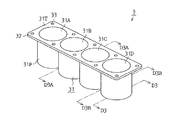
図3に、シリンダ構造体3の斜視構造を示す。
The
<Cylinder structure structure>
FIG. 3 shows a perspective structure of the
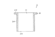
図4に、図3のD3−D3線に沿ったシリンダ構造体3の断面構造を示す。
シリンダ構造体3は、エンジンのピストンを収容するシリンダ31(第1シリンダ31A、第2シリンダ31B、第3シリンダ31C、第4シリンダ31D)と、同シリンダ31の外周面(シリンダ外周面31F)の上端部を取り囲むように形成されたシリンダフランジ部32とを含めて構成される。なお、シリンダ構造体3は、鋳造により一体成形される。
FIG. 4 shows a cross-sectional structure of the
The
本実施形態のエンジン1では、混合気の点火順序が「第1シリンダ31A→第3シリンダ31C→第4シリンダ31D→第2シリンダ31B」の順に設定されている。
クランクシャフト14においては、この点火順序に応じて、各シリンダのピストンのストローク位置(シリンダ内におけるピストンの位置)が次のように設定されている。即ち、第1シリンダ31Aと第4シリンダ31Dとにおいて、ピストンのストローク位置が同じ位置に設定されている。また、第2シリンダ31Bと第3シリンダ31Cとにおいて、ピストンのストローク位置が同じ位置に設定されている。
In the
In the
シリンダ構造体3において、シリンダフランジ部32側の端面(シリンダデッキ面31T)には、エンジン1のシリンダヘッド12が載置される。なお、シリンダデッキ面31Tと反対側の端面をシリンダ底面31Uとする。
In the
シリンダフランジ部32には、ボルトを挿入するためのボルト孔33がシリンダ31の軸線方向に設けられている。
<ブロック本体の構造>
図5に、ブロック本体5の斜視構造を示す。
Bolt holes 33 for inserting bolts are provided in the
<Block body structure>
FIG. 5 shows a perspective structure of the
図6に、図5のD5−D5線に沿ったブロック本体5の断面構造を示す。
ブロック本体5は、シリンダ31を収容するための外壁部51とクランクシャフト14を収容するためのクランクケースCとを含めて構成される。なお、ブロック本体5は、鋳造により一体成形される。
FIG. 6 shows a cross-sectional structure of the
The block
外壁部51の内周面(外壁部内周面51R)は、シリンダ構造体3のシリンダ外周面31Fと対応した形状に形成されている。
ブロック本体5へシリンダ構造体3を組み付けた状態において、外壁部内周面51Rとシリンダ外周面31Fとは所定の間隔を有して対向する。なお、シリンダブロック11においては、外壁部内周面51Rとシリンダ外周面31Fとの間に形成される空間がウォータージャケットとなる。
The inner peripheral surface (outer wall inner
In a state where the
外壁部51には、シリンダ構造体3のシリンダフランジ部32を載置するための本体フランジ部52が形成されている。
ブロック本体5の頂面(本体デッキ面51T)は、シリンダ構造体3のシリンダフランジ部32と当接される。
A main
The top surface (main
外壁部51には、シリンダ構造体3のボルト孔33と対応した位置にボルト孔53が形成されている。なお、シリンダヘッド12には、これらボルト孔33,53と対応するボルト孔が設けられている。そして、これら各ボルト孔へボルトを挿通させることにより、シリンダブロック11へシリンダヘッド12を組み付けることができる。
Bolt holes 53 are formed in the
ブロック本体5の外壁部51には、ウォータージャケットに対する冷却水の流入/流出に際して用いられる冷却水口54が設けられている。
ブロック本体5の内側において、外壁部51とクランクケースCとの境界には、シリンダ構造体3を載置するためのシリンダ支持部55が形成されている。このシリンダ支持部55は、ブロック本体5の内側の全周にわたって形成されている。
The
A
<ブロック本体の内部構造>
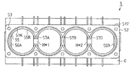
図7に、頂面側(図6の矢印VA方向)から見たブロック本体5の平面構造を示す。
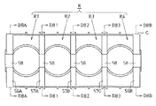
図8に、底面側(図6の矢印VB方向)から見たブロック本体5の平面構造を示す。
<Internal structure of block body>
FIG. 7 shows a planar structure of the
FIG. 8 shows a planar structure of the
クランクケースCにおいて、側壁56Aと側壁56Bとの間には複数の隔壁(第1隔壁57A、第2隔壁57B、第3隔壁57C)が設けられている。
側壁56A,56B及び隔壁57A,57B,57Cには、クランクシャフト14の軸受部58が形成されている。なお、クランクシャフト14は、そのジャーナルが軸受部58の内周面と対向する方向からクランクキャップを通じて支持されることにより、ブロック本体5に組み付けられる。
In the crankcase C, a plurality of partition walls (a
A bearing
クランクケースCの内部に形成されたクランク室Rは、これら隔壁57A,57B,57Cにより第1クランク室R1、第2クランク室R2、第3クランク室R3、第4クランク室R4に区画されている。
The crank chamber R formed inside the crankcase C is divided into a first crank chamber R1, a second crank chamber R2, a third crank chamber R3, and a fourth crank chamber R4 by the
第1クランク室R1は、クランクケースCの側壁56Aと第1隔壁57Aとに囲まれて区画形成されている。なお、第1クランク室R1は、第1シリンダ31Aと対応している。
The first crank chamber R1 is defined by being surrounded by the
第2クランク室R2は、第1隔壁57Aと第2隔壁57Bとに囲まれて区画形成されている。なお、第2クランク室R2は、第2シリンダ31Bと対応している。
第3クランク室R3は、第2隔壁57Bと第3隔壁57Cとに囲まれて区画形成されている。なお、第3クランク室R3は、第3シリンダ31Cと対応している。
The second crank chamber R2 is defined by being surrounded by the
The third crank chamber R3 is defined by being surrounded by the
第4クランク室R4は、クランクケースCの側壁56Bと第3隔壁57Cとに囲まれて区画形成されている。なお、第4クランク室R4は、第4シリンダ31Dと対応している。
The fourth crank chamber R4 is defined by being surrounded by the
第1クランク室R1と第2クランク室R2とは、第1隔壁連通部Hw1により連通されている。この第1隔壁連通部Hw1により、第1クランク室R1から第2クランク室R2へあるいは第2クランク室R2から第1クランク室R1への空気の移動が許容される。 The first crank chamber R1 and the second crank chamber R2 are communicated with each other through the first partition wall communication portion Hw1. The first partition wall communication portion Hw1 allows air movement from the first crank chamber R1 to the second crank chamber R2 or from the second crank chamber R2 to the first crank chamber R1.
第3クランク室R3と第4クランク室R4とは、第2隔壁連通部Hw2により連通されている。この第2隔壁連通部Hw2により、第3クランク室R3から第4クランク室R4へあるいは第4クランク室R4から第3クランク室R3への空気の移動が許容される。 The third crank chamber R3 and the fourth crank chamber R4 are communicated with each other by the second partition wall communication portion Hw2. The second partition wall communication portion Hw2 allows air movement from the third crank chamber R3 to the fourth crank chamber R4 or from the fourth crank chamber R4 to the third crank chamber R3.
<連通部が形成されている隔壁>
図9に、図8のD81−D81線に沿ったブロック本体5の断面構造を示す。
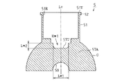
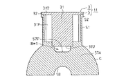
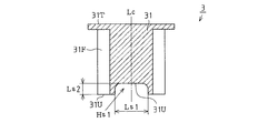
図10に、図1のD11−D11線に沿ったシリンダブロック11の断面構造を示す。
<The partition wall in which the communication part is formed>
FIG. 9 shows a cross-sectional structure of the
FIG. 10 shows a cross-sectional structure of the
第1隔壁連通部Hw1は、第1隔壁57Aの頂部において、凹状をなすように形成されている。即ち、第1隔壁連通部Hw1は、本体デッキ面51T側へ開口した凹部として第1隔壁57Aに形成されている。
The first partition wall communication portion Hw1 is formed in a concave shape at the top of the
これにより、ブロック本体5へシリンダ構造体3を組み付けた状態において(図10)、第1隔壁連通部Hw1はシリンダ31側へ開口した状態となる。また、シリンダ底面31Uと第1隔壁57Aの頂面(隔壁頂面57T)とが、所定の間隔を有して対向した状態となる。
Thereby, in the state which assembled | attached the
第1隔壁連通部Hw1は、クランクシャフト14の回転中心と直交する断面において、シリンダ31の中心軸Lcを中心線とする軸対称の形状に形成されている。
第1隔壁連通部Hw1の幅Lw1(シリンダ31の中心軸Lcと直交する方向の長さ)は、第1隔壁連通部Hw1の高さLw2(シリンダ31の軸方向における窪みの深さ)よりも大きく設定されている。即ち、第1隔壁連通部Hw1は、シリンダ31の中心軸Lcと直交する方向を長手方向とした形状に形成されている。なお、第1隔壁連通部Hw1は、「Lw1>Lw2」の条件が満たされる範囲において、ブロック本体5に設けられる油路やボルト孔等との干渉を回避できるように最適化された形状に設定される。
The first partition wall communication portion Hw1 is formed in an axisymmetric shape with the central axis Lc of the
The width Lw1 of the first partition wall communication portion Hw1 (the length in the direction orthogonal to the central axis Lc of the cylinder 31) is greater than the height Lw2 of the first partition wall communication portion Hw1 (the depth of the recess in the axial direction of the cylinder 31). It is set large. That is, the first partition wall communication portion Hw1 is formed in a shape whose longitudinal direction is a direction orthogonal to the central axis Lc of the
なお、図8のD83−D83線に沿ったブロック本体5の断面構造は、図9の断面構造と同様となっている。即ち、第2隔壁連通部Hw2は、第1隔壁連通部Hw1と同様の態様で第3隔壁57Cに形成されている。
The cross-sectional structure of the block
<連通部が形成されていない隔壁>
図11に、図8のD82−D82線に沿ったブロック本体5の断面構造を示す。
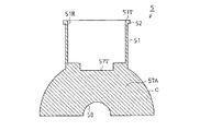
図12に、図1のD12−D12線に沿ったシリンダブロック11の断面構造を示す。
<Partition wall with no communication part>
FIG. 11 shows a cross-sectional structure of the block
FIG. 12 shows a cross-sectional structure of the
第2隔壁57Bの頂面(隔壁頂面57T)は、略平滑に形成されている。即ち、第1隔壁57A及び第3隔壁57Cとは異なり、隣接するクランク室間を連通するための凹部(連通部)が形成されていない。これにより、ブロック本体5へシリンダ構造体3を組み付けた状態において(図12)、シリンダ底面31Uと第1隔壁57Aの頂面(隔壁頂面57T)とが接触した状態となる。
The top surface of the
なお、図8のD8A−D8A線及びD8B−D8B線に沿ったブロック本体5の断面構造は、図11の断面構造と同様となっている。即ち、各側壁56A,56Bは、第2隔壁57Bと同様に、隣接するクランク室間を連通するための凹部(連通部)が形成されていない構造を有する。
In addition, the cross-sectional structure of the block
<実施形態の効果>
以上詳述したように、この第1実施形態にかかるシリンダブロックによれば、以下に列記するような効果が得られるようになる。
<Effect of embodiment>
As described above in detail, according to the cylinder block according to the first embodiment, the effects listed below can be obtained.
(1)本実施形態では、各別に形成されたシリンダ構造体3とブロック本体5との組み合わせを通じてシリンダブロック11を構成するとともに、隔壁連通部Hw1,Hw2をシリンダ側へ開口させて形成するようにしている。
(1) In the present embodiment, the
これにより、成形型に予め隔壁連通部Hw1,Hw2を設定してブロック本体5の成形を行うことが可能となるため、従来のシリンダブロックのように、不要な連通孔が形成されるといった事態を回避することができるようになる。
This makes it possible to mold the block
また、隔壁連通部Hw1,Hw2をシリンダ側へ開口させて、即ち隔壁上においてシリンダと最も近くなる位置に隔壁連通部Hw1,Hw2を形成するようにしているため、ピストンを通じてクランク室側(同クランク室と連続したシリンダの内部空間を含む)の空気が押圧されるとき、隣接するクランク室へそうした空気が早期に押し出されるようになる。 Further, the partition wall communication portions Hw1 and Hw2 are opened to the cylinder side, that is, the partition wall communication portions Hw1 and Hw2 are formed on the partition wall closest to the cylinder. When the air in the cylinder (including the internal space of the cylinder continuous with the chamber) is pressed, the air is quickly pushed out to the adjacent crank chamber.
これにより、クランク室の圧力変動にともなうポンピングロスをより効率的に低減することができるようになる。
このように、上記構造を採用することにより、クランクケースCへの不要な連通孔の形成を回避することのできる構造と、クランク室Rの圧力変動をより効率的に低減することのできる構造とをあわせて備えたシリンダブロック11を実現することができるようになる。
This makes it possible to more efficiently reduce the pumping loss that accompanies fluctuations in the pressure in the crank chamber.
Thus, by adopting the above structure, a structure that can avoid the formation of unnecessary communication holes in the crankcase C, and a structure that can more efficiently reduce pressure fluctuations in the crank chamber R. It is possible to realize the
(2)シリンダブロックにおいて、隣接したクランク室を連通することはポンピングロスの低減を図るうえで有効な対策となるが、これらクランク室に対応するシリンダについて、ピストンのストローク位置が同じに設定されている場合は、上記クランク室の間の隔壁に連通部を形成してもその連通部を通じて圧力変動の低減が図られるようにはならない。 (2) In the cylinder block, communication between adjacent crank chambers is an effective measure for reducing pumping loss. However, the piston stroke position is set to be the same for the cylinders corresponding to these crank chambers. In this case, even if a communication portion is formed in the partition wall between the crank chambers, the pressure fluctuation cannot be reduced through the communication portion.
そこで、本実施形態では、ピストンのストローク位置が同じとなる第2クランク室R2と第3クランク室R3とを連通しないようにしている。これにより、不要に連通部が形成されることによるシリンダブロック11の剛性の低下を回避することができるようになる。
Therefore, in this embodiment, the second crank chamber R2 and the third crank chamber R3, which have the same piston stroke position, are prevented from communicating with each other. As a result, it is possible to avoid a decrease in the rigidity of the
(3)本実施形態では、連通部Hw1,Hw2を隔壁57A,57Cの最上部(シリンダ31に最も接近した位置)に形成するようにしている。
これにより、ピストンの移動にともなってクランク室側の空気が押圧されたとき、慣性がより大きくなる前にそうした空気が隣接するクランク室へ導入されるようになるため、より効率的にポンピングロスを低減することができるようになる。
(3) In this embodiment, the communication portions Hw1 and Hw2 are formed at the uppermost portions (positions closest to the cylinder 31) of the
As a result, when the air on the crank chamber side is pressed as the piston moves, such air is introduced into the adjacent crank chamber before the inertia becomes larger. Can be reduced.
(4)隔壁に連通孔が形成されたシリンダブロックにおいては、クランクシャフトへ燃焼圧が作用することにより、連通孔周囲に応力集中が生じるようになる。そして、この応力集中が過度に大きくなることにより、隔壁の破損をまねくことが懸念されている。 (4) In the cylinder block in which the communication hole is formed in the partition wall, stress concentration occurs around the communication hole due to the combustion pressure acting on the crankshaft. And there is a concern that this stress concentration becomes excessively large, leading to breakage of the partition walls.
この点、本実施形態では、連通孔に代えて連通部Hw1,Hw2を隔壁57A,57Cの最上部に形成するようにしている。これにより、連通部Hw1,Hw2とクランクジャーナルとの距離が長くなるため、連通部Hw1,Hw2への応力集中を極力低減することができるようになる。
In this regard, in the present embodiment, communication portions Hw1 and Hw2 are formed at the uppermost portions of the
(5)本実施形態では、各連通部Hw1,Hw2について、連通部の幅Lw1を連通部の高さLw2よりも大きく設定するようにしている。
こうした構成によれば、シリンダ31側へ開口させて連通部Hw1,Hw2を形成する場合において、幅Lw1を高さLw2以下に設定したときと比べて、隣接するクランク室へより早期に空気が押し出されるようになる。このため、ポンピングロスの低減効果が高められるようになる。
(5) In the present embodiment, for each communication portion Hw1, Hw2, the width Lw1 of the communication portion is set to be larger than the height Lw2 of the communication portion.
According to such a configuration, when the communication portions Hw1 and Hw2 are formed by opening to the
このように、上記構成を採用することで、隔壁上の限られたスペースを有効に利用して、ポンピングロスの低減により適した連通構造を実現することができるようになる。
(6)本実施形態では、クランクシャフト14の回転中心と直交する断面において、第1隔壁連通部Hw1をシリンダ31の中心軸Lcを中心線とする軸対称の形状として形成している。
As described above, by adopting the above configuration, it is possible to realize a communication structure more suitable for reducing the pumping loss by effectively utilizing the limited space on the partition wall.
(6) In this embodiment, in the cross section orthogonal to the rotation center of the
これにより、ピストンによりクランク室側の空気が隣接したクランク室へ押し出されるとき、空気の流れの均一化が図られるため、より効率的にポンピングロスを低減することができるようになる。 Thereby, when the air on the crank chamber side is pushed out to the adjacent crank chamber by the piston, the air flow is made uniform, so that the pumping loss can be reduced more efficiently.
(7)従来のシリンダブロックにおいては、切削加工により連通孔を形成するため、残留応力によりシリンダブロックの破損をまねくことが考えられる。
この点、本実施形態では、シリンダ構造体3とブロック本体5との組み合わせを通じてシリンダブロック11を構成するとともに、隔壁連通部Hw1,Hw2を含めてブロック本体5の成形を行うようにしている。これにより、切削加工による連通構造の形成が不要となるため、シリンダブロックへの残留応力の発生を回避することができるようになる。
(7) In the conventional cylinder block, since the communication hole is formed by cutting, it is conceivable that the cylinder block is damaged by the residual stress.
In this respect, in the present embodiment, the
(第2実施形態)
本発明の第2実施形態について、図13及び図14を参照して説明する。なお、図13及び図14は、クランクシャフトの中心軸と直交する断面を示している。
(Second Embodiment)
A second embodiment of the present invention will be described with reference to FIGS. 13 and 14 show a cross section orthogonal to the center axis of the crankshaft.
本実施形態のシリンダブロックは、前記第1実施形態のシリンダブロックに次のような変更を加えた構造を有する。即ち、シリンダ構造体3において、隣接するシリンダ31の内部空間を連通する連通部をシリンダ底面31U側へ開口させて形成している。
The cylinder block of the present embodiment has a structure in which the following changes are added to the cylinder block of the first embodiment. That is, in the
<連通部の形成態様>
図13に、図3のD3A−D3A線に沿った断面構造に相当するシリンダ構造体3の断面構造を示す。
<Formation of communication part>
FIG. 13 shows a cross-sectional structure of the
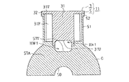
図14に、図1のD11−D11線に沿った断面構造に相当するシリンダブロック11の断面構造を示す。
シリンダ構造体3において、第1シリンダ31Aの周壁と第2シリンダ31Bの周壁とがつながった箇所には、第1シリンダ31Aの内部空間と第2シリンダ31Bの内部空間とを連通するシリンダ連通部Hsが形成されている。
FIG. 14 shows a cross-sectional structure of the
In the
シリンダ連通部Hsは、第1シリンダ31A及び第2シリンダ31Bの底面において、凹状をなすように形成されている。即ち、シリンダ連通部Hsは、シリンダ底面31U側へ開口して形成されている。
The cylinder communication portion Hs is formed in a concave shape on the bottom surfaces of the
これにより、ブロック本体5へシリンダ構造体3を組み付けた状態において(図14)、シリンダ連通部Hsはブロック本体5側へ開口した状態となる。また、シリンダ底面31Uと隔壁頂面57Tとが、所定の間隔を有して対向した状態となる。
Thereby, in the state which assembled | attached the
シリンダ連通部Hsは、クランクシャフト14の回転中心と直交する断面において、シリンダ31の中心軸Lcを中心とする軸対称の形状に形成されている。
シリンダ連通部Hsの幅Ls1(シリンダ31の中心軸Lcと直交する方向の長さ)は、シリンダ連通部Hsの高さLs2(シリンダ31の軸方向における窪みの高さ)よりも大きく設定されている。即ち、シリンダ連通部Hsは、シリンダ31の中心軸Lcと直交する方向を長手方向とした形状に形成されている。
The cylinder communication portion Hs is formed in an axisymmetric shape around the central axis Lc of the
The width Ls1 of the cylinder communication portion Hs (the length in the direction orthogonal to the central axis Lc of the cylinder 31) is set larger than the height Ls2 of the cylinder communication portion Hs (the height of the recess in the axial direction of the cylinder 31). Yes. That is, the cylinder communication portion Hs is formed in a shape whose longitudinal direction is a direction orthogonal to the central axis Lc of the
シリンダ連通部Hsの高さLs2は、燃焼室の容積が最も大きい状態において、シリンダ連通部Hsとピストンリングとが干渉しないように設定される。
なお、図3のD3B−D3B線に沿った断面構造に相当する本実施形態のシリンダ構造体3の断面構造は、図13の断面構造と同様となっている。即ち、第3シリンダ31Cの周壁と第4シリンダ31Dの周壁とがつながった箇所にも、第1シリンダ31A及び第2シリンダ31Bと同様の態様でシリンダ連通部Hsに形成されている。
The height Ls2 of the cylinder communication portion Hs is set so that the cylinder communication portion Hs and the piston ring do not interfere with each other when the volume of the combustion chamber is the largest.
In addition, the cross-sectional structure of the
<作用効果>
以上詳述したように、この第2実施形態にかかるシリンダブロックによれば、先の第1実施形態による前記(1)〜(7)の効果に加えて、以下に示すような効果が得られるようになる。
<Effect>
As described above in detail, according to the cylinder block according to the second embodiment, the following effects can be obtained in addition to the effects (1) to (7) according to the first embodiment. It becomes like this.
(8)本実施形態では、隔壁連通部Hw1,Hw2に加えて、シリンダ31にシリンダ連通部Hsを形成するようにしている。これにより、ピストンにより隣接したクランク室へ押し出される空気の量が増量されるため、より効率的にポンピングロスを低減することができるようになる。
(8) In the present embodiment, the cylinder communication portion Hs is formed in the
<変更例>
なお、上記第2実施形態は、これを適宜変更した、例えば次のような形態として実施することもできる。
<Example of change>
In addition, the said 2nd Embodiment can also be implemented as the following forms which changed this suitably, for example.
・上記第2実施形態では、隔壁連通部Hw1,Hw2及びシリンダ連通部Hsをそれぞれ形成する構成としたが、隔壁連通部Hw1,Hw2を形成せずにシリンダ連通部Hsのみを通じてポンピングロスの低減を図ることもできる。 In the second embodiment, the partition wall communication portions Hw1 and Hw2 and the cylinder communication portion Hs are formed. However, the pumping loss is reduced only through the cylinder communication portion Hs without forming the partition wall communication portions Hw1 and Hw2. You can also plan.
・上記第2実施形態では、クランクシャフト14の回転中心と直交する断面において、シリンダ連通部Hsを略長方形状に形成する構成としたが、シリンダ連通部Hsをその他の形状に変更することもできる。要するに、シリンダ連通部Hsの幅Ls1がシリンダ連通部Hsの高さLs2よりも大きく設定されている形状であれば、シリンダ連通部Hsの形状は適宜変更可能である。
In the second embodiment, the cylinder communication portion Hs is formed in a substantially rectangular shape in the cross section orthogonal to the rotation center of the
(その他の実施形態)
その他、上記各実施形態に共通して変更することができる要素を以下に列挙する。
・上記各実施形態では、クランクシャフト14の回転中心と直交する断面において、隔壁連通部Hw1,Hw2を略長方形状に形成する構成としたが、これら隔壁連通部Hw1,Hw2をその他の形状に変更することもできる。要するに、隔壁連通部Hw1,Hw2の幅Lw1が隔壁連通部Hw1,Hw2の高さLw2よりも大きく設定されている形状であれば、隔壁連通部Hw1,Hw2の形状は適宜変更可能である。
(Other embodiments)
In addition, elements that can be changed in common with each of the above embodiments are listed below.
In each of the above embodiments, the partition wall communication portions Hw1 and Hw2 are formed in a substantially rectangular shape in a cross section perpendicular to the rotation center of the
・上記各実施形態では、直列4気筒型エンジンのシリンダブロックとして本発明を具体化した場合を想定したが、本発明の適用対象となるシリンダブロックは直列4気筒型エンジンのシリンダブロックに限られるものではない。要するに、複数のシリンダを有するエンジンのシリンダブロックであれば、いずれのシリンダブロックに対しても本発明を適用することができる。 In each of the above embodiments, it is assumed that the present invention is embodied as a cylinder block of an in-line four-cylinder engine. However, the cylinder block to which the present invention is applied is limited to a cylinder block of an in-line four-cylinder engine. is not. In short, the present invention can be applied to any cylinder block as long as it is a cylinder block of an engine having a plurality of cylinders.
1…エンジン、11…シリンダブロック、12…シリンダヘッド、13…オイルパン、14…クランクシャフト、C…クランクケース、3…シリンダ構造体、31…シリンダ、31A…第1シリンダ、31B…第2シリンダ、31C…第3シリンダ、31D…第4シリンダ、31F…シリンダ外周面、31T…シリンダデッキ面、31U…シリンダ底面、32…シリンダフランジ部、33…ボルト孔、5…ブロック本体、51…外壁部、51R…外壁部内周面、51T…本体デッキ面、52…本体フランジ部、53…ボルト孔、54…冷却水口、55…シリンダ支持部、55R…シリンダ支持部内周面、56A…側壁、56B…側壁、57A…第1隔壁、57B…第2隔壁、57C…第3隔壁、57T…隔壁頂面、58…軸受部、R…クランク室、R1…第1クランク室、R2…第2クランク室、R3…第3クランク室、R4…第4クランク室、Hw1…第1隔壁連通部、Hw2…第2隔壁連通部、Hs…シリンダ連通部。
DESCRIPTION OF
Claims (9)
複数のシリンダを含めて形成されたシリンダ構造体と、
前記シリンダを収容する外壁部、前記エンジンのクランクシャフトを収容するクランクケース及び前記クランクケースの内部空間を前記シリンダの数に応じた複数のクランク室に区画する隔壁を含めて一体形成されたブロック本体との組み合わせにより構成するとともに、
前記隔壁に、隣接したクランク室を連通する隔壁連通部を前記シリンダ側へ開口させて形成した
ことを特徴とするエンジンのシリンダブロック。 Engine cylinder block,
A cylinder structure formed including a plurality of cylinders;
A block main body integrally formed including an outer wall portion that accommodates the cylinder, a crankcase that accommodates the crankshaft of the engine, and a partition that divides the internal space of the crankcase into a plurality of crank chambers corresponding to the number of cylinders In combination with
A cylinder block for an engine, wherein the partition wall is formed by opening a partition wall communication portion communicating with an adjacent crank chamber to the cylinder side.
複数のシリンダを含めて形成されたシリンダ構造体と、
前記シリンダを収容する外壁部、前記エンジンのクランクシャフトを収容するクランクケース及び前記クランクケースの内部空間を前記シリンダの数に応じた複数のクランク室に区画する隔壁を含めて一体形成されたブロック本体との組み合わせにより構成するとともに、
前記シリンダに、隣接したシリンダの内部空間を連通するシリンダ連通部を前記ブロック本体側へ開口させて形成した
ことを特徴とするエンジンのシリンダブロック。 Engine cylinder block,
A cylinder structure formed including a plurality of cylinders;
A block main body integrally formed including an outer wall portion that accommodates the cylinder, a crankcase that accommodates the crankshaft of the engine, and a partition that divides the internal space of the crankcase into a plurality of crank chambers corresponding to the number of cylinders In combination with
A cylinder block for an engine, wherein a cylinder communication portion that communicates with an internal space of an adjacent cylinder is opened to the block main body.
複数のシリンダを含めて形成されたシリンダ構造体と、
前記シリンダを収容する外壁部、前記エンジンのクランクシャフトを収容するクランクケース及び前記クランクケースの内部空間を前記シリンダの数に応じた複数のクランク室に区画する隔壁を含めて一体形成されたブロック本体との組み合わせにより構成するとともに、
前記隔壁に、隣接したクランク室を連通する隔壁連通部を前記シリンダ側へ開口させて形成し、
前記シリンダに、隣接したシリンダの内部空間を連通するシリンダ連通部を前記ブロック本体側へ開口させて形成した
ことを特徴とするエンジンのシリンダブロック。 Engine cylinder block,
A cylinder structure formed including a plurality of cylinders;
A block main body integrally formed including an outer wall portion that accommodates the cylinder, a crankcase that accommodates the crankshaft of the engine, and a partition that divides the internal space of the crankcase into a plurality of crank chambers corresponding to the number of cylinders In combination with
The partition wall is formed by opening a partition wall communication portion communicating with an adjacent crank chamber to the cylinder side,
A cylinder block for an engine, wherein a cylinder communication portion that communicates with an internal space of an adjacent cylinder is opened to the block main body.
前記隔壁連通部を前記クランクシャフトの中心軸と直交する断面上で前記シリンダの中心軸を中心線とする軸対称の形状に形成した
ことを特徴とするエンジンのシリンダブロック。 In the cylinder block of the engine according to claim 1 or 3,
The cylinder block of an engine, wherein the partition wall communication portion is formed in an axisymmetric shape with a center line of the center axis of the cylinder on a cross section orthogonal to the center axis of the crankshaft.
ピストンのストローク位置がそれぞれ異なる位置に設定されており、且つ隣接して配設されている2つのシリンダについて、これらシリンダの各々に対応するクランク室の間に設けられた隔壁のみに前記隔壁連通部を形成した
ことを特徴とするエンジンのシリンダブロック。 The cylinder block of the engine according to claim 1, 3 or 4,
For the two cylinders in which the stroke positions of the pistons are different from each other and which are arranged adjacent to each other, only the partition wall provided between the crank chambers corresponding to each of the cylinders is connected to the partition wall communication portion. A cylinder block of an engine characterized by forming.
前記シリンダ連通部を前記クランクシャフトの中心軸と直交する断面上で前記シリンダの中心軸を中心線とする軸対称の形状に形成した
ことを特徴とするエンジンのシリンダブロック。 The engine cylinder block according to claim 2 or 3,
The cylinder block of the engine, wherein the cylinder communication portion is formed in an axisymmetric shape with the center axis of the cylinder as a center line on a cross section orthogonal to the center axis of the crankshaft.
ピストンのストローク位置がそれぞれ異なる位置に設定されており、且つ隣接して配設されている2つのシリンダについて、これらシリンダの間のみに前記シリンダ連通部を形成した
ことを特徴とするエンジンのシリンダブロック。 The cylinder block of the engine according to claim 2, 3 or 6,
Cylinder block for an engine, wherein the stroke positions of the pistons are set at different positions, and the cylinder communicating portion is formed only between the two cylinders arranged adjacent to each other. .
前記クランクシャフトの中心軸と直交する断面上の前記隔壁連通部について、前記シリンダの軸方向と直交する方向の長さを隔壁連通部幅、前記シリンダの軸方向の長さを隔壁連通部高さとしたときに、前記隔壁連通部幅を前記隔壁連通部高さよりも大きく設定して前記隔壁連通部を形成した
ことを特徴とするエンジンのシリンダブロック。 In the cylinder block of the engine according to claim 1 or 3 or 4 or 5,
With respect to the partition wall communication portion on the cross section orthogonal to the center axis of the crankshaft, the length in the direction orthogonal to the axial direction of the cylinder is the partition wall communication portion width, and the length in the axial direction of the cylinder is the partition wall communication portion height. In this case, the partition wall communication portion is formed by setting the partition wall communication portion width to be larger than the partition wall communication portion height.
前記クランクシャフトの中心軸と直交する断面上の前記シリンダ連通部について、前記シリンダの軸方向と直交する方向の長さをシリンダ連通部幅、前記シリンダの軸方向の長さをシリンダ連通部高さとしたときに、前記シリンダ連通部幅を前記シリンダ連通部高さよりも大きく設定して前記シリンダ連通部を形成した
ことを特徴とするエンジンのシリンダブロック。 In the cylinder block of the engine according to claim 2 or 3 or 6 or 7,
Regarding the cylinder communication portion on the cross section orthogonal to the central axis of the crankshaft, the length in the direction orthogonal to the axial direction of the cylinder is the cylinder communication portion width, and the length in the axial direction of the cylinder is the cylinder communication portion height. In this case, the cylinder communication portion is formed by setting the width of the cylinder communication portion larger than the height of the cylinder communication portion.
Priority Applications (3)
| Application Number | Priority Date | Filing Date | Title |
|---|---|---|---|
| JP2004107224A JP2005291089A (en) | 2004-03-31 | 2004-03-31 | Engine cylinder block |
| US11/077,075 US7036479B2 (en) | 2004-03-31 | 2005-03-11 | Cylinder block for engine |
| DE102005014548A DE102005014548A1 (en) | 2004-03-31 | 2005-03-30 | Engine cylinder block |
Applications Claiming Priority (1)
| Application Number | Priority Date | Filing Date | Title |
|---|---|---|---|
| JP2004107224A JP2005291089A (en) | 2004-03-31 | 2004-03-31 | Engine cylinder block |
Publications (2)
| Publication Number | Publication Date |
|---|---|
| JP2005291089A true JP2005291089A (en) | 2005-10-20 |
| JP2005291089A5 JP2005291089A5 (en) | 2007-05-17 |
Family
ID=35052896
Family Applications (1)
| Application Number | Title | Priority Date | Filing Date |
|---|---|---|---|
| JP2004107224A Pending JP2005291089A (en) | 2004-03-31 | 2004-03-31 | Engine cylinder block |
Country Status (3)
| Country | Link |
|---|---|
| US (1) | US7036479B2 (en) |
| JP (1) | JP2005291089A (en) |
| DE (1) | DE102005014548A1 (en) |
Cited By (3)
| Publication number | Priority date | Publication date | Assignee | Title |
|---|---|---|---|---|
| JP2008232079A (en) * | 2007-03-22 | 2008-10-02 | Aichi Mach Ind Co Ltd | Cylinder block of internal-combustion engine and method of manufacturing the cylinder block |
| JP2010174778A (en) * | 2009-01-30 | 2010-08-12 | Honda Motor Co Ltd | Multi-cylinder internal combustion engine |
| CN116717367A (en) * | 2022-03-07 | 2023-09-08 | 丰田自动车株式会社 | internal combustion engine |
Families Citing this family (2)
| Publication number | Priority date | Publication date | Assignee | Title |
|---|---|---|---|---|
| JP2004218546A (en) * | 2003-01-15 | 2004-08-05 | Toyota Motor Corp | Cylinder block, cylinder head and engine body |
| DE102005030850B4 (en) * | 2005-07-01 | 2008-05-29 | Mtu Friedrichshafen Gmbh | Crankcase with bottom plate |
Family Cites Families (4)
| Publication number | Priority date | Publication date | Assignee | Title |
|---|---|---|---|---|
| JP2000136752A (en) * | 1998-10-31 | 2000-05-16 | Honda Motor Co Ltd | Multi-cylinder engine crankcase |
| JP3800906B2 (en) | 2000-02-28 | 2006-07-26 | スズキ株式会社 | 4-cycle multi-cylinder engine cylinder block structure |
| JP3959959B2 (en) | 2000-12-13 | 2007-08-15 | スズキ株式会社 | Engine cylinder vent structure |
| JP2003074408A (en) * | 2001-08-31 | 2003-03-12 | Honda Motor Co Ltd | Cylinder block for multi-cylinder engine |
-
2004
- 2004-03-31 JP JP2004107224A patent/JP2005291089A/en active Pending
-
2005
- 2005-03-11 US US11/077,075 patent/US7036479B2/en not_active Expired - Fee Related
- 2005-03-30 DE DE102005014548A patent/DE102005014548A1/en not_active Withdrawn
Cited By (4)
| Publication number | Priority date | Publication date | Assignee | Title |
|---|---|---|---|---|
| JP2008232079A (en) * | 2007-03-22 | 2008-10-02 | Aichi Mach Ind Co Ltd | Cylinder block of internal-combustion engine and method of manufacturing the cylinder block |
| JP2010174778A (en) * | 2009-01-30 | 2010-08-12 | Honda Motor Co Ltd | Multi-cylinder internal combustion engine |
| CN116717367A (en) * | 2022-03-07 | 2023-09-08 | 丰田自动车株式会社 | internal combustion engine |
| JP7601032B2 (en) | 2022-03-07 | 2024-12-17 | トヨタ自動車株式会社 | Internal combustion engine |
Also Published As
| Publication number | Publication date |
|---|---|
| US20050217628A1 (en) | 2005-10-06 |
| US7036479B2 (en) | 2006-05-02 |
| DE102005014548A1 (en) | 2005-10-27 |
Similar Documents
| Publication | Publication Date | Title |
|---|---|---|
| KR100825366B1 (en) | Cylinder block of engine | |
| JP2009191779A (en) | Piston of internal combustion engine | |
| US5850814A (en) | Cylinder bore isolator core for casting engine cylinder blocks | |
| JP2015031278A (en) | Engine housing for internal combustion engine and internal combustion engine having engine housing | |
| JP2021055622A (en) | cylinder head | |
| JP2005291089A (en) | Engine cylinder block | |
| US6324961B1 (en) | Oil passage arrangement in a piston | |
| US6158402A (en) | Engine block structure in multi-cylinder engine | |
| JP2007120506A (en) | Multi-cylinder engine | |
| CN100422577C (en) | Crankshaft support structure of internal combustion engine | |
| JP2005351261A (en) | Internal combustion engine | |
| CN100497922C (en) | Engine cylinder | |
| JP4586035B2 (en) | Cylinder block of internal combustion engine and manufacturing method thereof | |
| JP2009091989A (en) | Baffle plate | |
| US8800507B2 (en) | Interlocking piston barrels in a V-twin motorcycle engine | |
| JP2005291089A5 (en) | ||
| JP2002242753A (en) | Cylinder block structure of engine | |
| JP4297618B2 (en) | Cylinder block cooling structure for internal combustion engine | |
| JP2006070795A (en) | Internal combustion engine | |
| CN111648875B (en) | Cylinder body | |
| EP1869299B1 (en) | Internal combustion engine | |
| JP4396390B2 (en) | Cylinder block structure and manufacturing method thereof | |
| JPH088281Y2 (en) | Integrated cylinder block for internal combustion engine | |
| JP2002242755A (en) | Cylinder block structure of engine | |
| US20200355139A1 (en) | Engine piston and method for manufacturing the same |
Legal Events
| Date | Code | Title | Description |
|---|---|---|---|
| A521 | Written amendment |
Free format text: JAPANESE INTERMEDIATE CODE: A523 Effective date: 20070327 |
|
| A621 | Written request for application examination |
Free format text: JAPANESE INTERMEDIATE CODE: A621 Effective date: 20070327 |
|
| A131 | Notification of reasons for refusal |
Free format text: JAPANESE INTERMEDIATE CODE: A131 Effective date: 20081216 |
|
| A977 | Report on retrieval |
Free format text: JAPANESE INTERMEDIATE CODE: A971007 Effective date: 20081218 |
|
| A02 | Decision of refusal |
Free format text: JAPANESE INTERMEDIATE CODE: A02 Effective date: 20090512 |