JP2005291085A - Titanium alloy valve lifter for engine and manufacturing method thereof - Google Patents
Titanium alloy valve lifter for engine and manufacturing method thereof Download PDFInfo
- Publication number
- JP2005291085A JP2005291085A JP2004107170A JP2004107170A JP2005291085A JP 2005291085 A JP2005291085 A JP 2005291085A JP 2004107170 A JP2004107170 A JP 2004107170A JP 2004107170 A JP2004107170 A JP 2004107170A JP 2005291085 A JP2005291085 A JP 2005291085A
- Authority
- JP
- Japan
- Prior art keywords
- valve lifter
- hardened layer
- titanium alloy
- valve
- vickers hardness
- Prior art date
- Legal status (The legal status is an assumption and is not a legal conclusion. Google has not performed a legal analysis and makes no representation as to the accuracy of the status listed.)
- Granted
Links
Images
Landscapes
- Valve-Gear Or Valve Arrangements (AREA)
Abstract
【課題】 軽量で,且つ高強度であり,その上,優れた摺動特性を有するエンジン用チタン合金製バルブリフタを提供する。
【解決手段】 バルブリフタ16は,筒状部19および端壁状部20を持ち,且つチタン合金よりなるバルブリフタ本体21と,動弁カムと摺動する摺動面を形成すべく,端壁状部20外面に形成された第1の硬化層23と,エンジン本体のガイド孔を摺動する摺動面を形成すべく,筒状部19外周面に形成された第2の硬化層25とを有する。第1の硬化層23のビッカース硬さH1 が500HV0.1<H1 ≦800HV0.1であり,第2の硬化層25のビッカース硬さH2 が300HV0.1≦H2 ≦500HV0.1である。
【選択図】 図2PROBLEM TO BE SOLVED: To provide a valve lifter made of a titanium alloy for an engine which is light in weight and high in strength and has excellent sliding characteristics.
A valve lifter 16 has a cylindrical portion 19 and an end wall portion 20, and an end wall portion to form a sliding surface that slides against a valve lifter body 21 made of a titanium alloy and a valve cam. 20 has a first hardened layer 23 formed on the outer surface, and a second hardened layer 25 formed on the outer peripheral surface of the cylindrical portion 19 to form a sliding surface that slides through the guide hole of the engine body. . The Vickers hardness H 1 of the first hardened layer 23 is 500HV0.1 <H 1 ≦ 800HV0.1, and the Vickers hardness H 2 of the second hardened layer 25 is 300HV0.1 ≦ H 2 ≦ 500HV0.1. is there.
[Selection] Figure 2
Description
本発明はエンジン用チタン合金製バルブリフタおよびその製造方法に関する。 The present invention relates to a titanium alloy valve lifter for an engine and a method for manufacturing the same.
自動車等のエンジンにおいて,そのバルブリフタをチタン合金より構成すれば,その軽量化と高強度化を達成することができるのであるが,耐摩耗性については問題が残る。 In an engine such as an automobile, if the valve lifter is made of a titanium alloy, its weight reduction and strength can be achieved, but there remains a problem with wear resistance.
そこで,バルブリフタとして,筒状部およびその筒状部の一端を閉鎖する端壁状部を持ち,且つチタン合金よりなるバルブリフタ本体と,動弁カムと摺動する摺動面を形成すべく,端壁状部外面に取付けられた,炭素鋼,ステンレス鋼等の硬質金属よりなるアジャスティングシムとを有し,またエンジン本体のガイド孔を摺動する摺動面を形成すべく,筒状部外周面を酸化膜により覆ったものが開発されている(特許文献1参照)。
しかしながら,前記のように硬質金属,例えば鋼よりなるアジャスティングシムを用いると,バルブリフタの軽量化の目的が損なわれるだけでなく,そのバルブリフタの製造工数および製造コストの上昇を来たす,という問題を生じた。 However, the use of an adjusting shim made of hard metal such as steel as described above not only impairs the purpose of reducing the weight of the valve lifter, but also increases the man-hours and costs of the valve lifter. It was.
本発明は,軽量で,且つ高強度であり,その上,優れた摺動特性を有する,つまり良好な耐摩耗性を持つと共に相手材である動弁カムおよびガイド孔の孔壁に対する攻撃性の低い前記バルブリフタおよびその製造方法を提供することを目的とする。 The present invention is lightweight and high in strength, and also has excellent sliding characteristics, that is, good wear resistance and aggressiveness against the valve cam and guide hole wall which are counterparts. It is an object of the present invention to provide a low valve lifter and a method for manufacturing the same.
前記目的を達成するため第1発明によれば,筒状部およびその筒状部の一端を閉鎖する端壁状部を持ち,且つチタン合金よりなるバルブリフタ本体と,動弁カムと摺動する摺動面を形成すべく,前記端壁状部外面に形成された第1の硬化層と,エンジン本体のガイド孔を摺動する摺動面を形成すべく,前記筒部外周面に形成された第2の硬化層とを有し,前記第1の硬化層のビッカース硬さH1 が500HV0.1<H1 ≦800HV0.1であり,前記第2の硬化層のビッカース硬さH2 が300HV0.1≦H2 ≦500HV0.1であるエンジン用チタン合金製バルブリフタが提供される。 In order to achieve the above object, according to the first invention, a tubular portion and an end wall-like portion that closes one end of the tubular portion, a valve lifter body made of a titanium alloy, and a slide that slides on a valve cam. A first hardened layer formed on the outer surface of the end wall portion to form a moving surface and a sliding surface that slides on a guide hole of the engine body are formed on the outer peripheral surface of the cylinder portion. and a second cured layer, Vickers hardness H 1 of the first cured layer is 500HV0.1 <H 1 ≦ 800HV0.1, Vickers hardness of H 2 the second hardened layer 300HV0 .1 ≦ H 2 ≦ 500HV0.1 a is titanium alloy valve lifter for an engine is provided.
また第2発明によれば,前記チタン合金は,0.30wt%≦Fe≦1.50wt%,0.20wt%≦O≦0.70wt%および不可避不純物を含む残部Tiよりなる,エンジン用チタン合金製バルブリフタが提供される。 According to the second invention, the titanium alloy is composed of 0.30 wt% ≦ Fe ≦ 1.50 wt%, 0.20 wt% ≦ O ≦ 0.70 wt% and the balance Ti containing inevitable impurities, and the engine titanium alloy A valve lifter is provided.
さらに第3発明によれば,エンジン本体のガイド孔内に挿入される筒部およびその筒部の一端を閉鎖して動弁カムと対向する端壁部を持つチタン合金製バルブリフタ本体用素材に,大気中にて1次酸化処理を施して,前記バルブリフタ本体用素材全面に1次酸化処理後の硬化層を形成された第1の中間体を得る工程と,前記筒部外周面に機械加工を施して第2中間体を得る工程と,前記第2中間体に,大気中にて2次酸化処理を施して,前記端壁部外面に第1の硬化層を形成し,前記筒部外周面に第2の硬化層を形成する工程とを用いて,前記第1の硬化層のビッカース硬さH1 が500HV0.1<H1 ≦800HV0.1であり,前記第2の硬化層のビッカース硬さH2 が300HV0.1≦H2 ≦500HV0.1であるチタン合金製バルブリフタを得る,エンジン用チタン合金製バルブリフタの製造方法が提供される。 Further, according to the third aspect of the present invention, there is provided a titanium alloy valve lifter body material having a cylinder portion inserted into the guide hole of the engine body and an end wall portion which is closed at one end of the cylinder portion and faces the valve cam. Performing a primary oxidation treatment in the atmosphere to obtain a first intermediate in which a cured layer after the primary oxidation treatment is formed on the entire surface of the valve lifter body material; and machining the outer peripheral surface of the cylindrical portion. A step of obtaining a second intermediate, and subjecting the second intermediate to a secondary oxidation treatment in the atmosphere to form a first hardened layer on the outer surface of the end wall, And the step of forming the second hardened layer, the Vickers hardness H 1 of the first hardened layer is 500HV0.1 <H 1 ≦ 800HV0.1, and the Vickers hardness of the second hardened layer is titanium alloy bar is H 2 is 300HV0.1 ≦ H 2 ≦ 500HV0.1 is A titanium alloy valve lifter manufacturing method for obtaining a lubricator is provided.
さらにまた第4発明によれば,1次酸化処理を施す際の加熱温度T1 をT1 ≧650℃に設定し,2次酸化処理を施す際の加熱温度T2 を400℃<T2 <650℃に設定する,エンジン用チタン合金製バルブリフタの製造方法が提供される。 Furthermore, according to the fourth aspect of the invention, the heating temperature T 1 for performing the primary oxidation treatment is set to T 1 ≧ 650 ° C., and the heating temperature T 2 for performing the secondary oxidation treatment is set to 400 ° C. <T 2 < There is provided a method for manufacturing a titanium alloy valve lifter for an engine set to 650 ° C.
また第5発明によれば,前記チタン合金は,0.30wt%≦Fe≦1.50wt%,0.20wt%≦O≦0.70wt%および不可避不純物を含む残部Tiよりなる,エンジン用チタン合金製バルブリフタの製造方法が提供される。 According to a fifth aspect of the present invention, the titanium alloy is composed of 0.30 wt% ≦ Fe ≦ 1.50 wt%, 0.20 wt% ≦ O ≦ 0.70 wt% and the balance Ti containing inevitable impurities, and the titanium alloy for engines. A method of manufacturing a valve lifter is provided.
バルブリフタにおいて,動弁カムとの摺動面に要求される摺動条件はガイド孔との摺動面に要求される摺動条件よりも厳しい。 In the valve lifter, the sliding condition required for the sliding surface with the valve cam is stricter than the sliding condition required for the sliding surface with the guide hole.
第1発明においては,動弁カムに対応する第1の硬化層のビッカース硬さH1 を,ガイド孔に対応する第2の硬化層のビッカース硬さH2 よりも高く設定し,また両ビッカース硬さH1 ,H2 を前記のように特定したので,良好な耐摩耗性を持つと共に相手材である動弁カムおよびガイド孔の孔壁に対する攻撃性が低い,つまり優れた摺動特性を有する,軽量で,且つ高強度なエンジン用チタン合金製バルブリフタを提供することができる。 In the first invention, the Vickers hardness H 1 of the first hardened layer corresponding to the valve cam is set higher than the Vickers hardness H 2 of the second hardened layer corresponding to the guide hole, and both Vickers Since the hardness H 1 and H 2 are specified as described above, they have good wear resistance and low attack on the valve cam and guide hole wall, which is the counterpart material. It is possible to provide a lightweight and high-strength titanium alloy valve lifter for an engine.
このチタン合金製バルブリフタの重量は量産スチール製バルブリフタの60%に低減される。 The weight of the titanium alloy valve lifter is reduced to 60% of the mass produced steel valve lifter.
ただし,第1の硬化層のビッカース硬さH1 がH1 ≦500HV0.1ではその硬化層,つまり動弁カムとの摺動面が摩耗し易くなり,一方,H1 >800HV0.1では第1の硬化層が剥離し易くなる。また第2の硬化層のビッカース硬さH2 がH2 <300HV0.1ではその硬化層,つまりガイド孔との摺動面が摩耗し易くなり,一方,H2 >500HV0.1ではガイド孔の孔壁が摩耗し易くなる。 However, when the Vickers hardness H 1 of the first hardened layer is H 1 ≦ 500 HV0.1, the hardened layer, that is, the sliding surface with the valve cam becomes easy to wear, whereas when H 1 > 800 HV0.1, 1 hardened layer becomes easy to peel. The Vickers hardness of H 2 second hardened layer H 2 <300HV0.1 in the cured layer, that is easily sliding surface of the guide hole is worn, whereas, H 2> of 500HV0.1 the guide hole The hole wall is easily worn.
第3発明において,前記のように特定された手段を採用すると,前記構成のバルブリフタを容易に製造することができる。また1次および2次酸化処理を大気中にて行うので,処理コストが安価であって,バルブリフタの製造コストを低減する上で有効である。 In the third invention, if the means specified as described above is adopted, the valve lifter having the above-described configuration can be easily manufactured. Further, since the primary and secondary oxidation treatments are performed in the atmosphere, the treatment cost is low, which is effective in reducing the manufacturing cost of the valve lifter.
さらに筒部に機械加工を行った後,その筒部に2次酸化処理を施し,しかもその加熱温度を前記のように1次酸化処理のそれよりも低く設定したので,筒状部に生じるひずみを極力抑制しつつ第2の硬化層を形成して,寸法精度の高いバルブリフタを得ることができる。 Furthermore, after machining the cylinder part, the cylinder part was subjected to secondary oxidation treatment, and the heating temperature was set lower than that of the primary oxidation treatment as described above. A valve lifter with high dimensional accuracy can be obtained by forming the second hardened layer while suppressing as much as possible.
このように第2発明によれば,軽量で,且つ高強度であり,その上,優れた摺動特性を有する,つまり良好な耐摩耗性を持つと共に相手材である動弁カムおよびガイド孔の孔壁に対する攻撃性の低いバルブリフタを量産することができる。このバルブリフタの製造コストは,レース用チタン合金製バルブリフタの製造コストの10分の1以下,また量産スチール製バルブリフタのそれの2〜3倍以内に抑えられ,よって,このバルブリフタは低燃費車やスポーツモデルに十分適用可能である。 As described above, according to the second aspect of the present invention, the weight of the valve cam and the guide hole, which are light weight and high strength, and also have excellent sliding characteristics, that is, good wear resistance and the counterpart material. It is possible to mass-produce valve lifters that are less aggressive against the hole wall. The manufacturing cost of this valve lifter is less than one-tenth of the manufacturing cost of titanium alloy valve lifters for racing, and within 2 to 3 times that of mass-produced steel valve lifters. It is fully applicable to the model.
この第3発明の実施において,第4発明のような温度管理を行うことは極めて有効である。 In the implementation of the third invention, it is extremely effective to perform the temperature management as in the fourth invention.
第2,第5発明において,このチタン合金は,合金元素としてAlを含まないので,特に2次酸化処理において,その加熱温度T2 を前記のように低く設定しても高い耐摩耗性と,優れた耐剥離性を有する第2の硬化層を形成することができ,また良好な温間鍛造性を有する。 In the second and fifth inventions, this titanium alloy does not contain Al as an alloy element. Therefore, particularly in the secondary oxidation treatment, even when the heating temperature T 2 is set low as described above, A second hardened layer having excellent peel resistance can be formed and has good warm forgeability.
チタン合金において,Feは粒界でβ相を形成し,α相結晶粒の粗大化を防ぐと共に,β相自体の変形が容易であることから鍛造性を改善するといった作用をなす。ただし,Fe含有量がFe<0.30wt%では温間鍛造性が低下して鍛造割れが発生し易くなり,一方,Fe>1.50wt%では温間鍛造中における変形抵抗が急増するため,素材の変形量が制約を受け,また金型への負荷が大となってその寿命が短くなる。OはTiに固溶して合金の強度を上げるだけでなく,素材と酸化膜の酸素量の差が小さくなるため,硬化層の剥離を抑制することで,耐摩耗性を向上させるといった作用をなす。ただし,O含有量がO<0.20wt%では前記耐摩耗性が低下する。一方,O>0.70wt%では温間鍛造中における変形抵抗が急増するため,素材の変形量が制約を受け,また金型への負荷が大となってその寿命が短くなる。 In a titanium alloy, Fe forms a β phase at the grain boundary, prevents the α phase crystal grains from becoming coarse, and improves the forgeability because the β phase itself is easily deformed. However, when the Fe content is Fe <0.30 wt%, the warm forgeability is reduced and forging cracks are likely to occur. On the other hand, when Fe> 1.50 wt%, the deformation resistance during warm forging increases rapidly. The amount of deformation of the material is restricted, and the load on the mold is increased, shortening its life. O not only increases the strength of the alloy by dissolving in Ti, but also reduces the difference in oxygen content between the material and the oxide film. Eggplant. However, when the O content is O <0.20 wt%, the wear resistance decreases. On the other hand, when O> 0.70 wt%, the deformation resistance during warm forging increases rapidly, so that the amount of deformation of the material is restricted, and the load on the mold is increased, shortening its life.
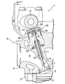
図1は,エンジンとしてのDOHC型エンジン1の排気側を示しており,そのエンジン本体2はシリンダブロック3と,そのシリンダブロック3に結合されたシリンダヘッド4とよりなる。シリンダブロック3にピストン5が摺動可能に嵌合され,ピストン5とシリンダヘッド4との間に燃焼室6が形成される。シリンダヘッド4には,燃焼室6の天井面に開口する排気弁口7と,その排気弁口7に通じる排気ポート8が設けられている。排気弁口7は排気弁9により開閉され,そのステム10は,シリンダヘッド4に圧入されたガイド筒11に摺動自在に嵌合される。
FIG. 1 shows an exhaust side of a DOHC type engine 1 as an engine. The
ガイド筒11から突出したステム10の端部に,二つ割りコッタ12を介してスプリングリテーナ13が固定されており,このスプリングリテーナ13と,それと対向するようにシリンダヘッド4に支持されたばね受部材14との間に,ステム10を囲繞するコイル状弁ばね15が圧縮状態で設けられている。これにより排気弁9が常時閉弁方向に付勢される。
A
バルブリフタ16は,弁ばね15の上部,スプリングリテーナ13およびステム10の上部をインナーシムaを介して覆うと共に動弁カム17およびシリンダヘッド4のガイド孔18とそれぞれ摺動関係にある。この場合,動弁カム17はねずみ鋳鉄,合金鋳鉄,鋼(炭素鋼,Cr鋼,Cr−Mo鋼)等より構成され,またシリンダヘッド4,つまりガイド孔18の孔壁はAl合金より構成される。以上のように排気側についてのみ説明したが,上記構成は吸気側についても同様である。
The
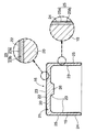
図2に明示するように,バルブリフタ16は,シリンダヘッド4のガイド孔17内に挿入される筒状部(実施例では円筒形)19およびその筒状部19の一端を閉鎖する端壁状部20を持ち,且つチタン合金よりなる。バルブリフタ16が動弁カム17と摺動する摺動面,つまりカム摺動面22には,端壁状部20外表面に形成された第1の酸化膜23aと,第1の酸化膜と素材間に形成される第1の拡散層23bとにより構成される第1の硬化層が形成される。バルブリフタ16がシリンダヘッド4のガイド孔18と摺動する摺動面,つまり孔壁摺動面24には,筒状部19外周面に形成された第2の酸化膜25aと,第2の酸化膜と素材間に形成される第2の拡散層25bとにより構成される第2の硬化層が形成される。実施例ではバルブリフタ16の内面全体が第1の硬化層23に形成されており,端壁状部20内面に在る中央突起26の端面が第1の硬化層23を介してインナーシムaに当接する。
As clearly shown in FIG. 2, the
第1の硬化層23のビッカース硬さH1 と第2の硬化層25のビッカース硬さH2 との間にはH1 >H2 の関係を成立させてある。即ち,第1の硬化層23のビッカース硬さH1 は500HV0.1<H1 ≦800HV0.1であり,一方,第2の硬化層25のビッカース硬さH2 は300HV0.1≦H2 ≦500HV0.1に設定される。
The Vickers hardness H 1 of the first hardened
バルブリフタ16において,動弁カム17と摺動するカム摺動面22に要求される摺動条件はガイド孔18と摺動する孔壁摺動面24に要求される摺動条件よりも厳しい。そこで,動弁カム17に対応する第1の硬化層23のビッカース硬さH1 を,ガイド孔18に対応する第2の硬化層25のビッカース硬さH2 よりも高く設定し,また両ビッカース硬さH1 ,H2 を前記のように特定したものであり,これにより良好な耐摩耗性を持つと共に相手材である動弁カム17およびガイド孔18の孔壁に対する攻撃性が低い,つまり優れた摺動特性を有する,軽量で,且つ高強度なチタン合金製バルブリフタ16を提供することができる。
In the
このようなバルブリフタ16は,図3,図4に示す各工程を経て製造される。
Such a
(a)工程
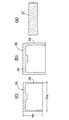
図3(a)に示すように,チタン合金よりなる丸棒から円盤形ビレット27を切出し,次いでそのビレット27に潤滑処理を施す。
(A) Process As shown to Fig.3 (a), the disk-shaped
(b)工程
ビレット27を鍛造温度Tfに加熱し,次いでそのビレット27に温間鍛造を施して,図3(b)に示すバルブリフタ本体用素材28を得る。その素材28は,シリンダヘッド4のガイド孔18内に挿入される筒部29およびその筒部29の一端を閉鎖して動弁カム17と対向する端壁部30を持つ。この場合,鍛造温度Tfは300℃≦Tf≦600℃に設定される。鍛造温度TfがTf<300℃では変形抵抗が高く,金型の負荷が大きい。一方,Tf>600℃では加熱中に表面に酸化膜が生じ,鍛造時にこの酸化膜に発生する亀裂を起点に割れが生じやすくなる。
(B) Process The
(c)工程
バルブリフタ本体用素材28の筒部29外周面,端壁部30外面および筒部29の環状端面に機械加工を施して,図3(c)に示すように1次酸化処理にて生じる歪みを除去するのに十分な削り代を形成すべく,バルブリフタ完成寸法より外径を大きく設定した所定寸法に仕上げられたバルブリフタ本体用素材28を製作し,次いでそのバルブリフタ本体用素材28に洗浄処理を施す。
(C) Process Machining is performed on the outer peripheral surface of the
(d)工程
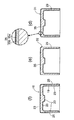
バルブリフタ本体用素材28を大気雰囲気下の加熱炉内に設置して,その素材28に,大気中にて加熱温度T1 をT1 ≧650℃に設定した1次酸化処理を施し,図4(d)に示すように,バルブリフタ素材28全面に1次酸化処理後の硬化層35を形成された第1中間体31を得る。この場合,1次酸化処理後の硬化層35は素材28の全面に形成された酸化膜35aと,酸化膜35aと素材28間に形成された拡散層35bとにより構成される。
(D) Process The valve
(e)工程
第1中間体31をセンタレス研削装置に設置し,次いでその装置を作動させ,図4(e)に示すように,筒部29外周面側に存する削り代分だけ研削して第2中間体32を製作し,その後第2中間体32に洗浄処理を施す。
(E) Process The first
(f)工程
第2中間体32を前記の大気雰囲気下の加熱炉内に設置して,その第2中間体32に,大気中にて,加熱温度T2 を400℃<T2 <650℃に設定した2次酸化処理を施し,図4(f)に示すように,カム摺動面22およびバルブリフタ16の内面全体に第1の硬化層23を形成し,筒部29外周面に第2の硬化層25を形成する。第1の硬化層23は,1次酸化処理および2次酸化処理により形成された第1の酸化膜23aと,第1の酸化膜と素材間に形成される第1の拡散層23bとにより構成される。また,第2の硬化層25は2次酸化処理により形成された第2の酸化膜25aと,第2の酸化膜と素材間に形成される第2の拡散層25bとにより構成される。
Step (f) by installing a second intermediate 32 in a heating furnace of an air atmosphere of the, to the second intermediate 32, in the atmosphere, the heating temperature T 2 400 ℃ <T 2 < 650 ℃ As shown in FIG. 4 (f), the first
前記チタン合金としては,0.30wt%≦Fe≦1.50wt%,0.20wt%≦O≦0.70wt%および不可避不純物を含む残部Tiよりなるものが好適である。 The titanium alloy is preferably made of 0.30 wt% ≦ Fe ≦ 1.50 wt%, 0.20 wt% ≦ O ≦ 0.70 wt% and the balance Ti containing inevitable impurities.
以下,具体例について説明する。 Specific examples will be described below.
〔A〕バルブリフタ16の製造
(a)〜(c)工程:0.96wt%Fe,0.28wt%Oおよび不可避不純物を含む残部Tiよりなるチタン合金より構成された外径Da 26mm,高さHc 21mmのバルブリフタ素材28を製作.
(d)工程…1次酸化処理;加熱温度T1 ≧650℃.
(e)工程…センタレス研削条件:筒部29外周面側に存する削り代分だけ研削.
(f)工程…2次酸化処理:加熱温度T2 400℃<T2 <650℃.
〔B〕ビッカース硬さおよびひずみの測定
バルブリフタ16の各例について,第1および第2の硬化層23,25,つまりカム摺動面22および孔壁摺動面24のビッカース硬さ(HV0.1,試験荷重:0.9807N)H1 ,H2 をそれぞれ測定し,また第2の硬化層25を有する筒状部19のひずみ(第2の硬化層25外周面の真円度)Δrを測定した。
[A] Manufacture of
(D) Step: primary oxidation treatment; heating temperature T 1 ≧ 650 ° C.
(E) Process: Centerless grinding condition: Grinding for the machining allowance existing on the outer peripheral surface of the
(F) Process ... Secondary oxidation treatment: Heating temperature T 2 400 ° C. <T 2 <650 ° C.
[B] Measurement of Vickers Hardness and Strain For each example of the
〔C〕モータリングテスト
バルブリフタ16の各例を,図1のDOHC型エンジン1と同様の構造を有する,1000cc,4気筒エンジンに組込んで,低粘度の劣化エンジンオイルを用いて摩耗評価モードでモータリングテストを行い,バルブリフタ16のカム摺動面22および孔壁摺動面24における摩耗の有無ならびに相手部材である動弁カム17およびガイド孔18孔壁における摩耗の有無を調べた。この場合,動弁カム17はカム山部を鋳造時に冷し金により硬化させた鋳鉄(JIS FC300)より構成され,またシリンダヘッド4,つまりガイド孔18の孔壁はAl合金(JIS AC2B相当)より構成された。
[C] Motoring test Each example of the
〔D−1〕バルブリフタの例(1)〜(6)について
表1は,1次酸化処理条件とセンタレス研削前の筒部29のひずみΔrを示す。
[D-1] Examples of valve lifters (1) to (6) Table 1 shows primary oxidation conditions and strain Δr of the

この〔D−1〕においては,1次酸化処理の加熱温度T1 を例(1)〜(6)について変化させる一方,加熱時間t1 を例(1)〜(6)について一定とした。 In the [D-1], while changing an example the heating temperature T 1 of the primary oxidation process (1) to (6), the heating time t 1 was constant for Example (1) to (6).
表2は,2次酸化処理条件と2次酸化処理後の筒状部19のひずみΔrを示す。
Table 2 shows the secondary oxidation treatment conditions and the strain Δr of the
この〔D−1〕においては,例(1)〜(6)について2次酸化処理の加熱温度T2 および加熱時間t2 をそれぞれ一定とした。この2次酸化処理後の筒状部19のひずみΔrはΔr≦10μmであれば実用上問題は無い。
In [D-1], the heating temperature T 2 and the heating time t 2 of the secondary oxidation treatment were kept constant for Examples (1) to (6). If the strain Δr of the
表3は,カム摺動面22および孔壁摺動面24のビッカース硬さH1 ,H2 と,モータリングテストにおけるカム摺動面22および孔壁摺動面24ならびに相手部材である動弁カム17およびガイド孔18孔壁の摩耗の有無を示す。
Table 3 shows the Vickers hardnesses H 1 and H 2 of the
表3から明らかなように,1次酸化処理において,加熱時間t1 を一定にすると共に加熱温度T1 を漸次上昇させると,第1の硬化層23のビッカース硬さH1 を漸次高くすることができる。また例(1)〜(5)のごとく,第1の硬化層23のビッカース硬さH1 を500HV0.1<H1 ≦800HV0.1に,一方,第2の硬化層25のビッカース硬さH2 を300HV0.1≦H2 ≦500HV0.1にそれぞれ設定すると,カム摺動面22および孔壁摺動面24の耐摩耗性を向上させると共に動弁カム17およびガイド孔18孔壁に対する攻撃性を低減することができる。
As is apparent from Table 3, in the primary oxidation treatment, when the heating time t 1 is made constant and the heating temperature T 1 is gradually increased, the Vickers hardness H 1 of the first
例(6)においては第1の硬化層23のビッカース硬さH1 がH1 >800HV0.1であることから,その硬化層23がモータリングテスト中に剥離した。この場合,動弁カム17の摩耗量は測定しなかった。
In Example (6), since the Vickers hardness H 1 of the first cured
〔D−2〕バルブリフタの例(7)〜(14)について
表4は,1次および2次酸化処理条件と2次酸化処理後の筒状部19のひずみΔrを示す。
[D-2] Examples of Valve Lifter (7) to (14) Table 4 shows primary and secondary oxidation treatment conditions and strain Δr of the
この〔D−2〕においては,1次酸化処理の加熱温度T1 を例(7)〜(14)について変化させる一方,加熱時間t1 を例(7)〜(14)について一定とし,且つ〔D−1〕の場合よりも長くした。2次酸化処理の加熱温度T2 および加熱時間t2 はそれぞれ一定とした。ただし,加熱温度T2 は〔D−1〕の場合よりも高い。 In [D-2], the heating temperature T 1 of the primary oxidation treatment is changed for the examples (7) to (14), while the heating time t 1 is constant for the examples (7) to (14), and The length was longer than in the case of [D-1]. Heating temperature T 2 and the heating time t 2 of the secondary oxidation treatment was respectively constant. However, the heating temperature T 2 is higher than that of [D-1].
表5は,カム摺動面22および孔壁摺動面24のビッカース硬さH1 ,H2 と,モータリングテストにおけるカム摺動面22および孔壁摺動面24ならびに相手部材である動弁カム17およびガイド孔18孔壁の摩耗の有無を示す。
Table 5 shows the Vickers hardnesses H 1 and H 2 of the
表5から明らかなように,1次加熱処理の加熱時間t1 を〔D−1〕の場合よりも長くすると,同一加熱温度T1 において第1の硬化層23のビッカース硬さH1 を高くすることができる。また2次加熱処理の加熱温度T2 を〔D−1〕の場合よりも高くすると,同一加熱時間t2 において第2の硬化層25のビッカース硬さH2 を高くすることができる。さらに,例(8)〜(13)のごとく,第1の硬化層23のビッカース硬さH1 を500HV0.1<H1 ≦800HV0.1に,一方,第2の硬化層25のビッカース硬さH2 を300HV0.1≦H2 ≦500HV0.1にそれぞれ設定すると,カム摺動面22および孔壁摺動面24の耐摩耗性を向上させると共に動弁カム17およびガイド孔18孔壁に対する攻撃性を低減することができる。
As is apparent from Table 5, when the heating time t 1 of the primary heat treatment is made longer than in the case of [D-1], the Vickers hardness H 1 of the first
例(7)においては第1の硬化層23のビッカース硬さH1 がH1 ≦500HV0.1であることから,その硬化層23がモータリングテスト中に摩耗した。この場合,動弁カム17の摩耗量は測定しなかった。また例(14)においては第1の硬化層23のビッカース硬さH1 がH1 >800HV0.1であることから,その硬化層23がモータリングテスト中に剥離した。この場合,動弁カム17の摩耗量は測定しなかった。
In Example (7), since the Vickers hardness H 1 of the first cured
〔D−3〕バルブリフタの例(15)〜(20)について
表6は,1次および2次酸化処理条件と2次酸化処理後の筒状部19のひずみΔrを示す。〔D−3〕には例(5)に関するデータも掲載されている。
[D-3] Examples of Valve Lifter (15) to (20) Table 6 shows primary and secondary oxidation treatment conditions and strain Δr of the
この〔D−3〕においては,例(15)〜(20)について1次酸化処理の加熱温度T1 および加熱時間t1 をそれぞれ一定とした。それら温度T1 および時間t1 は例(5)の場合と同じである。2次酸化処理の加熱温度T2 は例(15)〜(20)について変化させる一方,加熱時間t2 は例(15)〜(20)について一定とした。その時間t2 は例(5)の場合と同じである。 In this [D-3], the heating temperature T 1 and the heating time t 1 of the primary oxidation treatment were kept constant for Examples (15) to (20). These temperature T 1 and time t 1 are the same as in the case of Example (5). Heating temperature T 2 of the second oxidation treatment while varying the example (15) - (20), the heating time t 2 was fixed for example (15) - (20). The time t 2 is the same as in the case of the example (5).
表7は,カム摺動面22および孔壁摺動面24のビッカース硬さH1 ,H2 と,モータリングテストにおけるカム摺動面22および孔壁摺動面24ならびに相手部材である動弁カム17およびガイド孔18孔壁の摩耗の有無を示す。
Table 7 shows the Vickers hardness H 1 and H 2 of the
表7から明らかなように,2次酸化処理において,加熱時間t2 を一定にすると共に加熱温度T2 を漸次上昇させると,第2の硬化層25のビッカース硬さH2 を漸次高くすることができる。また例(5),(16),(17)のごとく,第1の硬化層23のビッカース硬さH1 を500HV0.1<H1 ≦800HV0.1に,一方,第2の硬化層25のビッカース硬さH2 を300HV0.1≦H2 ≦500HV0.1にそれぞれ設定すると,カム摺動面22および孔壁摺動面24の耐摩耗性を向上させると共に動弁カム17およびガイド孔18孔壁に対する攻撃性を低減することができる。
As is apparent from Table 7, in the secondary oxidation treatment, when the heating time t 2 is kept constant and the heating temperature T 2 is gradually increased, the Vickers hardness H 2 of the second
例(15)においては第2の硬化層25のビッカース硬さH2 がH2 <300HV0.1であることから,その硬化層25がモータリングテスト中に摩耗した。この場合,ガイド孔18孔壁の摩耗量は測定しなかった。また例(18),(19),(20)においては第2の硬化層25のビッカース硬さH2 がH2 >500HV0.1であると共に筒状部19のひずみΔrがΔr>10μであることから,孔壁摺動面24は摩耗しなかったが,ガイド孔18孔壁が摩耗した。
In Example (15), since the Vickers hardness H 2 of the second
〔D−4〕バルブリフタの例(21)〜(24)について
表8は,1次および2次酸化処理条件と2次酸化処理後の筒状部19のひずみΔrを示す。この〔D−4〕には例(16)に関するデータも掲載されている。
[D-4] Examples of Valve Lifter (21) to (24) Table 8 shows the primary and secondary oxidation conditions and the strain Δr of the
この〔D−4〕においては,例(21)〜(24)について1次酸化処理の加熱温度T1 および加熱時間t1 をそれぞれ一定とした。それら温度T1 および時間t1 は例(16)の場合と同じである。2次酸化処理の加熱温度T2 を例(22)〜(24)について一定にする一方,加熱時間t2 を例(22)〜(24)について変化させた。その温度T2 は例(16)の場合と同じである。例(21)の場合は,加熱温度T2 が例(22)等に比べて低く,加熱時間t2 は長く,例(23)と同じである。 In [D-4], the heating temperature T 1 and the heating time t 1 of the primary oxidation treatment were kept constant for Examples (21) to (24). These temperature T 1 and time t 1 are the same as in the case of Example (16). While constant for example the heating temperature T 2 of the second oxidation process (22) to (24), and the heating time t 2 is changed for example (22) - (24). The temperature T 2 is the same as in Example (16). In the case of Example (21), the heating temperature T 2 is lower than that in Example (22) and the heating time t 2 is long, which is the same as in Example (23).
表9は,カム摺動面22および孔壁摺動面24のビッカース硬さと,モータリングテストにおけるカム摺動面22および孔壁摺動面24ならびに相手部材である動弁カム17およびガイド孔18孔壁の摩耗の有無を示す。
Table 9 shows the Vickers hardness of the
表9から明らかなように,例(16),(22)〜(24)のごとく,第2酸化処理における加熱温度T2 を一定にすると共に加熱時間t2 を漸次長くすると,第2の硬化層25のビッカース硬さH2 を漸次高くすることができる。例(21)の場合は,加熱温度T2 が低いので,加熱時間t2 を長くしても第2の硬化層25のビッカース硬さH2 は高くならない。また例(16),(22)〜(24)のごとく,第1の硬化層23のビッカース硬さH1 を500HV0.1<H1 ≦800HV0.1に,一方,第2の硬化層25のビッカース硬さH2 を300HV0.1≦H2 ≦500HV0.1にそれぞれ設定すると,カム摺動面22および孔壁摺動面24の耐摩耗性を向上させると共に動弁カム17およびガイド孔18孔壁に対する攻撃性を低減することができる。
As is clear from Table 9, as shown in Examples (16) and (22) to (24), when the heating temperature T 2 in the second oxidation treatment is made constant and the heating time t 2 is gradually increased, the second curing is performed. The Vickers hardness H 2 of the layer 25 can be gradually increased. Examples case (21), the heating temperature T 2 is low, the Vickers hardness of H 2 second hardened
例(21)においては第2の硬化層25のビッカース硬さH2 がH2 <300HV0.1であることから,その硬化層25がモータリングテスト中に摩耗した。この場合,ガイド孔18孔壁の摩耗量は測定しなかった。
In Example (21), since the Vickers hardness H 2 of the second
次に,ビレット27の材質,つまりチタン合金の組成と,温間鍛造性およびカム摺動面の耐摩耗性との関係等を調べるため,各種材質のビレット27を用いて前記同様の方法で各種バルブリフタ16を製造した。ただし,1次酸化処理の加熱温度T1 は750℃に,また加熱時間t1 は3時間にそれぞれ設定され,一方,2次酸化処理の加熱温度T2 は600℃に,また加熱時間t2 は18時間にそれぞれ設定された。
Next, in order to investigate the relationship between the material of the
表10はビレット27の材質と,温間鍛造性およびカム摺動面の耐摩耗性との関係を示す。
Table 10 shows the relationship between the material of the
表10から明らかなように,ビレット27の例(3)〜(10)のごとく,Fe含有量を0.30wt%≦Fe≦1.50wt%に,またO含有量を0.20wt%≦0≦0.70wt%に設定すると,良好な温間鍛造性および耐摩耗性が得られる。ビレットの例(12)はO含有量が0<0.20wt%であることから耐摩耗性が低下する。
As is apparent from Table 10, as in the cases (3) to (10) of the
2……………エンジン本体
16…………バルブリフタ
17…………動弁カム
18…………ガイド孔
19…………筒状部
20…………端壁状部
22…………カム摺動面
23…………第1の硬化層
24…………孔壁摺動面
25…………第2の硬化層
28…………バルブリフタ素材
29…………筒部
30…………端壁部
31…………第1中間体
32…………第2中間体
2 …………
Claims (5)
Priority Applications (1)
| Application Number | Priority Date | Filing Date | Title |
|---|---|---|---|
| JP2004107170A JP4292099B2 (en) | 2004-03-31 | 2004-03-31 | Titanium alloy valve lifter for engine and manufacturing method thereof |
Applications Claiming Priority (1)
| Application Number | Priority Date | Filing Date | Title |
|---|---|---|---|
| JP2004107170A JP4292099B2 (en) | 2004-03-31 | 2004-03-31 | Titanium alloy valve lifter for engine and manufacturing method thereof |
Publications (2)
| Publication Number | Publication Date |
|---|---|
| JP2005291085A true JP2005291085A (en) | 2005-10-20 |
| JP4292099B2 JP4292099B2 (en) | 2009-07-08 |
Family
ID=35324302
Family Applications (1)
| Application Number | Title | Priority Date | Filing Date |
|---|---|---|---|
| JP2004107170A Expired - Fee Related JP4292099B2 (en) | 2004-03-31 | 2004-03-31 | Titanium alloy valve lifter for engine and manufacturing method thereof |
Country Status (1)
| Country | Link |
|---|---|
| JP (1) | JP4292099B2 (en) |
-
2004
- 2004-03-31 JP JP2004107170A patent/JP4292099B2/en not_active Expired - Fee Related
Also Published As
| Publication number | Publication date |
|---|---|
| JP4292099B2 (en) | 2009-07-08 |
Similar Documents
| Publication | Publication Date | Title |
|---|---|---|
| EP0091097A1 (en) | Engine valve and method of producing the same | |
| CN101548120B (en) | Valve device | |
| JP5311918B2 (en) | Spring retainer and spring system | |
| US20070227626A1 (en) | Valve train component for an internal combustion engine, and method of making same | |
| WO2005042931A1 (en) | Method of manufacturing camshaft, camshaft, and cam lobe material used for the camshaft | |
| JP4116983B2 (en) | Titanium valve spring retainer | |
| JP4292099B2 (en) | Titanium alloy valve lifter for engine and manufacturing method thereof | |
| US7628870B2 (en) | Heat treated valve guide and method of making | |
| JPH0821216A (en) | Engine valve | |
| JP5060083B2 (en) | Piston ring manufacturing method | |
| US7600499B2 (en) | Titanium alloy valve lifter | |
| US7308760B2 (en) | Method of making a valve lifter | |
| JP4208797B2 (en) | Rolling bearings used for rocker arms | |
| US5918367A (en) | Method of producing valve lifter | |
| EP0711904B1 (en) | Sliding part and a method of producing thereof | |
| JPH0261308A (en) | Manufacture of locker arm | |
| JP3795013B2 (en) | Valve lifter for valve operating mechanism of internal combustion engine | |
| Maki et al. | Development of a high-performance TiA1 exhaust valve | |
| JP4870922B2 (en) | Connecting rod, engine, motor vehicle and manufacturing method of connecting rod | |
| JP2008215157A (en) | Engine valve | |
| JP2001329345A (en) | Piston ring material and piston ring for internal combustion engine having self-lubricity | |
| JPH09256821A (en) | Engine valve | |
| JPH11201136A (en) | Automotive internal combustion engine parts | |
| JPH09217611A (en) | Valve mechanism for internal combustion engine | |
| JPH09195729A (en) | Titanium alloy poppet valve |
Legal Events
| Date | Code | Title | Description |
|---|---|---|---|
| A621 | Written request for application examination |
Free format text: JAPANESE INTERMEDIATE CODE: A621 Effective date: 20061129 |
|
| A977 | Report on retrieval |
Free format text: JAPANESE INTERMEDIATE CODE: A971007 Effective date: 20080716 |
|
| A131 | Notification of reasons for refusal |
Free format text: JAPANESE INTERMEDIATE CODE: A131 Effective date: 20080917 |
|
| A521 | Written amendment |
Free format text: JAPANESE INTERMEDIATE CODE: A523 Effective date: 20081117 |
|
| TRDD | Decision of grant or rejection written | ||
| A01 | Written decision to grant a patent or to grant a registration (utility model) |
Free format text: JAPANESE INTERMEDIATE CODE: A01 Effective date: 20090331 |
|
| A01 | Written decision to grant a patent or to grant a registration (utility model) |
Free format text: JAPANESE INTERMEDIATE CODE: A01 |
|
| A61 | First payment of annual fees (during grant procedure) |
Free format text: JAPANESE INTERMEDIATE CODE: A61 Effective date: 20090406 |
|
| R150 | Certificate of patent or registration of utility model |
Free format text: JAPANESE INTERMEDIATE CODE: R150 |
|
| FPAY | Renewal fee payment (event date is renewal date of database) |
Free format text: PAYMENT UNTIL: 20120410 Year of fee payment: 3 |
|
| FPAY | Renewal fee payment (event date is renewal date of database) |
Free format text: PAYMENT UNTIL: 20130410 Year of fee payment: 4 |
|
| FPAY | Renewal fee payment (event date is renewal date of database) |
Free format text: PAYMENT UNTIL: 20130410 Year of fee payment: 4 |
|
| FPAY | Renewal fee payment (event date is renewal date of database) |
Free format text: PAYMENT UNTIL: 20140410 Year of fee payment: 5 |
|
| LAPS | Cancellation because of no payment of annual fees |