JP2005291044A - Multi-cylinder engine with turbo type supercharger - Google Patents
Multi-cylinder engine with turbo type supercharger Download PDFInfo
- Publication number
- JP2005291044A JP2005291044A JP2004105367A JP2004105367A JP2005291044A JP 2005291044 A JP2005291044 A JP 2005291044A JP 2004105367 A JP2004105367 A JP 2004105367A JP 2004105367 A JP2004105367 A JP 2004105367A JP 2005291044 A JP2005291044 A JP 2005291044A
- Authority
- JP
- Japan
- Prior art keywords
- cylinder
- exhaust
- cylinders
- engine
- turbocharger
- Prior art date
- Legal status (The legal status is an assumption and is not a legal conclusion. Google has not performed a legal analysis and makes no representation as to the accuracy of the status listed.)
- Granted
Links
- 239000007789 gas Substances 0.000 claims description 99
- 239000003054 catalyst Substances 0.000 claims description 31
- 238000004891 communication Methods 0.000 claims description 27
- 238000002485 combustion reaction Methods 0.000 claims description 23
- 230000007246 mechanism Effects 0.000 claims description 17
- 238000011144 upstream manufacturing Methods 0.000 claims description 10
- 229910052751 metal Inorganic materials 0.000 claims description 4
- 239000002184 metal Substances 0.000 claims description 4
- 239000000446 fuel Substances 0.000 abstract description 122
- 238000004904 shortening Methods 0.000 abstract description 2
- MWUXSHHQAYIFBG-UHFFFAOYSA-N nitrogen oxide Inorganic materials O=[N] MWUXSHHQAYIFBG-UHFFFAOYSA-N 0.000 description 54
- 238000010521 absorption reaction Methods 0.000 description 23
- 238000002347 injection Methods 0.000 description 21
- 239000007924 injection Substances 0.000 description 21
- 230000000694 effects Effects 0.000 description 16
- 238000000034 method Methods 0.000 description 11
- 230000002829 reductive effect Effects 0.000 description 11
- 230000002000 scavenging effect Effects 0.000 description 11
- 238000001514 detection method Methods 0.000 description 10
- 230000036961 partial effect Effects 0.000 description 7
- 230000001133 acceleration Effects 0.000 description 6
- 230000008569 process Effects 0.000 description 6
- 230000000979 retarding effect Effects 0.000 description 6
- 230000035939 shock Effects 0.000 description 5
- 230000000052 comparative effect Effects 0.000 description 4
- 230000006866 deterioration Effects 0.000 description 4
- 230000008859 change Effects 0.000 description 3
- 238000002474 experimental method Methods 0.000 description 3
- 230000033001 locomotion Effects 0.000 description 3
- 238000000926 separation method Methods 0.000 description 3
- 230000007704 transition Effects 0.000 description 3
- 230000004913 activation Effects 0.000 description 2
- 238000010586 diagram Methods 0.000 description 2
- 238000010304 firing Methods 0.000 description 2
- 230000006872 improvement Effects 0.000 description 2
- 229910000510 noble metal Inorganic materials 0.000 description 2
- 238000005086 pumping Methods 0.000 description 2
- 230000004044 response Effects 0.000 description 2
- 230000004043 responsiveness Effects 0.000 description 2
- 239000002699 waste material Substances 0.000 description 2
- UGFAIRIUMAVXCW-UHFFFAOYSA-N Carbon monoxide Chemical compound [O+]#[C-] UGFAIRIUMAVXCW-UHFFFAOYSA-N 0.000 description 1
- 102100023600 Fibroblast growth factor receptor 2 Human genes 0.000 description 1
- 101000827688 Homo sapiens Fibroblast growth factor receptor 2 Proteins 0.000 description 1
- 101100445369 Solanum lycopersicum EOT1 gene Proteins 0.000 description 1
- 239000002250 absorbent Substances 0.000 description 1
- 230000002745 absorbent Effects 0.000 description 1
- 239000006096 absorbing agent Substances 0.000 description 1
- 229910052784 alkaline earth metal Inorganic materials 0.000 description 1
- 150000001342 alkaline earth metals Chemical class 0.000 description 1
- QVGXLLKOCUKJST-UHFFFAOYSA-N atomic oxygen Chemical compound [O] QVGXLLKOCUKJST-UHFFFAOYSA-N 0.000 description 1
- 230000002238 attenuated effect Effects 0.000 description 1
- 230000005540 biological transmission Effects 0.000 description 1
- 229910002091 carbon monoxide Inorganic materials 0.000 description 1
- 238000006243 chemical reaction Methods 0.000 description 1
- 230000006835 compression Effects 0.000 description 1
- 238000007906 compression Methods 0.000 description 1
- 238000001816 cooling Methods 0.000 description 1
- 239000000498 cooling water Substances 0.000 description 1
- JEIPFZHSYJVQDO-UHFFFAOYSA-N ferric oxide Chemical compound O=[Fe]O[Fe]=O JEIPFZHSYJVQDO-UHFFFAOYSA-N 0.000 description 1
- 229930195733 hydrocarbon Natural products 0.000 description 1
- 150000002430 hydrocarbons Chemical class 0.000 description 1
- 230000002401 inhibitory effect Effects 0.000 description 1
- 230000005764 inhibitory process Effects 0.000 description 1
- 239000000203 mixture Substances 0.000 description 1
- 239000001301 oxygen Substances 0.000 description 1
- 229910052760 oxygen Inorganic materials 0.000 description 1
- 230000009467 reduction Effects 0.000 description 1
- 238000004088 simulation Methods 0.000 description 1
- 238000010792 warming Methods 0.000 description 1
Images

Classifications
-
- Y—GENERAL TAGGING OF NEW TECHNOLOGICAL DEVELOPMENTS; GENERAL TAGGING OF CROSS-SECTIONAL TECHNOLOGIES SPANNING OVER SEVERAL SECTIONS OF THE IPC; TECHNICAL SUBJECTS COVERED BY FORMER USPC CROSS-REFERENCE ART COLLECTIONS [XRACs] AND DIGESTS
- Y02—TECHNOLOGIES OR APPLICATIONS FOR MITIGATION OR ADAPTATION AGAINST CLIMATE CHANGE
- Y02T—CLIMATE CHANGE MITIGATION TECHNOLOGIES RELATED TO TRANSPORTATION
- Y02T10/00—Road transport of goods or passengers
- Y02T10/10—Internal combustion engine [ICE] based vehicles
- Y02T10/12—Improving ICE efficiencies
Landscapes
- Supercharger (AREA)
- Output Control And Ontrol Of Special Type Engine (AREA)
Abstract
Description
本発明は、自動車に搭載されるターボ式過給機付きのエンジンに関し、特に、当該エンジンの高出力化を図る技術に属す。 The present invention relates to an engine with a turbocharger mounted on an automobile, and particularly belongs to a technique for increasing the output of the engine.
従来、ターボ式過給機を備えたエンジンは知られており、これにより、排気ガスを利用して吸気を過給させ、こうした過給吸気をエンジンの気筒に供給することで、吸気充填量を増大させてエンジン出力を高出力化することが、一般的に行なわれている。
また、例えば、下記の特許文献1のように、ターボ式過給機を備えたエンジンにおいて、エンジンの全気筒の内、一部の気筒である一方側気筒の排気弁に接続されるとともに、ターボ式過給機の排気タービンを設置した過給排気通路(上述の特許文献1の「駆動通路」に相当)と、残りの気筒である他方側気筒の排気弁に接続されるとともに、ターボ式過給機の排気タービンを設置させない非過給排気通路(上述の特許文献1の「放出通路」に相当)とを備えたエンジンは公知である。
Conventionally, an engine equipped with a turbocharger has been known, and by using this, exhaust gas is used to supercharge intake air, and this supercharged intake air is supplied to the engine cylinder, thereby reducing the intake charge amount. Increasing the engine output by increasing it is generally performed.
Further, for example, as in
ところで、上述のようなターボ式過給機付きエンジンにおいては、一方側気筒から排出される排気ガスの運動エネルギーのみによってターボ式過給機のタービンを回転させて、全気筒に供給される吸気を十分に過給させる必要がある。過給が不十分であると、特に、エンジン回転数が低い低速運転時において出力低下が発生したり、あるいは、低速運転からの加速時において、加速性が悪化するといった問題が生じることになる。 By the way, in the turbocharged engine as described above, the turbine of the turbocharger is rotated only by the kinetic energy of the exhaust gas discharged from the one side cylinder, and the intake air supplied to all the cylinders is It needs to be supercharged sufficiently. Insufficient supercharging may cause problems such as a decrease in output during low-speed operation with a low engine speed, or deterioration in acceleration during acceleration from low-speed operation.
本発明は、以上のような課題に勘案してなされたもので、その目的は、ターボ式過給機付き多気筒エンジンにおいて、ターボ式過給機が設置された過給排気通路に接続される全ての一方側気筒において、1気筒における排気弁からターボ式過給機までの過給排気通路の長さを短くすることで、一方側気筒及び他方側気筒の全気筒に吸気を供給する際の過給効率を増大させて、出力向上を図ることにある。 The present invention has been made in consideration of the above-described problems, and its purpose is connected to a supercharged exhaust passage in which a turbocharger is installed in a multi-cylinder engine with a turbocharger. In all the one-side cylinders, when the intake air is supplied to all cylinders of the one-side cylinder and the other-side cylinder by shortening the length of the supercharged exhaust passage from the exhaust valve to the turbocharger in one cylinder. The purpose is to improve the output by increasing the supercharging efficiency.
このような目的を達成するために、本発明の請求項1記載の発明においては、エンジンの複数の気筒と、全気筒の内、着火順序が連続しない複数の一方側気筒の排気弁に接続されるとともに、該複数の気筒から排出される排気ガスを流通させることにより全気筒に供給される吸気を過給可能なターボ式過給機が設置された過給排気通路と、全気筒の内、着火順序が連続しない残りの複数の他方側気筒における排気弁に接続されるとともに、該ターボ式過給機が設置されない非過給排気通路とを備えた自動車に搭載されるターボ式過給機付き多気筒エンジンにおいて、複数の上記一方側気筒は、略直列的に隣接配置されるとともに、上記過給排気通路は、全ての該一方側気筒において、1気筒における上記排気弁から上記ターボ式過給機までの排気ガスが流れる経路の長さが、所定値以下となるよう形成されることを特徴とする。
このような構成により、ターボ式過給機と接続される全ての一方側気筒において、1気筒における排気弁からターボ式過給機までの排気ガスが流れる経路の長さが、所定値以下に短く設定されることになる。これにより、一方側気筒によるターボ式過給機の過給を増大することができるため、一方側気筒及び他方側気筒を合わせた全気筒に対する過給効率を増大させて、エンジンの出力向上を図ることができる。
また、この場合、一方側気筒は、互いに着火順序が連続しない気筒から成るため、各気筒において排気ガスが排出されやすくなり、過給を増大させつつ、掃気性も向上できる。更に、一方側気筒は、略直列的に隣接配置されているため、以上のような過給効率と掃気性との向上が図れるエンジンを、簡素化された構成で実現できる。
In order to achieve such an object, in the invention according to
With such a configuration, in all the one-side cylinders connected to the turbocharger, the length of the path through which exhaust gas from the exhaust valve to the turbocharger in one cylinder flows is shorter than a predetermined value. Will be set. As a result, the turbocharging of the turbocharger by the one side cylinder can be increased, so that the supercharging efficiency for all the cylinders including the one side cylinder and the other side cylinder is increased to improve the engine output. be able to.
Further, in this case, since the one-side cylinder is composed of cylinders whose ignition order is not continuous with each other, the exhaust gas is easily discharged from each cylinder, and the scavenging performance can be improved while increasing the supercharging. Furthermore, since the one-side cylinders are adjacently arranged in series, an engine capable of improving the supercharging efficiency and scavenging performance as described above can be realized with a simplified configuration.
請求項2記載の発明は、請求項1において、少なくとも上記一方側気筒の上記排気弁の開弁開始時期を調整可能であり、該開弁開始時期を、エンジン回転数が低い時には、エンジン回転数が高い時に比べて遅角するよう調整する排気バルブタイミング機構を備えることを特徴とする。
本出願の発明者は、一方側気筒の1気筒における排気弁からターボ式過給機までの排気ガスが流れる経路の長さを、所定値以下に短く設定した場合にのみ、その気筒の排気弁の開弁開始時期を遅角させることによる過給の大幅な増大が得られることを発見した。
従って、請求項2記載の構成により、一方側気筒による過給の増大効果を更に向上させることができ、更なる過給効率化を図ることができる。
According to a second aspect of the present invention, in the first aspect, at least the exhaust valve start timing of the exhaust valve of the one-side cylinder can be adjusted, and when the engine speed is low, An exhaust valve timing mechanism that adjusts so as to be retarded as compared to when the engine is high is provided.
The inventor of the present application only applies the exhaust valve of one cylinder of the one side cylinder when the length of the path through which the exhaust gas flows from the exhaust valve to the turbocharger is set shorter than a predetermined value. It has been found that a significant increase in supercharging can be obtained by retarding the valve opening start time.
Therefore, according to the configuration of the second aspect, the effect of increasing supercharging by the one-side cylinder can be further improved, and further supercharging efficiency can be achieved.
請求項3記載の発明は、請求項1において、上記過給排気通路には、該ターボ式過給機の直ぐ上流において、上記一方側気筒の全気筒の排気ガスを2つの排気ガス流に分離するように、2つの分離排気通路が形成されるとともに、上記ターボ式過給機は、該分離排気通路により分離された2つの排気ガス流が、1つの回転可能なタービンと接触するよう構成されることを特徴とする。
このような構成により、一方側気筒において、例えば、1気筒当たりの排気ガス量が少ない場合であっても、排気ガスを、分離排気通路により排気ガス流の運動エネルギーが大幅に減衰されない状態でターボ式過給機まで供給することができ、広い運転領域で確実に過給効果を得ることが可能となる。
According to a third aspect of the present invention, in the first aspect, in the supercharged exhaust passage, the exhaust gas of all cylinders of the one-side cylinder is separated into two exhaust gas flows immediately upstream of the turbocharger. As described above, two separate exhaust passages are formed, and the turbocharger is configured such that two exhaust gas flows separated by the separate exhaust passages are in contact with one rotatable turbine. It is characterized by that.
With such a configuration, in one side cylinder, for example, even when the amount of exhaust gas per cylinder is small, the exhaust gas is turbocharged in a state where the kinetic energy of the exhaust gas flow is not significantly attenuated by the separated exhaust passage. The turbocharger can be supplied to the turbocharger, and the supercharging effect can be reliably obtained in a wide operation range.
請求項4記載の発明は、請求項3おいて、上記過給排気通路には、2つの該分離排気通路を互いに連通する連通通路が形成されるとともに、該連通通路に、エンジン回転数が低い時に閉弁され、エンジン回転数が高い時に開弁される連通弁が設置されることを特徴とする。
このような構成により、エンジン回転数が高いときには、1気筒当たりの排気ガス量が増大してしまい、ターボ式過給機の排気ガス入り口側で、排気ガスの流れが悪化して、排気ガスが詰まるような状態となり、過給増大が阻害される。
そこで、このような時には、一方側の分離排気通路から他方側の分離排気通路に排気ガスを逃がすことで、一方側の分離排気通路に排気ガスが詰まるような状態を解消しつつ、他方側の分離排気通路も利用して、排気ガス流のエネルギーを効率的に過給生成のエネルギーに変換している。これにより確実に高い過給効果を得ることが可能となる。
According to a fourth aspect of the present invention, in the third aspect, the supercharged exhaust passage is formed with a communication passage that connects the two separated exhaust passages to each other, and the engine speed is low in the communication passage. A communication valve that is sometimes closed and opened when the engine speed is high is provided.
With this configuration, when the engine speed is high, the amount of exhaust gas per cylinder increases, and the flow of exhaust gas deteriorates on the exhaust gas inlet side of the turbocharger. It becomes a clogged state, and supercharging increase is inhibited.
Therefore, in such a case, the exhaust gas is allowed to escape from the separation exhaust passage on one side to the separation exhaust passage on the other side, thereby eliminating the state where the exhaust gas is clogged in the separation exhaust passage on the one side, and A separate exhaust passage is also used to efficiently convert the energy of the exhaust gas flow into energy for supercharging generation. This makes it possible to reliably obtain a high supercharging effect.
請求項5記載の発明は、請求項1おいて、上記非過給排気通路は、上記他方側気筒の各気筒から排出される排気ガスを合流させる合流部を有すとともに、上記過給排気通路は、全ての上記一方側気筒における上記排気弁から上記ターボ過給機までの排気ガスが流れる経路の長さの平均が、全ての該他方側気筒における上記排気弁から該合流部までの排気ガスが流れる経路の長さの平均よりも短くなるよう形成されることを特徴とする。
このような構成により、他方側気筒においては、平均的に排気ガスが流れる経路の長さが長くなるので、他方側気筒間における掃気効果を向上できる。
The invention according to
With such a configuration, in the other cylinder, the length of the path through which the exhaust gas flows is increased on average, so that the scavenging effect between the other cylinders can be improved.
請求項6記載の発明は、請求項1おいて、上記所定値とは、略100mm以下であることを特徴とする。
このような構成により、過給効率をより向上できる。
請求項7記載の発明は、請求項1おいて、上記一方側気筒の一気筒当たりにおいて、ピストンが下死点にある状態での容積を気筒内容積とするとともに、上記過給排気通路において、上記排気弁から上記ターボ式過給機までの容積を排気通路容積とした場合、上記所定値は、該気筒内容積の方が該排気通路容積よりも大きくなるような長さに設定されることを特徴とする。
このような構成により、過給効率をより向上できる。
請求項8記載の発明は、請求項1おいて、エンジンの運転状態が、低回転低負荷状態の時においては、上記一方側気筒のみを燃焼運転させ、上記他方側気筒の燃焼運転を停止する減筒運転手段を備えたことを特徴とする。
このような構成により、一方側気筒により高い過給効率を確保できるため、低回転低負荷運転時では、この高い過給効率を利用して一方側気筒だけの燃焼運転を行なうことが可能となる。これにより、他方側気筒による燃焼運転は停止されるため、燃費向上も図れる。
請求項9記載の発明は、請求項1おいて、上記過給排気通路と上記非過給排気通路とは、それぞれの下流側に設置された共通排気通路において合流され、該共通排気通路には触媒が設けられるとともに、上記非過給排気通路は、板金製の排気管で構成されることを特徴とする。
このような構成により、触媒の暖機中において、触媒には、熱容量が高いターボ式過給機を通過することで比較的低温となった排気ガスが通過するため、触媒の活性化を阻害させてしまうが、この時、他方側気筒から排出される排気ガスは、熱容量が低い板金製の排気管を通過して触媒に流入するため、触媒の活性化の阻害をある程度抑制することが可能となる。
A sixth aspect of the invention is characterized in that, in the first aspect, the predetermined value is about 100 mm or less.
With such a configuration, the supercharging efficiency can be further improved.
A seventh aspect of the present invention is the first aspect of the present invention, in the first aspect, for each cylinder of the one-side cylinder, a volume in a state where the piston is at a bottom dead center is defined as an in-cylinder volume. When the volume from the exhaust valve to the turbocharger is the exhaust passage volume, the predetermined value is set to a length such that the cylinder internal volume is larger than the exhaust passage volume. It is characterized by.
With such a configuration, the supercharging efficiency can be further improved.
According to an eighth aspect of the present invention, in the first aspect, when the operating state of the engine is a low rotation and low load state, the combustion operation of only the one side cylinder is performed and the combustion operation of the other side cylinder is stopped. A reduced-cylinder operating means is provided.
With such a configuration, it is possible to ensure high supercharging efficiency for the one-side cylinder, and therefore, during low-rotation and low-load operation, it is possible to perform combustion operation for only the one-side cylinder using this high supercharging efficiency. . Thereby, the combustion operation by the other cylinder is stopped, so that the fuel consumption can be improved.
According to a ninth aspect of the present invention, in the first aspect, the supercharged exhaust passage and the non-supercharged exhaust passage are merged in a common exhaust passage installed on each downstream side, and the common exhaust passage includes A catalyst is provided, and the non-supercharged exhaust passage is formed of a sheet metal exhaust pipe.
With such a configuration, during the warming up of the catalyst, the exhaust gas that has become relatively low temperature by passing through the turbocharger having a high heat capacity passes through the catalyst, thereby inhibiting the activation of the catalyst. However, at this time, the exhaust gas discharged from the other cylinder passes through the sheet metal exhaust pipe having a low heat capacity and flows into the catalyst, so that inhibition of catalyst activation can be suppressed to some extent. Become.
以上のように、本出願に係る発明においては、ターボ式過給機と接続される全ての一方側気筒において、1気筒における排気弁からターボ式過給機までの排気ガスが流れる経路の長さが、所定値以下に短く設定されることになるため、これにより、一方側気筒によるターボ式過給機の過給を増大することができる。よって、一方側気筒及び他方側気筒を合わせた全気筒に対する過給効率を増大させて、エンジンの出力向上を図ることができる。
また、この場合、一方側気筒は、互いに着火順序が連続しない気筒から成るため、各気筒において排気ガスが排出されやすくなり、過給を増大させつつ、掃気性も向上できる。更に、一方側気筒は、略直列的に隣接配置されているため、以上のような過給効率と掃気性との向上が図れるエンジンを、簡素化された構成で実現できる。
As described above, in the invention according to the present application, in all the one-side cylinders connected to the turbocharger, the length of the path through which exhaust gas flows from the exhaust valve to the turbocharger in one cylinder. However, since it is set to be shorter than the predetermined value, it is possible to increase the supercharging of the turbocharger by the one-side cylinder. Therefore, it is possible to increase the supercharging efficiency for all the cylinders including the one side cylinder and the other side cylinder, and to improve the engine output.
Further, in this case, since the one-side cylinder is composed of cylinders whose ignition order is not continuous with each other, the exhaust gas is easily discharged from each cylinder, and the scavenging performance can be improved while increasing the supercharging. Furthermore, since the one-side cylinders are adjacently arranged in series, an engine capable of improving the supercharging efficiency and scavenging performance as described above can be realized with a simplified configuration.
以下、本発明に係る実施形態を、図面に基づいて説明する。 DESCRIPTION OF EMBODIMENTS Hereinafter, embodiments according to the present invention will be described with reference to the drawings.
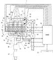
図1は、本実施形態に係る4サイクルの過給機付き多気筒エンジン1の全体を模式的に示す図である。
車両に搭載されるエンジン本体2には、図面の右から、No.(ナンバー)1気筒3a、No.2気筒3b、No.3気筒3c、No.4気筒3dの4つの気筒3が直線上において、略直列的に形成されており、エンジン1の運転中は、各気筒とも独立して、No.1気筒3a、No.3気筒3c、No.4気筒3d、No.2気筒3b、No.1気筒3aの順で、順次着火、燃焼が繰り返される。
各気筒3,・・・,3の気筒は、それぞれ同様な構成をしており、特にNo.4気筒3dについて説明すると、各気筒3には図示しない往復動可能なピストンが設置されて、このピストンの頂部と気筒内壁面とにより燃焼室4が形成されている。燃焼室4において、ピストン頂部と対面する内壁面には、2つの吸気弁開口と、2つの排気弁開口とが形成されており、これら2つの吸気弁開口を開閉させる2つの吸気弁5と、2つの排気弁開口を開閉させる2つの排気弁6とが設けられている。尚、以下、エンジン1において、燃焼室4の中心に対してピストン頂部側を指向する方向を、エンジン1の下側と称し、その反対側で吸気弁5や排気弁6側を指向する方向を、エンジンの上側と称すこととする。
これら2つの吸気弁5は、全気筒共通の吸気カム軸7aによって開閉駆動されるとともに、吸気バルブタイミング機構7によって、その開弁時期と閉弁時期との間の開弁期間の位相を、全体的に進角や遅角することで調整可能となっている。一方、2つの排気弁6は、全気筒共通の排気カム軸8aによって開閉駆動されるとともに、排気バルブタイミング機構8によって、その開弁時期(特許請求の範囲の「開弁開始時期」に相当し、開弁動作を開始した時期。)と閉弁時期(つまり、閉弁動作開始後、全閉が完了した時期)との間の開弁期間の位相を、全体的に進角や遅角することで調整可能となっている。尚、本発明においては、吸気バルブタイミング機構7及び排気バルブタイミング機構8に関して、このように開弁期間の位相を調整するタイプに限らず、開弁期間の長さを変更したり、開弁期間中の吸気弁5あるいは排気弁6の開弁リフト量を変更可能なタイプのものであっても構わない。
FIG. 1 is a diagram schematically showing the entire
From the right side of the drawing, the
The
These two
また、燃焼室4において、ピストン頂部の対面する面の略中央には、燃焼室4内に吸入された混合気を着火する点火プラグ9が設置されている。
全気筒のピストンの往復動の運動により、各ピストンと連結されたクランク軸10は回転されて、この時の回転トルクは、クランク軸10と連結したドライブプレート11を介して、図示しない動力伝達機構から車輪に伝達され、これにより車両は走行可能となる。
Further, in the combustion chamber 4, an
The
全燃焼室4には吸気が供給されており、そのために、大気からエアフィルタ(図示せず)を介して吸入された吸気の吸気量を測定するエアフローセンサ12と、ターボ式の過給機13のコンプレッサ14と、過給機13により過給された吸気を空気により冷却するインタークーラー15とから成る共通吸気通路16が設けられている。
共通吸気通路16の下流側は、2つに分岐して第1分岐吸気通路17,第2分岐吸気通路18が形成されており、第1分岐吸気通路17には、上流側から、電動式で開度を調整可能な第1スロットル弁19と、第1サージタンク20とが設けられており、更に第1サージタンク20から分岐して、No.2気筒3bに吸気を供給するNo.2独立吸気通路21と、No.3気筒3cに吸気を供給するNo.3独立吸気通路22とが設けられている。
Intake air is supplied to all the combustion chambers 4, and for this purpose, an
The downstream side of the
同様にして、第2分岐吸気通路18には、上流側から、電動式で開度を調整可能な第2スロットル弁25と、第2サージタンク26とが設けられており、更に第2サージタンク26から分岐して、No.1気筒3aに吸気を供給するNo.1独立吸気通路27と、No.4気筒3dに吸気を供給するNo.4独立吸気通路28とが設けられている。
このような構成により、着火及び燃焼が連続する気筒同士は、それぞれ第1分岐吸気通路17か第2分岐吸気通路18の内、一方の分岐吸気通路により吸気供給されており、換言すれば、着火及び燃焼が連続しない気筒同士(例えば、No.1気筒3aとNo.4気筒3cの組(群)と、No.2気筒3bとンバー3気筒3cの組(群))は、第1分岐吸気通路17か第2分岐吸気通路18の内、同じ分岐吸気通路から吸気供給されるよう構成される。
以上の4つの独立吸気通路21,22,27,28には、それぞれ燃料噴射弁29(図では、No.4独立吸気通路28に設けられた燃料噴射弁29のみに参照番号を付す。)が設けられている。
Similarly, the second branch intake passage 18 is provided with a
With such a configuration, the cylinders that are continuously ignited and combusted are each supplied with intake air from one of the first
Each of the above four
(排気系の構造について)
次に排気系について説明すると、No.2気筒3bに接続された独立排気通路30(特許請求の範囲に記載の「過給排気通路」及び「分離排気通路」に相当)と、No.3気筒3cに接続された独立排気通路31(特許請求の範囲に記載の「過給排気通路」及び「分離排気通路」に相当)とは、それぞれ過給機13の排気タービン32に排気ガスを供給している。
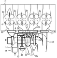
図2にて概略的に示すように、この過給機13は、所謂、ツインスクロールターボ式過給機と称されるもので、2つの独立排気通路30,31から導入される排気ガスに対して、区画された2つの部屋33、34が形成されており、それぞれの部屋33,34に跨るように1つのタービン32が設置されている。このように構成することで、No.2気筒3b、No.3気筒3cから順番に排出される排気ガス流は、各部屋33,34で個別にタービン32と接触するため、各気筒3b,3cの排気ガス流のエネルギーを、気筒3b,3c毎で効率的に回転エネルギーに変換させることが可能となる。これにより、タービン32とシャフトによって接続された吸気側のコンプレッサ14による過給効果を高めることを可能にしている。
特に、このような効果は、エンジン回転数が低く排気ガス量が少ないために、排気ガス流の運動エネルギーが全体的に低くなる状態において、顕著となる。
(Exhaust system structure)
Next, the exhaust system will be described. Independent exhaust passage 30 (corresponding to “supercharged exhaust passage” and “separated exhaust passage” recited in the claims) connected to the two cylinders 3b; The independent exhaust passage 31 (corresponding to the “supercharged exhaust passage” and “separated exhaust passage” described in the claims) connected to the three
As schematically shown in FIG. 2, the
In particular, such an effect becomes remarkable in a state where the kinetic energy of the exhaust gas flow is lowered overall because the engine speed is low and the amount of exhaust gas is small.
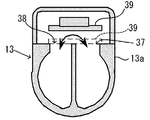
また、本実施形態の過給機13は、タービン32の直ぐ上流側の独立排気通路30と独立排気通路31との間を連通する連通路35が形成されており、連通路35には連通弁36が形成されている。
この連通弁36の構成について、図2のA−A断面を示す図3を参照して説明すると、各独立排気通路30,31の上方の内壁面には、開口37,38が形成されており、開口37,38の上方側には、連通路35となる室が形成されている。各開口37,38に対しては、これらの弁を覆う弁体39が設けられており、この弁体39は、各独立排気通路30,31を形成する壁面の上部に対して、弁体39のエンジン本体2とは反対側の端部が軸支されており、これにより弁体39は、軸支部分を中心として上下方向に回動可能となる。この弁体39を回動動作させるために、弁体39には、エンジン本体2とは反対側且つ斜め上方側に位置するダイヤフラム40と機械的に接続されており、このダイヤフラム40の動作に連動して弁体39が開閉されることになる。
過給機13のタービン32の下流には、第1分岐排気通路41が設置されており、これによりタービン32に供給された排気ガスは第1分岐排気通路41に排出される。
Further, the
The configuration of the
A first
また、No.1気筒3aに接続された独立排気通路42(特許請求の範囲に記載の「非過給排気通路」に相当)と、No.4気筒3dと接続された独立排気通路43(特許請求の範囲に記載の「非過給排気通路」に相当)とは、それぞれ下流側において、過給機13を介さずに第2分岐排気通路44と接続される。尚、No.1気筒3aの独立排気通路42、No.4気筒3dの独立排気通路43及び第2分岐排気通路44は、熱容量が低い板金製の排気管により形成されている。
No. An independent exhaust passage 42 (corresponding to the “non-supercharged exhaust passage” recited in the claims) connected to the one
こうした各独立排気通路の構成により、着火及び燃焼が連続する気筒同士は、それぞれ第1分岐排気通路41か第2分岐排気通路44の内、一方の分岐排気通路に接続されている。換言すれば、着火及び燃焼が連続しない気筒同士(例えば、No.1気筒3aとNo.4気筒3cの組(群)と、No.2気筒3bとNo.3気筒3cの組(群))は、第1分岐排気通路41か第2分岐排気通路44の内、同じ分岐排気通路に接続されるよう構成されることになる。
このような構成により、一般に分岐排気通路を形成すると、各気筒と分岐排気通路の上流端との間に介在する独立排気通路の排気通路長が短くなるが、この場合における各気筒の掃気性を向上できる。つまり、着火及び燃焼が連続する気筒同士を接続すると、これらの気筒同士では排気行程も連続することから、一方の気筒の排気行程が開始された後に他方気筒の排気行程が開始されることとなる。その際、独立排気通路の排気通路長が短いと、このように近接して前後する各気筒に対して、各独立排気通路を介して他方側の気筒の排気ガス圧力が作用することになり、各気筒の排気ガスの掃気性を悪化させてしまう。
そこで、排気行程が連続しない、つまり着火及び燃焼が連続しない気筒同士を、同じ分岐排気通路に接続させることで、こうした掃気性の悪化を防止している。
Due to the configuration of each independent exhaust passage, the cylinders that are continuously ignited and combusted are connected to one of the first
In general, when the branch exhaust passage is formed by such a configuration, the exhaust passage length of the independent exhaust passage interposed between each cylinder and the upstream end of the branch exhaust passage is shortened. In this case, the scavenging performance of each cylinder is reduced. Can be improved. In other words, when cylinders that are continuously ignited and combusted are connected, the exhaust strokes of these cylinders also continue, so that after the exhaust stroke of one cylinder is started, the exhaust stroke of the other cylinder is started. . At that time, if the length of the exhaust passage of the independent exhaust passage is short, the exhaust gas pressure of the other cylinder acts on each of the cylinders that come back and forth in this manner through each independent exhaust passage, The scavenging performance of the exhaust gas in each cylinder is deteriorated.
Therefore, the deterioration of the scavenging property is prevented by connecting the cylinders in which the exhaust stroke does not continue, that is, in which the ignition and combustion do not continue, to the same branch exhaust passage.
以上のような構成に対し、本実施形態では、更に、タービン32と接続されるNo.2気筒3b及びNo.3気筒3cにおいて、こられの気筒の各排気弁6に、タービン32を近接配置している。つまり、図2に示すように、エンジン本体2において、位置的に隣接するとともに着火順序が連続しないNo.2気筒3b及びNo.3気筒3cが位置する部分の独立排気通路30,31側に、過給機13のタービン32および連通路35をケーシングするハウジング13aを直結させている。
このような構成により、No.2気筒3b及びNo.3気筒3cから排出される排気ガスを、そのガス流のエネルギーが大きく低下する前に、タービン32に接触させることができる。
In contrast to the configuration as described above, in the present embodiment, No. 2-cylinder 3b and No. 2 In the three
With this configuration, No. 2-cylinder 3b and No. 2 The exhaust gas discharged from the three
これについて具体的に説明すると、先ず、一つの気筒3の独立排気通路において、一方の排気弁6からタービン32までの最短の排気通路長と、他方の排気弁6からタービン32までの最短の排気通路長との平均長さを、1つの気筒3における排気弁6からタービン32までの気筒平均排気通路長と定義する。
このような定義に基づき、着火及び燃焼が連続せずタービン32に接続されるNo.2気筒3bとNo.3気筒3cとに関し、No.2気筒3bに接続される独立排気通路30の気筒平均排気通路長と、No.3気筒3cに接続される独立排気通路31の気筒平均排気通路長とを求め、この平均を2−3気筒平均排気通路長(特許請求の範囲に記載の「全ての上記一方側気筒における上記排気弁から上記ターボ過給機までの排気ガスが流れる経路の長さの平均」に相当)とする。同様にして、着火及び燃焼が連続せずタービン32とは接続されないNo.1気筒3aとNo.4気筒3dとに関しても、各気筒3a,3dの気筒平均排気通路長をそれぞれ求め、これらの平均を、1−4気筒平均排気通路長(特許請求の範囲に記載の「全ての該他方側気筒における上記排気弁から該合流部までの排気ガスが流れる経路の長さの平均」に相当)する。
この場合、2−3気筒平均排気通路長は、1−4気筒平均排気通路長よりも短くなるよう設定されている。
これにより、No.2気筒3b及びNo.3気筒3cにおける過給効果を確実に高めることができる。また、No.1気筒3a及びNo.4気筒3dにおいては、平均的に排気弁からタービン32までの長さが長くなるため、着火及び燃焼が連続しない気筒同士を接続する構成も相まって、各気筒間の排気干渉を抑制して、掃気効果を向上している。
また、本実施形態において、No.2気筒3bとNo.3気筒3cとにおける各気筒平均排気通長を明確に規定すると、これらの気筒における各気筒平均排気通路長、は70mmとなる。尚、これらの気筒の気筒平均排気通長は、100mm以下がよいとされるが、70mm以下が好ましく、下限は、可能な限り短い方が好ましいが、レイアウト上30mm程となる。
Specifically, first, in the independent exhaust passage of one
Based on such a definition, the ignition and combustion are not continued and the No. 2-cylinder 3b and No. Regarding the three
In this case, the 2-3 cylinder average exhaust passage length is set to be shorter than the 1-4 cylinder average exhaust passage length.
As a result, no. 2-cylinder 3b and No. 2 The supercharging effect in the three
In this embodiment, No. 2-cylinder 3b and No. If the average exhaust passage length of each cylinder in the three
また、タービン32に接続される独立排気通路30と独立排気通路31とは、それぞれ排気弁6,6からタービン32までにおける独立排気通路30,31の容積が、その独立排気通路30,31に接続される気筒3b,3cのシリンダ容積(ピストンが下死点にある状態における気筒内容積)と同じか若しくはこれよりも小さくなるよう形成してもよい。この場合、好ましくは、各気筒3において、シリンダ容積に対する、排気弁6,6からタービン32までにおける独立排気通路30,31の容積の割合を、1/2以下にすればよい。
これにより、タービン32と排気弁6との距離を短くして、排気ガス流の運動エネルギーが大幅に減少される前にタービン32に接触させることで、排気ガス流の運動エネルギーを、高効率でタービン32の回転エネルギーに変換できる。
Further, the
Thereby, the distance between the
一方、本実施形態では、No.4気筒3dの独立排気通路43はNo.1気筒3aの独立排気通路42を指向して湾曲し、過給機13の下方側を通って、この第2分岐排気通路44に接続しているが、この集合構造は、本実施形態の構造に限定されない。
On the other hand, in this embodiment, no. The
第1分岐排気通路41と第2分岐排気通路44とは、その下流側において合流することで、共通排気通路45に連通されており、共通排気通路45には、排気ガス中のO2(酸素)濃度が略0.5%を挟んで、短時間に反転され続けることで、排気ガス中の一酸化炭素、炭化水素、窒素酸化物とを浄化可能とする、貴金属を担持した三元触媒46(特許請求の範囲の「触媒」に相当)が設置されている。
また三元触媒46の下流の共通排気通路45には、排気ガス中のO2濃度が継続的に略2%以上の状態では、排気ガス中に含有される窒素酸化物を積極的に吸収して窒素酸化物の大気放出量を低減するとともに、その後、一時的に(例えば3数秒間以内)排気ガス中のO2濃度を1%以下(好ましくは、0.5%以下)にすることで、吸収した窒素酸化物を積極的に放出するアルカリ土類金属などから成るNOx吸収材と、放出される窒素酸化物を浄化する貴金属とを担持するNOx吸収触媒47(特許請求の範囲の「触媒」に相当)が設置されている。尚、NOx吸収触媒47に代えて、NOx吸収材を含有する担体と、放出された窒素酸化物とを浄化する担体とがそれぞれ分離されたユニットであっても構わない。
NOx吸収触媒47を通過した排気ガスは、その後大気放出される。
The first
Further, in the
The exhaust gas that has passed through the
タービン32を介在しない第2分岐通路44を流れる排気ガスの一部は、吸気循環通路48を通ってコンプレッサ14上流の共通吸気通路16に供給されており、この吸気循環通路48を流通する一部の排気ガスの量(吸気循環量)を調整するための吸気循環バルブ48aが設けられている。
A part of the exhaust gas flowing through the
(エンジン制御について)
以上のようなエンジン1を駆動するために、エンジン1には各種のセンサと各種のアクチュエータとが設置されており、次にこれについて詳細に説明する。
図1に示すように、エンジン1には、上述の吸入空気量センサ12の他、第1サージタンク内の過給圧を検出する第1過給圧センサ49a、第2サージタンク内の過給圧を検出する第2過給圧センサ49b、インタークーラー直ぐ下流の吸気温度を検出する吸気温度センサ(図示せず)、エンジン本体2の冷却水温度を介してエンジン温度を検出可能なエンジン温度センサ(図示せず)、吸気バルブタイミング機構7に内蔵された吸気カム軸7aの回転位相を検出する吸気カム角度センサ(図示せず)、排気バルブタイミング機構8に内蔵された排気カム軸8aの回転位相を検出する排気カム角度センサ(図示せず)、ドライブプレート11の回転状態を検出することで、クランク軸10の回転数や回転位相を検出可能とするピックアップセンサ50、第1分岐排気通路41を流通する排気ガス中のO2濃度を線形的に検出可能な第1リニアO2センサ51a、第2分岐排気通路44を流通する排気ガス中のO2濃度を線形的に検出可能な第2リニアO2センサ51b、車室内のアクセルペダルの開度を検出するアクセル開度センサ52が設けられている。これらの検出信号は、車載された制御部53に出力されている。
また、制御部53は、これらの検出信号に基づいて、各種各気筒3に供給する燃料の燃料噴射量や燃料噴射時期、各気筒の点火時期、吸気弁5や排気弁6による各開弁期間を演算して、燃料噴射弁29、点火プラグ9、吸気バルブタイミング機構7、及び排気バルブタイミング機構8を制御するとともに、第1スロットル弁19及び第2スロットル弁25の開度、連通弁36の開度、及び吸気循環バルブ48aの開度を演算し、これらのアクチュエータも制御している。
(About engine control)
In order to drive the
As shown in FIG. 1, the
Further, based on these detection signals, the
次に、本実施形態に係るエンジン制御について詳細に説明する。
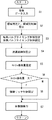
図4は、制御部53における制御フローチャート図であり、この図に示すように、クランク軸10の所定のクランク角度毎にスタートされた後、ステップS1に進み、上述の各種センサから検出信号を入力して次にステップS2に進む。尚、ステップS1では、ピックアップセンサ50からの検出信号に基づいて、エンジン回転数(回転速度)を算出し、ピックアップセンサ50及び吸気カム軸センサからの検出信号に基づいて、所定の気筒の1サイクルにおける行程を判別している。また、各気筒3内に供給される吸気量は、エアフローセンサ12で検出された吸気量を、各過給圧センサ49a、49bでの検出値と、吸気温度センサでの検出値とに基づいて補正し、実際に各気筒3内に供給される吸気量を精度よく検出している。
Next, engine control according to the present embodiment will be described in detail.
FIG. 4 is a control flowchart in the
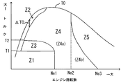
ステップS2では、エンジン回転数と、アクセル開度により求まるトルクとに基づいて、図5に示すような多数の運転領域を区画する制御マップにおける現状の運転領域を判定し、判定された領域に基づいて空燃比制御を行なうために、燃料噴射量及びスロットル弁開度を設定している。また、ステップS2では、同時に、この制御マップにより規定されるエンジン制御を行なうために、吸気循環バルブ制御の制御量についても設定している。 In step S2, the current operating region in a control map that divides a number of operating regions as shown in FIG. 5 is determined based on the engine speed and the torque obtained from the accelerator opening, and based on the determined region. In order to perform air-fuel ratio control, the fuel injection amount and the throttle valve opening are set. In step S2, at the same time, in order to perform engine control defined by this control map, the control amount of intake air circulation valve control is also set.
図5に示す制御マップを詳細に説明すると、エンジン回転数が第1回転数Ne1以下で、トルクがT1以下の運転領域Z1(特許請求の範囲に記載の「低回転低負荷状態」に相当する領域)の時には、タービン32に接続されているNo.2気筒3bとNo.3気筒3cとは、空燃比(吸気量/燃料供給量)が理論空燃比(14.7)近傍となるよう制御される(理論空燃比制御)とともに、タービン32に接続されていないNo.1気筒3aとNo.4気筒3dとは、燃料噴射弁29による燃料噴射が実質的に行なわれず、所謂、燃料カットされるよう設定されている。これにより、エンジン1全体から見れば、所謂、減筒運転が実行されることになる。
尚、この時、No.2気筒3bとNo.3気筒3cとで実行されるような空燃比が理論空燃比近傍となるような制御は、所謂、λ=1制御とも呼ばれるものである。具体的には、第1リニアO2センサ51aから検出信号に基づいて、各気筒3の空燃比は、理論空燃比(つまり、λ=1)を挟んで、リッチ(吸気量に対する燃料供給量の割合が多く、燃焼後の排気ガス中のO2濃度が略0.5%未満の状態)とリーン(吸気量に対する燃料供給量の割合が少なく、燃焼後の排気ガス中のO2濃度が略0.5%以上の状態)とを短期間で反転しながらこれを継続するようF/B制御されている。このようなF/B制御を実行するために、図示しないが、マップは、第1スロットル弁19の開度を所定開度TV11とするよう設定しており、これに対して空燃比の制御に際して応答性の良い燃料噴射量が、F/B制御されることになる。
The control map shown in FIG. 5 will be described in detail. The engine speed is equal to or lower than the first speed Ne1 and the torque is equal to or lower than T1. No.) connected to the
At this time, no. 2-cylinder 3b and No. Control in which the air-fuel ratio that is executed by the three
また、この領域Z1では、No.1気筒3aとNo.4気筒3dに接続される第2スロットル弁25の開度は、略全開相当となるよう設定されるとともに、これらの気筒と第2分岐通路44を介して接続された吸気循環通路48に設置された吸気循環バルブ48aは略全開に制御されるよう設定されており、これにより減筒制御におけるポンピング損失が大幅に低減されることになる。尚、後述する領域Z1以外の領域では、吸気循環バルブ48aは略全閉に設定される。
このように領域Z1では、タービン32に接続されたNo.2気筒3b、No.3気筒3cでは、理論空燃比で運転されるため、タービン32を予回転(つまり、予過給)させておくことができ、この領域Z1での運転中に加速運転がされた場合における過給機13による過給遅れを抑制できる。一方、低負荷低回転にも拘わらず、理論空燃比による運転が行なわれるため、この技術では燃費向上が図れないが、タービン32に接続されないNo.1気筒3a、No.4気筒3dでは、ポンピング損失を低減しながら燃料カットされるため、これにより全体的に燃費向上を図ることが可能となる。
In this region Z1, No. 1
As described above, in the region Z1, No. connected to the
エンジン回転数が第1回転数Ne1以下で、トルクがT1からT2との間の低回転部分負荷領域Z2(但し、後述する領域Z3は除く)では、タービン32に接続されているNo.2気筒3bとNo.3気筒3cとは、空燃比(空気/燃料供給量)が理論空燃比よりもリーンな空燃比(例えば、A/F=20〜25)近傍となるよう制御設定される(リーン空燃比制御)。このようなリーン空燃比制御を実行するために、マップには、第1スロットル弁19の開度を、開度TV11よりも大きい開度TV12となるよう設定されており、これに対して燃料噴射量は、空燃比がリーンとなるように予め設定された量で噴射されるよう設定されている(フィードフォワード(F/F)制御)。尚、このリーン空燃比制御についても、第1リニアO2センサ51aの検出信号に基づいて、目標空燃比を理論空燃比よりもリーンな空燃比に設定してF/B制御してもよい。
一方、この低回転部分負荷領域Z2では、タービン32に接続されていないNo.1気筒3aとNo.4気筒3dとについても、上述のようなリーン空燃比制御を実行するよう設定される。尚、第2スロットル弁25の開度TV2は、略開度TV12と同等となる。
また、No.1気筒3aとNo.4気筒3dにおけるリーン空燃比制御をF/B制御で実行する場合には、排気ガス中のO2濃度は、第1リニアO2センサ51bによって検出されることになる。
低回転部分負荷領域Z2においては、このように全気筒において、リーン空燃比制御が実行されることで、燃費を向上できる。
In the low rotation partial load region Z2 (excluding the region Z3 described later) where the engine rotation speed is equal to or lower than the first rotation speed Ne1 and the torque is between T1 and T2, No. 2-cylinder 3b and No. The three-
On the other hand, in this low rotation partial load region Z2, No. 1
No. 1
In the low rotation partial load region Z2, the fuel efficiency can be improved by executing the lean air-fuel ratio control in all the cylinders.
エンジン回転数が第1回転数Ne1付近以下で、トルクが、全開トルクToと全開トルクToから微小なトルクΔToを減算した所定トルクとの間にある低回転全負荷領域Z3では、全気筒に亘って、上述のようなF/B制御による理論空燃比制御を実行するよう設定される。この時、タービン32に接続されていないNo.1気筒3aとNo.4気筒3dとについては、排気ガス中のO2濃度検出のために、第2リニアO2センサ51bが用いられる。
このように低回転全負荷領域Z3では、全気筒において理論空燃比制御が実行されるため、十分なトルクが得られ、例えば加速初期における出力不足を防止できる。また、この時には、アクセル開度に応じて第1及び第2スロットル弁19,25の開度も大きく開成されるため吸気量が多い状態となり、合わせて理論空燃比運転されることによる排気ガス流のエネルギーも高いため、過給機13の過給効率が高い状態にある。よって、更に、高い出力の供給が可能となる。
In the low rotation full load region Z3 where the engine speed is less than or equal to the first rotation speed Ne1 and the torque is between the fully open torque To and a predetermined torque obtained by subtracting a small torque ΔTo from the fully open torque To, Thus, the theoretical air-fuel ratio control by the F / B control as described above is set to be executed. At this time, no. 1
In this way, in the low rotation full load region Z3, since the theoretical air-fuel ratio control is executed in all the cylinders, sufficient torque can be obtained, and for example, output shortage at the initial stage of acceleration can be prevented. Further, at this time, the opening degree of the first and
エンジン回転数が第2回転数Ne2以下で、上述の領域Z1、Z2、及びZ3の領域を除いた領域Z4aと、エンジン回転数が第2回転数Ne2と第3回転数Ne3との間で、低トルク側の領域Z4bとを合わせた部分負荷領域Z4では、タービン32に接続されているNo.2気筒3bとNo.3気筒3cとは、上述のようにリーン空燃比制御を実行するとともに、タービン32に接続されていないNo.1気筒3aとNo.4気筒3dとは、上述のような理論空燃比制御を実行するよう設定されている。
尚、第1及び第2スロットル弁19,25の各開度TV1,TV2とも、上述の開度TV11より大きい開度でエンジン回転数及びトルクが増大するにつれて、開度が大きくなるよう設定されるが、第1スロットル弁19の開度TV1と第2スロットル弁25の開度TV2とを比較すると、開度TV2の方が小さくなるよう設定されている。
このような制御により、一部の気筒についてはリーン空燃比制御が実行されることで、燃費を向上することができるとともに、この時、残りの気筒では、理論空燃比制御により排気ガス流のエネルギーを増大させて過給機13による過給効果を向上することで、高出力化を図っており、つまりは、確実に燃費を向上できる。また、これにより全体的に高出力化が可能となるためエンジン本体2、延いてはエンジン1を全体的に小型化することも可能となる。
The engine speed is equal to or lower than the second speed Ne2, and the area Z4a excluding the above-described areas Z1, Z2, and Z3, and the engine speed is between the second speed Ne2 and the third speed Ne3, In the partial load region Z4 combined with the region Z4b on the low torque side, the No. 2-cylinder 3b and No. The three-
Note that the opening degrees TV1 and TV2 of the first and
With such control, lean air-fuel ratio control is executed for some cylinders, so that fuel efficiency can be improved. At this time, the energy of the exhaust gas flow is determined by theoretical air-fuel ratio control for the remaining cylinders. Is increased to improve the supercharging effect by the
エンジン回転数が少なくとも第3回転数Ne3以上で、上記領域Z4以外の高回転領域Z5では、タービン32に接続されているNo.2気筒3bとNo.3気筒3cとは、上述のような理論空燃比制御を実行するとともに、タービン32に接続されていないNo.1気筒3aとNo.4気筒3dとは、上述のようなリーン空燃比制御を実行するよう設定されている。 尚、第1及び第2スロットル弁19,25の各開度TV1,TV2とも、基本的に領域Z4における各開度TV1,TV2よりそれぞれ大きい開度で、エンジン回転数及びトルクが増大するにつれて大きくなるよう設定されるが、第1スロットル弁19の開度TV1と第2スロットル弁25の開度TV2とを比較すると、TV1の方が小さくなるよう設定されている。
このような制御により、一般的に、高回転運転状態では、タービン32に接続されている気筒3をリーン運転すると、出力向上のために過給効率増大が要求される運転域であるにもかかわらず、リーン運転により排気ガス流のエネルギーが増大されずに過給効率を高めることができない状態となってしまい、出力不足が発生する。そこで、本実施形態では、タービン32に接続されているNo.2気筒3bとNo.3気筒3cとに対しては、理論空燃比制御を実行して、過給機13による過給効率を増大させて出力増大を図るとともに、一方で、タービン32に接続されていないNo.1気筒3aとNo.4気筒3dとは、リーン空燃比制御にして、出力及び燃費を向上させている。
In the high speed region Z5 other than the region Z4, the engine speed is at least the third speed Ne3 or higher. 2-cylinder 3b and No. The three-
By such control, in general, in a high-speed operation state, if the
また、高速運転である領域Z5では、NOx吸収触媒47が熱劣化し易いが、No.1気筒3a及びNo.4気筒3dの空燃比を理論空燃比近傍よりもリーンにすることで、No.1気筒3a及びNo.4気筒3dから比較的低温の排気ガスが排出されて、NOx吸収触媒47の昇温による熱劣化を防止できる。
一方、理論空燃比制御されるNo.2気筒3b及びNo.3気筒3cから排出される高温の排気ガスは、熱容量が大きいタービン32やケース13a等と接触して冷却されNOx吸収触媒47に導入される。従って、上述のように、No.2気筒3bとNo.3気筒3cとに対する理論空燃比制御により過給効率の増大を図りつつ、NOx吸収触媒47の昇温による熱劣化を防止できる。
尚、この領域Z5においては、タービン32に接続されているNo.2気筒3bとNo.3気筒3cとは、理論空燃比よりもリッチな空燃比で運転されるよう設定してもよく、これにより更なる高出力化が可能となる。
Further, in the region Z5 which is high speed operation, the
On the other hand, no. 2-cylinder 3b and No. 2 The high-temperature exhaust gas discharged from the three
In this region Z5, the No. connected to the
次に、ステップS3に進み、全気筒における吸気弁5と排気弁6とのバルブタイミング制御を実行するため、バルブタイミング制御の各種制御量が設定される。
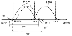
先ずは、排気バルブタイミング機構8による排気バルブタイミング制御について説明すると、図6に示すように、排気弁6の開弁期間EOPは、開弁時期EOT(特許請求の範囲の「開弁開始時期」に相当し、開弁動作を開始した時期)と閉弁時期ECT(閉弁動作開始後、全閉が完了した時期)との間の期間として規定されている。このように規定された開弁期間EOPは、エンジン回転数が低回転側で且つトルクが大きい程、カムプロフィールを維持したまま遅角側にシフト設定される(EOP1参照)。
具体的には、図7の制御マップで示されるように、領域Z2の全域と、領域Z3、Z4の低回転且つ高トルク側の領域と、領域Z1の低回転且つ高トルク側の領域とを合わせた領域C1において、開弁期間EOPは、それ以外の領域CEにおける開弁期間EOPよりも遅角側に設定される。また、特に、領域Z2の全域と、領域Z4のより低回転且つ高トルク側の領域とを合わせた領域C2においては、開弁期間EOP1(開弁時期EOT1と閉弁時期ECT1との間の期間)は、領域CEにおける開弁期間EOPに対して最大に遅角されている。具体的には、領域CEにおける開弁期間EOPに対して、領域C2における開弁期間EOP1は、クランク角度にして略10°から略50°、燃焼安定性なども考慮して好ましくは略30°から略40°程遅角設定される。
Next, in step S3, various control amounts for valve timing control are set in order to execute valve timing control of the
First, the exhaust valve timing control by the exhaust
Specifically, as shown in the control map of FIG. 7, the entire region Z2, the low rotation and high torque side regions of the regions Z3 and Z4, and the low rotation and high torque side region of the region Z1 In the combined region C1, the valve opening period EOP is set to be retarded from the valve opening period EOP in the other regions CE. In particular, in the region C2 that combines the entire region of the region Z2 and the region on the lower rotation and high torque side of the region Z4, the valve opening period EOP1 (the period between the valve opening timing EOT1 and the valve closing timing ECT1). ) Is retarded to the maximum with respect to the valve opening period EOP in the region CE. Specifically, with respect to the valve opening period EOP in the region CE, the valve opening period EOP1 in the region C2 is approximately 10 ° to approximately 50 ° in terms of a crank angle, preferably approximately 30 ° in consideration of combustion stability and the like. From about 40 °.
これにより、上述のように、排気弁6とタービン32との間の気筒平均排気通路長の経路が短いNo.2気筒3bとNo.3気筒3cとにおいては、低回転運転状態であっても排気弁6の開弁期間EOPを遅角化することで排気ガス流のブローダウン効果を高めることが可能となる。よって、高効率で排気ガス流のエネルギーをタービン32の回転エネルギーに変換させることができ、全気筒において低回転運転時に高い過給効果を得ることが可能となる。
特に、本実施形態では、過給効果の要求が高い低回転側且つ高トルク側において、開弁期間EOPを大幅に遅角することにより、高い過給効果を発現させることが可能となる。また、高回転側の領域CEは、このような排気弁6の開弁期間EOPの遅角化を行わなくても十分過給効果が高いため、過度な過給を防止するため、排気弁6の開弁期間EOPの遅角化が抑制される。また、低回転側且つ低トルク側は、排気弁6の開弁期間EOPの大幅な遅角化を行なうと、燃焼室4内に逆流する排気ガスの割合が増大するため、こうした遅角化は抑制される。
As a result, as described above, the cylinder No. 1 exhaust passage length between the
In particular, in the present embodiment, a high supercharging effect can be exhibited by significantly retarding the valve opening period EOP on the low rotation side and the high torque side where the supercharging effect is required. Further, the region CE on the high rotation side has a sufficiently high supercharging effect without performing the retarding of the valve opening period EOP of the
尚、吸気バルブタイミング機構7による吸気バルブタイミング制御は、本発明に関しては直接的に影響しないため、説明は省略する。
Note that the intake valve timing control by the intake
次に、ステップS4に進み、連通通路35の連通弁36の開閉制御を実行するための制御量を設定する。
連通弁36は、エンジン回転数が第4回転数Ne4(但し、第4回転数Ne4は第2回転数Ne2付近の回転数となる)以下であれば閉成され、第4回転数Ne4より大きければ開成されるよう設定される。
これは、排気弁6とタービン32との間の気筒平均排気通路長の経路が短いNo.2気筒3bとNo.3気筒3cとにおいては、エンジン回転数が第3回転数Ne3以下の時には、各気筒からの適切な量の排気ガス流を的確にタービン32に接触させることができるが、エンジン回転数が第3回転数Ne3より大きい時には、1気筒当たりの排気ガス流が過剰に増大して、排気ガスがタービン32直前で詰まるような状態になり、排気ガス流のエネルギーを効率的にタービン32の回転エネルギーに変換させることができなくなり、これを防止するためである。
このような状態においては、連通弁36を開成することで、No.2気筒3bとNo.3気筒3cとの内、過剰に増大した一方側の気筒の排気ガスを、着火サイクル時期の違いから、この時には大量の排気ガスが流れていない他方側の気筒の独立排気通路へ逃がすことができ、これにより排気ガス流のエネルギーをタービン32の回転エネルギーへ効率的に変換させることが可能となる。
Next, it progresses to step S4 and the control amount for performing opening / closing control of the
The
This is because the cylinder average exhaust passage length between the
In such a state, by opening the
次に、ステップS5に進み、NOx吸収触媒47に吸収されている窒素酸化物吸収量が推定される。この推定方法は、例えば、NOx吸収触媒47の排気上流と下流とに設置された各NOxセンサ(図示せず)や各O2センサ(図示せず)の検出結果に基づいて、公知の手法により検出される。尚、本手法は、こうしたセンサに拠らず所定時間毎に窒素酸化物吸収量が多いと判定するものも含む。
その後、ステップS6に進み、窒素酸化物吸収量が所定量以下で、まだ十分窒素酸化物を吸収可能であると判断した時には、ステップS7に進んで、ステップS2、S3、S4で設定された各気筒の燃料噴射量、第1スロットル弁19及び第2スロットル弁25の開度、吸気循環バルブ48aの開度、吸気弁5の開弁期間IOP、排気弁6の開弁期間EOP、連通弁36の開度に対応して、燃料噴射弁29や各種アクチュエータ等が駆動され、各制御が実行される。尚、この時、燃料噴射時期や、点火プラグ9の点火時期も予め設定された通りに制御実行されることになる。その後、スタートに戻り、次に着火される気筒に対する制御が行なわれる。
Next, proceeding to step S5, the nitrogen oxide absorption amount absorbed by the
Thereafter, the process proceeds to step S6, and when it is determined that the nitrogen oxide absorption amount is equal to or less than the predetermined amount and the nitrogen oxide can be sufficiently absorbed, the process proceeds to step S7, and each of the values set in steps S2, S3, and S4 is set. The fuel injection amount of the cylinder, the opening degree of the
一方、ステップS6において、窒素酸化物吸収量が所定量以上であり、NOx吸収触媒47からNOxを放出するよう強制的に空燃比制御する必要があると判断した時には、ステップS8に進む。
ステップS8では、図5の制御マップに拠らず、強制的に、NOx吸収触媒47に流入する排気ガスのO2濃度が略1%以下となるように空燃比制御されるが、本実施形態においては、このような空燃比制御のために、タービン32に接続されないNo.1気筒3aとNo.4気筒3dとに対して、強制リッチ制御が実行されることになる。但し、この場合、タービン32に接続されたNo.2気筒3b及びNo.3気筒3cは、図5の制御マップに基づいた空燃比制御が実行される。
強制リッチ制御について具体的に説明すると、先ずは、現時点における全気筒による空燃比制御の実行状況から、強制リッチ制御によりNOx吸収触媒47に流入する排気ガスのO2濃度を略1%以下とするには、No.1気筒3a及びNo.4気筒3dの各気筒の燃料噴射量と、吸気量とをどれぐらいに設定すればよいか、つまり、No.1気筒3a及びNo.4気筒3dの各気筒の空燃比をどれくらいに設定するかが演算される。
On the other hand, if it is determined in step S6 that the nitrogen oxide absorption amount is equal to or greater than the predetermined amount and it is necessary to force air-fuel ratio control to release NOx from the
In step S8, the air-fuel ratio is controlled so that the O2 concentration of the exhaust gas flowing into the
The forced rich control will be specifically described. First, based on the current execution state of the air-fuel ratio control by all the cylinders, the O2 concentration of the exhaust gas flowing into the
この結果、例えば、タービン32に接続されたNo.2気筒3b及びNo.3気筒3cがリーン空燃比制御により理論空燃比よりもリーンな空燃比で運転されている時(領域Z3やZ4における運転中)には、タービン32に接続されないNo.1気筒3a及びNo.4気筒3dの各気筒の空燃比は、理論空燃比よりもリッチな空燃比(例えば、A/F=12から14)となるよう設定される。
また、No.2気筒3b及びNo.3気筒3cが理論空燃比制御により理論空燃比近傍で運転されるとともに、No.2気筒3b及びNo.3気筒3cは、リーン空燃比制御によりリーンな空燃比で運転されている時(領域Z5)では、全気筒において理論空燃比制御若しくは空燃比が理論空燃比よりもリッチな空燃比となるようなリッチ空燃比制御が設定される。
As a result, for example, No. connected to the
No. 2-cylinder 3b and No. 2 The three
このような設定により、NOx吸収触媒47の窒素酸化物の放出及び浄化のために、タービン32に接続されたNo.2気筒3bやNo.3気筒3cに対して強制リッチ制御が設定されることがないため、過給機13の過度な過給を抑制することができ、こうした過過給によるトルクショックの低減が可能となる。
また、領域Z4を運転中の場合にNOx吸収触媒からNOx放出を行なう必要が生じた場合には、理論空燃比制御が実行されているNo.1気筒3a及びNo.4気筒3dに対して、強制リッチ制御が実行されることになるため、No.1気筒3a及びNo.4気筒3dの空燃比は、理論空燃比近傍とこれよりリッチ側との間で移行させればよく、空燃比を、理論空燃比近傍を挟んでリッチとリーンとの間で大幅に移行させる場合に比べて空燃比移行制御に伴うトルクショックが低減される。
更に、こうしたNo.1気筒3a及びNo.4気筒3dに対する強制リッチ制御における空燃比の移行制御では、燃料噴射量の増量のみで移行が行なう場合には、応答性よく空燃比を移行させることができる。また、吸気量を減量してよりリッチ度合を高めるために、第2スロットル弁25を、所定開度分だけ閉弁する場合があるが、このような場合においても、上述のように、空燃比の変更度合が小さいために、第2スロットル弁25の開度の変更量も低減でき、これにより空燃比の移行における応答性を高めつつ、更にトルクショックを低減することが可能となる。
With this setting, the NO. 4 connected to the
Further, when it is necessary to perform NOx release from the NOx absorption catalyst while the region Z4 is in operation, the No. in which the theoretical air-fuel ratio control is being executed. 1
Furthermore, such No. 1
次に、ステップS7に進んで、ステップS8の設定結果に基づいて、No.1気筒3a及びNo.4気筒3dの燃料噴射量、第2スロットル弁25の開度が変更されて制御実行される。尚、ステップS2、S3、S4で設定した、No.2気筒3b及びNo.3気筒3cの燃料噴射量、第1スロットル弁19の開度、吸気循環バルブ48aの開度、吸気弁5の開弁期間IOP、排気弁6の開弁期間EOP、連通弁36の開度は、変更されずに、実行される。尚、このような強制リッチ制御は、0.5秒から3秒ぐらい実行することで、NOx吸収触媒47から殆どの窒素酸化物を放出及び浄化さあせることができる。
ステップS7の実行後は、スタートに戻る。
Next, it progresses to step S7 and based on the setting result of step S8, it is No. 1
After execution of step S7, the process returns to the start.
(本実施形態における実験結果)
次に、本実施形態において、各種実験を行なった結果を説明する。
(Experimental result in this embodiment)
Next, the results of various experiments in this embodiment will be described.
先ずは、No.2気筒3b及びNo.3気筒3cの各排気弁6に対して、タービン32を近接配置することによる作用及び効果を、実験結果を参照して説明する。
図8は、1気筒当たりの気筒平均排気通路長(1気筒において、2つの排気弁6におけるそれぞれの排気弁6とタービン32との最短の各排気通路長の平均長さ)と、過給圧及びタービン32上流の排気ガス圧力との関係について示したものである。尚、実験は、シミュレーションにより行い、その際、2リッターの4気筒エンジンのモデルを使用した(以下の実験も同様)。
このグラフにて示すように、気筒平均排気通長が短くなるほど、過給圧(実線)及び排気ガス圧力(破線)は急増しており、気筒平均排気通長は100mm以下、好ましくは70mm以下に設定すれば、高い過給効率が得られている。尚、下限は、可能な限り短い方が好ましいが、レイアウト上30mm程が限度である。
また、この実験結果から、一般的な独立排気通路の断面積を参照すると、シリンダ容積(ピストンが下死点にある状態における気筒内容積)に対する、排気弁6,6からタービン32までの独立排気通路30,31の容積の割合を、1以下、好ましくは1/2以下にすれば、高い過給圧が得られる。
First, no. 2-cylinder 3b and No. 2 The operation and effect of placing the
FIG. 8 shows the cylinder average exhaust passage length per cylinder (the average length of the shortest exhaust passage lengths of the
As shown in this graph, as the cylinder average exhaust gas length becomes shorter, the supercharging pressure (solid line) and the exhaust gas pressure (broken line) increase rapidly, and the cylinder average exhaust gas length becomes 100 mm or less, preferably 70 mm or less. If set, high supercharging efficiency is obtained. The lower limit is preferably as short as possible, but the upper limit is about 30 mm in terms of layout.
In addition, referring to the cross-sectional area of a general independent exhaust passage from this experimental result, the independent exhaust from the
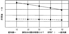
図9は、排気弁6の開弁期間EOPや開弁プロフィールを変化させずに、開弁時期EOTを変更した場合における、過給圧特性について示したグラフである。開弁時期EOTの数値は、排気下死点前のクランク角度を示しており、クランク角度がBTDC52°の時が、高回転時における一般的な排気弁6の開弁時期EOTとなる。また、実線は、気筒平均排気通路長を30mmにした条件での当該特性で、破線は、気筒平均排気通路長を300mmとした条件での当該特性を示している。
このグラフにて示すように、気筒平均排気通路長が短いときには、排気弁6の開弁時期EOTを遅角させることで、過給圧が増大するが、気筒平均排気通路長が長いときには、排気弁6の開弁時期EOTを遅角させても、過給圧の増大は見られない。これにより高い過給効果を得るためには、気筒平均排気通路長を短くして、排気弁6の開弁時期EOTを、BTDC42°から12°(BTDC52°よりも10°から40°遅角側)、好ましくはBTDC22°から12°(BTDC52°よりも30°から40°遅角側)に設定すればよい。
FIG. 9 is a graph showing the supercharging pressure characteristic when the valve opening timing EOT is changed without changing the valve opening period EOP and the valve opening profile of the
As shown in this graph, when the cylinder average exhaust passage length is short, the boost pressure is increased by retarding the valve opening timing EOT of the
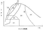
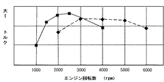
図10は、本実施形態における連通路35の連通弁36を全閉した時におけるエンジン回転数とトルクとの関係(実線)、及び連通弁36を全開した時におけるエンジン回転数とトルクとの関係(破線)について示すグラフである。
この図に示すように、エンジン回転数が3000rpm以下の場合には、連通弁36を全閉にした方がトルクは高い。これは、上述したように、気筒平均排気通路長の経路が短い場合において、低回転時では、1気筒当たりの少ない排気ガス流を確実にタービン32に導くことで、排気ガス流のエネルギーを効率的にタービン32の回転エネルギーに変換させることができるためである。一方、エンジン回転数が3000rpmより大きい場合には、連通弁36を全開にした方がトルクは高い。これは、高回転時では、1気筒当たりの排気ガス流が過剰に増大して、排気ガスがタービン32直前で詰まるような状態になり、排気ガス流のエネルギーを効率的にタービン32の回転エネルギーに変換させることができなくなるためである。よって、高回転時には、過剰に増大した一方側の気筒の排気ガスを、着火サイクル時期の違いから、この時には大量の排気ガスが流れていない他方側の気筒の独立排気通路へ逃がすことにより、排気ガスがタービン32直前で詰まるような状態を解消し、排気ガス流のエネルギーをタービン32の回転エネルギーへ効率的に変換させることが可能となる。
FIG. 10 shows the relationship between the engine speed and torque when the
As shown in this figure, when the engine speed is 3000 rpm or less, the torque is higher when the
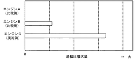
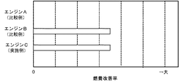
図11、図12は、比較例となるエンジンAに対する、比較例のエンジンBと本実施形態のエンジンCとにおける、部分負荷運転状態でのそれぞれ過給圧増大量と、燃費改善率とを示したグラフである。
尚、エンジンCは、No.2気筒3b及びNo.3気筒3cの各排気弁6に対してタービン32を近接配置したエンジン1において、上述のような領域Z4での部分負荷運転(No.2気筒3b及びNo.3気筒3cはリーン空燃比制御で、No.1気筒3a及びNo.4気筒3dは、理論空燃比制御を実行)を行った時のデータである。これに対して、エンジンAは、過給機を具備しない通常のエンジンにおいて、本実施形態と同様の部分負荷での理論空燃比制御を、4気筒全てに対して実行した時のデータである。また、エンジンBは、4気筒全てからの排気ガス供給を受けて吸気を過給するターボ式過給機を具備したエンジンにおいて、本実施形態と同様の部分負荷でのリーン空燃比制御(A/F=22)を、4気筒全てに対して、実行した時のデータである。
これらの図により、本実施形態であるエンジンCは、高い過給圧により過給効率を高めることで、エンジンBと同等の燃費性能を確保しつつ、高い過給効率を利用して加速時の加速応答性を向上できることが容易に判断される。
11 and 12 show the boost pressure increase amount and the fuel consumption improvement rate in the partial load operation state in the engine B of the comparative example and the engine C of the present embodiment, with respect to the engine A as the comparative example. It is a graph.
Engine C is No. 2-cylinder 3b and No. 2 In the
From these figures, the engine C according to the present embodiment increases the supercharging efficiency by a high supercharging pressure, thereby ensuring the fuel efficiency performance equivalent to that of the engine B and using the high supercharging efficiency during acceleration. It is easily determined that the acceleration response can be improved.
(本実施形態における作用及び効果)
本実施形態においては、過給機13と接続されるNo.2気筒3b及びNo.3気筒3cにおいて、1気筒における排気弁6から過給機13のタービン32までの排気ガスが流れる経路の長さが、100mm以下に短く設定されることになる。これにより、No.2気筒3b及びNo.3気筒3cによる過給機13の過給を増大することができ、よって、全気筒3に対する過給効率を増大させて、エンジン1の出力向上、延いては燃費向上を図ることができる。
また、No.2気筒3b及びNo.3気筒3cは、互いに着火順序が連続しないため、各気筒3の排気干渉を抑制でき、これにより、過給を増大させつつ掃気性も向上できる。更に、No.2気筒3b及びNo.3気筒3cは、略直列的に隣接配置されているため、以上のような過給効率と掃気性との向上が図れるエンジン1を、簡素化された構成で実現できる。
(Operations and effects in this embodiment)
In the present embodiment, No. connected to the
No. 2-cylinder 3b and No. 2 Since the firing order of the three
また、上述のように過給効率を高めたエンジンにおいて、以下のような空燃比制御を実行することで、更なるエンジン1の高出力化及び燃費向上が図れる。
つまり、ターボ式の過給機13のタービン32と接続されたNo.2気筒3b及びNo.3気筒3cに対して、リーン空燃比制御を実行することで、エンジン1の高出力化を図りつつ、燃費を向上させることができる。
また、こうしたNo.2気筒3b及びNo.3気筒3cにおけるリーン空燃比制御により、多量に排出される窒素酸化物を、共通排気通路45に配したNOx吸収触媒47に吸収させることで、空燃比がリーンな状態における窒素酸化物の大気放出を低減できる。また、こうした一部気筒によるリーン空燃比制御の後、タービン32に接続されていないNo.1気筒3a及びNo.4気筒3dに対して一時的に強制リッチ制御が実行されることで、NOx吸収触媒47に吸収された窒素酸化物を放出、浄化させており、これにより、窒素酸化物の大気放出を確実に低減している。
Further, in the engine with the increased supercharging efficiency as described above, by executing the following air-fuel ratio control, it is possible to further increase the output of the
That is, No. connected to the
In addition, such No. 2-cylinder 3b and No. 2 By the lean air-fuel ratio control in the three
特に、本実施形態においては、こうしたNOx吸収触媒47に対する窒素酸化物の放出、浄化のために、上述のようにタービン32に接続されていないNo.1気筒3a及びNo.4気筒3dに対して強制リッチ制御を実行しているが、この時、タービン32と接続されたNo.2気筒3b及びNo.3気筒3cに対しては、リーン空燃比制御を継続させている。従って、タービン32と接続されたNo.2気筒3b及びNo.3気筒3cが強制リッチ制御されることによって発生する過給機13の過過給を防止でき、トルクショックの低減が可能となる。
In particular, in the present embodiment, in order to release and purify the nitrogen oxides with respect to the
また、一般的に、ターボ式過給機13には、コンプレッサ14の下流の過給圧に基づいて、該過給圧が信頼性上問題となるような過給圧より大きくなると、タービン32に流入する排気ガスをタービン32の下流にバイパスするウエスト・ゲート・バルブ機構が設けられている。このようなウエスト・ゲート・バルブ機構により、過給機13の過過給を防止することが考えられるが、タービン32に接続された気筒3b、3cに対して強制リッチ制御を実行すると、排気ガス流のエネルギーは膨大となり、通常のウエスト・ゲート・バルブ機構では、対応できない。
これに対して、本実施形態により、確実に過過給を防止してトルクショック低減が図れる。
In general, the
On the other hand, according to the present embodiment, it is possible to reliably prevent supercharging and reduce torque shock.
(他の実施形態)
尚、本実施形態においては、燃料噴射弁29を各気筒3に対応する独立吸気通路に設置させた、所謂、ポート噴射により、各気筒3に燃料を供給したが、本発明はこれに限定されず、各気筒3内に直接燃料噴射弁を配置して、吸気行程や圧縮行程で燃料噴射を実行する、所謂、直噴によって燃料供給をおこなってもよい。
また、本実施形態においては、No.2気筒3b及びNo.3気筒3cの独立排気通路30,31を、タービン32まで分離した状態となるよう形成したが、タービン32より上流側で、これらの独立排気通路30,31を連通させた構成であってもよい。
また、本実施形態においては、4気筒エンジンについて適応したが、6気筒エンジンやそれ以上の多気筒エンジンにも適応可能である。
この場合、例えばV型6気筒エンジンでは、着火が連続せず、直列的に隣接する気筒3として、片側バンクに位置する3つの気筒3を、タービンに接続してもよい。
また、本実施形態において、排気バルブタイミング制御は、全気筒に対しておこなったが、タービン32に接続されたNo.2気筒3b及びNo.3気筒3cに対してのみおこなってもよい。
また、本発明はディーゼルエンジンにも適応可能である。
(Other embodiments)
In this embodiment, fuel is supplied to each
In this embodiment, no. 2-cylinder 3b and No. 2 Although the
In the present embodiment, the present invention is applied to a four-cylinder engine, but the present invention can also be applied to a six-cylinder engine or a multi-cylinder engine having more than that.
In this case, for example, in a V-type 6-cylinder engine, ignition does not continue, and three
In this embodiment, the exhaust valve timing control is performed for all cylinders. 2-cylinder 3b and No. 2 You may perform only with respect to 3
The present invention is also applicable to diesel engines.
1:エンジン
3a:No.1気筒(他方側気筒)
3b:No.2気筒(一方側気筒)
3c:No.3気筒(一方側気筒)
3d:No.4気筒(他方側気筒)
4:燃焼室
6:排気弁
8:排気バルブタイミング機構
13:過給機(ターボ式過給機)
14:コンプレッサ
30、31:独立排気通路(過給排気通路)(分離排気通路)
32:タービン
35:連通通路
36:連通弁
41:第1分岐排気通路
42,43:独立排気通路(非過給排気通路)
44:第2分岐排気通路
45:共通排気通路
47:NOx吸収触媒(触媒)
48:吸気循環通路
48a:吸気循環バルブ
53:制御部
1:
3b: No. 2 cylinders (one side cylinder)
3c: No. 3 cylinders (one side cylinder)
3d: No. 4 cylinders (the other cylinder)
4: Combustion chamber 6: Exhaust valve 8: Exhaust valve timing mechanism 13: Supercharger (turbo supercharger)
14:
32: Turbine 35: Communication passage 36: Communication valve 41: First
44: Second branch exhaust passage 45: Common exhaust passage 47: NOx absorption catalyst (catalyst)
48:
Claims (9)
全気筒の内、着火順序が連続しない複数の一方側気筒の排気弁に接続されるとともに、該複数の気筒から排出される排気ガスを流通させることにより全気筒に供給される吸気を過給可能なターボ式過給機が設置された過給排気通路と、
全気筒の内、着火順序が連続しない残りの複数の他方側気筒における排気弁に接続されるとともに、該ターボ式過給機が設置されない非過給排気通路とを備えた自動車に搭載されるターボ式過給機付き多気筒エンジンにおいて、
複数の上記一方側気筒は、略直列的に隣接配置されるとともに、
上記過給排気通路は、全ての該一方側気筒において、1気筒における上記排気弁から上記ターボ式過給機までの排気ガスが流れる経路の長さが、所定値以下となるよう形成されることを特徴とするターボ式過給機付き多気筒エンジン。 Multiple cylinders of the engine,
Of all cylinders, connected to the exhaust valves of multiple one-side cylinders that are not ignited in sequence, and the exhaust gas discharged from the multiple cylinders can be circulated to supercharge intake air supplied to all cylinders A turbocharger with a turbocharger,
Among all cylinders, a turbo that is connected to exhaust valves in the other plurality of other cylinders whose ignition order is not continuous and that is mounted on an automobile having a non-supercharged exhaust passage in which the turbocharger is not installed In a multi-cylinder engine with a turbocharger,
The plurality of one-side cylinders are arranged adjacent to each other substantially in series,
The supercharged exhaust passage is formed in all the one-side cylinders so that the length of the path through which exhaust gas from the exhaust valve to the turbocharger in one cylinder flows is a predetermined value or less. A multi-cylinder engine with a turbocharger characterized by
上記過給排気通路は、全ての上記一方側気筒における上記排気弁から上記ターボ過給機までの排気ガスが流れる経路の長さの平均が、全ての該他方側気筒における上記排気弁から該合流部までの排気ガスが流れる経路の長さの平均よりも短くなるよう形成されることを特徴とする請求項1記載のターボ式過給機付き多気筒エンジン。 The non-supercharged exhaust passage has a merging portion for merging exhaust gases discharged from the cylinders of the other cylinder,
In the supercharged exhaust passage, the average length of the path of the exhaust gas flowing from the exhaust valve to the turbocharger in all the one-side cylinders is the merging from the exhaust valves in all the other-side cylinders. The multi-cylinder engine with a turbocharger according to claim 1, wherein the multi-cylinder engine with a turbocharger is formed so as to be shorter than an average length of a path through which exhaust gas flows to a portion.
The supercharged exhaust passage and the non-supercharged exhaust passage are joined together in a common exhaust passage installed on each downstream side, and the common exhaust passage is provided with a catalyst, and the non-supercharged exhaust passage is The multi-cylinder engine with a turbocharger according to claim 1, wherein the multi-cylinder engine is constituted by an exhaust pipe made of sheet metal.
Priority Applications (1)
| Application Number | Priority Date | Filing Date | Title |
|---|---|---|---|
| JP2004105367A JP4466164B2 (en) | 2004-03-31 | 2004-03-31 | Multi-cylinder engine with turbocharger |
Applications Claiming Priority (1)
| Application Number | Priority Date | Filing Date | Title |
|---|---|---|---|
| JP2004105367A JP4466164B2 (en) | 2004-03-31 | 2004-03-31 | Multi-cylinder engine with turbocharger |
Publications (2)
| Publication Number | Publication Date |
|---|---|
| JP2005291044A true JP2005291044A (en) | 2005-10-20 |
| JP4466164B2 JP4466164B2 (en) | 2010-05-26 |
Family
ID=35324268
Family Applications (1)
| Application Number | Title | Priority Date | Filing Date |
|---|---|---|---|
| JP2004105367A Expired - Fee Related JP4466164B2 (en) | 2004-03-31 | 2004-03-31 | Multi-cylinder engine with turbocharger |
Country Status (1)
| Country | Link |
|---|---|
| JP (1) | JP4466164B2 (en) |
Cited By (6)
| Publication number | Priority date | Publication date | Assignee | Title |
|---|---|---|---|---|
| JP2007154677A (en) * | 2005-12-01 | 2007-06-21 | Mazda Motor Corp | Intake controller for turbocharged engine |
| JP2016166613A (en) * | 2016-04-01 | 2016-09-15 | ボルボ テクノロジー コーポレイション | Method for raising the temperature in at least part of an internal combustion engine system and a vehicle comprising such a system |
| JP2017201144A (en) * | 2016-05-02 | 2017-11-09 | トヨタ自動車株式会社 | Internal combustion engine |
| JP2018150937A (en) * | 2018-04-19 | 2018-09-27 | ボルボ テクノロジー コーポレイション | Method for increasing temperature in at least part of internal combustion engine system, and vehicle with the system |
| US10704436B2 (en) | 2011-10-03 | 2020-07-07 | Volvo Truck Corporation | Internal combustion engine system and method for increasing the temperature in at least one part of the internal combustion engine system |
| JP2021088966A (en) * | 2019-12-05 | 2021-06-10 | 日野自動車株式会社 | Communication path mechanism for twin scroll turbo |
Families Citing this family (1)
| Publication number | Priority date | Publication date | Assignee | Title |
|---|---|---|---|---|
| DE102011007386B4 (en) * | 2011-04-14 | 2016-08-18 | Man Diesel & Turbo Se | Exhaust gas utilization turbine, waste heat recovery system and method for operating a waste heat recovery system |
-
2004
- 2004-03-31 JP JP2004105367A patent/JP4466164B2/en not_active Expired - Fee Related
Cited By (7)
| Publication number | Priority date | Publication date | Assignee | Title |
|---|---|---|---|---|
| JP2007154677A (en) * | 2005-12-01 | 2007-06-21 | Mazda Motor Corp | Intake controller for turbocharged engine |
| US10704436B2 (en) | 2011-10-03 | 2020-07-07 | Volvo Truck Corporation | Internal combustion engine system and method for increasing the temperature in at least one part of the internal combustion engine system |
| JP2016166613A (en) * | 2016-04-01 | 2016-09-15 | ボルボ テクノロジー コーポレイション | Method for raising the temperature in at least part of an internal combustion engine system and a vehicle comprising such a system |
| JP2017201144A (en) * | 2016-05-02 | 2017-11-09 | トヨタ自動車株式会社 | Internal combustion engine |
| JP2018150937A (en) * | 2018-04-19 | 2018-09-27 | ボルボ テクノロジー コーポレイション | Method for increasing temperature in at least part of internal combustion engine system, and vehicle with the system |
| JP2021088966A (en) * | 2019-12-05 | 2021-06-10 | 日野自動車株式会社 | Communication path mechanism for twin scroll turbo |
| JP7288395B2 (en) | 2019-12-05 | 2023-06-07 | 日野自動車株式会社 | Twin scroll turbo communication passage mechanism |
Also Published As
| Publication number | Publication date |
|---|---|
| JP4466164B2 (en) | 2010-05-26 |
Similar Documents
| Publication | Publication Date | Title |
|---|---|---|
| CN101535619B (en) | Internal combustion engine and control method for internal combustion engine | |
| JP4517515B2 (en) | 4-cycle engine for automobiles | |
| KR100879486B1 (en) | engine | |
| JPWO2006043502A1 (en) | engine | |
| JP4973541B2 (en) | Supercharged engine system | |
| JP4466164B2 (en) | Multi-cylinder engine with turbocharger | |
| JP3280758B2 (en) | Intake device for engine with mechanical supercharger | |
| JP4479774B2 (en) | Control device for internal combustion engine | |
| JP2014114788A (en) | Turbocharged engine | |
| JP5924254B2 (en) | Turbocharged engine | |
| JP2002332877A (en) | Four-stroke engine for car | |
| JP6046918B2 (en) | Valve timing control device | |
| JP4375089B2 (en) | Multi-cylinder engine with turbocharger | |
| US11585301B1 (en) | Two-stage boost system for engines | |
| JP3925379B2 (en) | Control device for a spark ignition engine with a supercharger | |
| JP5974805B2 (en) | Multi-cylinder engine with turbocharger | |
| JP5983285B2 (en) | Turbocharged engine | |
| JP4737026B2 (en) | Internal combustion engine | |
| JP2022136514A (en) | engine | |
| JP2017145715A (en) | Turbocharged engine | |
| JP6699272B2 (en) | Engine and control method thereof | |
| JP2007046487A (en) | Supercharging control device for internal combustion engine | |
| JPS63195325A (en) | Valve timing control device for engine with supercharger | |
| JP2010270625A (en) | Internal combustion engine | |
| JP2008038606A (en) | Engine with supercharger |
Legal Events
| Date | Code | Title | Description |
|---|---|---|---|
| A621 | Written request for application examination |
Free format text: JAPANESE INTERMEDIATE CODE: A621 Effective date: 20070119 |
|
| RD03 | Notification of appointment of power of attorney |
Free format text: JAPANESE INTERMEDIATE CODE: A7423 Effective date: 20070119 |
|
| A977 | Report on retrieval |
Free format text: JAPANESE INTERMEDIATE CODE: A971007 Effective date: 20090925 |
|
| A131 | Notification of reasons for refusal |
Free format text: JAPANESE INTERMEDIATE CODE: A131 Effective date: 20091027 |
|
| A521 | Written amendment |
Free format text: JAPANESE INTERMEDIATE CODE: A523 Effective date: 20091225 |
|
| TRDD | Decision of grant or rejection written | ||
| A01 | Written decision to grant a patent or to grant a registration (utility model) |
Free format text: JAPANESE INTERMEDIATE CODE: A01 Effective date: 20100202 |
|
| A01 | Written decision to grant a patent or to grant a registration (utility model) |
Free format text: JAPANESE INTERMEDIATE CODE: A01 |
|
| A61 | First payment of annual fees (during grant procedure) |
Free format text: JAPANESE INTERMEDIATE CODE: A61 Effective date: 20100215 |
|
| R150 | Certificate of patent or registration of utility model |
Ref document number: 4466164 Country of ref document: JP Free format text: JAPANESE INTERMEDIATE CODE: R150 Free format text: JAPANESE INTERMEDIATE CODE: R150 |
|
| FPAY | Renewal fee payment (event date is renewal date of database) |
Free format text: PAYMENT UNTIL: 20130305 Year of fee payment: 3 |
|
| FPAY | Renewal fee payment (event date is renewal date of database) |
Free format text: PAYMENT UNTIL: 20130305 Year of fee payment: 3 |
|
| FPAY | Renewal fee payment (event date is renewal date of database) |
Free format text: PAYMENT UNTIL: 20140305 Year of fee payment: 4 |
|
| LAPS | Cancellation because of no payment of annual fees |