JP2005290979A - Mechanism for operating door, use of brake in the mechanism, and method for adjusting driving torque in the mechanism - Google Patents
Mechanism for operating door, use of brake in the mechanism, and method for adjusting driving torque in the mechanism Download PDFInfo
- Publication number
- JP2005290979A JP2005290979A JP2005098676A JP2005098676A JP2005290979A JP 2005290979 A JP2005290979 A JP 2005290979A JP 2005098676 A JP2005098676 A JP 2005098676A JP 2005098676 A JP2005098676 A JP 2005098676A JP 2005290979 A JP2005290979 A JP 2005290979A
- Authority
- JP
- Japan
- Prior art keywords
- door
- force
- motor
- weight
- torque
- Prior art date
- Legal status (The legal status is an assumption and is not a legal conclusion. Google has not performed a legal analysis and makes no representation as to the accuracy of the status listed.)
- Pending
Links
- 230000007246 mechanism Effects 0.000 title claims abstract description 39
- 238000000034 method Methods 0.000 title claims description 11
- 230000009471 action Effects 0.000 claims description 13
- 230000007423 decrease Effects 0.000 claims description 6
- 230000001105 regulatory effect Effects 0.000 claims description 4
- 230000009467 reduction Effects 0.000 abstract description 15
- 238000006073 displacement reaction Methods 0.000 abstract description 8
- 230000002427 irreversible effect Effects 0.000 abstract description 7
- 230000006870 function Effects 0.000 description 27
- 230000008859 change Effects 0.000 description 6
- 230000005540 biological transmission Effects 0.000 description 5
- 238000010586 diagram Methods 0.000 description 5
- 230000002829 reductive effect Effects 0.000 description 3
- 230000002441 reversible effect Effects 0.000 description 3
- 230000003100 immobilizing effect Effects 0.000 description 2
- 230000036961 partial effect Effects 0.000 description 2
- 230000001133 acceleration Effects 0.000 description 1
- 230000015556 catabolic process Effects 0.000 description 1
- 239000002131 composite material Substances 0.000 description 1
- 238000006731 degradation reaction Methods 0.000 description 1
- 238000011161 development Methods 0.000 description 1
- 230000018109 developmental process Effects 0.000 description 1
- 230000000694 effects Effects 0.000 description 1
- 230000002401 inhibitory effect Effects 0.000 description 1
- 230000001788 irregular Effects 0.000 description 1
- 230000007659 motor function Effects 0.000 description 1
- 238000004513 sizing Methods 0.000 description 1
Images
Classifications
-
- E—FIXED CONSTRUCTIONS
- E05—LOCKS; KEYS; WINDOW OR DOOR FITTINGS; SAFES
- E05F—DEVICES FOR MOVING WINGS INTO OPEN OR CLOSED POSITION; CHECKS FOR WINGS; WING FITTINGS NOT OTHERWISE PROVIDED FOR, CONCERNED WITH THE FUNCTIONING OF THE WING
- E05F5/00—Braking devices, e.g. checks; Stops; Buffers
-
- E—FIXED CONSTRUCTIONS
- E05—LOCKS; KEYS; WINDOW OR DOOR FITTINGS; SAFES
- E05F—DEVICES FOR MOVING WINGS INTO OPEN OR CLOSED POSITION; CHECKS FOR WINGS; WING FITTINGS NOT OTHERWISE PROVIDED FOR, CONCERNED WITH THE FUNCTIONING OF THE WING
- E05F15/00—Power-operated mechanisms for wings
- E05F15/40—Safety devices, e.g. detection of obstructions or end positions
- E05F15/41—Detection by monitoring transmitted force or torque; Safety couplings with activation dependent upon torque or force, e.g. slip couplings
-
- E—FIXED CONSTRUCTIONS
- E05—LOCKS; KEYS; WINDOW OR DOOR FITTINGS; SAFES
- E05F—DEVICES FOR MOVING WINGS INTO OPEN OR CLOSED POSITION; CHECKS FOR WINGS; WING FITTINGS NOT OTHERWISE PROVIDED FOR, CONCERNED WITH THE FUNCTIONING OF THE WING
- E05F15/00—Power-operated mechanisms for wings
- E05F15/60—Power-operated mechanisms for wings using electrical actuators
- E05F15/603—Power-operated mechanisms for wings using electrical actuators using rotary electromotors
- E05F15/665—Power-operated mechanisms for wings using electrical actuators using rotary electromotors for vertically-sliding wings
- E05F15/668—Power-operated mechanisms for wings using electrical actuators using rotary electromotors for vertically-sliding wings for overhead wings
-
- H—ELECTRICITY
- H02—GENERATION; CONVERSION OR DISTRIBUTION OF ELECTRIC POWER
- H02K—DYNAMO-ELECTRIC MACHINES
- H02K7/00—Arrangements for handling mechanical energy structurally associated with dynamo-electric machines, e.g. structural association with mechanical driving motors or auxiliary dynamo-electric machines
- H02K7/10—Structural association with clutches, brakes, gears, pulleys or mechanical starters
- H02K7/102—Structural association with clutches, brakes, gears, pulleys or mechanical starters with friction brakes
-
- E—FIXED CONSTRUCTIONS
- E05—LOCKS; KEYS; WINDOW OR DOOR FITTINGS; SAFES
- E05D—HINGES OR SUSPENSION DEVICES FOR DOORS, WINDOWS OR WINGS
- E05D13/00—Accessories for sliding or lifting wings, e.g. pulleys, safety catches
-
- E—FIXED CONSTRUCTIONS
- E05—LOCKS; KEYS; WINDOW OR DOOR FITTINGS; SAFES
- E05D—HINGES OR SUSPENSION DEVICES FOR DOORS, WINDOWS OR WINGS
- E05D13/00—Accessories for sliding or lifting wings, e.g. pulleys, safety catches
- E05D13/10—Counterbalance devices
- E05D13/12—Counterbalance devices with springs
- E05D13/1253—Counterbalance devices with springs with canted-coil torsion springs
- E05D13/1261—Counterbalance devices with springs with canted-coil torsion springs specially adapted for overhead wings
-
- E—FIXED CONSTRUCTIONS
- E05—LOCKS; KEYS; WINDOW OR DOOR FITTINGS; SAFES
- E05D—HINGES OR SUSPENSION DEVICES FOR DOORS, WINDOWS OR WINGS
- E05D15/00—Suspension arrangements for wings
- E05D15/16—Suspension arrangements for wings for wings sliding vertically more or less in their own plane
- E05D15/24—Suspension arrangements for wings for wings sliding vertically more or less in their own plane consisting of parts connected at their edges
- E05D15/244—Upper part guiding means
- E05D15/246—Upper part guiding means with additional guide rail for producing an additional movement
-
- E—FIXED CONSTRUCTIONS
- E05—LOCKS; KEYS; WINDOW OR DOOR FITTINGS; SAFES
- E05F—DEVICES FOR MOVING WINGS INTO OPEN OR CLOSED POSITION; CHECKS FOR WINGS; WING FITTINGS NOT OTHERWISE PROVIDED FOR, CONCERNED WITH THE FUNCTIONING OF THE WING
- E05F15/00—Power-operated mechanisms for wings
- E05F15/60—Power-operated mechanisms for wings using electrical actuators
- E05F15/603—Power-operated mechanisms for wings using electrical actuators using rotary electromotors
- E05F15/665—Power-operated mechanisms for wings using electrical actuators using rotary electromotors for vertically-sliding wings
- E05F15/668—Power-operated mechanisms for wings using electrical actuators using rotary electromotors for vertically-sliding wings for overhead wings
- E05F15/681—Power-operated mechanisms for wings using electrical actuators using rotary electromotors for vertically-sliding wings for overhead wings operated by flexible elongated pulling elements, e.g. belts
- E05F15/686—Power-operated mechanisms for wings using electrical actuators using rotary electromotors for vertically-sliding wings for overhead wings operated by flexible elongated pulling elements, e.g. belts by cables or ropes
-
- E—FIXED CONSTRUCTIONS
- E05—LOCKS; KEYS; WINDOW OR DOOR FITTINGS; SAFES
- E05Y—INDEXING SCHEME ASSOCIATED WITH SUBCLASSES E05D AND E05F, RELATING TO CONSTRUCTION ELEMENTS, ELECTRIC CONTROL, POWER SUPPLY, POWER SIGNAL OR TRANSMISSION, USER INTERFACES, MOUNTING OR COUPLING, DETAILS, ACCESSORIES, AUXILIARY OPERATIONS NOT OTHERWISE PROVIDED FOR, APPLICATION THEREOF
- E05Y2201/00—Constructional elements; Accessories therefor
- E05Y2201/60—Suspension or transmission members; Accessories therefor
- E05Y2201/622—Suspension or transmission members elements
- E05Y2201/71—Toothed gearing
- E05Y2201/726—Ring gears; Internal gears
-
- E—FIXED CONSTRUCTIONS
- E05—LOCKS; KEYS; WINDOW OR DOOR FITTINGS; SAFES
- E05Y—INDEXING SCHEME ASSOCIATED WITH SUBCLASSES E05D AND E05F, RELATING TO CONSTRUCTION ELEMENTS, ELECTRIC CONTROL, POWER SUPPLY, POWER SIGNAL OR TRANSMISSION, USER INTERFACES, MOUNTING OR COUPLING, DETAILS, ACCESSORIES, AUXILIARY OPERATIONS NOT OTHERWISE PROVIDED FOR, APPLICATION THEREOF
- E05Y2800/00—Details, accessories and auxiliary operations not otherwise provided for
- E05Y2800/20—Combinations of elements
- E05Y2800/23—Combinations of elements of elements of different categories
- E05Y2800/234—Combinations of elements of elements of different categories of motors and brakes; of motors and locks
-
- E—FIXED CONSTRUCTIONS
- E05—LOCKS; KEYS; WINDOW OR DOOR FITTINGS; SAFES
- E05Y—INDEXING SCHEME ASSOCIATED WITH SUBCLASSES E05D AND E05F, RELATING TO CONSTRUCTION ELEMENTS, ELECTRIC CONTROL, POWER SUPPLY, POWER SIGNAL OR TRANSMISSION, USER INTERFACES, MOUNTING OR COUPLING, DETAILS, ACCESSORIES, AUXILIARY OPERATIONS NOT OTHERWISE PROVIDED FOR, APPLICATION THEREOF
- E05Y2900/00—Application of doors, windows, wings or fittings thereof
- E05Y2900/10—Application of doors, windows, wings or fittings thereof for buildings or parts thereof
- E05Y2900/106—Application of doors, windows, wings or fittings thereof for buildings or parts thereof for garages
-
- F—MECHANICAL ENGINEERING; LIGHTING; HEATING; WEAPONS; BLASTING
- F16—ENGINEERING ELEMENTS AND UNITS; GENERAL MEASURES FOR PRODUCING AND MAINTAINING EFFECTIVE FUNCTIONING OF MACHINES OR INSTALLATIONS; THERMAL INSULATION IN GENERAL
- F16D—COUPLINGS FOR TRANSMITTING ROTATION; CLUTCHES; BRAKES
- F16D2121/00—Type of actuator operation force
- F16D2121/14—Mechanical
- F16D2121/16—Mechanical for releasing a normally applied brake
-
- F—MECHANICAL ENGINEERING; LIGHTING; HEATING; WEAPONS; BLASTING
- F16—ENGINEERING ELEMENTS AND UNITS; GENERAL MEASURES FOR PRODUCING AND MAINTAINING EFFECTIVE FUNCTIONING OF MACHINES OR INSTALLATIONS; THERMAL INSULATION IN GENERAL
- F16D—COUPLINGS FOR TRANSMITTING ROTATION; CLUTCHES; BRAKES
- F16D2125/00—Components of actuators
- F16D2125/18—Mechanical mechanisms
- F16D2125/20—Mechanical mechanisms converting rotation to linear movement or vice versa
- F16D2125/22—Mechanical mechanisms converting rotation to linear movement or vice versa acting transversely to the axis of rotation
- F16D2125/28—Cams; Levers with cams
-
- F—MECHANICAL ENGINEERING; LIGHTING; HEATING; WEAPONS; BLASTING
- F16—ENGINEERING ELEMENTS AND UNITS; GENERAL MEASURES FOR PRODUCING AND MAINTAINING EFFECTIVE FUNCTIONING OF MACHINES OR INSTALLATIONS; THERMAL INSULATION IN GENERAL
- F16D—COUPLINGS FOR TRANSMITTING ROTATION; CLUTCHES; BRAKES
- F16D2127/00—Auxiliary mechanisms
- F16D2127/001—Auxiliary mechanisms for automatic or self-acting brake operation
- F16D2127/005—Auxiliary mechanisms for automatic or self-acting brake operation force- or torque-responsive
Landscapes
- Engineering & Computer Science (AREA)
- Power Engineering (AREA)
- Power-Operated Mechanisms For Wings (AREA)
- Mechanical Control Devices (AREA)
- Braking Arrangements (AREA)
Abstract
Description
本発明は、移動が部分的に垂直であるドアを操作するための機構に関する。本発明は、その機構におけるブレーキの使用、およびその機構においてモータにより加えられるトルクを調節する方法にも関する。 The present invention relates to a mechanism for operating a door whose movement is partially vertical. The invention also relates to the use of a brake in the mechanism and a method for adjusting the torque applied by the motor in the mechanism.
本発明の意味内で、用語「ドア」は、建物内の開口部を選択的に閉止するドア、入口、シャッタ、格子およびこれらと同等な設備を意味するものと理解されるべきである。 Within the meaning of the present invention, the term “door” should be understood to mean doors, entrances, shutters, grids and equivalent equipment that selectively close openings in a building.
移動が部分的に垂直であるドアは、「ほぼ水平に保管されるドア(doors stored substantially horizontally)と時には呼ばれ、開口部を選択的に閉止するのに、たとえば、車庫へアクセスできるのに従来使用されている。これらのドアは、閉止構成において全体的に垂直であり、また開放構成において全体が水平で天井近くに一般的に配設される。したがって開放/閉止の可動範囲は、水平成分と垂直成分の両方を有する。この型式のドアを操作するために、電気モータと減速歯車を備える歯車付きモータを使用することが知られている。 Doors whose movement is partially vertical are sometimes called `` doors stored substantially horizontally '' and are traditionally used to selectively close an opening, for example, to access a garage. These doors are generally vertical in the closed configuration and generally horizontal and generally located near the ceiling in the open configuration, so that the open / close movable range is the horizontal component. It is known to use geared motors with electric motors and reduction gears to operate this type of door.
一部のドア、および特に車庫ドアの場合、ドアの重量を少なくとも部分的に相殺するのを目的とするバネのような所謂「相殺」手段を使用することが、特許文献1(特開2003−262242に対応)からさらに知られている。そのような相殺手段は、特にドアが持上げられるときにドアを操作するのに必要な駆動力を減少するのを目的とする。その相殺手段は、相殺力とドアの重量との組合せ力の変動ができるだけ僅かであるように、一般に設計される。しかしながら、これらの手段は、改良できるにもかかわらず、完全な結果を達成できないし、また実際に、ドアは、一般に過大相殺され、この場合にドアが、その重量にもかかわらず上昇する傾向があり、または過小相殺され、この場合にドアが、その重量の影響を受けて下降する傾向がある。ドアの過大または過小相殺の特性は、ドア重量の結果として生じたトルクが、開口部の横木に関してのドアの位置に左右される限り、ドアの変位の間のドアの位置の関数として変わることができる。たとえば、非突出型の一部のチップアップドア(tip-up doors)については、相殺手段の大部分は、ドアが中央位置にあるときに、ドアの平衡を確保することが多いが、ドアが閉止位置または全開位置の近くにあるときに、ドアは、作動していることができ、ついで中央位置を越えると、制動できる。他の型式のドア、たとえば、組合せ式ドア(sectional doors)については、ドアの過大または過小相殺の特性は、幾つかの交替反復を受ける。加えて、これらの変動は、ドア、および/またはその案内手段の磨耗と裂損の関数になり得る。 In the case of some doors, and in particular garage doors, it is possible to use a so-called “offset” means such as a spring intended to at least partially offset the weight of the door. No. 262242). Such offset means are intended to reduce the driving force required to operate the door, especially when the door is lifted. The offset means is generally designed so that the variation in the combined force of the offset force and the door weight is as small as possible. However, although these measures can be improved, complete results cannot be achieved, and in fact, the door is generally over-compensated, in which case the door tends to rise despite its weight. Yes or underbalanced, in which case the door tends to descend under the influence of its weight. The characteristics of door over- or under-cancellation can vary as a function of the door position during door displacement as long as the torque generated as a result of the door weight depends on the door position with respect to the opening crossbar. it can. For example, for some non-protruding tip-up doors, most of the offset means often ensure the door is balanced when the door is in the center position, When near the closed or fully open position, the door can be actuated and then braked when the center position is exceeded. For other types of doors, for example, sectional doors, the over- or under-cancelling property of the door is subject to several alternating iterations. In addition, these variations can be a function of the wear and tear of the door and / or its guiding means.
ドアの過大または過小相殺の特性は、ドアの変位中に異常を引起すことがあり、特にドアの速度が相殺の特性の関数として変わるので、この特性は、さらにドアの慣性、および過大相殺の状態から過小相殺の状態への経過、またはその反対の経過の関数としてドアの加速を増幅する。したがってドアの移動は、時には急な動きとなり、はね上がり作用を生じる。これは、電気駆動モータの不規則な速度での作動を引起し、特に、時には発電機として機能することを引起して、モータ寿命をかなり制限することになる。加えて、モータは、発電機として機能するならば、周辺にいる人にとり不愉快な周波数の音を発生することになる。 The characteristics of door over- or under-cancellation can cause anomalies during door displacement, especially because the door speed varies as a function of the cancel-out characteristic, so this characteristic can further increase the inertia of the door and over-offset. Amplify the door acceleration as a function of the course from the state to the under-offset state or vice versa. Therefore, the movement of the door is sometimes abrupt and causes a splashing action. This will cause the electric drive motor to operate at irregular speeds, and in particular, sometimes function as a generator, which will limit the motor life considerably. In addition, if the motor functions as a generator, it will generate sounds with frequencies that are unpleasant for the people around it.
上述の欠点は、使用者にとり不快な外観と音の原因であり、かつドアとその操作システムへの付加的な応力を引起す。特に、モータとその電源システムは、発電機として機能することにより結果として生じる電流ピークにより劣化されるおそれがある。 The above-mentioned drawbacks cause unpleasant appearance and sound for the user and cause additional stress on the door and its operating system. In particular, the motor and its power system may be degraded by the resulting current peaks by functioning as a generator.
この問題を解決するためには、たとえば、ホイールと無端ネジとから成る減速歯車手段により、ドアとモータとの間の移動の伝達を不可逆にすることが知られている。そのような不可逆減速歯車は、比較的効率が劣るものであるので、実際に必要なものより高い出力のモータの使用が必ず必要となり、よりエネルギーを消費し、かくして購入と使用が一層厄介かつ費用がかかるものとなる。加えて、そのような不可逆減速歯車は、急な動きを吸収し、かつ動的連鎖における摩擦による磨耗と裂損を和らげるように、寸法を決めなければならない。 In order to solve this problem, it is known that transmission of movement between the door and the motor is made irreversible by, for example, a reduction gear means composed of a wheel and an endless screw. Such irreversible reduction gears are relatively inefficient and therefore require the use of a motor with a higher output than is actually required, which consumes more energy and is thus more complicated and expensive to purchase and use. Will take. In addition, such irreversible reduction gears must be dimensioned to absorb sudden movements and reduce wear and tear due to friction in the dynamic chain.
本発明の具体的な目的は、不可逆減速歯車を使用することなく、寸法決めを最適化できるモータによって、ドアの円滑な変位を達成できるようなドア重量相殺手段をとりわけ具備する操作機構を提案することにより、これらの欠点を克服することにある。 A specific object of the present invention is to propose an operating mechanism specifically comprising a door weight offset means that can achieve a smooth displacement of the door by means of a motor that can optimize the sizing without using an irreversible reduction gear. By overcoming these drawbacks.
この精神において、本発明は少なくとも部分的に垂直移動するドアを操作するための機構であって、
電気モータと、
前記モータにより駆動され、かつ前記ドアに運動的に連結される部材と、
前記ドアの重量により前記部材に加えられるトルクを少なくとも部分的に相殺する手段とを有し、
当該機構は、前記モータと前記部材との間に介在されたブレーキを備え、該ブレーキは、前記ドアの少なくとも移動段階において、制動力を前記モータに対して加え、その場合前記ドアの重量と前記相殺手段により加えられる力との組合せ力が前記部材を前記モータと同一の方向に変位させる働きを有することを特徴とする。
In this spirit, the present invention is a mechanism for operating a door that moves at least partially vertically,
An electric motor;
A member driven by the motor and movably coupled to the door;
Means for at least partially canceling the torque applied to the member by the weight of the door;
The mechanism includes a brake interposed between the motor and the member, and the brake applies a braking force to the motor at least in a moving stage of the door, in which case the weight of the door and the door The combined force with the force applied by the canceling means has a function of displacing the member in the same direction as the motor.
本発明によれば、そのブレーキにより、ドアを駆動するために電気モータが加えなければならないトルクを調節でき、その調節は、モータが確実に克服しなければならないトルクの関数として実施され、またそれ自体が克服されるこのトルクは、相殺手段により加えられるトルクと、ドアの重量により加えられるトルクとの組合せトルクに、すなわち合成トルクにほぼ等しい。したがって本発明は、相殺手段とドアの重量との組合せ作用の関数として、ドアの移動をほぼ制止することから成る本来の作用から進めるものである。より正確には、制動は、モータにより伝えられる移動の方向に関して、少なくともドアが作動しているときに生じる。この制動力は、ドアの重量と、上述の手段により加えられる相殺力との組合せ力の強さと方向の関数として好都合に可変である。 According to the present invention, the brake can adjust the torque that the electric motor must apply in order to drive the door, and the adjustment is performed as a function of the torque that the motor must reliably overcome, and This torque, which is itself overcome, is approximately equal to the combined torque of the torque applied by the offset means and the torque applied by the weight of the door, i.e. the combined torque. The present invention therefore proceeds from the original action consisting essentially of inhibiting the movement of the door as a function of the combined action of the counterbalance means and the weight of the door. More precisely, braking occurs at least when the door is operating with respect to the direction of movement transmitted by the motor. This braking force is advantageously variable as a function of the strength and direction of the combined force of the door weight and the offset force applied by the means described above.
好都合であるが、必須ではない態様によれば、操作機構は、下記の特徴の1つ以上を組込み得る。すなわち、
上述の組合せ力が、モータと同一の方向に上述の部材を変位させる働きがあるときに、ブレーキにより加えられる制動力が最大である特徴、
上述の組合せ作用が、モータと反対の方向に部材を変位させる働きががあるときに、この作用の関数として、ブレーキにより加えられる制動力が減少し、この場合に制動力は、好ましくは、この組合せ作用にほぼ反比例する特徴、
ブレーキにより加えられるトルクの最大値が、モータの公称トルクにほぼ等しく、かくして、モータにより加えられるトルクは殆ど変動せず、またドアの移動速度は、その往復移動を通してほぼ一定である特徴、
モータは、調節される電源を有する直流型のものであり、本発明のこの態様によれば、ブレーキにより加えられるトルクを減少でき、これにより、負の相殺のゾーン上において、駆動トルクの僅かな変動を保持しながら、モータの寸法を最適化できるので、ドアの一定の移動を維持できる特徴、
ブレーキは、上述の組合せ作用の値、および/または方向の関数として少なくとも1つの可動ライニングを有する、摩擦型のものである特徴、および
ブレーキは、上述の組合せ作用の方向、および/または値を検出するセンサの出力信号の関数として制動力を加えるために、制御される特徴である。
According to convenient but not essential aspects, the operating mechanism may incorporate one or more of the following features. That is,
A feature that the braking force applied by the brake is maximum when the above-mentioned combination force has a function of displacing the above-mentioned member in the same direction as the motor
When the combination action described above serves to displace the member in the opposite direction to the motor, as a function of this action, the braking force applied by the brake is reduced, in which case the braking force is preferably Features that are almost inversely proportional to the combined action,
The maximum torque applied by the brake is approximately equal to the nominal torque of the motor, thus the torque applied by the motor hardly fluctuates and the speed of movement of the door is substantially constant throughout its reciprocation;
The motor is of the DC type with a regulated power supply, and according to this aspect of the invention, the torque applied by the brake can be reduced, so that a small amount of drive torque is on the negative cancellation zone. Features that can maintain constant movement of the door, because the dimensions of the motor can be optimized while keeping the fluctuations
The brake is a friction-type feature having at least one movable lining as a function of the combination action value and / or direction described above, and the brake detects the direction and / or value of the combination action described above. A feature that is controlled to apply braking force as a function of the output signal of the sensor.
本発明は、上述の機構におけるブレーキの使用にも関し、具体的には、ドアの重量を少なくとも部位的に相殺する手段の作用を受けて部分的に垂直移動するドアに固定される部材を駆動する電気モータにより加えられるべきトルクを調節するために、可変力を加えるようになっているブレーキの使用にも関する。 The present invention also relates to the use of a brake in the above-described mechanism, and specifically, drives a member fixed to a partially vertically moving door under the action of means for at least partially canceling the weight of the door. It also relates to the use of a brake adapted to apply a variable force to adjust the torque to be applied by the electric motor.
本発明は、上述の機構において、電気モータにより加えられるトルクを調節する方法にも関し、その方法は、ドアの重量と、重量を相殺する力との組合せ力の強さと方向の関数として、制動力がモータへ加えられる少なくとも1つのステップを有する。 The present invention also relates to a method for adjusting the torque applied by the electric motor in the above-described mechanism, which method is a function of the strength and direction of the combined force of the door weight and the force to offset the weight. Having at least one step in which power is applied to the motor.
この力は、上述の組合せ力が、モータと同一の方向に上述の部材を変位する働きが少なくともあるときに、加えられる。 This force is applied when the above-described combination force has at least a function of displacing the above-described member in the same direction as the motor.
本発明の方法によれば、ブレーキは、組合せ力、すなわち合成トルクをほぼ相殺するので、電気モータにより加えられるトルクを最適化でき、このトルクの変動の大きさは、既知の設備において加えられるトルクの大きさと比べて、相対的に小さくできる。 According to the method of the present invention, the brake substantially cancels the combined force, i.e. the resultant torque, so that the torque applied by the electric motor can be optimized, and the magnitude of this torque variation is the torque applied in known equipment It can be made relatively small compared to the size of.
ブレーキの制止トルクは、上述の組合せ力がモータにより加えられるトルクと同一の方向であるときには、最大値で加えられ、また制止トルクは、組み合わせ力がモータと反対の方向に前記部材を変位させる働きがあるときには、好ましくは、この組合せ力に反比例して減少する値で加えられ得る。 The braking stop torque is applied at the maximum value when the above-mentioned combination force is in the same direction as the torque applied by the motor, and the stop torque acts to displace the member in the opposite direction to the motor. When there is, preferably it can be added at a value that decreases inversely with this combined force.
本発明は、単に例として挙げられ、かつ添付図面を参照してなされる、本発明の原理に従う機構と、およびこの機構により実施されるトルク調節方法との実施態様の2つの形態の下記の説明を読めば、一層容易に分かり、かつ本発明の利点は、一層明確に明らかになるであろう。 The following description of two forms of embodiments of the mechanism according to the principles of the present invention and a torque adjustment method implemented by this mechanism, given by way of example only and made with reference to the accompanying drawings Will be easier to understand and the advantages of the present invention will become clearer.
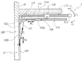
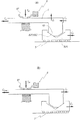
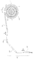
ここで図面を参照すると、特に図1乃至5に示される設備は、車庫ドア100が垂直であり、かつ開口部Oを閉塞する閉止位置と、このドア100が全体として水平である開放位置との間でこのドア100を動かす機構1を備える。ドア100は、組合せ式(sectional)であって、互いに関節接合された複数のパネル102により構成され、またドア100には、開口部Oの両側に設けられた案内部材104内で転動するようになっているローラが備えられている。ドアパネル102の上部パネル102aは、上記機構1により駆動される無端ベルト110により、開口部Oを内部に形成する壁Mに対して直角方向に動かされる往復台108へ、タイバー106を介して接続されている。この往復台108は、ベルト110の下側で固定されており、また往復台108は2つのブラケット114により車庫の天井へ平行に固定されたバー112に沿って摺動する。
Referring now to the drawings, in particular, the equipment shown in FIGS. 1-5 includes a closed position where the
ドア100は、車庫の天井の方向に全体として平行である水平成分M1と、開口部Oを内部に形成する壁Mに対し全体として平行である垂直成分M2とを有する動きを持って移動するように設けられている。
The
ベルト110を駆動するために、ほぼ水平な軸X−X′の回りに回転移動するようにリング4が設けられ、ベルト110は、リング4を約180°にわたり取囲み、密着(adherence)或いは切欠きによって、リング4とともに回転する。
In order to drive the
リング4を軸X−X′の回りに駆動するために電気モータ5が設けられ、電気モータ5はバー112の一端部に取付けられ、かつチューブ7内に収納されている。
An
ドア100の重量を相殺する装置120が設けられ、この相殺装置120はドア100の下部パネル102bに固定された2つのケーブル121と122を備え、これらのケーブル121と122は、ドラム123と124上に、それぞれ巻かれている。これらのドラム123,124は、2つの相殺バネ126と127により取囲まれる同期バー125により連結されており、これらの相殺バネ126及び127の一端部が、同期バー125に固定され、また他端部が、構造体(固定部)に固定されている。このようにして、ドア100の変位の関数として、バネ126と127は、多かれ少なかれ伸張され、ドア100に、そして、ケーブル121と122を通じて、ドア100の重量Pに抗する力F1を加えるのに寄与する。
A
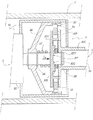
モータ5の出力シャフト53が摩擦ブレーキ8を作動し、その出力側には、リング4を作動させる可逆減速歯車9が取付けられている。
An
このようにして、モータ5の出力シャフト53の動きは、ブレーキ8と減速歯車9とを通じてリング4へ伝達できる。
In this way, the movement of the
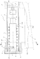
ブレーキ8は、フランス国特許公開公報第2834391号(FR−A−2834391)の技術的教示に従うものであり、モータ5のケーシング51上に固定されるケーシング81を備え、そのケーシング81には、2つのディスク82Aと82Bが内蔵され、これらのディスク82Aと82B間に、半径方向外側への突出部84により、サポート86内に形成された半径方向内側への突出部85と噛合う環状リング83が配設されている。このサポート86は、ケーシング81の内側に固定され、シャフト53に対して回転自在に取付けられ、かつ平行移動について固定されている。バネ87が、ディスク82Aとサポート86をシャフト53に対して不動化するためのサークリップ88との間に介在されている。バネ87は、ディスク82Aとディスク82B上のリング83とに加える傾向を有する力F87を生じ、それにより、ディスク82Bと該ディスク82Bと一体のスリーブ82Cの回転の際に制動トルクC8が生じ、そのスリーブ82C内で、減速歯車9の入力シャフト91が噛合う。トルクC8は、力F87により、およびリング83とディスク82Aおよび82Bとの間の摩擦係数により左右される。初期設定時では、力F87は、最大制動トルクC8maxを生じ、そのトルクにより、ディスク82Aと82Bとの間でリング83を塞ぎ、かくして、固定のケーシング81に対してディスク82Bが不動化される。このようにして、初期設定時では、ブレーキ8は、モータ5と減速歯車9との間、および減速歯車9とモータ5との間の力の伝達に抗する。
The
ピン89が、シャフト53の端部近くでシャフト53の径に沿って取付けられ、そのシャフト53に対して、ディスク82Bが、サークリップ82Dにより平行移動について不動化されている。
A
ディスク82Aには、二重傾斜部82F,82Gを形成する過大厚さ部82Eが設けられ、モータ5がシャフト53を駆動するときに、図4に示されるように、これらの傾斜部82F,82Gへ、ピン89が押付けられる。これは、制動力F87に抗して、サークリップ88の方向にディスク82Aを軸方向にずらす作用を有するので、トルクC8の値の減少により、リング83に対するディスク82Aの摺動と、ディスク82Bに対するリング83の摺動が許容される。このようにして、図4の構成において、ブレーキは、減速歯車9側へのモータ5の動きの伝達をもはや阻止しない。
The
構成部分9、10および4を駆動するためのモータにより生じるトルクC3は、ブレーキ8により生じる制動トルクC8を克服しなければならない。
The torque C 3 generated by the motor for driving the
モータ5と減速歯車9との間に介在されるブレーキ8は、その構造により、一方ではドア100の重量Pにより、他方ではバネ7により加えられるこの重量を相殺する力F1により、リング4が受けるトルクC3の方向と強さの関数として、可変の制動トルクC8を発生することができる。
Due to its structure, the
力F1が、ドア100、ならびに構成部分106、108および110により、リング4へ伝達され、そのリング4に、力F1は、図1において反時計方向のトルクC1の形態で加えられる。重量Pもリング4へ伝達され、そのリング4に、重量Pは、図1に示されるように、時計方向のトルクC2の形態で加えられる。したがって、重量と相殺力との組合せ力は、リング4の部位において、合成トルクC3に変換され、このトルクC3は、トルクC1とC2の相対値に応じて時計方向または反時計方向になり得る。
The force F 1 is transmitted to the ring 4 by the
ドア100が持上げられる際に、トルクC1がトルクC2よりも小さい強さを有すると、ベルト110によりリング4へ加えられるトルクC3は正であると、すなわちバネ126と127による相殺は、ドア100の重量をバランスするには不十分であるとみなすことができる。この場合にドアは、移動を制止されており(braking)、過小相殺または負の相殺と言うことができるであろう。反対に、トルクC1がトルクC2よりも大きい強さを有すると、負荷すなわちドア100およびそれに連結される構成部分は動いている(driving)とみなすことができる。言い換えれば、相殺トルクC1は、ドア100の重量の相殺以上のことをする。これは、過大相殺または正の相殺と言うことができるであろう。この場合にトルクC3は、負であるとみなすことができる。
When the
ドア100が下げられる際、トルクC1がトルクC2よりも大きい値を有すると、ドア100は止まっており、反対の場合は動いている。そのときトルクC3は、正と負の値を、それぞれとる。
When the
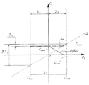
実際には、開口部Oに対するドア100の変位の位置と方向の変化の関数として、トルクC3は、最大正値C3maxと最小負値C3minとの間で変わることができる。Z1は、値C3maxと値C3minとの間でのトルクC3の変化の範囲を示す。Z2は、トルクC3の正の変化の範囲を示し、またZ3は、そのトルクの負の変化の範囲を示す。
In practice, the torque C 3 can vary between a maximum positive value C 3max and a minimum negative value C 3min as a function of the change in position and direction of the displacement of the
ブレーキ8のようなブレーキが存在しない場合に、リング4を駆動するためにモータ5が加えなければならないトルクC5は、トルクC3の関数として、図6において直線Δにより全体的に示されるもの、すなわちトルクC3とほぼバランスするトルクである。
The torque C 5 that must be applied by the
特に図5の分図(A)において一層分かるように、負荷が動いているとき、すなわち負荷が、図6においてゾーンZ2にあるとき、モータにより加えられるトルクC5は、ディスク82Aを、図5の分図(A)において右へ向けて動かす働きを有するとみなすことができ、一方、合成トルクC3は、負荷、すなわちドア100および、とりわけリング4を、その図において左へ向けて動かす働きを有するとみなすことができる。これにより、傾斜部82Fと82Gおよびピン89の部位における、図5の分図(A)において上向きで示される変位F2を引起す力の伝達が生じ、この変位は、弾性力F87に抗してブレーキ8のライニングを分離させる働きを有する。この場合にトルクC8は、トルクC3の値の増加に伴って減少する。
As can be seen more particularly in FIG. 5A, when the load is moving, ie when the load is in zone Z 2 in FIG. 6, the torque C 5 applied by the motor causes the
反対に、図5の分図(B)において明らかなように、負荷が動いているならば、トルクC3は、この図において右へ向けられるものとみなすことができ、力F87の作用全体に抗するものは無いので、その結果、ブレーキ8が負荷を完全に制止し、かつ最大でほぼ一定の力C8maxを生じ、その力は、モータ5の方向において特にリング4の力の伝達に抗する。そのときにドア100を駆動するためにモータ5が加えなければならないトルクC5は、制動力すなわちC8maxを克服しなければならない。
On the other hand, as is apparent in the diagram (B) of FIG. 5, if the load is moving, the torque C 3 can be considered to be directed to the right in this figure, and the entire action of the force F 87 is shown. As a result, the
図5の分図(A)の状態において、ブレーキ8の開放トルクは、図6において直線D8のセグメントにより示され、またゾーンZ2において直線Δにより示されるトルクに負荷される。ブレーキにより生じる抵抗トルクC8は、C3の値の関数として、負荷がバランスしている場合に、すなわち相殺が正でも負でもないときに対応する公称の最大値C8maxから、ブレーキ8の開放を生じさせるトルクC3の値C3ouvに対応するゼロ値へ向けて減少する。事実、この作動範囲においてトルクC8は、トルクC3にほぼ反比例する。
In the state of FIG. 5 (A), the release torque of the
ゾーンZ2において、モータ5がリング4を変位させるために加えなければならない力C5は、したがって、直線ΔとD8の合計である太い点線L5の曲線により表されるものとみなすことができる。
In zone Z 2 , the force C 5 that the
ゾーンZ3において、モータがリング4を駆動するために克服しなければならないトルクは、図5の分図(B)を参照して説明したように、力F87による公称トルクC8maxに等しい。この理由は、この範囲において、曲線L5は、水平な直線であり、モータにより加えられるトルクC5が、ほぼ一定であり、C8maxに等しいからである。 In the zone Z 3 , the torque that the motor must overcome to drive the ring 4 is equal to the nominal torque C 8max due to the force F 87 , as explained with reference to the diagram (B) of FIG. This is because, in this range, the curve L 5 is a horizontal straight line, and the torque C 5 applied by the motor is substantially constant and equal to C 8max .
上述のことから、モータが給電されると、ブレーキ8は、負荷を制止するために、実際にはブレーキとしてよりも速度調節手段として作用することが分かる。
From the above, it can be seen that when the motor is supplied with power, the
上述のことに留意すると、モータ5のトルクC5の変動の大きさA5は、ゾーンZ3における、またゾーンZ2の一部にわたるトルクC5のC8maxに等しいほぼ一定の値と、最大駆動負荷C3maxに対するこのトルクC5の最大値C5maxとの間に含まれる。この大きさA5は、ブレーキを備えない機構に対して考慮する必要があろう対応する大きさA′5よりもかなり小さい。
When noted above that the magnitude A 5 of the fluctuation of the torque C 5 of the
したがって本発明は、モータ5が加えなければならないトルクC5の変動の大きさを、非常に大幅に減少することができる。このトルクは、正値を常に有し、これによって、事実上、モータを劣化する危険にさらすことがあろう発電機としてのモータの作用がなくなる。
Thus, the present invention can greatly reduce the amount of torque C 5 variation that the
負荷が無いときのブレーキの滑りに対応するブレーキの摩擦トルクC8maxと、ブレーキのライニングが分離する瞬間にブレーキへ加えられるブレーキの開放トルクC3ouvとを区別することが可能である。ブレーキの摩擦トルクは、ゾーンZ3においてモータが加えなければならないトルクC5の値に対応する。 It is possible to distinguish between the brake friction torque C 8max corresponding to the brake slip when there is no load and the brake release torque C 3ouv applied to the brake at the moment when the brake lining is separated. Friction torque of the brake correspond to the value of the torque C 5 must motors added in the zone Z 3.
ブレーキ8の摩擦トルクC8maxは、モータの公称トルクにほぼ等しい値に、好都合には選択され、これにより、トルクの変動、したがってドアの移動中におけるドアの速度の変動をさらに最小化することができる。
The friction torque C 8max of the
本発明によれば、ドアの移動の速度は、既知の装置におけるよりも一定であり、急な動きとはね上がりが避けられる。モータは、発電機としてもはや機能しないので、電気的リスクが減少される。特に、モータが非同期モータであるならば、モータが停止するおそれは無い。 According to the present invention, the speed of the door movement is more constant than in known devices, avoiding sudden movements and jumps. Since the motor no longer functions as a generator, the electrical risk is reduced. In particular, if the motor is an asynchronous motor, there is no possibility that the motor will stop.
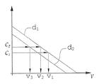
モータが直流モータであるならば、より単純で安価な電源、特に所謂「不可逆的」電源、および/または電圧調節された電源を使用できる。所謂「不可逆的」電源は、モータから送られる逆電流に耐えることができなければならない所謂「可逆的」電源よりも信頼性があり、かつ経済的である。加えて、電圧調節電源により、モータの回転速度と、加えられたトルクとの間の関係を、たとえば、図7に示されるように反比例の関係に定めることができる。そのような電源により、ブレーキの摩擦トルクを減少でき、および負の相殺のゾーンZ2で、駆動トルクの僅かな変動を保持しながら、モータの寸法を最適化できる。したがって、ドアの一定の移動が、既知の装置におけるよりも小形で低出力のモータを使用して得られる。加えて、設備は、信頼度が高いものにされる。 If the motor is a direct current motor, a simpler and less expensive power supply, in particular a so-called “irreversible” power supply and / or a voltage regulated power supply can be used. So-called “irreversible” power supplies are more reliable and economical than so-called “reversible” power supplies that must be able to withstand reverse currents sent from the motor. In addition, the relationship between the rotational speed of the motor and the applied torque can be set to an inversely proportional relationship as shown in FIG. Such power can reduce the friction torque of the brake, and the zone Z 2 negative offset, while maintaining the slight fluctuation of the drive torque can be optimized dimensions of the motor. Thus, constant movement of the door is obtained using a smaller, lower power motor than in known devices. In addition, the equipment is made highly reliable.
図7から特に一層明らかなように、直流モータの電圧調節電源により、ドアの移動の速度v1及びv2の値と、トルクc1及びc2の値との間に所定の関係を維持することができる。事実、対応する対の値v1、c1およびv2、c2は、図7において、所定の直線d1上に位置しなければならない。トルクが値c1からc2へ移行する際、対応する点が図7において別の直線d2上に位置する場合、すなわち非調節電源のような場合に対応する値v3まで速度が減少するおそれを伴うことなく、速度は値v1からv2へと移行する。このように、v1からv2への速度変化は、v1からv3への非調節電源の場合におけるよりも、調節された電源の場合においては僅かである。 As is particularly clear from FIG. 7, a predetermined relationship is maintained between the values of the door movement speeds v 1 and v 2 and the values of the torques c 1 and c 2 by the voltage adjusting power source of the DC motor. be able to. In fact, the corresponding pair of values v 1 , c 1 and v 2 , c 2 must lie on the predetermined straight line d 1 in FIG. When the torque shifts from the value c 1 to c 2 , the speed decreases to a value v 3 corresponding to the case where the corresponding point is located on another straight line d 2 in FIG. Without fear, the speed shifts from the value v 1 to v 2 . Thus, the change in speed from v 1 to v 2 is less with a regulated power supply than with an unregulated power supply from v 1 to v 3 .
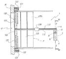
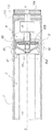
図8と9に示される本発明の第2の実施形態において、第1の実施態様と同様な構成部分は、同一の参照番号が付されている。この機構1は、モータ5が、建物のメーソンリー(masonry)部分へ固定されたブラケット6に取付けられており、モータ5が、該モータ5によりリング4を介して軸X−X′の回りに回転駆動されるチューブ7の内側に収納される点で、上述の機構とは異なる。ストラップS1とS2は、チューブ7の軸X−X′回りの回転位置の関数としてチューブ7の回りに多かれ少なかれ巻かれ、これらのストラップS1とS2は、ドア100の上部パネル102aに固定されている。相殺バネ127が、モータ5のケーシング51の回りに、チューブ7の内側で取付けられている。バネ127の第1の端部127aは、ケーシング51上に設けられた留め具52を取囲み、一方、その第2の端部127bは、適切な手段により、特に、チューブ7に形成された穴71に導入することによりチューブ7へ固定されている。このようにして、チューブ7の回転およびドア100の移動の関数として、バネ127は、このチューブ7及び該チューブ7と強固に連結されたリング4に、ドア100の重量PによりストラップS1とS2によって同チューブ7に加えられるトルクC2に抗するトルクC1を加える。C3は、トルクC1とC2の合計を指す。
In the second embodiment of the present invention shown in FIGS. 8 and 9, the same reference numerals are given to components similar to those in the first embodiment. In this
上述のように、ブレーキ8が、モータ5と、リング4を作動させる減速歯車9との間に設置され、このブレーキ8は、第1の実施態様のものと同一の機能を有し、かつトルクC3の強さと方向の関数として変化する制動力を生じる。
As described above, the
ブレーキ8は、第1の実施態様のものと同一のタイプのものでも異なるタイプのものでもよい。
The
特に、図8において破線で示されるように、トルクC3の方向を求めるために、そしてドア100が止まっているか動いているかを知ることができるようにするために、センサ201を、リング4の近くにおいて機構1に組込むことができる。センサ201からの電気出力信号S201は次いでブレーキ8へ入力され、それにより、この場合に好都合には電磁式のものであるブレーキ8により加えられる制動力を電気的に調節できる。
In particular, as indicated by the dashed line in FIG. 8, in order to determine the direction of torque C 3 and to be able to know whether the
本発明は、組合せ式ドア100について示してきたが、あらゆるタイプのドア、特に、突出部の有無に関係なく強固なフレームを有する車庫ドアに適用できる。
Although the present invention has been described with respect to the
本発明を、フランス国特許公開公報第2834391号(FR−A−2834391)から知られる型式のブレーキについて示してきた。しかしながら、本発明は、ドイツ国特許公報第909274号(DE−C−909274)、ドイツ国特許公報第834714号(DE−C−834714)、フランス国特許公開公報第2720806号(FR−A−2720806)、イタリア国公報第BO―92U000009号(IT−BO−92U000009)から、または欧州特許公開公報第1326000号(EP−A−1326000)から知られるもののようなブレーキについても実施できる。こら例外の他のブレーキ構造も、本発明の範囲内で考えることができる。特に、ブレーキにより加えられる制動力は、必ずしもトルクである必要はない。 The invention has been shown for a brake of the type known from French Patent Publication No. 2834391 (FR-A-283391). However, the present invention relates to German Patent Publication No. 909274 (DE-C-909274), German Patent Publication No. 835714 (DE-C-83714), French Patent Publication No. 2720806 (FR-A-2720806). ), Brakes such as those known from Italian publication No. BO-92U000009 (IT-BO-92U000009) or from European patent publication No. 1326000 (EP-A-1326000). Other brake structures with these exceptions are also contemplated within the scope of the present invention. In particular, the braking force applied by the brake is not necessarily torque.
上述の様々な実施態様の技術的特徴を、本発明の範囲内で互いに組合せることもできる。 The technical features of the various embodiments described above can also be combined with each other within the scope of the invention.
1 機構
4 リング(部材)
5 電気モータ
8 ブレーキ
82A,82B ディスク(可動ライニング)
83 リング (可動ライニング)
100 ドア
126、127 相殺バネ(相殺手段)
201 センサ
1 Mechanism 4 Ring (member)
5
83 Ring (movable lining)
100
201 sensor
Claims (13)
電気モータ(5)と、
前記モータにより駆動され、かつ前記ドア(100)に運動的に連結される部材(4)と、
前記ドアの重量(P)により前記部材に加えられるトルク(C2)を少なくとも部分的に相殺(C1)する手段(126、127)とを有し、
当該機構は、前記モータ(5)と前記部材(4)との間に介在されたブレーキ(8)を備え、該ブレーキ(8)は、前記ドア(100)の少なくとも移動段階において、制動力(C8)を前記モータに対して加え、その場合前記ドアの重量(P)と前記相殺手段(126、127)により加えられる力(F1、C1)との組合せ力(C3)が前記部材(4)を前記モータ(5)と同一の方向に変位させる働きを有することを特徴とする機構。 A mechanism for operating a door that moves at least partially vertically,
An electric motor (5);
A member (4) driven by the motor and movably connected to the door (100);
Means (126, 127) for at least partially canceling (C 1 ) the torque (C 2 ) applied to the member by the weight (P) of the door;
The mechanism includes a brake (8) interposed between the motor (5) and the member (4), and the brake (8) has a braking force (at least at a moving stage of the door (100)). C 8 ) is applied to the motor, in which case the combined force (C 3 ) of the weight (P) of the door and the force (F 1 , C 1 ) applied by the canceling means (126, 127) is A mechanism having the function of displacing the member (4) in the same direction as the motor (5).
The braking force (C 8 ) includes the weight (P) of the door (100) and the weight when the combined force (C 3 ) has a function of displacing the member in the direction opposite to the motor (5). It characterized by having a substantially inversely proportional to the value the force to cancel (F 1, C 1) and a combination force of (C 3) the method of claim 12.
Applications Claiming Priority (1)
| Application Number | Priority Date | Filing Date | Title |
|---|---|---|---|
| FR0403383A FR2868460B1 (en) | 2004-03-31 | 2004-03-31 | MECHANISM FOR MANEUVERING A DOOR, USE OF A BRAKE IN SUCH A MECHANISM AND METHOD FOR CONTROLLING A MOTOR TORQUE IN SUCH A MECHANISM |
Publications (1)
| Publication Number | Publication Date |
|---|---|
| JP2005290979A true JP2005290979A (en) | 2005-10-20 |
Family
ID=34878475
Family Applications (1)
| Application Number | Title | Priority Date | Filing Date |
|---|---|---|---|
| JP2005098676A Pending JP2005290979A (en) | 2004-03-31 | 2005-03-30 | Mechanism for operating door, use of brake in the mechanism, and method for adjusting driving torque in the mechanism |
Country Status (9)
| Country | Link |
|---|---|
| US (1) | US20050217806A1 (en) |
| EP (1) | EP1582681B1 (en) |
| JP (1) | JP2005290979A (en) |
| CN (1) | CN1676861B (en) |
| AT (1) | ATE430243T1 (en) |
| AU (1) | AU2005201360B8 (en) |
| DE (1) | DE602005014162D1 (en) |
| ES (1) | ES2249201T3 (en) |
| FR (1) | FR2868460B1 (en) |
Families Citing this family (13)
| Publication number | Priority date | Publication date | Assignee | Title |
|---|---|---|---|---|
| ITTV20060007A1 (en) * | 2006-01-24 | 2007-07-25 | Nice Spa | BRAKE CLUTCH DEVICE |
| ITTV20060006A1 (en) * | 2006-01-24 | 2007-07-25 | Nice Spa | SUPPORT FOR A BRAKE ELEMENT |
| ITTV20060008A1 (en) * | 2006-01-24 | 2007-07-25 | Nice Spa | METHOD FOR HANDLING A ROLLER WITH A SPEED OF CONTROLLED ALONG A ROUTE OF CLIMBING OR DESCENT AND ITS OPERATION |
| US7578540B2 (en) * | 2006-08-11 | 2009-08-25 | Actuall Doorlift Systems B.V. | Vehicle sliding door actuator |
| FR2908244A1 (en) | 2006-11-02 | 2008-05-09 | Somfy Sas | DOMOTIC ACTUATOR COMPRISING AN ASYNCHRONOUS ELECTRIC MOTOR WITH VARIABLE ROTATION SPEED |
| FR2918223B1 (en) * | 2007-06-29 | 2017-05-19 | Somfy Sas | DOMOTIC ACTUATOR COMPRISING A TORQUE TRANSMISSION BRAKE |
| FR2922384B1 (en) | 2007-10-16 | 2009-11-27 | Somfy Sas | METHOD FOR DETERMINING AN INTERNAL SIZE OF A MANEUVER ACTUATOR OF A DOMOTIC MOBILE ELEMENT |
| CN103161345B (en) * | 2012-11-28 | 2016-06-01 | 安徽鸿路钢结构(集团)股份有限公司 | Comb fork handing-over displacement high density perpendicular lift parking apparatus |
| CN104033092B (en) * | 2014-06-16 | 2015-10-07 | 韦智生 | A kind of double window with built-in curtain |
| AU2018363644B2 (en) | 2017-11-08 | 2024-08-29 | Assa Abloy Entrance Systems Ab | High speed overhead door |
| IT201800006078A1 (en) * | 2018-06-06 | 2019-12-06 | GUIDE AND SUPPORT DEVICE FOR A FURNITURE DOOR WITH FOLDING DOWNWARD OPENING | |
| CN109736675B (en) * | 2019-03-21 | 2024-07-23 | 佛山市软创科技有限公司 | Upturning device for upturning door and upturning door storage cabinet |
| US20260002399A1 (en) * | 2024-07-01 | 2026-01-01 | Gmi Holdings, Inc. | Cable drum cable tensioner and methods in a movable barrier system |
Family Cites Families (35)
| Publication number | Priority date | Publication date | Assignee | Title |
|---|---|---|---|---|
| US2064470A (en) * | 1931-01-17 | 1936-12-15 | Richards Wilcox Mfg Co | Overhead door |
| DE834714C (en) | 1948-10-02 | 1952-03-24 | Albrecht Reusch Dipl Ing | Braking device for electric motor drives |
| DE909274C (en) | 1951-06-29 | 1954-04-15 | Kurt Henze | Automatically applied cone brake when torque fails |
| US3471971A (en) * | 1967-09-28 | 1969-10-14 | Moscow K Richmond | Door operator |
| US3481074A (en) * | 1968-02-01 | 1969-12-02 | Eaton Yale & Towne | Door opener |
| US3722141A (en) * | 1971-05-28 | 1973-03-27 | Vemco Products | Overhead door operator release |
| US3955661A (en) * | 1972-06-28 | 1976-05-11 | Lsb Industries, Inc. | Apparatus for opening and closing door members and the like |
| US4231191A (en) * | 1978-06-12 | 1980-11-04 | Challenger, Inc. | Automatic door opener system |
| DE10244653A1 (en) * | 2002-09-25 | 2004-04-08 | Hörmann KG Antriebstechnik | Door with gate operator and method for assembling the same |
| DE3301446C2 (en) * | 1983-01-18 | 1985-05-15 | Hörmann KG Antriebs- und Steuerungstechnik, 4834 Harsewinkel | Gate operator |
| US4931708A (en) * | 1989-10-05 | 1990-06-05 | Thore Johnsen | Independent band spring door gear motor operator |
| WO1992018999A1 (en) * | 1991-04-09 | 1992-10-29 | The Chamberlain Group, Inc. | Garage door operator safety apparatus |
| US5277373A (en) * | 1991-12-18 | 1994-01-11 | Morton Henry H | Apparatus and method for controlling tension in a moving material |
| IT227599Y1 (en) | 1992-01-20 | 1997-12-15 | R L As As | BRAKE DEVICES FOR ROLLER BLINDS |
| CA2124222C (en) * | 1994-05-20 | 1998-10-13 | Raymond Wandio | Overhead door opener |
| FR2720806B1 (en) | 1994-06-03 | 1997-11-21 | Leroy Somer Moteurs | Braking device for a rotary shaft, motor and apparatus comprising such a device. |
| ATE233363T1 (en) * | 1996-05-22 | 2003-03-15 | Becker Antriebe Gmbh | CONTROL FOR GATES DRIVES |
| US5979587A (en) * | 1997-06-06 | 1999-11-09 | Ford Global Technologies, Inc. | Electrically assisted power steering apparatus |
| US6092582A (en) * | 1999-03-10 | 2000-07-25 | Liu; Kuei-Chang | Motor drive for an electric rolling steel door |
| US6382005B1 (en) * | 1999-10-18 | 2002-05-07 | Bryan A. White | Garage door locking apparatus |
| US6742564B2 (en) * | 2000-04-12 | 2004-06-01 | Martin Door Manufacturing, Inc. | Spring force safety locking system for sectional doors |
| US6388412B1 (en) * | 2000-05-09 | 2002-05-14 | Overhead Door Corporation | Door operator control system and method |
| US6374543B1 (en) * | 2000-06-06 | 2002-04-23 | Magdy N. Bishai | Door opener apparatus with power transfer mechanism |
| US6289963B1 (en) * | 2000-06-16 | 2001-09-18 | Kent J. Vaske | Dual closure system for overhead doors |
| US6346889B1 (en) * | 2000-07-01 | 2002-02-12 | Richard D. Moss | Security system for automatic door |
| DE20217608U1 (en) * | 2001-11-22 | 2003-03-06 | Rademacher Geräte-Elektronik GmbH & Co. KG, 46414 Rhede | Tubular motor drive assembly |
| FR2834391B1 (en) | 2001-12-28 | 2004-04-02 | Somfy | DISC BRAKE AND TORQUE TRANSMISSION DEVICE |
| FR2837865B1 (en) * | 2002-03-28 | 2005-07-29 | Simu | MANUFACTURING MECHANISM AND CLOSURE OR SOLAR PROTECTION INSTALLATION INCORPORATING SUCH A DEVICE |
| US20040020612A1 (en) * | 2002-04-17 | 2004-02-05 | Giuseppe Bosio | Ceiling actuator for up-and-over and sectional doors |
| US7686061B2 (en) * | 2002-04-24 | 2010-03-30 | Overhead Door Corporation | Winding assembly for door counterbalance system |
| US6883579B2 (en) * | 2002-05-09 | 2005-04-26 | The Chamberlain Group, Inc. | Drive system for garage door |
| US20030209333A1 (en) * | 2002-05-09 | 2003-11-13 | The Chamberlain Group, Inc. | Drive system for garage door |
| EP1462601B1 (en) * | 2003-03-22 | 2018-01-10 | Novoferm GmbH | Sectional door |
| CA2483356C (en) * | 2004-10-26 | 2009-04-07 | Jay Chung-Chieh Wu | Direct transmission garage door opener |
| US8113263B2 (en) * | 2005-06-30 | 2012-02-14 | Overhead Door Corporation | Barrier operator with magnetic position sensor |
-
2004
- 2004-03-31 FR FR0403383A patent/FR2868460B1/en not_active Expired - Fee Related
-
2005
- 2005-03-29 US US11/091,543 patent/US20050217806A1/en not_active Abandoned
- 2005-03-30 DE DE602005014162T patent/DE602005014162D1/en not_active Expired - Lifetime
- 2005-03-30 AU AU2005201360A patent/AU2005201360B8/en not_active Ceased
- 2005-03-30 JP JP2005098676A patent/JP2005290979A/en active Pending
- 2005-03-30 AT AT05356055T patent/ATE430243T1/en not_active IP Right Cessation
- 2005-03-30 ES ES05356055T patent/ES2249201T3/en not_active Expired - Lifetime
- 2005-03-30 EP EP05356055A patent/EP1582681B1/en not_active Expired - Lifetime
- 2005-03-31 CN CN2005100598209A patent/CN1676861B/en not_active Expired - Fee Related
Also Published As
| Publication number | Publication date |
|---|---|
| CN1676861A (en) | 2005-10-05 |
| US20050217806A1 (en) | 2005-10-06 |
| EP1582681A1 (en) | 2005-10-05 |
| ATE430243T1 (en) | 2009-05-15 |
| ES2249201T1 (en) | 2006-04-01 |
| AU2005201360B8 (en) | 2011-03-10 |
| DE602005014162D1 (en) | 2009-06-10 |
| AU2005201360A1 (en) | 2005-10-20 |
| CN1676861B (en) | 2011-03-16 |
| FR2868460B1 (en) | 2008-01-11 |
| ES2249201T3 (en) | 2009-06-30 |
| AU2005201360B2 (en) | 2010-11-11 |
| EP1582681B1 (en) | 2009-04-29 |
| FR2868460A1 (en) | 2005-10-07 |
Similar Documents
| Publication | Publication Date | Title |
|---|---|---|
| JP2005290979A (en) | Mechanism for operating door, use of brake in the mechanism, and method for adjusting driving torque in the mechanism | |
| CA2284953C (en) | Method and apparatus for regulating the closing speed of a rolling fire door | |
| WO2016194641A1 (en) | Braking device, and shielding device equipped with same | |
| KR102181149B1 (en) | Open and shut apparatus for door closure fire door | |
| JP2013189859A (en) | Opening/closing body stop device of opening/closing device | |
| JP5585218B2 (en) | Elevator door control device | |
| JP5175186B2 (en) | Drive unit for moving parts of furniture | |
| JP5893494B2 (en) | Automatic closing device for sliding door | |
| JP4231848B2 (en) | Motor drive control device | |
| JPH08246744A (en) | Sliding door closer device | |
| JP6704285B2 (en) | blind | |
| JP5107698B2 (en) | Roll screen | |
| JP2010007408A (en) | Door having tension spring counter weight, and its actuator | |
| JPH0867474A (en) | Wind pressure trouble compensator of elevator | |
| JP5188375B2 (en) | Sliding door device | |
| WO2009081827A1 (en) | Brake for sliding door | |
| JP4294527B2 (en) | Seat elevating control device in entrance / exit seat opening / closing machine | |
| JP6438918B2 (en) | Braking device and solar shading device using the same | |
| JP2955933B1 (en) | Lower limit stop for fabric fire shutter | |
| JP6978535B2 (en) | Impact mitigation device attached to the overhead door and the overhead door equipped with it | |
| JP5730478B2 (en) | Shutter device | |
| JPH1150736A (en) | Door closer | |
| JP2010285241A (en) | Elevator damping device | |
| JPH0726600U (en) | Speed governor such as shutter | |
| JP4519160B2 (en) | Sliding door self-closing device |