JP2005290942A - Vertically moving underwater membrane - Google Patents
Vertically moving underwater membrane Download PDFInfo
- Publication number
- JP2005290942A JP2005290942A JP2004132197A JP2004132197A JP2005290942A JP 2005290942 A JP2005290942 A JP 2005290942A JP 2004132197 A JP2004132197 A JP 2004132197A JP 2004132197 A JP2004132197 A JP 2004132197A JP 2005290942 A JP2005290942 A JP 2005290942A
- Authority
- JP
- Japan
- Prior art keywords
- underwater
- float
- ring
- auxiliary
- guide pole
- Prior art date
- Legal status (The legal status is an assumption and is not a legal conclusion. Google has not performed a legal analysis and makes no representation as to the accuracy of the status listed.)
- Granted
Links
- 239000012528 membrane Substances 0.000 title abstract description 16
- XLYOFNOQVPJJNP-UHFFFAOYSA-N water Substances O XLYOFNOQVPJJNP-UHFFFAOYSA-N 0.000 claims abstract description 15
- 239000002184 metal Substances 0.000 description 9
- 238000000034 method Methods 0.000 description 3
- 229920001875 Ebonite Polymers 0.000 description 1
- 238000003780 insertion Methods 0.000 description 1
- 230000037431 insertion Effects 0.000 description 1
- 239000004576 sand Substances 0.000 description 1
Images

Landscapes
- Cleaning Or Clearing Of The Surface Of Open Water (AREA)
Abstract
Description
本発明は、水位の変化により上下に可動可能な水中膜に関する。 The present invention relates to an underwater film that is movable up and down by a change in water level.
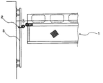
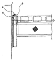
従来、ポンプ所・取水口・沈砂池等に展張されている水位の変化により上下に可動するオイルフェンス1等は、オイルフェンスの上部近傍にリング2を設け、このリングを護岸等に設けられたガイドポール3に挿通して設置されていた(図1参照)。また他の方法として護岸等に設けられた中空管4を用い、該中空管に垂直にスリット状の切り欠き部5を設け、該中空管内を摺動可能なフロート状金具6をオイルフェンス1の両端部に設けた装置が知られている(図2参照)。
さらに、水中膜の上部近傍部の両端部に、水中膜に対してそれぞれ直角方向(二方向)にアームを設け、該アームに補助フロートを設け、かつ前記水中膜の上部近傍部の両端部にリングを設け、該リングを、ガイドポールに挿通し、該ガイドポールを護岸等に固定してなる装置が知られている。
しかしながら図1のような装置はリングの重みで長時間の間に水平位置が保たれずに垂れさがった状態になり、また水流により水中膜が傾斜することによってリングが斜めになることからガイドポールとの間に摩擦力が増大して結果的にリングがガイドポールに引っかかる状態となり、水位の変化によって水中膜が上下に可動することが不可能となる欠点があった。
また、図2のような装置はフロート状金具6の浮力を増す方法として、フロート状金具6を長くすることや径を大きくすることが上げられるが、フロート状金具6を長くすると金具の重量が大きくなり、その結果、浮力の増加が小さいことや、該中空管4内のフロート状金具6がつかえる状態となり、水位の変化によって水中膜が上下に可動することが不可能となる。フロート状金具6の径を大きくすると浮力は増加するが、該中空管4の径も大きくなり、高価格になる欠点があった。Conventionally, an
Furthermore, an arm is provided at both ends of the vicinity of the upper portion of the underwater membrane in a direction perpendicular to the underwater membrane (two directions), an auxiliary float is provided on the arm, and both ends of the upper vicinity of the underwater membrane are provided. There is known an apparatus in which a ring is provided, the ring is inserted into a guide pole, and the guide pole is fixed to a revetment or the like.
However, the device as shown in FIG. 1 is in a state where the horizontal position is not maintained for a long time due to the weight of the ring, and the ring is inclined due to the inclination of the underwater film due to the water flow. As a result, the frictional force increases and as a result, the ring is caught on the guide pole, and the underwater film cannot be moved up and down due to the change in the water level.
Further, in the apparatus as shown in FIG. 2, as a method of increasing the buoyancy of the float metal fitting 6, it is possible to increase the length of the float metal fitting 6 or increase the diameter. As a result, the increase in buoyancy is small, and the float-like metal fitting 6 in the
そこで本発明者は、急激な水位上昇によっても水中膜に設けられたリングがガイドポールに引っかからず、水中膜が上下にスムーズに可動する水中膜について種々研究を重ねた結果本発明を完成するに至った。 Therefore, the present inventor has completed various studies on the underwater film in which the ring provided in the underwater film is not caught by the guide pole even when the water level is suddenly increased and the underwater film moves smoothly up and down. It came.
すなわち、本発明は、水中膜の上部近傍部の両端部に、水中膜に対してそれぞれ直角方向にアームを設け、該アームに補助フロートを設け、かつ前記水中膜の上部近傍部の両端部にリングを設け、該リングをガイドポールに挿通し、さらに該リングの下部に補助ブイをガイドポールに挿通して設け、前記ガイドポールを壁面等に固定してなる、水位の変化によって上下に可動可能な水中膜である。 That is, the present invention provides an arm in the direction perpendicular to the underwater film at both ends near the upper part of the underwater film, an auxiliary float on the arm, and both ends near the upper part of the underwater film. A ring is provided, the ring is inserted through the guide pole, and an auxiliary buoy is inserted through the guide pole at the bottom of the ring. The guide pole is fixed to the wall, etc. It is an underwater film.
本発明方法によれば、水中膜は急激な水位上昇、また上下可動する場合にガイドポール3にリング18が引っかかることもなく水位の変化に応じてスムーズに上下動を行うことができる。
また使用する補助ブイは、既設のガイドポール等を改良することなく設置が可能で、補助ブイも安価である。According to the method of the present invention, the underwater film can move up and down smoothly in response to a change in the water level without a
The auxiliary buoy to be used can be installed without improving the existing guide pole and the like, and the auxiliary buoy is also inexpensive.
次に本発明をさらに詳細に説明するために図面を参照しながら説明するが、本発明は以下の説明のみに限定されるものではない。 Next, the present invention will be described in more detail with reference to the drawings. However, the present invention is not limited to the following description.
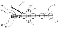
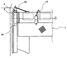
図3Bは、本発明に係る水中膜の一部を切り欠いた端部部分の側面図を示す。本発明の水中膜7は多数のフロート8をテンションゴムベルト9で挾着してフロート部10を構成し、このフロート部10の下部にカーテン11を一体に設ける。フロート部10の両端部(図3は左側部のみ)には取付金具12によって該フロート部を挾持するように設ける。
フロート部10に補助フロート体13を設ける。このフロート体13は、中心部にパイプ挿通口14を有し、そこにパイプ15を挿入する。このように構成したパイプ15の上、下端をL字状のアーム16の一端の直線部に一体に設け、そのL字状のアーム16の他端の屈曲部をテンションベルト9に例えばボルトナットで一体に設ける。FIG. 3B shows a side view of an end portion in which a part of the underwater membrane according to the present invention is cut away. In the underwater membrane 7 of the present invention, a large number of floats 8 are attached by
An
本発明の水中膜はその両端部の取付金具12にシャックル17を設け、このシャックル17にリング18を設け、このリング18の下部に補助ブイ19をガイドポール3に挿通して設ける。このように設けることによって補助ブイ19が常にリング18を水平状態で押し上げ、リング18の垂れ下がりを防止する。 In the underwater membrane of the present invention,
本発明の水中膜はリング18の下部に補助ブイ19を設けることによって、リング18を水平に保ちガイドポール3とリング18との間の摩擦力を減らし、結果的にリング18がガイドポール3に引っかからずに、急激な水位上昇においても可動可能な水中膜とすることができる。 In the underwater membrane of the present invention, the
本発明の水中膜はシャックル17を鎖21によって取付金具12に連結することによってシャックル17の上下の変動を制御することができる。 The underwater membrane of the present invention can control the vertical fluctuation of the
本発明の水中膜は水面上の浮遊物を岸壁と水中膜の隙間からの流出を防止するために例えば移流フィン22を岸壁等に設ける。
尚、この移流フィン22は、水中膜7のフロート8の一部と常に接している構造で、硬質性のゴムと軟質性のゴムを組み合わせたものが良い。The underwater film of the present invention is provided with, for example,
The
図3Bでは補助ブイ19を1個装着する場合を示したが、複数個を多段に装着することもできる。これらの補助ブイ19は球状、楕円状、円筒状それぞれ異なる形状のものも使用することができる。 Although FIG. 3B shows a case where one
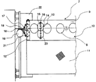
図4では補助ブイ19は、護岸等に設けられた該中空管4内を摺動可能なフロート状金具6を挿入し、フロート状金具6の下部に置くこともできる。フロート状金具6の下部に補助ブイ19置くことでフロート状金具6の重量を増すことなく、浮力だけを増加することができ、既設の設備を変えることなく、安価に改良できる。
尚、取付金具12に補助フロート体13を設けてもよい。In FIG. 4, the
An
図5では護岸等に移流フィン22を設け、水面上の浮遊物が該中空管4と摺動可能なフロート状金具6の隙間に入り込みを防止することで、水位の変化によって水中膜が上下に可動することとなる。
また、オイルフェンス1に補助フロート体13を設けてもよい。In FIG. 5,
Further, the
8・・・・・フロート
9・・・・・テンションゴムベルト
11・・・・・カーテン
18・・・・・リング
19・・・・・補助ブイ
20・・・・・補助フロート8 ... Float 9 ...
Claims (1)
Priority Applications (1)
| Application Number | Priority Date | Filing Date | Title |
|---|---|---|---|
| JP2004132197A JP4714824B2 (en) | 2004-03-31 | 2004-03-31 | Up and down movable underwater membrane mooring device |
Applications Claiming Priority (1)
| Application Number | Priority Date | Filing Date | Title |
|---|---|---|---|
| JP2004132197A JP4714824B2 (en) | 2004-03-31 | 2004-03-31 | Up and down movable underwater membrane mooring device |
Publications (2)
| Publication Number | Publication Date |
|---|---|
| JP2005290942A true JP2005290942A (en) | 2005-10-20 |
| JP4714824B2 JP4714824B2 (en) | 2011-06-29 |
Family
ID=35324182
Family Applications (1)
| Application Number | Title | Priority Date | Filing Date |
|---|---|---|---|
| JP2004132197A Expired - Lifetime JP4714824B2 (en) | 2004-03-31 | 2004-03-31 | Up and down movable underwater membrane mooring device |
Country Status (1)
| Country | Link |
|---|---|
| JP (1) | JP4714824B2 (en) |
Citations (9)
| Publication number | Priority date | Publication date | Assignee | Title |
|---|---|---|---|---|
| JPS4810840U (en) * | 1971-06-16 | 1973-02-07 | ||
| JPS52140249U (en) * | 1976-04-20 | 1977-10-24 | ||
| JPS53137475A (en) * | 1977-05-06 | 1978-11-30 | Eikou Sangiyou Kk | Apparatus for collecting floating material |
| JPS5477528U (en) * | 1977-11-11 | 1979-06-01 | ||
| JPS56116432U (en) * | 1980-02-08 | 1981-09-07 | ||
| JPS63140865U (en) * | 1987-03-05 | 1988-09-16 | ||
| JPH02243814A (en) * | 1989-03-16 | 1990-09-27 | Sumitomo Rubber Ind Ltd | Prevention device for diffusion of dirty liquid |
| JPH0813457A (en) * | 1994-06-29 | 1996-01-16 | Masanobu Kodera | Collecting device for effluent oil |
| JP2002309564A (en) * | 2001-04-13 | 2002-10-23 | Sumitomo Rubber Ind Ltd | Anti-pollution membrane |
-
2004
- 2004-03-31 JP JP2004132197A patent/JP4714824B2/en not_active Expired - Lifetime
Patent Citations (9)
| Publication number | Priority date | Publication date | Assignee | Title |
|---|---|---|---|---|
| JPS4810840U (en) * | 1971-06-16 | 1973-02-07 | ||
| JPS52140249U (en) * | 1976-04-20 | 1977-10-24 | ||
| JPS53137475A (en) * | 1977-05-06 | 1978-11-30 | Eikou Sangiyou Kk | Apparatus for collecting floating material |
| JPS5477528U (en) * | 1977-11-11 | 1979-06-01 | ||
| JPS56116432U (en) * | 1980-02-08 | 1981-09-07 | ||
| JPS63140865U (en) * | 1987-03-05 | 1988-09-16 | ||
| JPH02243814A (en) * | 1989-03-16 | 1990-09-27 | Sumitomo Rubber Ind Ltd | Prevention device for diffusion of dirty liquid |
| JPH0813457A (en) * | 1994-06-29 | 1996-01-16 | Masanobu Kodera | Collecting device for effluent oil |
| JP2002309564A (en) * | 2001-04-13 | 2002-10-23 | Sumitomo Rubber Ind Ltd | Anti-pollution membrane |
Also Published As
| Publication number | Publication date |
|---|---|
| JP4714824B2 (en) | 2011-06-29 |
Similar Documents
| Publication | Publication Date | Title |
|---|---|---|
| WO2006073931B1 (en) | Catenary line dynamic motion suppression | |
| CN102582794A (en) | Buoyant device and floating system | |
| JP2011032940A (en) | Installation structure of hydraulic power generating apparatus | |
| AU2019271729A1 (en) | System and method for controlling a structure suspended in water | |
| CN111762412A (en) | Barrel and anti-shaking device in barrel | |
| US20090202303A1 (en) | Enhanced wave power generators | |
| JP4714824B2 (en) | Up and down movable underwater membrane mooring device | |
| JP6966393B2 (en) | Mooring system | |
| CN202508263U (en) | Floating device and system | |
| KR101018303B1 (en) | Fountain buoyancy device with adjustable water level | |
| CA2934893C (en) | Attachment flange for buoys and marine fenders | |
| JP2002218860A (en) | Aquaculture cage shape retention device | |
| KR101349860B1 (en) | Oil unloading apparatus | |
| CN102822421A (en) | Foundation structure | |
| JP5022321B2 (en) | Seawater circulation device | |
| JPS62292587A (en) | Underwater floating body for semi-submerged marine structure | |
| SU1314989A1 (en) | Arrangement for hoisting deep water to surface layers of water basin | |
| KR102136490B1 (en) | Apparatus for generating electricity using flow of sea water | |
| JPS598956Y2 (en) | mooring device | |
| JP2660678B2 (en) | Floating seawater exchange device | |
| JP2012132141A (en) | Columnar structure and method of extending columnar structure at sea bottom | |
| JP4832047B2 (en) | Mooring equipment | |
| KR101629849B1 (en) | Seebed Mooring Device Collection Apparatus | |
| KR20160085984A (en) | Tension maintenance equipment for mooring of offshore structures | |
| KR200301090Y1 (en) | Fluid flow guide pipe with buoyancy disk coupled to guide the fluid inlet to the upper surface of the fluid |
Legal Events
| Date | Code | Title | Description |
|---|---|---|---|
| A621 | Written request for application examination |
Free format text: JAPANESE INTERMEDIATE CODE: A621 Effective date: 20070222 |
|
| A977 | Report on retrieval |
Free format text: JAPANESE INTERMEDIATE CODE: A971007 Effective date: 20100525 |
|
| A131 | Notification of reasons for refusal |
Free format text: JAPANESE INTERMEDIATE CODE: A131 Effective date: 20100622 |
|
| A521 | Request for written amendment filed |
Free format text: JAPANESE INTERMEDIATE CODE: A523 Effective date: 20100813 |
|
| TRDD | Decision of grant or rejection written | ||
| A01 | Written decision to grant a patent or to grant a registration (utility model) |
Free format text: JAPANESE INTERMEDIATE CODE: A01 Effective date: 20110222 |
|
| A61 | First payment of annual fees (during grant procedure) |
Free format text: JAPANESE INTERMEDIATE CODE: A61 Effective date: 20110228 |
|
| R150 | Certificate of patent or registration of utility model |
Ref document number: 4714824 Country of ref document: JP Free format text: JAPANESE INTERMEDIATE CODE: R150 Free format text: JAPANESE INTERMEDIATE CODE: R150 |
|
| FPAY | Renewal fee payment (event date is renewal date of database) |
Free format text: PAYMENT UNTIL: 20140408 Year of fee payment: 3 |
|
| R250 | Receipt of annual fees |
Free format text: JAPANESE INTERMEDIATE CODE: R250 |
|
| R250 | Receipt of annual fees |
Free format text: JAPANESE INTERMEDIATE CODE: R250 |
|
| R250 | Receipt of annual fees |
Free format text: JAPANESE INTERMEDIATE CODE: R250 |
|
| R250 | Receipt of annual fees |
Free format text: JAPANESE INTERMEDIATE CODE: R250 |
|
| R250 | Receipt of annual fees |
Free format text: JAPANESE INTERMEDIATE CODE: R250 |
|
| R250 | Receipt of annual fees |
Free format text: JAPANESE INTERMEDIATE CODE: R250 |
|
| R250 | Receipt of annual fees |
Free format text: JAPANESE INTERMEDIATE CODE: R250 |
|
| R250 | Receipt of annual fees |
Free format text: JAPANESE INTERMEDIATE CODE: R250 |
|
| R250 | Receipt of annual fees |
Free format text: JAPANESE INTERMEDIATE CODE: R250 |
|
| R250 | Receipt of annual fees |
Free format text: JAPANESE INTERMEDIATE CODE: R250 |
|
| EXPY | Cancellation because of completion of term |