JP2005290924A - Method for forming tube burying groove, jig for forming continuous groove and jig for forming cross groove - Google Patents
Method for forming tube burying groove, jig for forming continuous groove and jig for forming cross groove Download PDFInfo
- Publication number
- JP2005290924A JP2005290924A JP2004111037A JP2004111037A JP2005290924A JP 2005290924 A JP2005290924 A JP 2005290924A JP 2004111037 A JP2004111037 A JP 2004111037A JP 2004111037 A JP2004111037 A JP 2004111037A JP 2005290924 A JP2005290924 A JP 2005290924A
- Authority
- JP
- Japan
- Prior art keywords
- groove
- tube
- burying
- forming
- pipe
- Prior art date
- Legal status (The legal status is an assumption and is not a legal conclusion. Google has not performed a legal analysis and makes no representation as to the accuracy of the status listed.)
- Pending
Links
Images


Landscapes
- Sewage (AREA)
Abstract
【課題】 管埋設溝を複数回に分割して形成するときや、先に形成した管埋設溝に交わるようにして新たな管埋設溝を形成するときに、先に形成された管埋設溝内に土砂が落下することを防止できる管埋設溝の形成方法並びに連続溝形成用治具及び交差溝形成用治具を提供する。
【解決手段】 先に形成した管埋設溝に敷設された暗渠管の端部上方を覆うように連続溝形成用治具を設置した状態で溝形成具による新たな管埋設溝の形成を行い、新たな管埋設溝の終端では溝形成具の下端を傾斜板の上方を通過させて地中から引き抜き、次いで、連続溝形成用治具を溝内から取り出して両管埋設溝同士を連続させる。また、先に形成した管埋設溝に交差溝形成用治具を設置した状態で溝形成具による新たな管埋設溝の形成を行い、新たな管埋設溝を先に形成した管埋設溝に交差させて形成した後、交差溝形成用治具を溝内から取り出して両管埋設溝同士を直交させる。
【選択図】 図1PROBLEM TO BE SOLVED: To form a pipe burying groove formed previously by dividing the pipe burying groove into a plurality of times or when forming a new pipe burying groove so as to intersect with the previously formed pipe burying groove. A method for forming a tube burying groove, a continuous groove forming jig, and a cross groove forming jig that can prevent earth and sand from falling on the surface are provided.
SOLUTION: A new tube burying groove is formed by a groove forming tool in a state in which a continuous groove forming jig is installed so as to cover an upper end portion of a culvert tube laid in a previously formed tube burying groove, At the end of the new pipe burying groove, the lower end of the groove forming tool is passed above the inclined plate and pulled out from the ground, and then the continuous groove forming jig is taken out from the groove and the two pipe burying grooves are made continuous. In addition, with the cross groove forming jig installed in the previously formed tube burying groove, a new tube burying groove is formed by the groove forming tool, and the new tube burying groove intersects the previously formed tube burying groove. Then, the intersecting groove forming jig is taken out from the groove and the both-buried grooves are orthogonalized.
[Selection] Figure 1
Description
本発明は、管埋設溝の形成方法並びに連続溝形成用治具及び交差溝形成用治具に関し、詳しくは、湿地や圃場等の地中に暗渠排水パイプ等を埋設するための管埋設溝を長い距離に連続して形成したり、複数の管埋設溝を交わるように形成したりする方法に関するとともに、管埋設溝を長手方向に複数回に分割して連続形成する際に使用する連続溝形成用治具と、複数の管埋設溝を交わるように形成する際に使用する交差溝形成用治具とに関する。 The present invention relates to a method for forming a pipe burying groove, a continuous groove forming jig, and a cross groove forming jig, and more specifically, a pipe burying groove for burying a culvert drainage pipe or the like in a ground such as a wetland or a farm field. Continuation groove formation to be used when continuously forming a tube embedded groove by dividing it into a plurality of times in the longitudinal direction, as well as a method of continuously forming a long distance or forming a plurality of tube embedded grooves. The present invention relates to a jig for use and a jig for forming a cross groove used when forming a plurality of pipe buried grooves so as to cross each other.
従来から、水はけの悪い土地に排水暗渠を形成するための暗渠管(暗渠排水パイプ)を埋設施工する際には、パイプ外径に対応した幅狭の溝(管埋設溝)をトレンチャーにて掘削形成することが行われている。このトレンチャーは、上部の駆動用鎖車と下部の案内用ローラーとに、複数の切削刃を備えたチェーンを掛け渡し、チェーンを回転させることにより、切削刃で土砂を切削して溝を掘削形成し、切削した土砂を溝外部に排出する構造を有している(例えば、特許文献1参照。)。
上述のような管埋設溝を形成する場合、距離の長い管埋設溝を複数回に分割して形成するときや、先に形成した管埋設溝に交わるようにして新たな管埋設溝を形成するときに、新たな管埋設溝を掘削する際に排出される土砂が先に形成された管埋設溝内に落下すると、溝底面の平滑性が失われてしまう。このため、溝内に暗渠管を敷設する前に溝内に落下した土砂を取り除く必要がある。しかし、管埋設溝の溝幅が狭いため、溝内から土砂を取り除くのが面倒であり、多大な手間がかかっていた。 When forming a pipe burying groove as described above, when a long pipe burying groove is divided into a plurality of times, or a new pipe burying groove is formed so as to cross the previously formed pipe burying groove. When the earth and sand discharged when excavating a new pipe burying groove falls into the previously formed pipe burying groove, the smoothness of the groove bottom is lost. For this reason, it is necessary to remove the earth and sand which fell in the groove before laying the culvert pipe in the groove. However, since the groove width of the pipe embedding groove is narrow, it is troublesome to remove the earth and sand from the groove, and it takes a lot of trouble.
また、トレンチャーを使用すれば、距離の長い管埋設溝を連続して形成することは可能であるが、地中に石が多く存在する場合は、切削刃での切削が困難となることがあり、作業効率を低下させることがある。さらに、土砂と一緒に石が浮き上がって溝外部の地表面に排出されて表面土と混合してしまうため、田畑ではその後の耕作作業に大きな影響を与えることになってしまう。このため、地中に石が多く存在する場合は、バックホー等の作業機を利用して管埋設溝を形成するようにしているが、バックホー等の作業機を利用すると、距離の長い管埋設溝を連続して形成することは不可能となる。また、農道や畦畔の近くにまで管埋設溝を形成しようとする場合は、農道や畦畔側から掘削する必要があり、この場合には、先に形成した管埋設溝に対して反対方向から掘削することになる。 Also, if a trencher is used, it is possible to continuously form long buried pipe grooves, but if there are many stones in the ground, cutting with a cutting blade may be difficult. , Work efficiency may be reduced. In addition, stones rise together with the earth and sand, and are discharged to the ground surface outside the trench and mixed with the surface soil, so in the field, the subsequent cultivation work is greatly affected. For this reason, when there are a lot of stones in the ground, a pipe burying groove is formed using a working machine such as a backhoe. However, when a working machine such as a backhoe is used, a long pipe burying groove is used. Cannot be formed continuously. In addition, when trying to form a pipe burying groove near the farm road or the shore, it is necessary to excavate from the farm road or the shore side. In this case, the direction opposite to the previously formed pipe burying groove Will be excavated from.
そこで本発明は、管埋設溝を複数回に分割して形成するときや、先に形成した管埋設溝に交わるようにして新たな管埋設溝を形成するときに、先に形成された管埋設溝内に土砂が落下することを防止できる管埋設溝の形成方法並びに連続溝形成用治具及び交差溝形成用治具を提供することを目的としている。 Therefore, the present invention provides a method for forming a pipe burying groove formed previously when a pipe burying groove is divided into a plurality of times or when a new pipe burying groove is formed so as to intersect the previously formed pipe burying groove. It is an object of the present invention to provide a method for forming a tube burying groove, a continuous groove forming jig, and a cross groove forming jig that can prevent earth and sand from falling into the groove.
上記目的を達成するため、本発明の管埋設溝の形成方法は、地中に暗渠管を埋設するための管埋設溝を長手方向に複数回に分割して連続形成するとともに、先に形成した管埋設溝に対して直交する方向の管埋設溝を形成する方法であって、先に形成した管埋設溝に対して長手方向に連続するように新たな管埋設溝を形成する際には、先に形成した管埋設溝の端部を除いて暗渠管を敷設し、該暗渠管の端部上方を覆う傾斜板の先端を管埋設溝の端部底面に接地させるように配置した状態で、先に形成した管埋設溝の反対方向から溝形成具による新たな管埋設溝の形成を行い、この新たな管埋設溝の終端では、溝形成具の下端を前記傾斜板の上方を通過させて地中から引き抜き、次いで、前記傾斜板を管埋設溝内から取り出すことによって両管埋設溝同士を連続させ、先に形成した管埋設溝に対して直交する方向の管埋設溝を新たに形成する際には、先に形成した管埋設溝内に新たに形成する管埋設溝の溝幅に対応した一対の側板を挿入するとともに、先に形成した管埋設溝の上部開口を新たに形成する管埋設溝の溝幅を残して天板で覆った状態で、溝形成具による新たな管埋設溝を掘削を行い、新たな管埋設溝を先に形成した管埋設溝に交差させて形成した後、前記側板と天板とを溝内から取り出すことにより、両埋設溝同士を直交させることを特徴としている。 In order to achieve the above object, the method for forming a tube burying groove according to the present invention is formed by dividing a tube burying groove for burying a culvert tube in the ground into a plurality of times in the longitudinal direction and continuously forming it. It is a method of forming a tube burying groove in a direction orthogonal to the tube burying groove, and when forming a new tube burying groove so as to be continuous in the longitudinal direction with respect to the previously formed tube burying groove, In the state where the culvert tube is laid except for the end of the previously formed tube burying groove and the tip of the inclined plate covering the upper end of the culvert tube is grounded to the bottom surface of the end of the tube burying groove, A new tube burying groove is formed by a groove forming tool from the opposite direction of the previously formed tube burying groove, and at the end of this new tube burying groove, the lower end of the groove forming tool is passed above the inclined plate. Pull out from the ground, and then remove the inclined plate from the pipe burying groove. When a groove is continuously formed and a new pipe buried groove is formed in a direction perpendicular to the previously formed pipe buried groove, the newly formed pipe buried groove is formed in the previously formed pipe buried groove. A pair of side plates corresponding to the width is inserted, and the upper opening of the previously formed tube burying groove is newly covered by the top plate, leaving a groove width of the tube burying groove, and a new groove forming tool is used. After excavating the pipe burying groove and forming a new pipe burying groove intersecting the previously formed pipe burying groove, the side plates and the top plate are taken out from the groove, thereby making the two buried grooves orthogonal to each other. It is characterized by that.
また、本発明の連続溝形成用治具は、地中に暗渠管を埋設するための管埋設溝を長手方向に複数回に分割して連続形成する際に使用する連続溝形成用治具であって、先に形成した管埋設溝に敷設された暗渠管の端部上方を覆う管覆い部と、管埋設溝の底面に接地する接地部とを長手方向の両端に有し、管埋設溝の溝幅に対応した幅寸法を有する傾斜板を、前記暗渠管を避けた位置で管埋設溝の底面に下端が接地する脚片によって支持したことを特徴としている。 Further, the continuous groove forming jig of the present invention is a continuous groove forming jig used for continuously forming a pipe embedded groove for embedding a culvert pipe in the longitudinal direction by dividing it into a plurality of times in the longitudinal direction. A pipe covering groove covering the upper part of the end of the culvert pipe laid in the previously formed pipe burying groove and a grounding portion grounded to the bottom surface of the pipe burying groove at both ends in the longitudinal direction. An inclined plate having a width corresponding to the groove width is supported by a leg piece whose lower end is grounded to the bottom surface of the tube-burying groove at a position avoiding the underdrain pipe.
さらに、本発明の交差溝形成用治具は、地中に暗渠管を埋設するための管埋設溝を、先に形成した管埋設溝に対して直交する方向に新たな管埋設溝を形成する際に使用する交差溝形成用治具であって、先に形成した管埋設溝の溝幅に対応した幅寸法を有し、管埋設溝の底面上に配置される底板と、該底板から新たに形成する管埋設溝の溝幅よりも大きな間隔で地表面近傍まで鉛直方向に立ち上がる一対の側板と、該側板の上端部から先に形成した管埋設溝の上部開口を、新たに形成する管埋設溝の溝幅に対応した部分を除いて覆うように水平方向に延出した一対の天板とを備えていることを特徴としている。 Furthermore, the cross groove forming jig of the present invention forms a new tube burying groove in a direction perpendicular to the previously formed tube burying groove, for burying the underdrain pipe in the ground. A cross groove forming jig used at the time, having a width corresponding to the groove width of the previously formed tube embedded groove, and a bottom plate disposed on the bottom surface of the tube embedded groove, and a new one from the bottom plate A pipe that newly forms a pair of side plates that rise in the vertical direction to the vicinity of the ground surface at an interval larger than the groove width of the tube-burying groove formed on the top, and an upper opening of the tube-burying groove that is formed first from the upper end of the side plate. It is characterized by comprising a pair of top plates extending in the horizontal direction so as to cover except the portion corresponding to the groove width of the buried groove.
本発明によれば、先に形成した管埋設溝内に土砂を落下させずに新たな管埋設溝を形成することができる。また、連続溝形成用治具や交差溝形成用治具は、新たな管埋設溝を形成する前に、先に形成した管埋設溝の所定位置に設置し、新たな管埋設溝を形成した後に溝内から取り出すだけでよく、作業性が向上し、良好な仕上がりとなる。 According to the present invention, a new pipe burying groove can be formed without dropping earth and sand in the previously formed pipe burying groove. In addition, the continuous groove forming jig and the cross groove forming jig were installed at a predetermined position of the previously formed tube burying groove before forming a new tube burying groove to form a new tube burying groove. It only needs to be taken out from the groove later, the workability is improved and the finish is good.
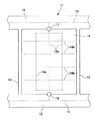
図1は、本発明を適用して管埋設溝を形成した水田の一例を示す概略平面図である。水田11の内部は、農道12及び畦畔13によって複数の耕作区14に区画されており、各農道12には、給水路15と排水路16とがそれぞれ設けられている。さらに、各耕作区14の側縁には、前記給水路15に接続した給水装置17と、排水路16に接続した水位調節装置18とがそれぞれ設置されている。
FIG. 1 is a schematic plan view showing an example of a paddy field in which a pipe embedding groove is formed by applying the present invention. The interior of the
そして、耕作区14の地下には、有孔管からなる暗渠管19a,19bが縦横複数列に埋設されており、主暗渠管19aの上流側が前記給水装置17に接続し、下流側が前記水位調節装置18に接続している。耕作区14は、例えば、長辺が100〜200m、短辺が30〜100m程度の長方形状に区分されているため、主暗渠管19aの最大長さは約200mに達することになる。また、給水装置17から水位調節装置18の方向に向かう主暗渠管19aとこれに直交する副暗渠管19bとは、その交差部で継手等によって接続されている。
Under the cultivated
なお、暗渠管19a,19bの設置数は、耕作区の面積等の状況に応じて設定されるものであり、給水路15や排水路16の設置状態を含めて、図1の状態に限定されるものではない。
The number of
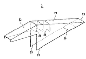
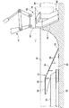
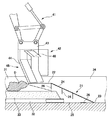
図2は距離の長い管埋設溝を複数回に分割して形成するときに使用する本発明の連続溝形成用治具の一形態例を示す斜視図である。また、図3乃至図6は連続溝形成用治具の使用例を示すもので、図3は先に形成した管埋設溝への連続溝形成用治具の設置状態を示す断面正面図、図4は同じく断面側面図である。また、図5は新たな管埋設溝の終端部分を形成している状態を示す断面正面図、図6は新たな管埋設溝を形成し終えた状態を示す断面正面図である。 FIG. 2 is a perspective view showing an embodiment of a continuous groove forming jig of the present invention used when a long-distance pipe-embedded groove is divided and formed a plurality of times. 3 to 6 show examples of using the continuous groove forming jig, and FIG. 3 is a cross-sectional front view showing the installation state of the continuous groove forming jig in the previously formed tube burying groove. 4 is a sectional side view of the same. FIG. 5 is a sectional front view showing a state in which a terminal portion of a new pipe burying groove is formed, and FIG. 6 is a sectional front view showing a state in which a new pipe burying groove has been formed.
まず、図2に示すように、連続溝形成用治具21は、鋼板等を屈曲させたり、溶接したりして形成されるものであって、管覆い部22と接地部23とを長手方向の両端に有するとともに、形成する管埋設溝の溝幅に対応した幅寸法を有する傾斜板24と、この傾斜板24を支持する一対の脚片25,25とにより形成されており、傾斜板24及び脚片25の内部側には、複数の補強板26が設けられている。
First, as shown in FIG. 2, the continuous
この連続溝形成用治具21は、図3及び図4に示すように、先に形成した管埋設溝31の端部に挿入して使用される。管埋設溝31には、溝形成後に所定位置まで暗渠管32が敷設され、その上部に籾殻等の疎水材33が所定位置まで充填されている。連続溝形成用治具21は、前記管覆い部22及び傾斜板24の一部で暗渠管32の端部上方を覆うとともに、接地部23が管埋設溝31の端部底面に接地するようにして管埋設溝31の内部に挿入される。このとき、脚片25は、その外面が管埋設溝31の溝側壁に沿うように挿入され、脚片25の下端縁は、溝内に敷設された暗渠管32を避けるようにして溝底面に接地した状態となる。
As shown in FIGS. 3 and 4, the continuous
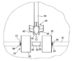
このように、先に形成した管埋設溝31の端部に連続溝形成用治具21を挿入配置した状態で、管埋設溝31の反対方向から新たな管埋設溝34の掘削を行う。本形態例では、作業機のアーム41に溝形成具42を装着し、アーム41を操作して溝形成具42を先に形成した管埋設溝31に向けて水平方向に移動させることにより、新たな管埋設溝34を形成するようにしている。
In this manner, a new
この溝形成具42は、作業機のアーム41に装着される作業機装着部43の下方に、溝形成方向前方側が先鋭化するとともに溝底部側が後退したラッセル部44を有する溝形成部45を設けたものであって、溝形成部45は、管埋設溝34の溝幅に対応した幅寸法を有しており、溝形成部45を地中に挿入してラッセル部44方向に移動させることにより、溝形成部45の挿入深さに対応した深さで、溝形成部45の幅寸法に対応した溝幅の管埋設溝を形成することができる。なお、本例に示す溝形成具42は、溝形成部45の上部両側に掘り上げられた土砂が形成後の管埋設溝内に落下することを防止するための排土板46が設けられている。
The
新たな管埋設溝34の形成が進み、溝形成具42が先に形成した管埋設溝31の終端部分に到達したら、図5に示すように、ラッセル部44の下端が傾斜板24の上方を通過するようにアーム41を操作する。これにより、溝形成具42の先端部分に存在する土砂Dは、溝形成具42の移動に伴って傾斜板24の上方を通り、図6に示すように、先に形成した管埋設溝31に充填された疎水材33の上に落下することになる。
When the formation of the new
このようにして新たな管埋設溝34を形成した後、連続溝形成用治具21を溝内から取り出すことにより、先に形成した管埋設溝31と新たな管埋設溝34とが直線的に連続した状態となる。また、暗渠管32は、管覆い部22及び傾斜板24で覆われているので、管内に土砂が侵入することもない。但し、必要に応じて暗渠管32の端部開口をキャップ等で塞いでおいてもよい。さらに、連続溝形成用治具21を接地部側から持ち上げるようにして溝内から取り出すことにより、傾斜板24上に残った土砂も疎水材33の上に落下させることができる。
After forming the new
管埋設溝31,34が連続した状態になった後、暗渠管32の端部に新たな暗渠管を管埋設溝34方向に接続し、その上部に疎水材を充填した後、疎水材の上部を土砂で埋め戻すことにより、暗渠管の敷設工事が終了する。
After the
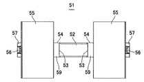
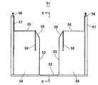
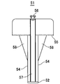
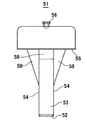
図7乃至図10は、先に形成した管埋設溝に対して直交する方向に新たな管埋設溝を形成する際に使用する交差溝形成用治具の一形態例を示すものであって、図7は平面図、図8は正面図、図9は側面図、図10は図8のX−X断面図である。また、図11乃至図14は、交差溝形成用治具の使用例を示すもので、図11は先に形成した管埋設溝への交差溝形成用治具の設置状態を示す平面図、図12は同じく断面正面図、図13は新たな管埋設溝を形成している状態を示す平面図、図14は同じく断面正面図である。 FIGS. 7 to 10 show an example of a cross groove forming jig used when forming a new pipe burying groove in a direction orthogonal to the previously formed pipe burying groove. 7 is a plan view, FIG. 8 is a front view, FIG. 9 is a side view, and FIG. 10 is a sectional view taken along line XX in FIG. FIGS. 11 to 14 show examples of using the cross groove forming jig, and FIG. 11 is a plan view showing the installation state of the cross groove forming jig in the previously formed tube burying groove. 12 is a cross-sectional front view, FIG. 13 is a plan view showing a state where a new pipe burying groove is formed, and FIG. 14 is a cross-sectional front view.
まず、図7乃至図10に示すように、交差溝形成用治具51は、先に形成した管埋設溝の溝幅に対応した幅寸法を有し、先に形成した管埋設溝の底面上に設置される底板52と、該底板52の中央部から新たに形成する管埋設溝の溝幅よりも大きな間隔で向き合うようにしてそれぞれ鉛直方向に立ち上がり、先に形成した管埋設溝を塞ぐようにして挿入される一対の側板53,53と、底板52の長辺からそれぞれ鉛直方向に立ち上がって先に形成した管埋設溝の側壁に沿うように挿入される一対の壁板54,54と、該側板53及び壁板54の上端部から新たに形成する管埋設溝の溝幅よりも大きな間隔を空けて水平方向にそれぞれ延出した一対の天板55,55と、底板52の両端から天板55の外端を通って鉛直方向に立ち上がるとともに上端に吊下げ部56が設けられた枠部材57と、壁板54の外面から天板55の下面を支持するように設けられた補強板58とを有しており、側板53の上端部には、上方が開いた傾斜面59が設けられている。
First, as shown in FIGS. 7 to 10, the intersecting
このように形成された交差溝形成用治具51は、図11及び図12に示すように、先に形成した管埋設溝61の中間部所定位置、すなわち、新たに形成する管埋設溝の交差位置に挿入された状態で使用される。このとき、底板52は底面上に、側板53,53は管埋設溝61を横切るように、壁板54,54は管埋設溝61の側壁に沿うように、天板55は新たに形成する管埋設溝の部分を除いて管埋設溝61の開口を塞ぐように、補強板58は先に形成した管埋設溝61の側壁に食い込むように、それぞれ配置された状態となる。
As shown in FIGS. 11 and 12, the cross
このように、先に形成した管埋設溝61に交差溝形成用治具51を挿入した状態で、図13及び図14に示すように、前述の溝形成具42を使用し、先に形成した管埋設溝61に直交する方向の新たな管埋設溝62を形成する。新たな管埋設溝62が先に形成した管埋設溝61と交わる位置では、溝形成具42のラッセル部44によって押し拡げられる土砂は、側板53,53によって先に形成した管埋設溝61内に侵入することがなく、また、上方に堀り上げられた土砂Dは、天板55によって先に形成した管埋設溝61内に落下することが防止される。
In this manner, with the cross
新たな管埋設溝62が先に形成した管埋設溝61を通過した後、吊下げ部56を利用してバックホー等で交差溝形成用治具51を溝内から取り出すことにより、先に形成した管埋設溝61内に土砂を侵入させることなく、新たな管埋設溝62を直交させた状態で形成することができる。また、一対の側板53,53の間隔を新たに形成する管埋設溝62の溝幅よりも大きな間隔としておくことにより、新たな管埋設溝62が先に形成した管埋設溝61に対して傾斜していたり、形成位置が多少ずれていたりしても、新たな管埋設溝62を確実に形成することができる。また、側板53,53間に残る土砂は、交差溝形成用治具51を溝内から取り出すときに底板52によって溝外に排出することができる。
After the new
上述のように、連続溝形成用治具21や交差溝形成用治具51を使用することにより、図1に示したような暗渠管19a,19bを耕作区14内に容易にかつ確実に敷設することができる。なお、溝形成具42は、土質等の条件に応じて適当な形状のものを使用することが可能である。
As described above, by using the continuous
11…水田、12…農道、13…畦畔、14…耕作区、15…給水路、16…排水路、17…給水装置、18…水位調節装置、19a,19b…暗渠管、21…連続溝形成用治具、22…管覆い部、23…接地部、24…傾斜板、25…脚片、26…補強板、31…先に形成した管埋設溝、32…暗渠管、33…疎水材、34…、41…アーム、42…溝形成具、43…作業機装着部、44…ラッセル部、45…溝形成部、46…排土板、51…交差溝形成用治具、52…底板、53…側板、54…壁板、55…天板、56…吊下げ部、57…枠部材、58…補強板、59…傾斜面、61…先に形成した管埋設溝、62…新たな管埋設溝
DESCRIPTION OF
Claims (3)
Priority Applications (1)
| Application Number | Priority Date | Filing Date | Title |
|---|---|---|---|
| JP2004111037A JP2005290924A (en) | 2004-04-05 | 2004-04-05 | Method for forming tube burying groove, jig for forming continuous groove and jig for forming cross groove |
Applications Claiming Priority (1)
| Application Number | Priority Date | Filing Date | Title |
|---|---|---|---|
| JP2004111037A JP2005290924A (en) | 2004-04-05 | 2004-04-05 | Method for forming tube burying groove, jig for forming continuous groove and jig for forming cross groove |
Publications (1)
| Publication Number | Publication Date |
|---|---|
| JP2005290924A true JP2005290924A (en) | 2005-10-20 |
Family
ID=35324164
Family Applications (1)
| Application Number | Title | Priority Date | Filing Date |
|---|---|---|---|
| JP2004111037A Pending JP2005290924A (en) | 2004-04-05 | 2004-04-05 | Method for forming tube burying groove, jig for forming continuous groove and jig for forming cross groove |
Country Status (1)
| Country | Link |
|---|---|
| JP (1) | JP2005290924A (en) |
Cited By (2)
| Publication number | Priority date | Publication date | Assignee | Title |
|---|---|---|---|---|
| CN102900059A (en) * | 2012-11-06 | 2013-01-30 | 河海大学 | Combined draining and saline controlling system for saline and alkaline land |
| CN103999739A (en) * | 2014-06-05 | 2014-08-27 | 北京师范大学 | North coastal region saline soil irrigation method and system in winter |
-
2004
- 2004-04-05 JP JP2004111037A patent/JP2005290924A/en active Pending
Cited By (4)
| Publication number | Priority date | Publication date | Assignee | Title |
|---|---|---|---|---|
| CN102900059A (en) * | 2012-11-06 | 2013-01-30 | 河海大学 | Combined draining and saline controlling system for saline and alkaline land |
| CN102900059B (en) * | 2012-11-06 | 2015-07-29 | 河海大学 | The compound drainage control salt system in a kind of salt-soda soil |
| CN103999739A (en) * | 2014-06-05 | 2014-08-27 | 北京师范大学 | North coastal region saline soil irrigation method and system in winter |
| CN103999739B (en) * | 2014-06-05 | 2016-08-10 | 北京师范大学 | Winter irrigation method and system for saline-alkali land in northern coastal areas |
Similar Documents
| Publication | Publication Date | Title |
|---|---|---|
| CN116397475B (en) | In-situ reconstruction and expansion structure of embankment and construction method | |
| CN106087953B (en) | A kind of drainage and construction method for preventing and treating mountain area large size spoil ground mud-rock flow | |
| KR100491410B1 (en) | Drainage structure of an incline area | |
| KR20140096731A (en) | Underground water drainage system of excavated ground and pipeline construction method using the same | |
| CN110952574A (en) | Method for treating landslide deformation body | |
| CN212153420U (en) | Flexible protection system for treating side slope seepage | |
| JP2005290924A (en) | Method for forming tube burying groove, jig for forming continuous groove and jig for forming cross groove | |
| KR20200017132A (en) | Loop steel pipe for preventing ground settlement and tunnel construction method using the same | |
| CN112982459A (en) | Large-area drainage construction method for strongly weathered rock substrate rich in low-pressure-bearing fracture water | |
| CN220394422U (en) | River course shore protection structure and river course protective structure | |
| CN112922670A (en) | Visual and maintainable type anti-clogging drainage system for highway tunnel | |
| JP3663541B2 (en) | Impermeable mountain retaining wall with groundwater flow conservation function and its groundwater flow conservation method | |
| CN111962480B (en) | Water-saving irrigation construction method for high-standard farmland | |
| CN109779682B (en) | Water-rich section highway tunnel escape canal structure system | |
| CN209339104U (en) | The perpendicular rib crib dam of elasticity | |
| CN220166553U (en) | Roadbed structure of mountain area half-digging half-filling | |
| JP2003253611A (en) | Boundary block | |
| JP3700121B2 (en) | Water blocking wall under culvert and its construction method | |
| JP4442724B2 (en) | Groove forming device | |
| KR20150108342A (en) | Underground water drainage system of excavated ground and pipeline construction method using the same | |
| CN220013546U (en) | Concrete lattice slope protection for downstream dam slope of earth-rock dam | |
| JP7072837B2 (en) | Material-free culvert forming method and work machine for material-free culvert forming | |
| JP3241850U (en) | Paddy field drainage preparation structure | |
| JP7566235B1 (en) | Ground improvement methods | |
| CN119777457B (en) | A drainage system and construction method for a sloping spoil disposal site |