JP2005290897A - Panel joint structure - Google Patents
Panel joint structure Download PDFInfo
- Publication number
- JP2005290897A JP2005290897A JP2004109644A JP2004109644A JP2005290897A JP 2005290897 A JP2005290897 A JP 2005290897A JP 2004109644 A JP2004109644 A JP 2004109644A JP 2004109644 A JP2004109644 A JP 2004109644A JP 2005290897 A JP2005290897 A JP 2005290897A
- Authority
- JP
- Japan
- Prior art keywords
- panel
- packing
- joint
- cross
- joint structure
- Prior art date
- Legal status (The legal status is an assumption and is not a legal conclusion. Google has not performed a legal analysis and makes no representation as to the accuracy of the status listed.)
- Withdrawn
Links
Images
Landscapes
- Building Environments (AREA)
Abstract
【課題】 1種類のパッキンによってパネル間の目地部をシールすることができ、また、パネルのコーナー部におけるパネル内への雨水進入防止に付いての水密性の向上を図れるようにしたパネルの目地構造を提供すること。
【解決手段】 接合される複数のパネルPの側面17間に形成される目地部16にパッキン2を配設し、パッキン2に設けられた一対の突起部21を、それぞれパネルPの目地部16に形成された溝15内に嵌合すると共に、パネルPの側面17にフィン23を接触させた状態でシールする。この際、両突起部21とフィン23を連結する伸縮性及び可撓性を有する間隔調整部24が、パネルPの目地部16の隙間1の間隔や段差に対応して変形するので、シール性の向上が図れる。
【選択図】 図2PROBLEM TO BE SOLVED: To seal a joint between panels by one kind of packing, and to improve the water tightness for preventing rainwater from entering into the panel at a corner of the panel. Providing structure.
A packing 2 is disposed on a joint 16 formed between side surfaces 17 of a plurality of panels P to be joined, and a pair of protrusions 21 provided on the packing 2 are respectively connected to the joint 16 of the panel P. Are fitted in the grooves 15 formed in the above, and the fins 23 are brought into contact with the side surfaces 17 of the panel P for sealing. At this time, the space adjusting portion 24 having elasticity and flexibility connecting both the projecting portions 21 and the fins 23 is deformed corresponding to the space 1 and the step of the joint portion 16 of the panel P. Can be improved.
[Selection] Figure 2
Description
この発明は、例えば建築物の屋根、バス停等のシェルタ、渡り廊下の屋根等を構成するパネルの目地構造に関するものである。 The present invention relates to a joint structure of a panel constituting, for example, a roof of a building, a shelter such as a bus stop, a roof of a passageway, or the like.
従来、建築物の屋根、バス停等のシェルタ、渡り廊下の屋根等を構成する軽量かつ耐食性に優れたパネルの1つとして、一対のアルミニウム製表面板と、両表面板間に介在されるアルミニウム製のハニカムコア材と、両表面板の辺部間に配置されるアルミニウム製の枠材とをろう付け一体化したろう付けハニカムパネルが使用されている。 Conventionally, as one of the lightweight and corrosion-resistant panels constituting a roof of a building, a shelter such as a bus stop, a roof of a walkway, etc., a pair of aluminum surface plates and an aluminum product interposed between both surface plates A brazed honeycomb panel is used in which a honeycomb core material and an aluminum frame member disposed between the side portions of both surface plates are brazed and integrated.
また、一般に、建築物の屋根を構成するパネル間の目地部にはパネル間の水密ないし気密を保持するためパッキンを配設して、パネル間の目地部を水密ないし気密のために施工することが知られている。 Also, in general, the joints between the panels constituting the roof of the building are provided with packings to maintain the watertightness or airtightness between the panels, and the joints between the panels are constructed for watertightness or airtightness. It has been known.
このため、従来では、各パネルの接合部に取り付けられる目地ガスケットと、パネルの接合部に取り付けられると共に、パネル同士の接合時に接触し、かつ、目地ガスケットの内外面のいずれか一方に接触してクロス目地部をシールする弾性定形シーリング材とからなる目地構造が知られている(例えば、特許文献1参照)。 For this reason, conventionally, it is attached to the joint gasket of each panel and the joint of the panel, is in contact with the panels, and is in contact with either the inner or outer surface of the joint gasket. A joint structure comprising an elastic fixed sealing material that seals a cross joint is known (see, for example, Patent Document 1).
また、パネルに相当する各カーテンウォールユニットの周囲に取り付けられた目地パッキンと、接合時に密着される目地パッキン同士の隙間に挿入される挿入部分と、目地の間に挟み込まれる弾性変形可能なベース部とからなるクロスパッキンを用いた目地構造も知られている(例えば特許文献2参照)。
しかしながら、従来の特開2000−11026及び実開平5−21010号のいずれの技術においても、目地ガスケットと弾性定形シーリング材、あるいは、目地パッキンとこれとは別体のクロスパッキンの2部材でシールする構造であるため、構成部材が多くなると共に、複数のパッキンを気水密に密着させるには施工に熟練を要し、目地部のシールが十分でないという問題があった。特に、パネル同士の目地部の隙間寸法の誤差やパネルの厚さ方向の段差が生じた場合、目地部のシールが不十分となる虞がある。 However, in any of the techniques disclosed in Japanese Patent Laid-Open No. 2000-11026 and Japanese Utility Model Laid-Open No. 5-21010, sealing is performed with two members, a joint gasket and an elastic fixed sealing material, or a joint packing and a separate cross packing. Due to the structure, there are problems that the number of constituent members increases and that a plurality of packings are brought into close contact with each other in a gas-water tight manner. In particular, when an error in the gap size between the joint portions of the panels or a step in the thickness direction of the panel occurs, there is a possibility that the joint portion is not sufficiently sealed.
また、ろう付けハニカムパネルを屋根に使用した場合には、パネルのコーナー部において、枠材の当接部に僅かな隙間が生じていても、この隙間からパネル内に雨水等が侵入する虞がある。 In addition, when a brazed honeycomb panel is used for the roof, there is a risk that rainwater or the like may enter the panel from this gap even if a slight gap is generated in the contact portion of the frame material at the corner of the panel. is there.
この発明は、上記事情に鑑みてなされたもので、1種類のパッキンによってパネル間の目地部をシールすることができ、また、パネルのコーナー部およびクロス目地部における気水密性の向上を図れるようにしたパネルの目地構造を提供することを課題とする。 The present invention has been made in view of the above circumstances, and can seal the joints between the panels with one type of packing, and can improve the air-tightness at the corners and the cross joints of the panels. It is an object of the present invention to provide a joint structure for a panel.
上記課題を解決するために、請求項1記載のパネルの目地構造は、接合される複数のパネルの側面間に形成される目地部にパッキンを配設して、パネル間の隙間をシールするパネルの目地構造であって、 上記パネルの側面部にパッキン取付用の溝を形成し、 上記パッキンは、一対の基部と、基部に形成され隣接するパネルの上記溝内にそれぞれ嵌合される一対の突起部と、基部に形成され上記パネルの側面に接触する一対のフィンと、上記一対の基部同士を連結する伸縮性及び可撓性を有する間隔調整部とより形成してなる、ことを特徴とする。この場合、パネルの側部に形成されるパッキン取付用の溝と、パッキンに設けられる突起部は、互いに嵌合可能な形状であれば任意の形状であっても差し支えないが、好ましくは、上記パネルの側面に形成される溝を、目地部の外方に向って開口する狭隘開口状に形成し、上記パッキンの突起部に、上記溝の狭隘開口部を嵌挿した後に狭隘開口部に係合する弾性変形可能な係止片を形成する方がよい(請求項2)。
In order to solve the above-mentioned problem, the joint structure of the panel according to
請求項3記載のパネルの目地構造は、請求項1記載のパネルの目地構造における3ないし4枚のパネルが隣接するパネルのクロス目地部の隙間を塞ぎシールする目地構造であって、 上記パッキンは2枚のパネル間の直状目地部が形成される部分の直状パッキン部とクロス状目地部が形成される部分に配設されるクロスパッキン部とより形成され、 上記各パネルの2辺の側面に形成されるパッキン取付用の溝は、コーナー部で連続し、 上記クロスパッキン部には、直状パッキンに連続して、基部と各パネルの上記溝に嵌合される突起部とパネルの側面に接触するフィンが形成されると共に、各基部同士を連結する伸縮性及び可撓性を有する間隔調整部により連結されてクロス目地部の隙間を塞ぎ、 上記各パネルのコーナー部近傍の側面とパッキンのクロス目地部近傍のフィンとの間を接着剤で接着すると共に、その外面を不定形のシーリング材で覆ってなる、ことを特徴とする。 The joint structure of the panel according to claim 3 is a joint structure in which three to four panels in the joint structure of the panel according to claim 1 close and seal a gap between cross joint portions of adjacent panels, A straight packing portion at a portion where the straight joint portion between the two panels is formed and a cross packing portion disposed at a portion where the cross joint portion is formed; The groove for packing attachment formed on the side surface is continuous at the corner portion, the cross packing portion is continuous with the straight packing, the base portion, the projection portion fitted into the groove of each panel, and the panel Fins that are in contact with the side surfaces are formed, and are connected by a space adjusting portion having elasticity and flexibility to connect the bases to each other, thereby closing the gaps in the cross joints. While bonding with an adhesive between the cross joint portion near the fin Kkin, the outer surface becomes covered with amorphous sealant, characterized in that.
請求項3記載の発明において、上記各パネルのコーナー部近傍の側面とパッキンのクロス目地部近傍のフィンとの間を接着剤で接着された部分を覆うシーリング材のバックアップをする起立壁を、パネル側面と平行にパッキンの基部のクロス目地部近傍に設け、 この起立壁とパネルの側面との間にシーリング材の溜まり部を形成し、このシーリング材の溜まり部に不定形シーリング材を充填してもよい(請求項4)。この場合、上記起立壁の高さを、パネルの表面近傍高さとする方が好ましい(請求項5)。また、上記起立壁の端部に、パネルの側面に接触可能な端部壁を設け、これら起立壁及び端部壁とパネルの側面とによって、上記シーリング材溜まり部を包囲し、このシーリング材溜まり部にシーリング材を充填する方が好ましい(請求項6)。 In the invention according to claim 3, an upstanding wall that backs up a sealing material that covers a portion where the side surface in the vicinity of the corner portion of each panel and the fin in the vicinity of the cross joint portion of the packing are bonded with an adhesive is provided. Provided in the vicinity of the cross joint at the base of the packing in parallel with the side, and a sealant reservoir is formed between the standing wall and the side of the panel, and the sealant reservoir is filled with an amorphous sealant. (Claim 4). In this case, it is preferable that the height of the standing wall is the height near the surface of the panel. Further, an end wall that can come into contact with the side surface of the panel is provided at an end portion of the standing wall, and the sealing material reservoir is surrounded by the standing wall, the end wall, and the side surface of the panel. It is preferable to fill the part with a sealing material (claim 6).
この発明によれば、上記のように構成されているので、以下のような効果が得られる。 According to this invention, since it is configured as described above, the following effects can be obtained.
(1)請求項1記載の発明によれば、パッキンに設けられた一対の突起部を、それぞれパネルの側面に形成されたパッキン取付用の溝内に嵌合すると共に、パネルの側面に気水密用のフィンを接触させた状態でパネル間の目地部をシールすることができる。この際、伸縮性及び可撓性を有する間隔調整部が、パネルの目地部の隙間の間隔や段差に対応して変形するので、パネル間の目地間隔の誤差や段差(内外方向の位置)が生じても間隔調整部にて誤差を吸収するので、気水密用のフィンとパネル側面間の密着性は維持でき、シール性の向上が図れる。したがって、複数のパッキンを組み合わせることなく1つのパッキンによってパネル間の目地の隙間を容易かつ確実にシールすることができる。この場合、パネルの側面に形成される溝を、目地部の外方に向って開口する狭隘開口状に形成し、パッキンの突起部に、上記溝の狭隘開口部を嵌挿した後に狭隘開口部に係合する弾性変形可能な係止片を形成することにより、パッキンの取付を容易かつ確実にすることができる(請求項2)。 (1) According to the first aspect of the present invention, the pair of protrusions provided on the packing are fitted in the packing mounting grooves formed on the side surfaces of the panel, respectively, and the side surfaces of the panel are airtight. The joint between the panels can be sealed in a state in which the fins are in contact with each other. At this time, since the distance adjusting portion having elasticity and flexibility is deformed in accordance with the gap interval or step of the joint portion of the panel, an error or step (position in the inner and outer directions) of the joint interval between the panels is reduced. Even if it occurs, since the error is absorbed by the gap adjusting section, the adhesion between the air / water tight fin and the side surface of the panel can be maintained, and the sealing performance can be improved. Therefore, the joint gap between the panels can be easily and reliably sealed with one packing without combining a plurality of packings. In this case, the groove formed on the side surface of the panel is formed in a narrow opening shape that opens outwardly of the joint portion, and the narrow opening portion is inserted after the narrow opening portion of the groove is inserted into the protrusion of the packing. By forming an elastically deformable locking piece that engages with the packing, the packing can be easily and reliably attached (Claim 2).
(2)請求項3記載の発明によれば、3ないし4のパネルでクロス目地部が形成される場合において、基部同士を連結する伸縮性及び可撓性を有する間隔調整部によりクロス目地部が塞がれる。また、パネルのクロス目地部近傍では3ないし4のパネルが近接するが施工誤差、パネル自体の寸法誤差による目地寸法誤差や内外方向の位置の誤差を生じやすく、パネル側面とフィン間の密着性能が低下し易い部分であるが、これらパネルの側面と気水密用のフィンとの間を接着剤で接着するので、パネル間の間隔寸法等に誤差が生じ易いクロス目地部近傍でも、上記(1)に加えて更にパネルのコーナー部の目地部すなわちクロス目地部のシール性の向上を図ることができる。また、接着剤を施した部分はシーリング材にて覆われ紫外線等による接着剤の劣化も生じないので水密性が長期に維持できる。 (2) According to the invention described in claim 3, in the case where the cross joint portion is formed by 3 to 4 panels, the cross joint portion is formed by the space adjusting portion having stretchability and flexibility connecting the base portions. It is blocked. In addition, 3 to 4 panels are close to each other in the vicinity of the cross joint of the panel. However, the construction error, the joint dimensional error due to the dimensional error of the panel itself, and the position error in the inside and outside directions are likely to occur, and the adhesion performance between the panel side surface and the fin is Although it is a portion that tends to be lowered, since the side surfaces of these panels and the air-tight fins are bonded with an adhesive, the above-mentioned (1) even in the vicinity of the cross joint where errors in the spacing between the panels are likely to occur. In addition to this, it is possible to further improve the sealing performance of the joint portion of the panel, that is, the cross joint portion. In addition, since the adhesive-coated portion is covered with a sealing material and the adhesive is not deteriorated by ultraviolet rays or the like, water tightness can be maintained for a long time.
(3)請求項4記載の発明によれば、パッキンのクロス目地部近傍のフィン外面にシーリング材をバックアップする起立壁を、パネル側面と平行にパッキンの基部のクロス目地部近傍に設け、この起立壁とパネルの側面との間にシーリング材溜まり部を形成し、このシーリング材溜まり部にシリコンシーラントのような不定形のシーリング材を充填するので、上記(1)に加えて更にパネルのコーナー部の目地部すなわちクロス目地部のシール性の向上及びシール部の劣化防止を図ることができる。また、シーリング材の充填作業を容易かつ確実にすることができる。この場合、起立壁の高さを、パネルの表面近傍高さとすることにより、パネルのコーナーの側面の全域をシーリング材で覆うことができる。 (3) According to the invention described in claim 4, the standing wall for backing up the sealing material is provided on the outer surface of the fin in the vicinity of the cross joint portion of the packing in the vicinity of the cross joint portion of the base portion of the packing in parallel to the side of the panel. A sealing material reservoir is formed between the wall and the side of the panel, and the sealing material reservoir is filled with an irregular sealing material such as a silicone sealant. It is possible to improve the sealability of the joint portion, that is, the cross joint portion and to prevent the seal portion from being deteriorated. In addition, the sealing material can be easily and reliably filled. In this case, by setting the height of the standing wall to the height near the surface of the panel, the entire area of the side surface of the corner of the panel can be covered with the sealing material.
これによりパネルに例えばろう付けハニカムパネルを使用した場合に、パネルのコーナー部での枠材の当接部を留めに接合したような場合(縦横の枠材の45度仕口部)や、この当接部を溶接して角部が溶融して形状が不正となる等によりフィンとパネル側面間に僅かな隙間があったとしても不定形のシーリング材によってシールすることができ、目地より内部への雨水の浸入や、パネルの内部への雨水の浸入を防止できる(請求項5)。 Thus, for example, when a brazed honeycomb panel is used for the panel, when the contact portion of the frame material at the corner portion of the panel is fastened and joined (45 ° joint portion of the vertical and horizontal frame material), Even if there is a slight gap between the fin and the side of the panel, such as when the contact part is welded and the corner melts and the shape becomes incorrect, it can be sealed with an irregular sealing material, from the joint to the inside Intrusion of rainwater and intrusion of rainwater into the panel can be prevented (claim 5).
(4)請求項6記載の発明によれば、起立壁の端部に、パネルの側面に接触可能な端部壁を設け、これら起立壁及び端部壁とパネルの側面とによって、シーリング材溜まり部を包囲し、このシーリング材溜まり部にシーリング材を充填するので、上記(3)に加えて更にシーリング材の充填作業を容易かつ確実にすることができると共に、シール部の美観の向上を図ることができる。 (4) According to the invention described in claim 6, an end wall that can come into contact with the side surface of the panel is provided at the end portion of the standing wall, and the sealing material pool is formed by the standing wall and the end wall and the side surface of the panel. Since the sealing material is surrounded and the sealing material reservoir is filled with the sealing material, in addition to the above (3), the sealing material can be filled more easily and reliably, and the aesthetics of the sealing portion can be improved. be able to.
以下に、この発明に係るパネルの目地構造の最良の実施形態を添付図面に基づいて詳細に説明する。 DETAILED DESCRIPTION OF THE PREFERRED EMBODIMENTS Embodiments of a joint structure for a panel according to the present invention will be described below in detail with reference to the accompanying drawings.
<第1実施形態>
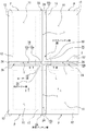
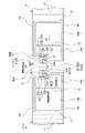
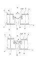
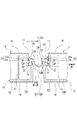
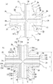
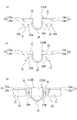
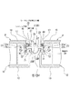
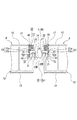
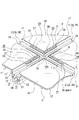
図1は、この発明に係るパネルの目地構造を示す概略平面図、図2は、図1のI−I線に沿う断面図、図3は、パネルの目地部に取り付けられたパッキンの変形状態を示す断面図(a)及び(b)、図4は、図1のII−II線に沿う断面図である。
<First Embodiment>
1 is a schematic plan view showing a joint structure of a panel according to the present invention, FIG. 2 is a cross-sectional view taken along line II of FIG. 1, and FIG. 3 is a deformed state of a packing attached to the joint part of the panel FIGS. 4A and 4B are sectional views taken along line II-II in FIG.
この実施形態においては、複数(この場合4枚)のパネルPのコーナー部18に形成されるクロス目地部16a及び該クロス目地部16aに連なる直状目地部16bにおけるパネルPの側面間に形成される隙間1(以下に目地1という)に1種類のパッキン2を配設して目地1をシールしている(図1参照)。
In this embodiment, it is formed between the side surface of the panel P in the cross
上記パネルPは、図2に示すように、それぞれアルミニウム製の一対の表面板10と、表面板10間に介在されるアルミニウム製のコア材11と、両表面板10の辺部間に介在されるアルミニウム製の枠材12とを一体にろう付けしたろう付けハニカムパネルにて形成されている。
As shown in FIG. 2, the panel P is interposed between a pair of
この場合、コア材11は、例えば、複数のアルミニウム製帯板を千鳥状に接着した後、帯板同士が離れる方向に引張力を加えて作成されるエキスパウンドコア材(ハニカムコア)、あるいは、多数の中空筒状のコア単体を集合させた中空コア材等により形成されている。
In this case, the
また、枠材12は、図2に示すように、仕切壁13によって区画された2つの中空部14a,14bを有し、中空部14aの目地部16側の側面17にパッキン取付用の溝15が形成されている。この場合、溝15は、パネルPのコーナー部で連続すると共に、目地部16の外方(図2において上方)に向かって狭隘開口状の開口部15aを有している。なお、側面17の外方側の部分は、内方側部分より目地部16の幅が広くなっている。
As shown in FIG. 2, the
一方、パッキン2は、図1に示すように、それぞれ例えばクロロプレンゴムのような伸縮性及び可撓性を有する材料にて形成される直状パッキン部2Aが形成される。
On the other hand, as shown in FIG. 1, the
また、クロスパッキン部2Bは直状パッキン部2A間を繋ぐように射出成形により直状パッキン部2Aと一体化するように形成されている。この場合、直状パッキン部2Aは、押出成形にて直状に形成され、クロスパッキン部2Bは、射出成形にてパネルPのコーナー部18に接合する内コーナー部26を有するクロス状に形成されている。なお、本実施態様においては、このクロスパッキン部2Bの大きさは図1、図5(b)に示した長さLを35mmとしたが30mmから55mm程度が適当である。
Moreover, the
また、パッキン2は、図2、図5及び図6に示すように、一対の基部25,25と、基部の内方(図2中下方)に形成され接合されるパネルPの側面17に形成された溝15内に嵌合される一対の突起部21と、基部25に形成されパネルPの側面17に接触可能な可撓性を有する一対の複数(図2では2つの場合を示す)の気水密用のフィン23と、基部25同士を連結する伸縮性及び可撓性を有する断面略U字状の間隔調整部24とで主に形成されている。
Further, as shown in FIGS. 2, 5 and 6, the
この場合、直状パッキン部2Aの突起部21は、図2及び図6(a)に示すように、溝15の狭隘開口部15aに嵌挿された後に狭隘開口部15aに係合する弾性変形可能な矢尻状の係止片22Aを有している。また、クロスパッキン部2Bの突起部21は、図4及び図6(b)に示すように、溝15の狭隘開口部15aに嵌挿された後に狭隘開口部15aに係合する弾性変形可能な片矢尻状の係止片22Bを有している。
In this case, as shown in FIG. 2 and FIG. 6A, the
一方、上記フィン23は、図2及び図6に示すように、上記基部25の側方から側方(パネルの側面側)に向かって突出し、先端がパネルPの側面17に湾曲状に圧接する第1フィン23aと、突起部21の基端部側面に位置し、第1フィン23aとの間に隙間を設けて突出し、第1フィン23aと同様に、先端がパネルPの側面17に湾曲状に圧接する第2フィン23bとによって形成されている。この場合、第1フィン23aは、第2フィン23bより若干長く突出している。なお、直状パッキン部2A及びクロスパッキン部2Bのフィン23は同一断面形状で一体化され連続している。
On the other hand, as shown in FIGS. 2 and 6, the
このようにフィン23を形成することによって、パッキン2をパネルPに取り付ける際、可撓性を有する第1フィン23a及び第2フィン23bの先端がパネルPの側面17に可撓性を有して湾曲した状態で接触することで、第1フィン23a及び第2フィン23bをパネルPの側面17に密着することができるので、パネルPの外方からの空気や水等の浸入を防ぐことができる。
By forming the
一方、上記間隔調整部24は、図2及び図6に示すように、基部25同士を連結するようにフィン23と反対位置に設けられ、パネルPの目地部16を覆っている。また、間隔調整部24は、伸縮性及び可撓性を有すると共に外方(上方)に開口を有する断面略U字状に形成されている。
On the other hand, as shown in FIG. 2 and FIG. 6, the
この場合、直状パッキン部2A及びクロスパッキン部2Bの間隔調整部24は同一断面形状で一体化され連続している。なお、クロスパッキン部2Bの間隔調整部24のクロス部は、図5及び図6(c)に示すように、各間隔調整部24のU字状部分が十字状に連続するように連結されて、クロス目地部の隙間を塞いでいる。
In this case, the
このように間隔調整部24を形成することによって、接合されるパネルP間の目地1を覆うことができるので、パネルPの目地部16の美観の向上を図ることができる。また、間隔調整部24は、図3(a)に示すように、パネルPの目地部16の目地1の間隔Wが広い場合や狭い場合に、又は、図3(b)に示すように、パネルPの目地部16に段差Hが生じている場合に、これら間隔Wや段差Hの変化に追従して変形することができるので、目地1のシール性の維持を図ることができる。例えば、パネルPの目地部16の標準目地幅Wを20mmとした場合、目地幅Wの変動±5mm、段差Hの変動+5mmに対応することができる。
By forming the
また、上記パッキン2は、図4に示すように、パネルPのクロス目地部16aのクロスパッキン部2Bにおいて、フィン23とパネルPの側面17との間、さらにパッキン2の突起21と溝15のパネル側部分に、接着剤30を介在してパネルPとパッキン2とを接着している。
Further, as shown in FIG. 4, the
また、クロス目地部16a近傍は、3枚ないし4枚のパネルが接近しパネル間の目地間隔や内外方向の位置の誤差が施工時はもとより施工後の経時変化で生じやすく、また、パネル自体の寸法誤差も生じやすい箇所である。この誤差を前記パッキンの間隔調整部24にて、対応させることは困難なことである。
Also, in the vicinity of the cross
しかしながら、このようにクロスパッキン部2Bのフィン23ないし突起21とパネルPの側面17との間に接着剤30を施すことにより、パッキンとパネル側面間は完全な密封構造となりパッキンの間隔調整部24による寸法誤差への対応限界を大きく向上させることができ、水密性の向上を果たせる。
However, by applying the adhesive 30 between the
なお、この接着剤30を施す箇所をクロスパッキン部2Bより大きくして例えば直状パッキン部2Aの一部にも施してもよい(例えば上述の寸法Lにして100ないし150mm)。また、フィン23とパネルPが接着されていればよいので、突起21にまで必ずしも接着剤を施工さなくともよいのであるが、クロスパッキン部2Bの係止片は片矢尻状としたので、係止強度の補強効果もあり接着剤を施すことが好ましい。
In addition, you may make the location which applies this
この接着を施した箇所のフィン23の更に外面にはシーリング材40が施される。これにより紫外線等による接着剤30劣化が防止され耐久性が向上し、パネルPのクロス目地部16aのシール性の向上及び接着剤の劣化防止によるシール性の向上を図ることができる。
A sealing
次に、パネルP間の目地1へのパッキン2の取付方法を説明する。まず、複数(この場合4つ)のパネルP間のクロス目地部16aに、パッキン2のクロスパッキン部2Bを配置すると共に、直状目地部16bに直状パッキン部2Aを配置する。この際、クロス目地部16a近傍のパネル側面17及び溝15の一部に接着剤30を塗布するか、あるいは、クロスパッキン部2Bのフィン23に接着剤30を塗布しておく。この状態で、クロスパッキン部2Bの突起部21の基端部を押圧し、突起部21をパネルPの目地部16に形成された溝15内に嵌挿し、係止片22Bを狭隘開口部15aに係合させると共に、クロスパッキン部2Bのフィン23をパネルPの側面17に接触させると共に、接着させる。
Next, a method for attaching the
次いで、これに連続する直状パッキン部2Aの突起部21の基端部を押圧して直状パッキン部2Aの突起部21を直状目地部16bのパネルPの側面17の溝15内に嵌挿し、係止片22Aを狭隘開口部15aに係合させると共に、直状パッキン部2Aのフィン23をパネルPの側面17に接触させる。その後、クロス目地部16aにおけるパネルPとパッキン2の接着部の外面にシーリング材40を施すことで、パッキン2を目地1に気水密に装着する。
Next, the base end portion of the projecting
したがって、1種類(1つの)のパッキン2によってパネルP間の目地1を容易かつ確実にシールすることができる。この場合、パネルPの側面17に形成される溝15に狭隘開口部15aを形成し、パッキン2の突起部21に、溝15の狭隘開口部15aを嵌挿した後に狭隘開口部15aに係合する弾性変形可能な係止片22A,22Bを形成することにより、パッキン2の取付を容易かつ確実にすることができる。また、クロス目地部16aのパネルのコーナー部とその近傍の側面17とクロスパッキン部2Bのフィン23との間に、接着剤30を介在してパネルPとパッキン2とを接着し、パネルPとパッキン2の接着部の外面にシリコンシーラントのような不定形のシーリング材40を塗布するので、目地間隔の誤差等を生じ易いクロス目地部16aのシール性の向上及びシール部の劣化防止を図ることができる。
Therefore, the joint 1 between the panels P can be easily and reliably sealed by one type (one) of the
なお、射出成形により形成されるクロスパッキン部2Bの突起部21の矢尻22Bはパネル側面17側の矢尻が形成されていないが、これは射出成形に際して成形困難のために省略したが、この部分にも接着剤30が施されるので、パッキンが外れる等の取付上の問題は生じない。
The
<第2実施形態>
第2実施形態は、上記各パネルPのコーナー部近傍の側面17とパッキンのクロス目地部近傍のフィン23との間の接着剤30で接着された部分の外面を覆うシーリング材40のバックアップをする起立壁27を、パネル側面17と平行にパッキンの基部25に設け、この起立壁とパネルの側面との間にシーリング材の溜まり部を形成することによりシーリング材の充填作業と容易にするものである。
Second Embodiment
2nd Embodiment backs up the sealing
なお、この接着剤30を施す箇所をクロスパッキン部2Bより大きくして例えば直状パッキン部2Aの一部にも施してもよい(例えば上述の寸法Lにして100ないし150mm)。
In addition, you may make the location which applies this
また、本実施の形態は、更にはパネルコーナー部での水密性の向上をも図れるようにした場合の形態である。すなわち、図7及び図9に示すように、パネルPのクロスパッキン部2Bのフィン23とパネルPのコーナー部18における側面17との間に、接着剤30を介在してパネルPとパッキン2(クロスパッキン部2B)のフィン23とを接着し、クロス目地部16a付近の外面に設けられた充填されるシーリング材40をバックアップする起立壁27とパネルPの側面17との間に、シーリング材40を充填する構造にした場合である。
Further, the present embodiment is a form in which the water tightness at the panel corner can be improved. That is, as shown in FIGS. 7 and 9, the panel P and the packing 2 (with the adhesive 30 interposed between the
この場合、上記起立壁27は、図5(a)、図7及び図9に示すように、クロスパッキン部2Bの基部25の外面に、クロスパッキン部2Bの内コーナー部26に沿って可撓性を有する長さLc(本態様にあっては接着部の長さ5〜30mm、本例では+10mm)にわたり基部25に形成されている。また、起立壁27の端部には、パネルPの側面17に接触可能な可撓性を有する端部壁28が形成されている。この場合、起立壁27及び端部壁28は、例えば接着等によりクロスパッキン部2B及び直状パッキン2Aに取り付けられるか、あるいは、クロスパッキン部2Bの射出成形に際して一体に形成されている。このように形成された起立壁27及び端部壁28とパネルPの側面17とによって、シーリング材溜まり部29が形成され、このシーリング材溜まり部29内にシリコンシーラントのような不定形シーリング材40を充填することができる。
In this case, the
このように起立壁27及び端部壁28とパネルPの側面17とによって形成されたシーリング材溜まり部29内に、シーリング材40を充填することによって、シーリング材40の充填作業に熟練を要することなく、容易かつ確実にすることができる。また、シーリング材溜まり部29内にシーリング材40を充填することができるので、シール部の美観の向上を図ることができる。
In this way, the sealing
また、これにより、クロス目地16a近傍にて、フィン23とパネル側面17間の接着部分の接着剤30の劣化が確実に防げる。
This also reliably prevents deterioration of the adhesive 30 at the bonding portion between the
更に、パネルのコーナー部での枠材12の当接部を溶接して角部が溶融して形状が不正となる等によりフィン23とパネル側面17間に僅かな隙間があったとしても不定形のシーリング材によってシールすることができ、当接部に仮に不良が生じたとしてもその部分より、パネルの内部への雨水の浸入を防止できる。
Furthermore, even if there is a slight gap between the
なお、この場合、起立壁27及び端部壁28の高さを、図8に示すように、パネルPの表面近傍高さに形成する方が好ましく、パネルの表面部までシーリング材40で覆うことが更に好ましい。その理由は、起立壁27及び端部壁28をパネルPの表面近傍高さに形成することにより、クロス目地部16a付近のパネルPの側面17の全域をシーリング材40で覆うことができるので、パネルPに例えばろう付けハニカムパネルPを使用した場合に、パネルPのコーナー部の枠材12の当接部(縦横の枠材の仕口部)が完全にシーリング材40によってシールされるので、万一仕口部の不良が生じてもパネルP自体への雨水の浸入等の防止を確実の図ることができる。
In this case, it is preferable that the height of the standing
なお、第2実施形態においては、起立壁27の端部に端部壁28を設けてシーリング材溜まり部29を形成する構造について説明したが、必ずしも端部壁28を設ける必要はなく、起立壁27の端部を開放した状態で、起立壁27とパネルPの側面17とによってシーリング材溜まり部29を形成する構造としてもよい(図示せず)。
In the second embodiment, the structure in which the
なお、第2実施形態において、その他の部分は、第1実施形態と同様に形成されるので、同一部分には同一符号を付して説明は省略する。 In the second embodiment, the other parts are formed in the same manner as in the first embodiment, so the same parts are denoted by the same reference numerals and description thereof is omitted.
また、上記第1及び第2実施形態においては、4枚のパネルPの目地部16がクロス状に形成される場合の目地構造について説明したが、この発明における目地構造は、パネルPの枚数は4枚に限らず、例えば3枚のパネルPの目地部をT字状に形成する場合においても適用することができる。この場合、パッキン2は、上記クロスパッキン部2Bに代えて、略T字状のパッキン部に直状パッキン部を連結して形成される(図示せず)。
In the first and second embodiments, the joint structure in the case where the
P パネル
1 目地(隙間)
2 パッキン
2A 直状パッキン部
2B クロスパッキン部
15 溝
15a 狭隘開口部
16 目地部
17 側面
18 コーナー部
21 突起部
22A,22B 係止片
23 フィン
24 間隔調整部
25 基部
26 内コーナー部
27 起立壁
28 端部壁
29 シーリング材溜まり部
30 接着剤
40 シーリング材
2 Packing 2A
Claims (6)
上記パネルの側面にパッキン取付用の溝を形成し、
上記パッキンは、一対の基部と、基部に形成され隣接するパネルの上記溝内にそれぞれ嵌合される一対の突起部と、基部に形成され上記パネルの側面に接触する一対のフィンと、上記一対の基部同士を連結する伸縮性及び可撓性を有する間隔調整部とより形成してなる、ことを特徴とするパネルの目地構造。 A joint structure for a panel that seals a gap between the panels by arranging packing at joints formed between the side surfaces of the plurality of panels to be joined,
Form a packing mounting groove on the side of the panel,
The packing includes a pair of base portions, a pair of protrusions formed in the base portion and fitted into the grooves of adjacent panels, a pair of fins formed in the base portion and in contact with the side surfaces of the panel, and the pair A joint structure for a panel, characterized in that it is formed of a space adjusting portion having elasticity and flexibility for connecting the base portions of each other.
上記パネルの側面に形成される溝を、目地部の外方に向って開口する狭隘開口状に形成し、
上記パッキンの突起部に、上記溝の狭隘開口部を嵌挿した後に狭隘開口部に係合する弾性変形可能な係止片を形成してなる、ことを特徴とするパネルの目地構造。 In the joint structure of the panel according to claim 1,
The groove formed on the side surface of the panel is formed in a narrow opening shape that opens toward the outside of the joint,
A joint structure for a panel, characterized in that an elastically deformable locking piece that engages with the narrow opening after the narrow opening of the groove is inserted into the protrusion of the packing.
上記パッキンは2枚のパネル間の直状目地部が形成される部分の直状パッキン部と、クロス状目地部が形成される部分に配設されるクロスパッキン部とより形成され、
上記各パネルの2辺の側面に形成されるパッキン取付用の溝は、コーナー部で連続し、
上記クロスパッキン部には、直状パッキンに連続して、基部と各パネルの上記溝に嵌合される突起部とパネルの側面に接触するフィンが形成されると共に、各基部同士を連結する伸縮性及び可撓性を有する間隔調整部により連結されてクロス目地部の隙間を塞ぎ、
上記各パネルのコーナー部近傍の側面とパッキンのクロス目地部近傍のフィンとの間を接着剤で接着すると共に、その外面を不定形のシーリング材で覆ってなる、ことを特徴とするパネルの目地構造。 A joint structure in which 3 to 4 panels in the joint structure of the panel according to claim 1 close and seal a gap between cross joint portions of adjacent panels,
The packing is formed of a straight packing portion at a portion where a straight joint portion between two panels is formed, and a cross packing portion disposed at a portion where a cross joint portion is formed,
The packing mounting grooves formed on the two side surfaces of each panel are continuous at the corners,
The cross packing portion is formed with a fin that is in contact with the side surface of the panel, a protrusion portion that fits into the groove of the base portion, and the base portion, and the expansion and contraction that connects the base portions to each other. Connected by a gap adjusting portion having flexibility and flexibility to close the gap of the cross joint portion,
The panel joint characterized by adhering between the side surface near the corner portion of each panel and the fin near the cross joint portion of the packing with an adhesive, and covering the outer surface with an irregular sealing material. Construction.
上記各パネルのコーナー部近傍の側面とパッキンのクロス目地部近傍のフィン間の接着剤で接着された部分の外面を覆うシーリング材のバックアップをする起立壁を、パネル側面と平行にパッキンの基部に設け、この起立壁とパネルの側面との間にシーリング材の溜まり部を形成し、このシーリング材の溜まり部に不定形シーリング材を充填してなる、ことを特徴とするパネルの目地構造。 In the joint structure of the panel according to claim 3,
An upright wall that backs up the sealing material that covers the outer surface of the part bonded with the adhesive between the fins in the vicinity of the corners of the panels and the cross joints of the packings at the base of the packing parallel to the side of the panel A joint structure for a panel, characterized in that a sealing material reservoir is formed between the standing wall and the side surface of the panel, and the sealing material reservoir is filled with an irregular sealing material.
上記起立壁の高さを、パネルの表面近傍高さとする、ことを特徴とするパネルの目地構造。 In the joint structure of the panel according to claim 4,
A joint structure for a panel, characterized in that the height of the standing wall is the height near the surface of the panel.
上記起立壁の端部に、パネルの側面に接触可能な端部壁を設け、これら起立壁及び端部壁とパネルの側面とによって、上記シーリング材溜まり部を包囲し、このシーリング材溜まり部にシーリング材を充填してなる、ことを特徴とするパネルの目地構造。 In the joint structure of the panel according to claim 4 or 5,
An end wall that can come into contact with the side surface of the panel is provided at an end portion of the standing wall, and the sealing material reservoir portion is surrounded by the standing wall and the end wall and the side surface of the panel. A joint structure of a panel characterized by being filled with a sealing material.
Priority Applications (1)
| Application Number | Priority Date | Filing Date | Title |
|---|---|---|---|
| JP2004109644A JP2005290897A (en) | 2004-04-02 | 2004-04-02 | Panel joint structure |
Applications Claiming Priority (1)
| Application Number | Priority Date | Filing Date | Title |
|---|---|---|---|
| JP2004109644A JP2005290897A (en) | 2004-04-02 | 2004-04-02 | Panel joint structure |
Publications (1)
| Publication Number | Publication Date |
|---|---|
| JP2005290897A true JP2005290897A (en) | 2005-10-20 |
Family
ID=35324139
Family Applications (1)
| Application Number | Title | Priority Date | Filing Date |
|---|---|---|---|
| JP2004109644A Withdrawn JP2005290897A (en) | 2004-04-02 | 2004-04-02 | Panel joint structure |
Country Status (1)
| Country | Link |
|---|---|
| JP (1) | JP2005290897A (en) |
Cited By (4)
| Publication number | Priority date | Publication date | Assignee | Title |
|---|---|---|---|---|
| JP2007239396A (en) * | 2006-03-10 | 2007-09-20 | Sumikei-Nikkei Engineering Co Ltd | Cover for outdoor installation tank |
| JP2010115332A (en) * | 2008-11-12 | 2010-05-27 | Kokuyo Co Ltd | Gap closing member and structure for fixing it |
| WO2012049930A1 (en) * | 2010-10-12 | 2012-04-19 | Necカシオモバイルコミュニケーションズ株式会社 | Housing for electronic device |
| WO2018105446A1 (en) * | 2016-12-06 | 2018-06-14 | コニカミノルタ株式会社 | Optical element, reflection-type midair image formation element, and method for manufacturing same |
-
2004
- 2004-04-02 JP JP2004109644A patent/JP2005290897A/en not_active Withdrawn
Cited By (6)
| Publication number | Priority date | Publication date | Assignee | Title |
|---|---|---|---|---|
| JP2007239396A (en) * | 2006-03-10 | 2007-09-20 | Sumikei-Nikkei Engineering Co Ltd | Cover for outdoor installation tank |
| JP2010115332A (en) * | 2008-11-12 | 2010-05-27 | Kokuyo Co Ltd | Gap closing member and structure for fixing it |
| WO2012049930A1 (en) * | 2010-10-12 | 2012-04-19 | Necカシオモバイルコミュニケーションズ株式会社 | Housing for electronic device |
| US8934623B2 (en) | 2010-10-12 | 2015-01-13 | Nec Casio Mobile Communications Ltd. | Housing for electronic device |
| JP5880437B2 (en) * | 2010-10-12 | 2016-03-09 | 日本電気株式会社 | Housing for electronic equipment |
| WO2018105446A1 (en) * | 2016-12-06 | 2018-06-14 | コニカミノルタ株式会社 | Optical element, reflection-type midair image formation element, and method for manufacturing same |
Similar Documents
| Publication | Publication Date | Title |
|---|---|---|
| EP2074271B1 (en) | Barrier assembly sealing the gap between frames of a window and rough openings | |
| JPH06306961A (en) | Seal material for wall panel | |
| JP2005290897A (en) | Panel joint structure | |
| CN1886565B (en) | Curtain wall | |
| JP2880931B2 (en) | Insulation sash | |
| JP2025102691A (en) | Optimized sealing process | |
| JPH055350A (en) | Building wall structure | |
| JP3621741B2 (en) | Joint structure | |
| JP3187307B2 (en) | Beads and glass panels | |
| JP3631934B2 (en) | Sealing device between window frame and building opening | |
| JP4434929B2 (en) | curtain wall | |
| JP3084190B2 (en) | Joint joiner and construction structure of joint using jointer | |
| JPH0617492A (en) | Sound insulating structure for junction of large panel and sound insulation execution method | |
| JPH09291766A (en) | Panel equipped with grading channel and its manufacture | |
| WO2005052272A1 (en) | Curtain wall | |
| JP2013124482A (en) | Unit type curtain wall | |
| JP4052449B2 (en) | Joint structure | |
| JPH09209549A (en) | Floor panel joint structure | |
| JP2867099B2 (en) | Panel unit | |
| RU2367759C2 (en) | Profile system | |
| JP2003027610A (en) | Method for executing sealing of wall panel | |
| JP2025018752A (en) | Glass plate holding connecting member and insulating glass unit | |
| JPH04293833A (en) | External wall connecting structure | |
| JP2003269045A (en) | Exterior wall | |
| JP5344985B2 (en) | Makeup joint integrated dry joint structure |
Legal Events
| Date | Code | Title | Description |
|---|---|---|---|
| A300 | Withdrawal of application because of no request for examination |
Free format text: JAPANESE INTERMEDIATE CODE: A300 Effective date: 20070605 |