JP2005290793A - Roof panel, roof truss structure using it, and construction method for roof truss structure - Google Patents
Roof panel, roof truss structure using it, and construction method for roof truss structure Download PDFInfo
- Publication number
- JP2005290793A JP2005290793A JP2004106284A JP2004106284A JP2005290793A JP 2005290793 A JP2005290793 A JP 2005290793A JP 2004106284 A JP2004106284 A JP 2004106284A JP 2004106284 A JP2004106284 A JP 2004106284A JP 2005290793 A JP2005290793 A JP 2005290793A
- Authority
- JP
- Japan
- Prior art keywords
- roof panel
- roof
- eaves
- eaves girder
- panel body
- Prior art date
- Legal status (The legal status is an assumption and is not a legal conclusion. Google has not performed a legal analysis and makes no representation as to the accuracy of the status listed.)
- Pending
Links
- 238000010276 construction Methods 0.000 title claims abstract description 24
- 239000000463 material Substances 0.000 claims description 12
- 239000011810 insulating material Substances 0.000 claims description 10
- 238000000034 method Methods 0.000 description 11
- 230000004048 modification Effects 0.000 description 6
- 238000012986 modification Methods 0.000 description 6
- 230000008569 process Effects 0.000 description 4
- 239000000725 suspension Substances 0.000 description 4
- 230000000694 effects Effects 0.000 description 3
- 239000004566 building material Substances 0.000 description 2
- 238000000638 solvent extraction Methods 0.000 description 2
- 230000007480 spreading Effects 0.000 description 2
- 229910000831 Steel Inorganic materials 0.000 description 1
- 230000000903 blocking effect Effects 0.000 description 1
- 238000007796 conventional method Methods 0.000 description 1
- 230000006872 improvement Effects 0.000 description 1
- 238000009413 insulation Methods 0.000 description 1
- 230000014759 maintenance of location Effects 0.000 description 1
- 230000002093 peripheral effect Effects 0.000 description 1
- 230000000717 retained effect Effects 0.000 description 1
- 239000010959 steel Substances 0.000 description 1
- 230000009466 transformation Effects 0.000 description 1
Images


Landscapes
- Building Environments (AREA)
Abstract
Description
この発明は、屋根パネル、その屋根パネルを用いた屋根組構造及びその施工方法に関し、特に、屋根裏空間を確保することができると共に、容易に短時間で施工できる屋根パネル、その屋根パネルを用いた屋根組構造及びその施工方法に関する。 The present invention relates to a roof panel, a roof assembly structure using the roof panel, and a construction method thereof. In particular, a roof panel that can secure an attic space and can be easily constructed in a short time, and the roof panel are used. The present invention relates to a roof assembly structure and its construction method.
木造住宅の屋根の基本的な構成は、図15に示すように支柱31上に架渡した軒桁32、32間に架設した小屋梁33の上に小屋束36を立て、棟木(図示省略)、母屋材39を渡し、その上に垂木34を載せその上に野地板35を張った構成となっている。
この木造住宅の屋根の施工方法の一例を示すと、図16に示す通りである。図16は木造住宅の従来工法の一例を施工工程順(a)(b)(c)(d)に示した説明図である。先ず、図16(a)に示すように柱31、31間に架設した小屋梁(桁)33に小屋束36を立設する。次に図16(b)に示すように小屋束36の最も高い小屋束36の上端には棟木38を架け渡し、他の小屋束36の上端には母屋材39を架け渡す。次に図16(c)に示すように棟木38を頂部として棟木38、母屋材39の上に傾斜する垂木34を設け、次に図16(d)に示すようにこの垂木34の上に野地板35を張る。
また、従来、枠組壁工法としてたるき方式、屋根梁方式、束建て方式、トラスト方式などがあるが、これらもやはり梁、桁から順次上に向かって組み立てるものである。
特に、最近はプレハブ工法としてユニット工法が多用されている。このユニット工法は、それぞれモジュール化したユニットを予め工場で製造し、これらのユニットを現場まで輸送し組み立てるものであるが、このユニット工法では、屋根ユニット(例えば、特許文献1、2及び3参照)が使用される。
いずれにしても、従来の木造住宅の屋根組構造は、屋根裏に小屋束、妻子壁、筋交い、ガセット、トラス等の組立て部材が数多く配置されているため、屋根裏が有効空間として有効に使用できないものであった。
As shown in FIG. 15, the basic structure of the roof of the wooden house is that a
An example of the construction method of the roof of this wooden house is as shown in FIG. FIG. 16: is explanatory drawing which showed an example of the conventional construction method of the wooden house in construction process order (a) (b) (c) (d). First, as shown in FIG. 16A, a
Conventionally, there are a barrel method, a roof beam method, a bundling method, a trust method, and the like as the frame wall method, but these are also assembled sequentially from the beam and the girder.
In particular, recently, the unit method has been frequently used as a prefabricated method. In this unit construction method, modularized units are manufactured in advance in a factory, and these units are transported to the site and assembled. In this unit construction method, a roof unit (see, for example,
In any case, the roof structure of a conventional wooden house has a lot of assembly members such as a bunch of huts, tsumago walls, braces, gussets, trusses, etc. arranged in the attic, so the attic cannot be used effectively as an effective space. Met.
そこで、このような課題を解決し屋根裏空間を確保できる小屋組構造(例えば、特許文献4及び5参照)や屋根ユニット(例えば、特許文献6及び7参照)が提案されている。
しかしながら、従来の屋根裏空間を確保できる小屋組構造や屋根ユニットは、解決すべき次のような課題がある。
(1)木造住宅としての小屋組構造や屋根ユニットは、構造が複雑であったり、部品点数が多いので、施工性が悪く施工に手数と時間がかかる。
(2)また、トラスを使用したものは、屋根裏空間を確保できても、トラスで分断されるため分断された空間であって連続した屋根裏空間の確保ができない。
(3)更に、ベント梁を使用した小屋組構造では、連続した屋根裏空間を確保できるが、ベント梁は鋼材を使用するため、木造構築には適さないし、組立てに手数と時間を必要とし施工性にも課題がある。
この発明は、このような点に鑑み木造であっても連続した広い屋根裏空間を確保できると共に、部品点数が少なく、構造も簡単であって容易に短時間で施工できる屋根パネル、その屋根パネルを用いた屋根組構造及びその屋根組構造の施工方法を提供するものである。
However, the conventional roof structure and roof unit that can secure the attic space have the following problems to be solved.
(1) The structure of a roof or a roof unit as a wooden house has a complicated structure or a large number of parts.
(2) In addition, even if an attic space can be secured for a device using a truss, it is divided by the truss, and thus a separated attic space cannot be secured.
(3) In addition, the roof structure using a bent beam can secure a continuous attic space, but the bent beam uses steel, so it is not suitable for wooden construction and requires work and time for assembly. There are also challenges.
In view of these points, the present invention can secure a continuous large attic space even with a wooden structure, has a small number of parts, has a simple structure, and can be easily constructed in a short time. The roofing structure used and the construction method of the roofing structure are provided.
この発明の屋根パネルは、請求項1に記載したように、棟木位置に相当する頂部より一方側に傾斜して位置する一方の屋根パネル本体と他方側に傾斜して位置する他方の屋根パネル本体とが、頂部に相当する位置において回動可動に連結された連結部となっており、この一方と他方の屋根パネル本体には、一方と他方の屋根パネル本体を連結部を頂部として山形にして屋根相当部に設置したとき軒桁に係止して山形形状を維持するストッパが設けられていることを特徴とする。
この屋根パネルによれば、山形にして屋根相当部に設置するだけで、トスッパが軒桁に係止して山形形状を維持するので、簡単に施工できる。一方と他方の屋根パネル本体は、回動可能に連結されているので、この連結部を中心に回動して折り重ねることができ、収納スペースの確保が容易となるし、輸送も容易となる。
また、この一方と他方の屋根パネル本体をヒンジで連結すると、両者を回動可能に容易に連結することができる。
As described in
According to this roof panel, it is easy to construct a mountain shape simply by installing it on the roof equivalent part and retaining the mountain shape by locking the topper to the eaves girder. Since the one and the other roof panel main body are connected so that rotation is possible, it can be rotated and folded around this connection part, and it becomes easy to ensure storage space and also facilitates transportation. .
Moreover, if this one and the other roof panel main body are connected with a hinge, both can be connected easily so that rotation is possible.
また、この発明の屋根パネルの屋根パネル本体は、請求項3に記載したように、頂部側に位置する棟側部材と軒桁側に位置する軒側部材とが所定間隔で同方向に配置され、この棟側部材と軒側部材との間に複数の垂木が架設され、この垂木上に野地板が設けられていることを特徴とする。
これにより屋根としての強度を備える屋根パネルが容易に形成することができる。ここで屋根パネル本体の大きさ(面積広さ)は、棟側部材と軒側部材の長さ及び棟側部材と軒側部材との間隔によって決定される。従って、棟側部材と軒側部材の長さ及び棟側部材と軒側部材との間隔を適宜設定することで、必要とする大きさの屋根パネル本体を得ることができる。
また、この屋根パネル本体における野地板の裏面側に断熱材が設けられていると、屋根の内外との熱を遮断することができる。それ故に、冬は室内の暖気を保持できるし、夏は外気の暑さを遮断できる。
In the roof panel body of the roof panel of the present invention, as described in claim 3, the ridge-side member located on the top side and the eaves-side member located on the eaves side are arranged in the same direction at predetermined intervals. A plurality of rafters are installed between the ridge-side member and the eaves-side member, and a field board is provided on the rafter.
Thereby, the roof panel provided with the intensity | strength as a roof can be formed easily. Here, the size (area size) of the roof panel main body is determined by the length of the ridge side member and the eaves side member and the interval between the ridge side member and the eaves side member. Therefore, the roof panel main body of a required magnitude | size can be obtained by setting suitably the length of a ridge side member and an eaves side member, and the space | interval of a ridge side member and an eaves side member.
Moreover, when the heat insulating material is provided in the back surface side of the field board in this roof panel main body, the heat with the inside and outside of a roof can be interrupted | blocked. Therefore, indoor warmth can be maintained in winter and the heat of outside air can be blocked in summer.
また、この発明の屋根組構造は、請求項5に記載したように、屋根パネルは、棟木位置に相当する頂部より一方側に傾斜して位置する一方の屋根パネル本体と他方側に傾斜して位置する他方の屋根パネル本体とが、頂部に相当する位置において回動可動に連結された連結部となっており、この一方と他方の屋根パネル本体には、一方と他方の屋根パネル本体を連結部を頂部として山形にして屋根相当部に設置したとき軒桁に係止して山形形状を維持するストッパが設けられており、
この屋根パネルが一方と他方の屋根パネル本体を連結部を頂部として山形にして屋根相当部に設置され、
支柱に支持されて架け渡された表側に位置する軒桁に、一方の屋根パネル本体のストッパが係止され、支柱に支持されて架け渡された裏側に位置する軒桁に、他方の屋根パネル本体のストッパが係止されて山形形状に維持され、
前記表側に位置する軒桁と裏側に位置する軒桁との間には小屋梁が架設されていることを特徴とする。
このような屋根組構造とすれば、前記のような屋根パネルを使用するので容易に施工できる。しかも、屋根パネルは、ストッパが軒桁に係止して山形形状を保持し、表側と裏側の軒桁間には小屋梁が架設されているので、軒桁に屋根パネルの荷重がかかっても、しっかりと支持することができる。また、この屋根組構造とすれば、屋根裏に障害物が存在せず、連続した広い屋根裏空間を確保できる。
なお、この発明で表側及び裏側とは、一方と他方の屋根パネル本体を山形の形状としたとき、一方側に傾斜する側を表側、他方側に傾斜する側を裏側として指すものである。
In the roof assembly structure of the present invention, as described in
This roof panel is installed in the roof equivalent part with one and the other roof panel body as a mountain with the connecting part as the top,
The stopper of one roof panel body is locked to the eaves girder that is supported on the front and spanned by the support, and the other roof panel is secured to the eaves girder located on the back side that is supported and supported by the strut. The stopper of the main body is locked and maintained in a mountain shape,
A shed beam is erected between the eaves girder located on the front side and the eaves girder located on the back side.
Such a roof assembly structure can be easily constructed because the roof panel as described above is used. Moreover, the roof panel retains the chevron shape by locking the stopper to the eaves girder, and a roof beam is installed between the front and back eaves girder, so even if the roof panel load is applied to the eaves girder Can support firmly. Moreover, if it is this roof assembly structure, an obstruction does not exist in an attic, but the continuous large attic space can be ensured.
In the present invention, the front side and the back side refer to the side inclined to one side as the front side and the side inclined to the other side as the back side when one and the other roof panel main body are formed in a mountain shape.
また、この屋根組構造において、一方と他方の屋根パネル本体の連結をヒンジとしたり、屋根パネル本体の構造を、頂部側に位置する棟側部材と軒桁側に位置する軒側部材とが所定間隔で同方向に配置され、この棟側部材と軒側部材との間に複数の垂木が架設され、この垂木上に野地板が設けられている構造としたり、更に、野地板の裏面側に断熱材を設ける構造とすると、前記したと同様の作用効果を奏する。
また、小屋梁上に板材が敷設されていると、剛性が付与され、建物のねじれが防止される。ここでの板材は床板とすることもできる。
Further, in this roof assembly structure, the connection between one and the other roof panel main body is used as a hinge, or the roof panel main body structure includes a ridge side member located on the top side and an eave side member located on the eaves side. Arranged in the same direction at intervals, a structure in which a plurality of rafters are installed between the ridge-side member and the eaves-side member, and a field plate is provided on the rafter, or on the back side of the field plate. If it is set as the structure which provides a heat insulating material, there exists the same effect as mentioned above.
Moreover, when the board | plate material is laid on a shed beam, rigidity is provided and the twist of a building is prevented. The board | plate material here can also be used as a floor board.
さらに、この発明の屋根組構造の施工方法は、請求項10に記載したように、所定の間隔で、表側に位置する軒桁を支持する支柱と、裏側に位置する軒桁を支持する支柱とを立設し、この表側に位置する軒桁を支持する支柱上には表側に位置する軒桁を架設し、裏側に位置する軒桁を支持する支柱上には裏側に位置する軒桁を架設し、
この表側と裏側に位置する軒桁間には小屋梁を架設し、この構造体上に、
棟木位置に相当する頂部より一方側に傾斜して位置する一方の屋根パネル本体と他方側に傾斜して位置する他方の屋根パネル本体とが、頂部に相当する位置において回動可動に連結された連結部となっており、この一方と他方の屋根パネル本体には、一方と他方の屋根パネル本体を連結部を頂部として山形にして屋根相当部に設置したとき軒桁に係止して山形形状を維持するストッパが設けられている屋根パネル、を吊り上げ、連結部を頂部とする山形にした状態でストッパを軒桁に係止させて載置することを特徴とする。
これにより前記した屋根組構造を容易に施工することができる。また、小屋梁上への板材の敷設も容易となる。
ここでの屋根パネルの吊り上げは、クレーン等を使用して容易に行うことができ、この時、屋根パネルが山形形状となるような吊り部材を使用すると、有効である。
Furthermore, the construction method of the roof braid structure according to the present invention includes, as described in
Between the front and back eaves girders, shed beams are erected, and on this structure,
One roof panel main body that is inclined to one side from the top corresponding to the purlin position and the other roof panel main body that is inclined to the other side are rotatably connected at a position corresponding to the top. It becomes a connecting part, and when one or the other roof panel body is installed in the roof equivalent part with the connecting part as the top, the one and the other roof panel body is locked to the eaves girder A roof panel provided with a stopper for maintaining the height is lifted, and the stopper is locked to the eaves girder in a mountain shape with the connecting portion as the top.
Thereby, an above-described roof assembly structure can be constructed easily. In addition, it is easy to lay the plate material on the roof beam.
The lifting of the roof panel here can be easily performed using a crane or the like. At this time, it is effective to use a hanging member whose roof panel has a mountain shape.
この発明の屋根パネルによれば、次のような効果を奏する。
(1)屋根パネルは、棟木位置に相当する頂部より一方側に傾斜して位置する一方の屋根パネル本体と他方側に傾斜して位置する他方の屋根パネル本体とが、頂部に相当する位置において回動可動に連結された連結部となっているので、屋根パネルはこの連結部において山形とすることができ、この山形はストッパを軒桁に係止して山形形状を保持することができる。従って、屋根パネルを山形にして屋根相当部に設置するだけで、ストッパが軒桁に係止して山形形状を保持するので、簡単に施工できる。
(2)屋根パネルの一方と他方の屋根パネル本体は、回動可能に連結されているので、屋根パネルはこの連結部を中心に回動して折り畳む(折り重ねる)ことができ小さくできるので、その分収納スペースが小さくて済むし、輸送も容易となる。
(3)屋根パネルの一方と他方の屋根パネル本体をヒンジで連結すると、両者を回動可能に容易に連結することができる。
(4)屋根パネルの屋根パネル本体を、頂部側に位置する棟側部材と軒桁側に位置する軒側部材とが所定間隔で同方向に配置され、この棟側部材と軒側部材との間に複数の垂木が架設され、この垂木上に野地板が設けられている構造としているので、屋根としての強度を備える屋根パネルが容易に製造することができる。また、棟側部材と軒側部材の長さ及び棟側部材と軒側部材との間隔を適宜設定することで、必要とする大きさの屋根パネル本体を得ることができる。
(5)屋根パネル本体における野地板の裏面側に断熱材が設けられているので、屋根の内外との熱を遮断することができる。それ故に、冬は室内の暖気を保持できるし、夏は外気の暑さを遮断できる。
According to the roof panel of the present invention, the following effects can be obtained.
(1) The roof panel is located at a position where one roof panel body located inclined to one side from the top corresponding to the purlin position and the other roof panel body located inclined to the other side correspond to the top. The roof panel can be formed in a mountain shape at this connection portion because the connection portion is pivotally movable, and this mountain shape can retain the mountain shape by locking the stopper to the eaves girder. Therefore, simply by setting the roof panel in a mountain shape and installing it on the roof equivalent portion, the stopper is locked to the eaves girder and the mountain shape is maintained, so that the construction can be easily performed.
(2) Since the roof panel body of one and the other of the roof panels is connected so as to be rotatable, the roof panel can be rotated (folded) around this connecting portion and can be made small, Accordingly, the storage space is small, and transportation is facilitated.
(3) When one roof panel main body and the other roof panel main body are connected by a hinge, both can be easily connected so that rotation is possible.
(4) The roof panel body of the roof panel has a ridge side member located on the top side and an eave side member located on the eaves girder side arranged in the same direction at a predetermined interval. Since a plurality of rafters are erected between them and a field board is provided on the rafters, a roof panel having strength as a roof can be easily manufactured. Moreover, the roof panel main body of a required magnitude | size can be obtained by setting suitably the length of a ridge side member and an eaves side member, and the space | interval of a ridge side member and an eaves side member.
(5) Since the heat insulating material is provided on the back surface side of the field board in the roof panel body, heat from the inside and outside of the roof can be blocked. Therefore, indoor warmth can be maintained in winter and the heat of outside air can be blocked in summer.
また、この発明の屋根組構造によれば、次のような効果を奏する。
(6)屋根組構造は、前記のような屋根パネルを使用するので、容易に施工することができる。
(7)屋根パネルは、ストッパが軒桁に係止して山形形状を保持し、表側と裏側の軒桁間には小屋梁が架設されているので、軒桁は小屋梁によって広がることが防止され、それ故に屋根パネルも広がることができない。その結果、屋根荷重は外周の支柱のみで支えることができる。さらに、小屋梁上に板材が敷設されているので剛性を得ることができ、建物のねじれが防止できる。
(8)この発明の屋根組構造によれば、小屋梁の中間に位置する支柱は、小屋梁の「たわみ」のみを支える役目に限定される。即ち、この発明の屋根組構造では、従来の屋根を構成する垂木、棟木、母屋材を経て小屋束にて小屋梁に伝えられる屋根荷重がないので、小屋梁を支える支柱の本数を少なくすることができ、その結果、当該階の空間は広くとることができ、間仕切りの自由度も広がる。
(9)また、この発明の屋根組構造とすれば、屋根裏に障害物が存在せず、連続した広い屋根裏空間を確保できる。従って、屋根裏空間を有効に利用できる。
Moreover, according to the roof structure of this invention, there exist the following effects.
(6) Since the roof assembly uses the roof panel as described above, it can be easily constructed.
(7) The roof panel retains the chevron shape with the stopper locked to the eaves girder, and the eaves girder is installed between the front and back eaves girder to prevent the eaves girder from spreading. Therefore, the roof panel cannot be expanded. As a result, the roof load can be supported only by the outer support columns. Further, since the plate material is laid on the shed beam, rigidity can be obtained and the building can be prevented from being twisted.
(8) According to the roof assembly structure of the present invention, the support column positioned in the middle of the roof beam is limited to the role of supporting only the “deflection” of the roof beam. That is, in the roof assembly structure of the present invention, since there is no roof load transmitted to the shed beam by the shed bundle through the rafters, purlins and purlins that make up the conventional roof, the number of columns supporting the shed beam should be reduced. As a result, the space on the floor can be widened, and the degree of freedom of partitioning is increased.
(9) Moreover, if it is set as the roof assembly structure of this invention, an obstruction does not exist in an attic, but the continuous large attic space can be ensured. Therefore, the attic space can be used effectively.
(10)さらに、この発明の屋根組構造の施工方法によれば、この発明の屋根組構造を容易に施工して組み立てることができる。また、小屋梁上への板材の敷設も容易となる。 (10) Furthermore, according to the construction method of the roof assembly structure of the present invention, the roof assembly structure of the present invention can be easily constructed and assembled. In addition, it is easy to lay the plate material on the roof beam.
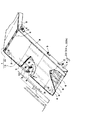
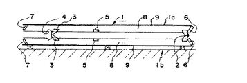
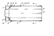
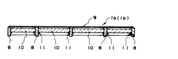
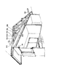
以下、この発明の実施の形態を図面について詳細に説明する。図1はこの発明の実施の形態を示す屋根パネルの斜視図、図2は屋根パネルを折り重ねた状態を示す正面図、図3はこの発明の実施の形態を示す屋根パネル本体の一部を切欠いた平面図、図4は図3A−A線断面図である。 Hereinafter, embodiments of the present invention will be described in detail with reference to the drawings. 1 is a perspective view of a roof panel showing an embodiment of the present invention, FIG. 2 is a front view showing a state in which the roof panel is folded, and FIG. 3 is a part of a roof panel main body showing the embodiment of the present invention. FIG. 4 is a sectional view taken along line AA in FIG. 3.
屋根パネル1は、棟木位置に相当する頂部より一方側に傾斜して位置する一方の屋根パネル本体1aと他方側に傾斜して位置する他方の屋根パネル本体1bとが、頂部に相当する位置においてヒンジ2にて回動可動に連結されている。このヒンジ2にて連結されている部分が、この発明でいう連結部に相当する。従って、符号2はヒンジとしても連結部としても使用する。
前記一方と他方の屋根パネル本体1a、1bには、一方と他方の屋根パネル本体1a、1bをヒンジ(連結部)2を頂部として山形にして屋根相当部に設置したとき軒桁に係止して山形形状を維持するストッパ3が設けられている。
The
The one and the other
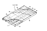
前記屋根パネル本体1a、1bの構成は特に制限はなく、種々の構成を選択できるが、全体の形状は屋根組みに使用するため平面視長方形が好ましい。本例では、屋根パネル本体1a、1bとして、頂部側に位置する棟側部材としての棟板6と軒桁側に位置する軒側部材としての軒板7とが所定間隔で同方向に配置され、この棟板6と軒板7との間に複数の垂木8が架設され、この垂木8上に野地板9が設けられていると共に、この野地板9の裏面側に断熱材10が設けられている構成を示している。
前記一方の屋根パネル本体1aの棟板6と他方の屋根パネル本体1bの棟板6とは、山形形状にして設置するとき、図1に示すように板面が互に当接し合う角度に設けると、一方と他方の屋根パネル本体1a、1bの山形形状の保持の向上に寄与するので好ましい。これにより一方と他方の屋根パネル本体1a、1bの山形形状の保持が強固となる。
The configuration of the
When the
ヒンジ2としては特に限定されるものではなく、従来公知のものでよい。図5はヒンジの一例を示す分解斜視図である。このヒンジ2は、一方のヒンジ片2aが一方の屋根パネル本体1aの垂木8に固定部材(釘)13で固定され、他方のヒンジ片2bが他方の屋根パネル本体1bの垂木8に固定部材13で固定され、このヒンジ片2a、2bを枢軸12となるボルト12aで枢着し、ナット12bでボルト12aの抜け止めをしたものである。本例では、図1に示すように屋根パネル本体1a、1bの両側をヒンジ2で連結した場合を示している。
前記ストッパ3は、屋根パネル1を山形にして設置したとき、軒桁に係止して屋根パネル本体1a、1bの山形形状を保持できる構成のものであればよい。好ましい一例を図6に示す。図6はストッパの一例を示す分解斜視図である。このストッパ3は、ストッパ片3aを、垂木8の側面に固定部材(釘)13で固定して設けている。本例では、図1に示すようにストッパ3が屋根パネル本体1a、1bの両側に設けられている。
また、垂木8には下面に切欠4が設けられていると望ましい。この切欠4は、ストッパ3が軒桁22に係止したとき、軒桁22に当接する位置に設けられるものであって、これにより垂木8の下面の切欠4が軒桁22の角部に嵌合して載置されるので好ましい。この切欠4は、必ずしも必要ではないが、切欠4がないと垂木8と軒桁22とが角で接触することになるので好ましくない。
The
The stopper 3 only needs to be configured so that when the
The
また、断熱材10も必ずしも必要ないが、設けると屋根の内外からの熱の遮断をすることができ、それにより室内の熱の逃げるのを防止し外気を遮断できるので、冬は室内の暖かさを保持できるし、夏は外気の暑さを遮断できて好ましい。本例では、野地板9の裏面側に図4に示すように断熱材止め11で断熱材10を設けた場合を示している。
Further, although the
しかして、この屋根パネル1は、一方と他方の屋根パネル本体1a、1bのヒンジ2での連結部において山形とすることができ、この山形はストッパ3を軒桁22に係止して山形形状を保持することができるので、屋根パネル1を山形にして屋根相当部に設置するだけで施工できる。また、屋根パネル1の一方と他方の屋根パネル本体1a、1bは、ヒンジ2にて回動可能に連結されているので、屋根パネル1は図2に示すように連結部2を中心に回動して折り重ねることができる。
Thus, the
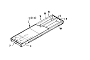
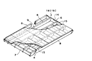
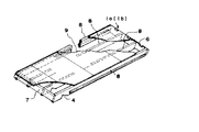
図8乃至図11は、屋根パネル本体の変型例を示す一部切欠の斜視図であり、ヒンジ、ストッパ、断熱材等は省略して示している。図8は垂木8が5本の場合であり、図9は垂木8が3本の場合であり、図10は垂木8の他にけらば垂木15も併用した場合であり、図11は垂木8が4本の場合であり、他は前記実施の形態と同様であるので同一構成要素には同一符号を付して他の説明は省略する。なお、屋根パネル本体1a(1b)の棟板6には、通気孔14を設けてもよい。
このように屋根パネル1は、種々の変形が可能であり、一方の屋根パネル本体1aと他方の屋根パネル本体1bの形状、構造は、同じでなくてもよい。屋根は、一方側に傾斜する屋根と他方側に傾斜する屋根とが全て同じはなく、種々のものがある。従って、建設する家屋の構成に対応して一方の屋根パネル本体1aと他方の屋根パネル本体1bの、大きさ、形状、構造を選択する。
FIGS. 8 to 11 are partially cutaway perspective views showing modifications of the roof panel body, with hinges, stoppers, heat insulating materials and the like omitted. 8 shows a case where there are five
Thus, various deformation | transformation is possible for the
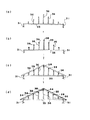
次に、前記屋根パネル1を使用しての屋根組構造の施工方法を説明する。図12は屋根組構造の施工方法を工程順(a)(b)(c)(d)に示した説明図である。
先ず、図12(a)に示すように屋根パネル1をクレーン等で吊り上げるために、折り重ねられて載置されている屋根パネル本体1a、1bに吊り部材16のフック16cを引っ掛ける。一方と他方の屋根パネル本体1a、1bには、図1及び図7に示すようなフック部材5が設けられている。本例では図7に示すようにフック部材5が垂木8の側面に固定部材(釘)13で固定されて設けられている。吊り部材16のフック16cはこのフック部材5に引っ掛けられる。吊り部材16は基材16aより2本のワイヤ16bが吊り下げられ、このワイヤ16bの先端にフック16cが設けられたものである。
次に図12(b)に示すように屋根パネル1を吊り部材16を介してクレーン等で吊り上げる。この時、屋根パネル本体1a、1bが折り重ねられた状態で、連結部2が上部として吊り上げると、図12(b)で鎖線で示すように一方と他方の屋根パネル本体1a、1bは連結部2を中心に両側に開いてゆき、遂には図12(c)に示すように山形の形状となって吊り上げられる。この山形の形状は、図1に示すように一方の屋根パネル本体1aの棟板6と他方の屋根パネル本体1bの棟板6とが当接することによって決定される。この棟板6は、屋根パネル本体1a、1bでの山形をどの程度にするかによって、予め設定された角度に設けられている。
Next, a construction method of the roof assembly structure using the
First, as shown in FIG. 12A, in order to lift the
Next, as shown in FIG. 12B, the
次に、図12(d)に示すように支柱21、軒桁22a、22b及び小屋梁23等で構成する構造体の上に、前記吊り上げた屋根パネル1を載置する。この時、連結部2を頂部とする山形にした状態でストッパ3を軒桁22a、22bに係止させて載置する。図13は、この構造体の上に屋根パネル1が載置された状態を斜視図で示している。
構造体は常法に従って予め構築される。例えば、所定の間隔で、表側に位置する軒桁22aを支持する支柱21と、裏側に位置する軒桁22bを支持する支柱21とを立設し、この表側に位置する軒桁22aを支持する支柱21上には表側に位置する軒桁22aを架設し、裏側に位置する軒桁22bを支持する支柱21上には裏側に位置する軒桁22bを架設し、この表側と裏側に位置する軒桁22a、22b間には小屋梁23を架設することによって構築する。
Next, as shown in FIG. 12 (d), the suspended
The structure is pre-constructed according to a conventional method. For example, the
このような屋根組構造の施工方法によれば、図13に示すような屋根パネル1は、棟木位置に相当する頂部より一方側に傾斜して位置する一方の屋根パネル本体1aと他方側に傾斜して位置する他方の屋根パネル本体1bとが、頂部に相当する位置において回動可動に連結された連結部2となっており、この一方と他方の屋根パネル本体1a、1bには、一方と他方の屋根パネル本体1a、1bを連結部2を頂部として山形にして屋根相当部に設置したとき軒桁22a、22bに係止して山形形状を維持するストッパ3が設けられており、
この屋根パネル1が一方と他方の屋根パネル本体1a、1bを連結部2を頂部として山形にして屋根相当部に設置され、
支柱21に支持されて架け渡された表側に位置する軒桁22aに、一方の屋根パネル本体1aのストッパ3が係止され、支柱21に支持されて架け渡された裏側に位置する軒桁22bに、他方の屋根パネル本体1bのストッパ3が係止されて山形形状に維持され、
前記表側に位置する軒桁22aと裏側に位置する軒桁22bとの間には小屋梁23が架設されている屋根組構造を容易に施工することができる。
According to the construction method of such a roof assembly structure, the
This
A stopper 3 of one roof panel main body 1a is locked to an eaves girder 22a positioned on the front side supported and supported by the
It is possible to easily construct a roof assembly structure in which a
また、前記したような屋根パネル1は、棟木位置に相当する頂部より一方側に傾斜して位置する一方の屋根パネル本体1aと他方側に傾斜して位置する他方の屋根パネル本体1bとが、頂部に相当する位置において回動可動に連結された連結部2となっており、この一方と他方の屋根パネル本体1a、1bには、一方と他方の屋根パネル本体1a、1bを連結部2を頂部として山形にして屋根相当部に設置したとき軒桁22a、22bに係止して山形形状を維持するストッパ3が設けられており、
この屋根パネル1が一方と他方の屋根パネル本体1a、1bを連結部2を頂部として山形にして屋根相当部に設置され、
支柱21に支持されて架け渡された表側に位置する軒桁22aに、一方の屋根パネル本体1aのストッパ3が係止され、支柱21に支持されて架け渡された裏側に位置する軒桁22bに、他方の屋根パネル本体1bのストッパ3が係止されて山形形状に維持され、
前記表側に位置する軒桁22aと裏側に位置する軒桁22bとの間には小屋梁23が架設されている屋根組構造によれば、屋根裏に障害物が存在せず、連続した広い屋根裏空間となるので、屋根裏空間を有効に利用できる。
また、屋根パネル1は、ストッパ3が軒桁22a、22bに係止して山形形状を保持し、表側と裏側の軒桁22a、22b間には小屋梁23が架設されているので、軒桁22a、22bは小屋梁23によって広がることが防止され、それ故に屋根パネル1も広がることができない。その結果、屋根荷重は外周の支柱21のみで支えることができる。さらに、小屋梁23上に図14に示すように板材24を敷設(張設)すると剛性を得ることができ、建物のねじれが防止できる。
In addition, the
This
A stopper 3 of one roof panel main body 1a is locked to an eaves girder 22a positioned on the front side supported and supported by the
According to the roof assembly structure in which the
Further, the
この板材24の敷設(張設)は、前記施工工程における小屋梁23を架設した後か、または構造体の上に屋根パネル1を設置した後に行えばよい。
また、前記屋根組構造によれば、小屋梁23の中間に位置する支柱(図12(d)の支柱21aに相当)は、小屋梁23の「たわみ」のみを支える役目に限定される。即ち、この屋根組構造では、従来の屋根を構成する垂木、棟木、母屋材を経て小屋束にて小屋梁に伝えられる屋根荷重がないので、小屋梁23を支える中間の支柱の本数を少なくすることができ、その結果、当該階の空間は広くとることができ、間仕切りの自由度も広がる。
The laying (stretching) of the
Further, according to the roof assembly structure, the column (corresponding to the column 21a in FIG. 12D) located in the middle of the
なお、前記実施の形態は、この発明を制限するものではなく、この発明は要旨を逸脱しない範囲において種々の変形が許容される。 The above embodiment does not limit the present invention, and various modifications are allowed without departing from the spirit of the present invention.
1 屋根パネル
1a 一方の屋根パネル本体
1b 他方の屋根パネル本体
2 ヒンジ(連結部)
3 ストッパ
4 切欠
5 フック部材
6 棟板(棟側部材)
7 軒板(軒側部材)
8 垂木
9 野地板
10 断熱材
21 支柱
22、22a、22b 軒桁
23 小屋梁
24 板材
DESCRIPTION OF
3 Stopper 4
7 eaves board (eave side member)
8
Claims (11)
この屋根パネルが一方と他方の屋根パネル本体を連結部を頂部として山形にして屋根相当部に設置され、
支柱に支持されて架け渡された表側に位置する軒桁に、一方の屋根パネル本体のストッパが係止され、支柱に支持されて架け渡された裏側に位置する軒桁に、他方の屋根パネル本体のストッパが係止されて山形形状に維持され、
前記表側に位置する軒桁と裏側に位置する軒桁との間には小屋梁が架設されていることを特徴とする屋根組構造。 The roof panel is movable at a position corresponding to the top, with one roof panel body positioned inclined to one side from the top corresponding to the purlin position and the other roof panel body positioned inclined to the other side. The one and the other roof panel body is locked to the eaves girder when the one and the other roof panel body are installed in the roof equivalent part with the connection part as the top. A stopper is provided to maintain the chevron shape,
This roof panel is installed in the roof equivalent part with one and the other roof panel body as a mountain with the connecting part as the top,
The stopper of one roof panel body is locked to the eaves girder that is supported on the front and spanned by the support, and the other roof panel is secured to the eaves girder located on the back side that is supported and supported by the strut. The stopper of the main body is locked and maintained in a mountain shape,
A roof assembly structure in which a roof beam is erected between the eaves girder located on the front side and the eaves girder located on the back side.
この表側に位置する軒桁を支持する支柱上には表側に位置する軒桁を架設し、裏側に位置する軒桁を支持する支柱上には裏側に位置する軒桁を架設し、
この表側と裏側に位置する軒桁間には小屋梁を架設し、この構造体上に、
棟木位置に相当する頂部より一方側に傾斜して位置する一方の屋根パネル本体と他方側に傾斜して位置する他方の屋根パネル本体とが、頂部に相当する位置において回動可動に連結された連結部となっており、この一方と他方の屋根パネル本体には、一方と他方の屋根パネル本体を連結部を頂部として山形にして屋根相当部に設置したとき軒桁に係止して山形形状を維持するストッパが設けられている屋根パネル、を吊り上げ、連結部を頂部とする山形にした状態でストッパを軒桁に係止させて載置することを特徴とする屋根組構造の施工方法。 At predetermined intervals, a column that supports the eaves girder located on the front side and a column that supports the eaves girder located on the back side are erected,
An eaves girder located on the front side is installed on the support column supporting the eaves girder located on the front side, and an eaves girder located on the back side is installed on the support column supporting the eaves girder located on the back side,
Between the front and back eaves girders, shed beams are erected, and on this structure,
One roof panel main body that is inclined to one side from the top corresponding to the purlin position and the other roof panel main body that is inclined to the other side are rotatably connected at a position corresponding to the top. It becomes a connecting part, and when one or the other roof panel body is installed in the roof equivalent part with the connecting part as the top, the one and the other roof panel body is locked to the eaves girder A roofing structure construction method, wherein a roof panel provided with a stopper for maintaining a roof is lifted, and the stopper is locked to an eaves girder in a mountain shape with a connecting portion as a top.
Priority Applications (1)
| Application Number | Priority Date | Filing Date | Title |
|---|---|---|---|
| JP2004106284A JP2005290793A (en) | 2004-03-31 | 2004-03-31 | Roof panel, roof truss structure using it, and construction method for roof truss structure |
Applications Claiming Priority (1)
| Application Number | Priority Date | Filing Date | Title |
|---|---|---|---|
| JP2004106284A JP2005290793A (en) | 2004-03-31 | 2004-03-31 | Roof panel, roof truss structure using it, and construction method for roof truss structure |
Publications (1)
| Publication Number | Publication Date |
|---|---|
| JP2005290793A true JP2005290793A (en) | 2005-10-20 |
Family
ID=35324042
Family Applications (1)
| Application Number | Title | Priority Date | Filing Date |
|---|---|---|---|
| JP2004106284A Pending JP2005290793A (en) | 2004-03-31 | 2004-03-31 | Roof panel, roof truss structure using it, and construction method for roof truss structure |
Country Status (1)
| Country | Link |
|---|---|
| JP (1) | JP2005290793A (en) |
Cited By (3)
| Publication number | Priority date | Publication date | Assignee | Title |
|---|---|---|---|---|
| KR20200045777A (en) * | 2018-10-23 | 2020-05-06 | 골드홈공업 주식회사 | Structure of truss panel for a wooden house |
| JP2021147982A (en) * | 2020-03-24 | 2021-09-27 | 積水化学工業株式会社 | Ridge roof unit |
| JP2023009434A (en) * | 2021-07-07 | 2023-01-20 | 清水建設株式会社 | Roof, moving facility and building |
-
2004
- 2004-03-31 JP JP2004106284A patent/JP2005290793A/en active Pending
Cited By (5)
| Publication number | Priority date | Publication date | Assignee | Title |
|---|---|---|---|---|
| KR20200045777A (en) * | 2018-10-23 | 2020-05-06 | 골드홈공업 주식회사 | Structure of truss panel for a wooden house |
| KR102116777B1 (en) * | 2018-10-23 | 2020-05-29 | 골드홈공업 주식회사 | Structure of truss panel for a wooden house |
| JP2021147982A (en) * | 2020-03-24 | 2021-09-27 | 積水化学工業株式会社 | Ridge roof unit |
| JP2023009434A (en) * | 2021-07-07 | 2023-01-20 | 清水建設株式会社 | Roof, moving facility and building |
| JP7820106B2 (en) | 2021-07-07 | 2026-02-25 | 清水建設株式会社 | Roofs, mobile facilities and buildings |
Similar Documents
| Publication | Publication Date | Title |
|---|---|---|
| US6490840B1 (en) | Hurricane tie system for retrofit on existing structures | |
| JP2005290793A (en) | Roof panel, roof truss structure using it, and construction method for roof truss structure | |
| JP6640162B2 (en) | Roof construction method, rafter panel, roof structure and house | |
| JP5455496B2 (en) | Roof structure of wooden building and its construction method | |
| JP5474721B2 (en) | Building roof structure | |
| JP6910769B2 (en) | Wooden building structure | |
| JP4891758B2 (en) | Multi-storey greenhouse | |
| JPH07238625A (en) | Roof structure and roof unit in eaves section | |
| JP2003239444A (en) | Roof structure of residence | |
| JP7748839B2 (en) | Housing | |
| JPH0247449A (en) | Folding roof unit | |
| GB2560803A (en) | A roofing component | |
| JP2806754B2 (en) | Roof panel and roof structure | |
| JP4694947B2 (en) | Roof telescopic truss and roof structure | |
| JP4189475B2 (en) | Roof beam support structure | |
| JP2916106B2 (en) | Building | |
| JP3749578B2 (en) | building | |
| JPH06330639A (en) | Temporary tent equipped with opening/closing mechanism | |
| GB2355274A (en) | Roofing with prefabricated panels | |
| JPH01210535A (en) | How to install roof/floor panels | |
| JPH09291635A (en) | Gassho beam roof frame | |
| JP3485825B2 (en) | Solar panels | |
| SU1620557A1 (en) | Space block of coating | |
| WO1998021426A1 (en) | A roof for a house | |
| JPH04194151A (en) | Roof |
Legal Events
| Date | Code | Title | Description |
|---|---|---|---|
| A711 | Notification of change in applicant |
Free format text: JAPANESE INTERMEDIATE CODE: A711 Effective date: 20060120 |
|
| A521 | Written amendment |
Free format text: JAPANESE INTERMEDIATE CODE: A821 Effective date: 20060120 |
|
| A521 | Written amendment |
Free format text: JAPANESE INTERMEDIATE CODE: A523 Effective date: 20060403 |
|
| A977 | Report on retrieval |
Free format text: JAPANESE INTERMEDIATE CODE: A971007 Effective date: 20060713 |
|
| A131 | Notification of reasons for refusal |
Free format text: JAPANESE INTERMEDIATE CODE: A131 Effective date: 20061227 |
|
| A02 | Decision of refusal |
Free format text: JAPANESE INTERMEDIATE CODE: A02 Effective date: 20070507 |