JP2005290782A - Detaching fixture - Google Patents

Detaching fixture Download PDF

Info

Publication number
JP2005290782A
JP2005290782A JP2004106010A JP2004106010A JP2005290782A JP 2005290782 A JP2005290782 A JP 2005290782A JP 2004106010 A JP2004106010 A JP 2004106010A JP 2004106010 A JP2004106010 A JP 2004106010A JP 2005290782 A JP2005290782 A JP 2005290782A
Authority
JP
Japan
Prior art keywords
garter
sheet
plate
grip portion
rail
Prior art date
Legal status (The legal status is an assumption and is not a legal conclusion. Google has not performed a legal analysis and makes no representation as to the accuracy of the status listed.)
Pending
Application number
JP2004106010A
Other languages
Japanese (ja)
Inventor
Kazuharu Mori
和晴 森
Takahiro Shimabukuro
孝博 島袋
Shusui Tanaka
秋水 田中
Current Assignee (The listed assignees may be inaccurate. Google has not performed a legal analysis and makes no representation or warranty as to the accuracy of the list.)
Daiwa House Industry Co Ltd
Original Assignee
Daiwa House Industry Co Ltd
Priority date (The priority date is an assumption and is not a legal conclusion. Google has not performed a legal analysis and makes no representation as to the accuracy of the date listed.)
Filing date
Publication date
Application filed by Daiwa House Industry Co Ltd filed Critical Daiwa House Industry Co Ltd
Priority to JP2004106010A priority Critical patent/JP2005290782A/en
Publication of JP2005290782A publication Critical patent/JP2005290782A/en
Pending legal-status Critical Current

Links

Images

Landscapes

  • Tents Or Canopies (AREA)

Abstract

<P>PROBLEM TO BE SOLVED: To provide a detaching fixture which facilitates detachment of a tube member or a clip member functioning as a mounting tool for mounting a temporary building sheet on pipe members. <P>SOLUTION: The detaching fixture is formed of a plate-like grip portion G1, and first and second projected pieces G2, G4 protruding like a plate from both longitudinal ends of the grip portion G1. The first and second projected pieces G2, G4 each have a width narrower than that of the grip portion G1, and the tip of each of the lug pieces is formed like a thin plate so as to be insertable into a gap between the tube member or the clip member and a member under the same. Further the first projected piece G2 has a bent portion at its proximal end and a protrusion G3 having a predetermined height is formed on a convexly curved side of the bent portion. Furthermore the second projected piece G4 is extended from one end portion of the longitudinal end face of the grip portion G1. <P>COPYRIGHT: (C)2006,JPO&NCIPI

Description

本発明は、建築物の上方に張設される仮設テント等のシート材を梁部材に固定するクリップ等の取付具の取り外しを容易にするための取り外し治具に関する。   The present invention relates to a removal jig for facilitating removal of a fixture such as a clip for fixing a sheet material such as a temporary tent stretched above a building to a beam member.

仮設建築用シートを仮設建築物の骨組みを構成するパイプ材に簡易に着脱でき、且つ、シートを密閉状態で確実堅固に張設できる仮設建築用シートの取付具が知られている(例えば、特許文献1参照)。
特開2000−45534号公報(第2−3頁、図4、図6)
Temporary building seat fixtures are known in which the temporary building sheet can be easily attached to and detached from the pipe material constituting the framework of the temporary building, and the seat can be securely and firmly stretched in a sealed state (for example, patents) Reference 1).
JP 2000-45534 A (page 2-3, FIG. 4, FIG. 6)

特許文献1の仮設建築用シートの取付具は、パイプ材に巻付けたシートを、円弧状の断面を有する2つの挟み片で両側から挟み込むように構成されている。そして、両挟み片の蝶着部にジグザグ状のスプリングを着脱可能なスプリング係合溝が設けられ、この係合溝にスプリングを取り付けると、スプリングの弾力によってシートが押圧挟持されて、パイプ材に固定されている。このような取付具を使用すると、スプリングの着脱が容易とされているので、チューブ状の取付具を用いて、パイプ材にシートを容易に固定することができ、かつ、容易に取り外すことができる。   The fixture of the temporary construction sheet of Patent Document 1 is configured to sandwich a sheet wound around a pipe material from two sides with two sandwich pieces having an arcuate cross section. Then, a spring engaging groove to which a zigzag spring can be attached and detached is provided at the hinge part of both sandwiching pieces, and when the spring is attached to this engaging groove, the sheet is pressed and clamped by the elasticity of the spring, and the pipe material is It is fixed. When such a fixture is used, it is easy to attach and detach the spring, so that the sheet can be easily fixed to the pipe member using the tube-like fixture and can be easily detached. .

しかし、特許文献1の取付具は、特殊な構成を有しているため、入手が困難であり、また自ら製作するとコスト高になるという問題点があった。
一方、市場流通品のクリップ材等をシート固定用の取付具として使用すれば、そのような取付具は容易かつ安価に入手することができる。例えば、図13、図15においてシート80を固定するのに使用しているチューブ材81及びクリップ82は、市場流通品であり、容易かつ安価に入手できるとともに、これらを組み合わせて使用することで、シート80を管状部材に強固に固定することができる。
However, since the fixture of patent document 1 has a special structure, it was difficult to obtain, and there was a problem that it would be expensive if manufactured by itself.
On the other hand, if a commercially available clip material or the like is used as a fixture for fixing the seat, such a fixture can be obtained easily and inexpensively. For example, the tube material 81 and the clip 82 used to fix the sheet 80 in FIGS. 13 and 15 are commercially available products, and can be obtained easily and inexpensively. The sheet 80 can be firmly fixed to the tubular member.

ところが、このようなチューブ材81及びクリップ82のような取付具は、所定長さの
C字型断面の筒状材の内部に管状部材及びシート材を押し込み、管状部材と筒状材との間でシートを挟み込むことにより、シートを固定するものである。そして、無理やり筒状材の内部に押し込んだシート及び管状部材から筒状材を引き剥がそうとすると、かなりの力が必要とされていた。従って、シートを管状部材から取り外す際に、指の力だけで引き剥がそうとすると、作業者の負担が大きくなっていた。そして、それにもかかわらず、このようなチューブ材81及びクリップ82の取り外しを容易とするための専用の治具等は知られていなかった。
However, such a fixture such as the tube member 81 and the clip 82 pushes the tubular member and the sheet member into the cylindrical member having a C-shaped cross section having a predetermined length so that the space between the tubular member and the tubular member is reduced. The sheet is fixed by sandwiching the sheet. And when it was going to peel off a cylindrical material from the sheet | seat and the tubular member forcibly pushed into the inside of a cylindrical material, considerable force was required. Therefore, when removing the sheet from the tubular member, if an attempt is made to peel it off with only the force of a finger, the burden on the operator is increased. And nevertheless, a dedicated jig or the like for facilitating the removal of the tube material 81 and the clip 82 has not been known.

本発明は、上記のような問題に鑑み、市販品のチューブ材81及びクリップ82のような略C字型断面の筒状材を管状部材から取り外す作業、すなわち嵌着部材を被嵌着部材から取り外す作業を容易とするための取り外し治具を提供することを目的とする。   In view of the above problems, the present invention is a work for removing a tubular material having a substantially C-shaped cross section, such as a commercially available tube material 81 and a clip 82, from the tubular member, that is, the fitting member from the fitting member. An object of the present invention is to provide a removal jig for facilitating the removal work.

前記課題は、請求項1に記載の取り外し治具によれば、突条部に嵌着された嵌着部材を離脱させるための取り外し治具であって、板状の握り部と、該握り部の長手方向の端部から各々板状に延出する第1の突片部、第2の突片部、を有し、前記第1の突片部及び第2の突辺部は、前記握り部よりも幅狭に形成され、かつ各々の先端に前記嵌着部材と前記突条部との隙間に挿入可能な係止部が形成され、前記第1の突片部は屈曲部を有し、該屈曲部において凸形状をなす側の面には所定高さの突起部が設けられ、前記第2の突片部は、前記握り部の長手方向の端面の一方の端部から延出すること、により解決される。   According to the detachment jig according to claim 1, the subject is a detachment jig for detaching the fitting member fitted to the ridge, and includes a plate-like grip portion and the grip portion. A first projecting piece portion and a second projecting piece portion each extending in a plate shape from the end in the longitudinal direction of the first projecting portion, and the first projecting piece portion and the second projecting side portion are the grips. A locking portion that is formed narrower than the portion and can be inserted into the gap between the fitting member and the protruding portion is formed at each tip, and the first protruding piece portion has a bent portion. In addition, a protrusion having a predetermined height is provided on the surface of the bent portion that has a convex shape, and the second protrusion piece extends from one end of the end face in the longitudinal direction of the grip portion. That is solved.

このように、請求項1に記載の取り外し治具は、嵌着部材と被嵌着部材との隙間に挿入可能な薄板状の第1の突片部を有している。この第1の突片部は屈曲部を有し、この屈曲部の凸形状をなす側の面には突起部が形成されているので、この突起部を支点として、第1の突片部の先端を回動させることができる。従って、第1の突片部を嵌着部材と被嵌着部材との隙間に挿入した後、突起部を被嵌着部材の表面に当接させ、この突起部を支点として握り部に押圧力を加えると、てこの原理により第1の突片部の先端が被嵌着部材の表面から嵌着部材ごと上昇される。これにより、より少ない力で嵌着部材を被嵌着部材から離脱させることができる。従って、作業者の負担が軽減され、嵌着部材の取り外しが容易とされる。   As described above, the removal jig according to the first aspect has the thin plate-like first protruding piece portion that can be inserted into the gap between the fitting member and the fitting member. Since the first protrusion has a bent portion, and a protrusion is formed on the surface of the bent portion on the convex side, the protrusion of the first protrusion is used as a fulcrum. The tip can be rotated. Therefore, after the first projecting piece is inserted into the gap between the fitting member and the fitting member, the projection is brought into contact with the surface of the fitting member, and the pressing force is applied to the grip portion using the projection as a fulcrum. Is added, the tip of the first projecting piece is raised together with the fitting member from the surface of the fitting member by the lever principle. Thereby, the fitting member can be detached from the fitting member with less force. Therefore, the burden on the operator is reduced and the fitting member can be easily removed.

また、請求項1に記載の取り外し治具は、嵌着部材と被嵌着部材との隙間に挿入可能な薄板状の第2の突片部を有し、この第2の突片部は、前記握り部よりも幅狭に形成され、かつ握り部の長手方向の端面の一方の端部から延出している。要するに、第2の突片部は、握り部の角部から延出している。従って、この第2の突片部を嵌着部材と被嵌着部材との隙間に挿入した後、握り部に対して長手方向を軸として回動させる力を加えると、それに伴って第2の突片部が回動され、嵌着部材と被嵌着部材の隙間に挿入された部分が回動され、隙間が拡げられる。つまり、第2の突片部よりも握り部のほうが幅広に形成されているため、握り部を回動させると、てこの原理により、より少ない力で第2の突片部が回動されて、嵌着部材と被嵌着部材の隙間を拡げることができる。従って、作業者の負担が軽減され、嵌着部材の取り外しが容易とされる。   Further, the removal jig according to claim 1 has a thin plate-like second projecting piece portion that can be inserted into a gap between the fitting member and the fitted member, and the second projecting piece portion includes: It is formed narrower than the grip portion and extends from one end portion of the end surface in the longitudinal direction of the grip portion. In short, the second projecting piece extends from the corner of the grip. Accordingly, after inserting the second projecting piece portion into the gap between the fitting member and the fitting member, if a force for rotating the grip portion around the longitudinal direction is applied, the second portion is accompanied accordingly. The projecting piece is rotated, the portion inserted in the gap between the fitting member and the fitting member is turned, and the gap is widened. That is, since the grip part is formed wider than the second protrusion part, when the grip part is rotated, the second protrusion part is rotated with less force by the lever principle. The gap between the fitting member and the fitting member can be widened. Therefore, the burden on the operator is reduced and the fitting member can be easily removed.

このとき、請求項2に記載のように、前記握り部の板面には、長手方向に沿って隆起部が形成されていると好適である。このように構成すると、握り部の板面が作業者の手のひらに沿った形状とされ、握りやすく、力を加えやすい。従って、作業者の負担が軽減され、嵌着部材の取り外しが容易とされる。   At this time, as described in claim 2, it is preferable that the plate surface of the grip portion is formed with a raised portion along the longitudinal direction. If comprised in this way, the plate | board surface of a grip part will be made into the shape along the operator's palm, and it will be easy to hold and it will be easy to apply force. Therefore, the burden on the operator is reduced and the fitting member can be easily removed.

以上のように、本発明によれば、以下のような効果を奏する。
(イ)第1の突片部を嵌着部材と被嵌着部材との隙間に挿入し、突起部を被嵌着部材の表面に当接させて握り部に押圧力を加えると、てこの原理により、より少ない力で嵌着部材を被嵌着部材から離脱させることができる。従って、作業者の負担が軽減され、嵌着部材の取り外しが容易とされる。
(ロ)第2の突片部を嵌着部材と被嵌着部材との隙間に挿入し、握り部を回動させると、てこの原理により、より少ない力で嵌着部材と被嵌着部材の隙間を拡げることができる。
(ハ)握り部の板面に、長手方向に沿って隆起部が形成されていると、握りやすく、作業者が上述の押圧力及び回動力を加えやすい。従って、作業者の負担が軽減され、嵌着部材の取り外しが容易とされる。
As described above, according to the present invention, the following effects can be obtained.
(A) When the first projecting piece is inserted into the gap between the fitting member and the fitting member, the protrusion is brought into contact with the surface of the fitting member and a pressing force is applied to the grip portion, the lever According to the principle, the fitting member can be detached from the fitting member with less force. Therefore, the burden on the operator is reduced and the fitting member can be easily removed.
(B) When the second projecting piece is inserted into the gap between the fitting member and the fitting member and the gripping portion is rotated, the fitting member and the fitting member are reduced with less force by the lever principle. Can be widened.
(C) When the raised portion is formed along the longitudinal direction on the plate surface of the grip portion, it is easy to grip and the operator can easily apply the above-mentioned pressing force and turning force. Therefore, the burden on the operator is reduced and the fitting member can be easily removed.

本発明の実施の形態について、図面を参照して説明する。また、以下に説明する配置、形状等は、本発明を限定するものではなく、本発明の趣旨に沿って各種改変することができることは勿論である。   Embodiments of the present invention will be described with reference to the drawings. Further, the arrangement, shape, and the like described below do not limit the present invention, and various modifications can be made in accordance with the spirit of the present invention.

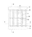
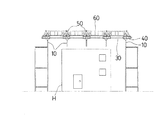
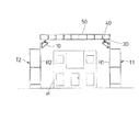
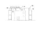
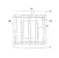
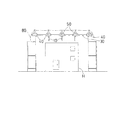
図1乃至図16は本発明の一実施形態を示す図で、図1は実施例の仮設テントの平面図、図2及び図3は実施例の仮設テントの断面図(図2は図1のA−A断面図、図3は図1のB−B断面図)、図4乃至図7は実施例のシートの張設方法を示す説明図、図8は仮設足場にレール、ローラー架台、ガーターを取り付けた状態を示す斜視図、図9は実施例のガーターパーツの接合方法を示す説明図、図10はガーターとつなぎ材の接合部を示す斜視図、図11及び図12は実施例のガーターのレベルを合わせるための束部材を示す説明図、図13は実施例のシートがガーターの上から固定された状態を示す説明図である。
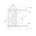
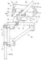
また、図14はシートの固定状態を解除するときに使用する取り外し治具を示す説明図、図15は取り外し治具を用いてクリップを外す手順を示す説明図、図16は実施例の仮設テントのシートに設けられたドレーンの配置を示す説明図、である。
1 to 16 are views showing an embodiment of the present invention. FIG. 1 is a plan view of a temporary tent according to the embodiment. FIGS. 2 and 3 are cross-sectional views of the temporary tent according to the embodiment. AA sectional view, FIG. 3 is a sectional view taken along the line BB of FIG. 1, FIGS. 4 to 7 are explanatory views showing a method of stretching the seat of the embodiment, and FIG. 8 is a temporary scaffold with rails, roller mounts, garters FIG. 9 is an explanatory view showing a method for joining garter parts according to the embodiment, FIG. 10 is a perspective view showing a joint portion between the garter and the connecting material, and FIGS. 11 and 12 are garters according to the embodiment. FIG. 13 is an explanatory view showing a state in which the sheet of the embodiment is fixed from above the garter.
14 is an explanatory view showing a removal jig used to release the fixed state of the sheet, FIG. 15 is an explanatory view showing a procedure for removing the clip using the removal jig, and FIG. 16 is a temporary tent of the embodiment. It is explanatory drawing which shows arrangement | positioning of the drain provided in the sheet | seat of this.

(仮設テント及び仮設テント用梁部材の構成)
本実施形態の仮設テントSは、仮設足場Tに支持されるブラケット10に固定されるレール支持材20と、該レール支持材20に固定されるレール30と、該レール30に装着されるローラー架台40と、該ローラー架台の上面に取り付けられるガーター50と、隣接するガーター50同士を所定間隔で連結するつなぎ材60と、前記ガーター50に着脱可能な束部材70と、前記ガーター50及びつなぎ材60の上に張設されるシート80と、該シート80に設けられた排水用のドレーン90と、を有して構成されている。
なお、上述のレール30が本発明のレール部材に相当し、ガーター50が本発明の梁部材に相当し、シート80が本発明のシート部材に相当する。
(Configuration of temporary tent and beam member for temporary tent)
The temporary tent S of this embodiment includes a rail support member 20 fixed to a bracket 10 supported by a temporary scaffold T, a rail 30 fixed to the rail support member 20, and a roller mount attached to the rail 30. 40, a garter 50 attached to the upper surface of the roller mount, a connecting member 60 that connects adjacent garters 50 at a predetermined interval, a bundle member 70 that can be attached to and detached from the garter 50, the garter 50, and the connecting member 60. And a drainage drain 90 provided on the sheet 80, and a drainage drain 90 provided on the sheet 80.
The rail 30 described above corresponds to the rail member of the present invention, the garter 50 corresponds to the beam member of the present invention, and the seat 80 corresponds to the sheet member of the present invention.

仮設テントSは、図1に示すように、建物Hを挟んで対向する位置に設けられた仮設足場T1及びT2によって支持されている。なお、図1乃至図3においてシート80は図示を省略している。また、図1において図2及び図3に示されているブラケット10、ローラー架台40は図示を省略している。   As shown in FIG. 1, the temporary tent S is supported by temporary scaffolds T <b> 1 and T <b> 2 provided at positions facing each other across the building H. 1 to 3, the sheet 80 is not shown. In FIG. 1, the bracket 10 and the roller mount 40 shown in FIGS. 2 and 3 are not shown.

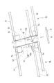
図3に示すように、この仮設足場T1及びT2の内側(建物側)の縦枠材R1及びR2の上端部には、ブラケット10が各々略同一高さに取り付けられている。ブラケット10は、図8に示すように、縦フレーム材11と、縦フレーム材11に固定された略水平な横フレーム材12と、を有して構成されている。縦フレーム材11と縦枠材R1,R2とは単管連結材13によって固定され、横フレーム材12は縦フレーム材11の上端から建物側に向けて延出されている。各々の横フレーム材12の上側には、図8に示すように、断面コの字型のレール支持材20の片方のフランジ面が単管クランプ14を介して固定されている。そして、レール支持材20のもう一方のフランジ部の先端にはレール30が固定されている。   As shown in FIG. 3, brackets 10 are attached to substantially the same height at the upper ends of the vertical frame members R1 and R2 inside (building side) the temporary scaffolds T1 and T2. As shown in FIG. 8, the bracket 10 includes a vertical frame member 11 and a substantially horizontal horizontal frame member 12 fixed to the vertical frame member 11. The vertical frame member 11 and the vertical frame members R1 and R2 are fixed by a single pipe connecting member 13, and the horizontal frame member 12 extends from the upper end of the vertical frame member 11 toward the building. As shown in FIG. 8, one flange surface of the U-shaped rail support member 20 is fixed to the upper side of each horizontal frame member 12 via a single tube clamp 14. A rail 30 is fixed to the tip of the other flange portion of the rail support member 20.

レール30は、上述のように、略直線上に並んだ複数の縦枠材R1に、ブラケット1及びレール支持材20を介して複数箇所で支持され、略水平に保持されている。同様に、別のレール30が、略直線上に並んだ複数の縦枠材R2に、ブラケット1及びレール支持材20を介して複数箇所で支持され、略水平に保持されている。つまり、仮設足場T1、T2からそれぞれ建物側にレール30が架設されおり、建物Hを挟んで略平行に2本のレール30が架設されている。
なお、本実施形態では、レール30は、2.3mm厚の鋼材からなる直径48.6mmのメッキ鋼管が使用されている。
As described above, the rail 30 is supported by a plurality of vertical frame members R1 arranged on a substantially straight line at a plurality of positions via the bracket 1 and the rail support member 20, and is held substantially horizontally. Similarly, another rail 30 is supported by a plurality of vertical frame members R2 arranged on a substantially straight line via a bracket 1 and a rail support member 20 at a plurality of locations, and is held substantially horizontally. That is, the rails 30 are erected on the building side from the temporary scaffolds T1 and T2, respectively, and the two rails 30 are erected substantially in parallel with the building H interposed therebetween.
In this embodiment, the rail 30 is a plated steel pipe having a diameter of 48.6 mm made of a steel material having a thickness of 2.3 mm.

ローラー架台40は、図8に示すように、走行部41の上に架台部42が接合されている。走行部41は、リップ溝形鋼の断面形状を有するローラー受け材43の内部に、複数のローラー44をコの字型に配設して形成されている。架台部42には、後述するガーター50の下端面の部材が接合される。
このローラー架台40は、略コの字型に配設された各々回転自在なローラー44で囲まれる空間にレール30が挿通されて装着される。このように装着すると、レール30が該ローラー44の回転面に3方向から当接されて支持され、ローラー架台40がレール30に沿って走行自在とされる。また、ローラー44はローラー受け材43の長さ方向に沿って複数配置されているので、レール30に対してローラー受け材43が平行に装着される。
As shown in FIG. 8, the roller base 40 has a base part 42 joined to a traveling part 41. The traveling portion 41 is formed by arranging a plurality of rollers 44 in a U-shape inside a roller receiving member 43 having a lip groove steel cross-sectional shape. A member on a lower end surface of a garter 50 described later is joined to the gantry 42.
The roller mount 40 is mounted by inserting the rail 30 into a space surrounded by each rotatable roller 44 arranged in a substantially U-shape. When mounted in this manner, the rail 30 is brought into contact with and supported by the rotation surface of the roller 44 from three directions, and the roller mount 40 can travel along the rail 30. In addition, since a plurality of rollers 44 are arranged along the length direction of the roller receiving member 43, the roller receiving member 43 is mounted in parallel to the rail 30.

ガーター50は、建物Hを挟んで略平行に架設される一対のレール30,30に架け渡される部材であり、1本の上弦材51及び2本の下弦材52,52を略正三角形の薄板状の梁用プレート53の各々の頂点に接合して構成されている。ガーター50は、両端部が各々ローラー架台40の架台部42に取り付けられている。そして、ガーター50は、両端のローラー架台40,40が略平行なレール30,30に各々装着されることにより、建物上空を走行自在とされる。なお、本実施形態では図6のようなローラー架台40を用いてガーター50を走行自在に構成したが、このような形状に限定されず、レール30に対して走行自在な構成であれば、どのような構成であってもよい。   The garter 50 is a member that is bridged between a pair of rails 30, 30 that are laid substantially in parallel across the building H. The garter 50 is composed of one upper chord member 51 and two lower chord members 52, 52 that are substantially equilateral triangular thin plates. Each beam plate 53 is joined to each apex. Both ends of the garter 50 are attached to the gantry 42 of the roller gantry 40. And the garter 50 is made to run freely over the building by attaching the roller mounts 40, 40 at both ends to the substantially parallel rails 30, 30, respectively. In the present embodiment, the garter 50 is configured to run freely using the roller mount 40 as shown in FIG. 6. However, the garter 50 is not limited to such a shape, and any configuration can be used as long as it can run with respect to the rail 30. Such a configuration may be adopted.

上弦材51及び下弦材52,52は、いずれも1.6mm厚の鋼材からなるメッキ鋼管が使用されている。その径寸法は19.1mmとされている。
梁用プレート53は、3.2mm厚の鋼板からなり、略正三角形の底辺から頂点までの寸法が200mmとされている。なお、この梁用プレート53が、本発明の連結材に相当する。また、この梁用プレート53は、ガーター50の長さ方向に455mm間隔に配置されている。すなわち、モジュール寸法(910mm)の半分のピッチで配置されている。また、梁用プレート53のプレート面はガーター50の長さ方向に対して略垂直とされている。
Each of the upper chord material 51 and the lower chord material 52, 52 is a plated steel pipe made of a steel material having a thickness of 1.6 mm. Its diameter is 19.1 mm.
The beam plate 53 is made of a steel plate having a thickness of 3.2 mm, and the dimension from the base to the apex of the substantially equilateral triangle is 200 mm. The beam plate 53 corresponds to the connecting material of the present invention. The beam plates 53 are arranged at 455 mm intervals in the length direction of the garter 50. That is, they are arranged at a pitch that is half the module dimension (910 mm). The plate surface of the beam plate 53 is substantially perpendicular to the length direction of the garter 50.

梁用プレート53と上弦材51または下弦材52,52は、各々補強プレート54を介して接合されている。この補強プレート54は、約50mm角の3.2mm厚の鋼板であって、一端面が梁用プレート53のプレート面に溶接され、該溶接面と隣り合う端面が上弦材51または下弦材52,52の側面に溶接されている。
また、梁用プレート53には、その略中央に直径50mmの円形開口53aが設けられており、部材の軽量化が図られている。また、この円形開口53aの周囲に複数の直径13mmのボルト接合穴53bが設けられている。ボルト接合穴53bのうち3個は、円形開口53aの中心から三角形の各頂点に向かって60mm離間した位置を中心として設けられている。また、別のボルト接合穴53bは、円形開口53aの中心から三角形の各辺に向かう垂線上であって、各辺から25mm内側の位置を中心として設けられている。
The beam plate 53 and the upper chord material 51 or the lower chord material 52, 52 are joined via a reinforcing plate 54, respectively. The reinforcing plate 54 is a steel plate having a thickness of about 50 mm and a thickness of 3.2 mm. One end surface of the reinforcing plate 54 is welded to the plate surface of the beam plate 53, and the end surface adjacent to the welded surface is the upper chord member 51 or the lower chord member 52, It is welded to the side surface of 52.
Further, the beam plate 53 is provided with a circular opening 53a having a diameter of 50 mm at substantially the center thereof, thereby reducing the weight of the member. Further, a plurality of bolt joint holes 53b having a diameter of 13 mm are provided around the circular opening 53a. Three of the bolt joint holes 53b are provided centering on a position 60 mm away from the center of the circular opening 53a toward each vertex of the triangle. Further, the other bolt joint hole 53b is provided on a perpendicular line from the center of the circular opening 53a to each side of the triangle and at a position 25 mm inside from each side.

本実施形態では、長尺部材のガーター50を人力で架設するために、互いに着脱可能な複数のガーターパーツ55が長さ方向に連結されたガーターを作業床上で組み立てて架設している。各々のガーターパーツ55は、その最大長さが3640mmとされ、その最大重量が11kgとされている。なお、このガーターパーツ55が、本発明の組立部材に相当する。
これらの部材の運搬に際し、各々の部材を作業者が手で持つときに苦痛を感じないようにするためには、各々の部材の重量を10kgとする必要があるとされている。すなわち、10kgが作業者に苦痛を感じさせないためのガイドラインの値である。本実施形態のガーターパーツ55は最大重量が11kgとされており、このガイドラインの重量を越えているが、その超過量はわずかである。従って、作業者が本実施形態のガーターパーツ55を運搬しても、それほど作業に苦痛を感じることがない。また、3640mmよりも短いガーターパーツは10kg以下とされており、運搬に際して作業者に苦痛を感じさせることがない。
In this embodiment, in order to construct the garter 50 which is a long member manually, a garter in which a plurality of garter parts 55 which can be attached to and detached from each other are connected in the length direction is assembled and constructed on the work floor. Each garter part 55 has a maximum length of 3640 mm and a maximum weight of 11 kg. The garter part 55 corresponds to the assembly member of the present invention.
In transporting these members, it is said that the weight of each member needs to be 10 kg so that the operator does not feel pain when holding the member by hand. That is, 10 kg is a guideline value for preventing the worker from feeling pain. The garter part 55 of the present embodiment has a maximum weight of 11 kg, which exceeds the weight of this guideline, but the excess amount is slight. Therefore, even if the worker carries the garter part 55 of the present embodiment, the work is not so painful. Moreover, the garter parts shorter than 3640 mm are 10 kg or less, and do not make a worker feel pain at the time of conveyance.

このように、仮設テントSの構成部材を、全て人力で作業床上へ運搬することができ、かつ作業床上で組立または解体が可能な部材で構成することによって、重機を用いずに梁部材を架け渡すことができ、仮設テントの設置・解体を行うことができる。従って、コストが削減される。また、重機の設置スペースが確保できない現場でも仮設テントを設置することができる。   As described above, the structural members of the temporary tent S can be transported to the work floor by human power and can be assembled or dismantled on the work floor. It can be handed over, and temporary tents can be installed and dismantled. Therefore, the cost is reduced. Temporary tents can also be installed at sites where heavy equipment installation space cannot be secured.

本実施形態の仮設テントは、建物または敷地の大きさによって大きさが異なるものとされる。このような場合に対応するため、ガーターパーツ55として複数種類の長さのものが準備されていると好適である。これにより、様々な長さのガーターを容易に組み立てることができる。例えば、単位モジュール寸法を基準として、その整数倍または整数分の1のガーターパーツを準備する。本実施形態では、建物のモジュール寸法が910mmとされており、その2分の1の455mmを基準に寸法展開されているので、455mmを基準寸法として、この整数倍の寸法展開でガーターパーツを準備する。このようにすると、モジュール展開された建物に対応した寸法のガーターを容易に組み立てることができる。但し、本実施形態では、上述のように作業性及び設置・解体の容易性を考慮して、ガーターパーツの最大長さはモジュール寸法の4倍の3640mmとされる。
また、ガーターの両端は上述した架台部42に固定されるため、ガーターの両端に使用する組立部材として、固定しろを考慮した端部専用の長さのものを準備してもよい。
The temporary tent of the present embodiment varies in size depending on the size of the building or site. In order to cope with such a case, it is preferable that a plurality of types of garter parts 55 are prepared. Thereby, garters of various lengths can be easily assembled. For example, a garter part having an integer multiple or a fraction of an integer is prepared based on the unit module dimensions. In this embodiment, the module size of the building is 910 mm, and the size is developed based on 455 mm, which is a half of the module size. To do. If it does in this way, the garter of the dimension corresponding to the building where the module was developed can be assembled easily. However, in the present embodiment, in consideration of workability and ease of installation / disassembly as described above, the maximum length of the garter part is 3640 mm, which is four times the module size.
In addition, since both ends of the garter are fixed to the above-described gantry 42, an assembly member used for both ends of the garter may be prepared with a length only for the end considering the fixing margin.

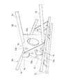
図9に、ガーターパーツ55の接合方法を示す。各々のガーターパーツ55の両端には梁用プレート53が取り付けられており、この梁用プレート53を接合相手のガーターパーツ55端部の梁用プレート53と重ね合わせる。それと共に、上弦材51及び下弦材52,52の端部の開口を接合相手の部材の対応する上弦材、下弦材の開口に対向させる。そして、所定長さの棒状のピン部材Pの両端を、それぞれ対向する開口に挿入し、ピン部材Pを、矢印に示すように、両側から鋼管の内部に収納する。このようにすると、ピン部材Pを介して上弦材51、下弦材52が直線状に連結される。   FIG. 9 shows a method for joining the garter parts 55. Beam plates 53 are attached to both ends of each garter part 55, and this beam plate 53 is overlapped with the beam plate 53 at the end of the garter part 55 to be joined. At the same time, the openings of the ends of the upper chord material 51 and the lower chord material 52, 52 are opposed to the corresponding openings of the upper chord material and the lower chord material of the member to be joined. Then, both ends of a rod-shaped pin member P having a predetermined length are inserted into the openings facing each other, and the pin member P is housed in the steel pipe from both sides as indicated by arrows. If it does in this way, the upper chord material 51 and the lower chord material 52 will be connected linearly via the pin member P.

このピン部材Pの略中央には、少なくとも1つの突起Qが形成されている。突起Qが形成されていると、その端部から鋼管の内部に差し込まれたピン部材Pは、突起Qの位置以上に深く鋼管の内部に挿入されることはない。従って、必ずピン部材Pの略中央部がガーターパーツ55の連結面、すなわち鋼管と対向する鋼管の境界面に位置されるようにピン部材が保持され、位置ずれを起こすことがない。   At least one protrusion Q is formed in the approximate center of the pin member P. When the protrusion Q is formed, the pin member P inserted into the steel pipe from the end thereof is not inserted deeper than the position of the protrusion Q into the steel pipe. Therefore, the pin member is always held so that the substantially central portion of the pin member P is positioned on the connecting surface of the garter part 55, that is, the boundary surface of the steel pipe facing the steel pipe, and no positional deviation occurs.

そして、重ね合わせた梁用プレート53のボルト接合穴53bにボルトMを挿通してナットNを締め付け、梁用プレート53同士を固定する。図9では一箇所しかボルトが締め付けられていないが、ボルトMは、十分な接合強度を得られる数であれば良く、全てのボルト接合穴53bに取り付けても良いし、一部のボルト接合穴53bのみに取り付けても良い。また、ボルト以外にも、着脱可能な締結材であれば使用することができる。   Then, the bolt M is inserted into the bolt joint hole 53b of the overlapped beam plate 53, the nut N is tightened, and the beam plates 53 are fixed to each other. In FIG. 9, only one bolt is tightened, but the bolt M may be a number that can obtain a sufficient joint strength, and may be attached to all the bolt joint holes 53 b or a part of the bolt joint holes. You may attach only to 53b. In addition to bolts, any detachable fastening material can be used.

つなぎ材60は、図1に示すように、隣り合うガーター50の各々の略中央部に連結されている。このつなぎ材60は、隣り合うガーター同士を所定の間隔に保持すると共に、シート80で被覆されたとき、仮設テントの内側からシート80を支持するものである。このようなつなぎ材60を設けた理由については、後述する。   As shown in FIG. 1, the connecting member 60 is connected to the substantially central portion of each adjacent garter 50. The connecting member 60 holds the adjacent garters at a predetermined interval and supports the sheet 80 from the inside of the temporary tent when covered with the sheet 80. The reason for providing such a connecting material 60 will be described later.

図10に、つなぎ材60とガーター50との接合部を示す。本実施形態のつなぎ材60は、上弦材61と下弦材62とを矩形のつなぎプレート63で連結して平面的なフレーム状に構成されている。つなぎ用プレート63は、少なくともつなぎ材60の両端部に設けられ、その所定位置に開口63a及びボルト接合穴63bが設けられている。従って、つなぎ材60をガーター50に接合するには、ガーター50の梁用プレート53と、つなぎ材60のつなぎ用プレート63とを重ね合わせる。そして、ボルト接合穴53b、63bにボルトMを挿通してナットNを取り付け、固定すればよい。   In FIG. 10, the junction part of the connection material 60 and the garter 50 is shown. The connecting material 60 of the present embodiment is formed in a planar frame shape by connecting an upper chord material 61 and a lower chord material 62 by a rectangular connecting plate 63. The connecting plate 63 is provided at least at both ends of the connecting material 60, and an opening 63a and a bolt joint hole 63b are provided at predetermined positions thereof. Therefore, in order to join the connecting material 60 to the garter 50, the beam plate 53 of the garter 50 and the connecting plate 63 of the connecting material 60 are overlapped. Then, the bolt M may be inserted into the bolt joint holes 53b and 63b, and the nut N may be attached and fixed.

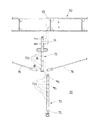
束部材70は、ガーター50に接合されてレベル調整を行う際に使用される部材である。この束部材70は、ガーター用束72と、レベル調整束73とを備え、ガーター用束72の胴部に100mm間隔で形成された長さ調整穴72aと、レベル調整束73の胴部に100mm間隔で形成された長さ調整穴73aとを位置合わせしてボルトを挿通して固定することにより、所望の長さに調整することができる。   The bundle member 70 is a member that is used when level adjustment is performed by joining the garter 50. The bundle member 70 includes a garter bundle 72 and a level adjustment bundle 73. The length adjustment holes 72a formed in the trunk portion of the garter bundle 72 at intervals of 100 mm, and the trunk portion of the level adjustment bundle 73 are 100 mm. It is possible to adjust to a desired length by aligning the length adjusting holes 73a formed at intervals and inserting and fixing bolts.

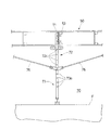
束用プレート71はガーター用束72の先端に固定されており、梁用プレート53と略同一形状とされている。従って、束部材70とガーター50とを接合するには、梁用プレート53と束用プレート71とを重ねてボルトで接合する。また、レベル調整束73は、その下端内部に接合された不図示の長ナット74に螺合された位置調整ネジ75をまわして長さ方向に前進または後退させることにより、レベルの微調整を行うことができる。
図11はガーター用束72、レベル調整束73、及びガーター50の接合方法を説明する分解斜視図である。また、図12は作業床上に組み立てられた束部材70を示す説明図である。なお、レベル調整の手順については、仮設テント及び仮設テント用梁部材の設置方法の欄で後述する。
The bundle plate 71 is fixed to the tip of the garter bundle 72 and has substantially the same shape as the beam plate 53. Therefore, in order to join the bundle member 70 and the garter 50, the beam plate 53 and the bundle plate 71 are overlapped and joined with a bolt. Further, the level adjustment bundle 73 performs fine adjustment of the level by turning a position adjustment screw 75 screwed to a long nut 74 (not shown) joined to the lower end of the level adjustment bundle 73 and moving it forward or backward in the length direction. be able to.
FIG. 11 is an exploded perspective view for explaining a method of joining the garter bundle 72, the level adjustment bundle 73, and the garter 50. FIG. Moreover, FIG. 12 is explanatory drawing which shows the bundle member 70 assembled on the work floor. The level adjustment procedure will be described later in the column of the installation method of the temporary tent and the temporary tent beam member.

シート80は、ガーター50及びつなぎ材60によって支持されており、ガーター50及びつなぎ材60を覆うように被せられ、ガーター50の上弦材51に対して固定されている。本実施形態のシート80は、公知の防水シートが使用されている。シート80には、ガーター50に対して固定される位置にあらかじめ合わせマークが印刷されている。また、上弦材51と当接する取付部分にはあらかじめ増し張りが施され、補強が施されている。   The sheet 80 is supported by the garter 50 and the connecting material 60, is covered so as to cover the garter 50 and the connecting material 60, and is fixed to the upper chord material 51 of the garter 50. As the sheet 80 of the present embodiment, a known waterproof sheet is used. An alignment mark is printed in advance on the sheet 80 at a position fixed to the garter 50. Further, the attachment portion that comes into contact with the upper chord material 51 is pre-stretched and reinforced.

後述するように、本実施形態のシート80の張設方法では、複数本のガーター50をレール上の一箇所に寄せ集め、ガーター50と隣り合うガーター50とが近接した状態で、ガーター間にシート80がたるんだ状態となるように取り付ける。そして、ガーター50を移動させてシート80を展伸させ、ガーター50が所定位置まで移動されたときに、シート80が略水平に緊張されるように構成されている。そのため、本実施形態の合わせマークは、シート80を緊張した状態における隣合うガーター50間の距離に、シートを上弦材51に固定するための固定しろを加えた間隔で印刷されている。
このような合わせマークが印刷されていると、合わせマークを基準に、たるんだ状態でシート80をガーター50に固定しておき、その後シート80を展伸したときには、シート80がちょうど略水平に緊張されるようにすることができる。従って、取り付け時にその都度シートのどの位置で固定すればよいか測って取り付ける必要がなく、取付作業が簡易化される。また、正確な位置で固定することができ、展伸されたシートが略水平に緊張されるようにすることができる。
As will be described later, in the method for stretching the sheet 80 according to the present embodiment, a plurality of garters 50 are gathered together at one place on the rail, and the garters 50 and the adjacent garters 50 are in close proximity to each other. Install so that 80 is in a slack state. The garter 50 is moved to expand the sheet 80. When the garter 50 is moved to a predetermined position, the sheet 80 is tensioned substantially horizontally. Therefore, the alignment mark of the present embodiment is printed at an interval obtained by adding a fixing margin for fixing the sheet to the upper chord material 51 to the distance between the adjacent garters 50 in a state where the sheet 80 is tensioned.
When such an alignment mark is printed, the sheet 80 is fixed to the garter 50 in a slack state with the alignment mark as a reference, and when the sheet 80 is expanded after that, the sheet 80 is stretched almost horizontally. Can be done. Accordingly, there is no need to measure and attach at which position of the seat each time it is attached, and the attaching operation is simplified. Further, the sheet can be fixed at an accurate position, and the stretched sheet can be tensioned substantially horizontally.

本実施形態の合わせマークは、シート80の両側縁に所定間隔で印刷されており、この合わせマークをガーター50の上弦材の両端部に合わせてシートを固定すればよいが、合わせマークの位置はこのような位置に限定されず、シート80の固定位置を定められる位置であれば、どのような位置に印刷してもよい。また、シート80の両側縁だけでなく、シート80の内部側にも印刷しておき、ガーター50の長さ方向の中間部に固定される内部側の固定位置についても、正確に位置決めできるようにしておいてもよい。
また、合わせマークは印刷によるものに限定されず、合わせ位置が認識できるものであればどのようなものでもよい。例えば、所定の位置決め部材を取り付けておく方法でもよい。
The alignment marks of the present embodiment are printed on both side edges of the sheet 80 at a predetermined interval. The alignment marks may be fixed to both ends of the upper chord material of the garter 50, and the alignment marks are positioned at the positions. The position is not limited to such a position, and printing may be performed at any position as long as the fixing position of the sheet 80 can be determined. In addition, printing is performed not only on both side edges of the sheet 80 but also on the inner side of the sheet 80 so that the fixing position on the inner side that is fixed to the intermediate portion in the longitudinal direction of the garter 50 can be accurately positioned. You may keep it.
The alignment mark is not limited to printing, and any alignment mark can be used as long as the alignment position can be recognized. For example, a method of attaching a predetermined positioning member may be used.

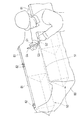
図13に実施例のシート80がガーター50の上から被せられて一部が固定された状態を示す。この図において、シート80に覆われたガーターの形状を点線で示す。シート80を上弦材51に対して固定する方法は、以下のようなものである。シート80を被せた上から、所定長さの略C字型断面を有するチューブ材81を上弦材51に嵌着する。これにより、上弦材51とチューブ材81との間でシート80が挟持され、固定される。そして、チューブ材81の両端部等のはずれ易い箇所には、さらにチューブ材81の外側からクリップ82を嵌着して、より強固に固定する。   FIG. 13 shows a state in which the sheet 80 of the embodiment is covered from the top of the garter 50 and a part thereof is fixed. In this figure, the shape of the garter covered with the sheet 80 is indicated by a dotted line. A method of fixing the sheet 80 to the upper chord material 51 is as follows. A tube material 81 having a substantially C-shaped cross section having a predetermined length is fitted onto the upper chord material 51 from above the sheet 80. As a result, the sheet 80 is sandwiched and fixed between the upper chord member 51 and the tube member 81. And the clip 82 is further fitted from the outer side of the tube material 81 to the part where the both ends of the tube material 81 are easy to come off, and it fixes more firmly.

チューブ材81及びクリップ82は着脱可能な挟持部材である。チューブ材81は弾力性のある樹脂製品からなり、C字型断面の開口部分を拡げてシート80及び上弦材を押し込み、挟み込むことができる。クリップ82は、C字型断面の短い筒材82aの外側からバネ材82bで挟み込むものであって、バネ材82bを筒材82aの一端に軸支させ、回動させることによって、挟み込みまたは取り外しできるものである。
なお、シート80の固定状態を解除する手順及び解除の際に使用される取り外し治具Gについては、後述する。
The tube material 81 and the clip 82 are detachable clamping members. The tube material 81 is made of an elastic resin product, and the sheet 80 and the upper chord material can be pushed in between the opening portion of the C-shaped cross section and sandwiched. The clip 82 is sandwiched by the spring member 82b from the outside of the tubular member 82a having a short C-shaped cross section, and can be sandwiched or removed by pivoting and rotating the spring member 82b to one end of the tubular member 82a. Is.
The procedure for releasing the fixed state of the seat 80 and the removal jig G used for the release will be described later.

次に、つなぎ材60を設けた理由について説明する。図16に仮設テントSの平面図を示す。この図において、シート80に被覆されたガーター50、レール30、つなぎ材60、は点線で示されており、仮設足場T及び建物Hは図示を省略している。図16に図示されるように、シート80には、仮設テントSの外側と内側とを連通するドレーン90a乃至90hが設けられている。そして、このドレーン90a乃至90hには、各々仮設テントSの内側に連通する不図示の排水ホース91a乃至91hが接続されている。排水ホースは、排水の必要がないときには取外して建築工事の邪魔にならないようにすることもできる。そして、排水ホースを取り外したときには、ドレーン90a乃至90hには防水キャップ等を嵌着してふさいでおくこともできる。   Next, the reason for providing the connecting material 60 will be described. FIG. 16 is a plan view of the temporary tent S. In this figure, the garter 50 covered with the sheet 80, the rail 30, and the connecting material 60 are indicated by dotted lines, and the temporary scaffold T and the building H are not shown. As shown in FIG. 16, the seat 80 is provided with drains 90 a to 90 h that communicate the outside and the inside of the temporary tent S. Then, drain hoses 91a to 91h (not shown) communicating with the inside of the temporary tent S are connected to the drains 90a to 90h, respectively. The drain hose can be removed so that it does not interfere with the construction work when drainage is not required. When the drainage hose is removed, a waterproof cap or the like can be fitted to the drains 90a to 90h and blocked.

シート80の上に雨水が溜まると、溜まった雨水がこのドレーン90にうまく流入されれば、排水ホース91によってテント外へ排出することができる。本実施形態の仮設テントSでは、上述したようにガーター50の上弦材51にシート80が固定されて支持されているので、上弦材51を境にガーター50の両側に雨水が振り分けられる。同様に、つなぎ材60の両側に雨水が振り分けられる。つまり、つなぎ材60を設けることにより、隣り合うガーター50、つなぎ材60、及びレール30によって囲まれる矩形の構面が一つの排水負担領域となり、排水負担領域が2分割される。そして、これらのつなぎ材60を境に隣り合う排水負担領域は、排水系統が別となる。   When rainwater accumulates on the seat 80, if the accumulated rainwater flows into the drain 90 well, it can be discharged out of the tent by the drainage hose 91. In the temporary tent S of the present embodiment, since the sheet 80 is fixed and supported on the upper chord material 51 of the garter 50 as described above, rainwater is distributed to both sides of the garter 50 with the upper chord material 51 as a boundary. Similarly, rainwater is distributed to both sides of the connecting material 60. That is, by providing the connecting material 60, the rectangular construction surface surrounded by the adjacent garter 50, the connecting material 60, and the rail 30 becomes one drainage load area, and the drainage load area is divided into two. And the drainage load area | region becomes another in the drainage burden area | region adjacent on these borders 60 as a boundary.

本願出願人は、まず、つなぎ材60を設けない構成で仮設テントの試作実験を行った。このとき、ドレーンの位置は図16と同様に設けられていた。すなわち、隣り合うガーター50及び一対のレール30で囲まれる構面に各々2ヶ所のドレーン90が設けられていた。また、この配置以外の配置でも、試験を行った。その結果、つなぎ材を設けない構成では、雨水が必ずしもドレーン90に流入されず、排水を確実に行うことができないことを知った。
つまり、実験の結果によれば、つなぎ60が設けられていない状態、すなわち排水負担領域が広い場合には、排水負担領域内に局部的な水たまりが形成された。このような水たまりは、その発生位置が一定とされていなかった。そして、いったんそのような水たまりが形成されると、そこに溜まった雨水は、作業者がドレーンの位置に移動させて排水させない限り、いつまでも排水されない。このように、雨水が集中した部分のシート80及びシート80を支持する部材の負担が増大し、仮設テントSの耐久性に悪影響を与える。また、建築工事の作業性に悪影響を与える。
The applicant of the present application first conducted a trial experiment of a temporary tent in a configuration in which the connecting material 60 was not provided. At this time, the drain position was provided as in FIG. That is, two drains 90 are provided on the surface surrounded by the adjacent garter 50 and the pair of rails 30. In addition, the test was performed in other arrangements. As a result, it has been found that rainwater does not necessarily flow into the drain 90 and drainage cannot be reliably performed in a configuration in which no connecting material is provided.
That is, according to the result of the experiment, when the connection 60 is not provided, that is, when the drainage burden area is wide, a local puddle is formed in the drainage burden area. Such puddles were not generated at constant positions. Once such a puddle is formed, the rainwater collected there is not drained indefinitely unless the operator moves it to the drain position and drains it. As described above, the load on the portion of the sheet 80 where rainwater is concentrated and the member that supports the sheet 80 is increased, and the durability of the temporary tent S is adversely affected. In addition, it adversely affects the workability of construction work.

そこで、本願出願人は、工夫を重ねた結果、つなぎ材60で隣り合うガーター50の中央部分を連結して排水負担領域を2分割し、つなぎ材を境として両側に雨水が振り分けられるようにした。そして、図16のように、排水負担領域、すなわち、隣り合うガーター50、つなぎ材60、及びレール30によって囲まれる矩形の構面の対角線の交点に各々のドレーン90a乃至90hを位置させるようにした。このようにすると、局部的に水たまりができる等の排水不良が発生せず、各々のドレーン90a乃至90hから良好に排水されることを知った。
なお、ガーター50の支持スパンがもっと長尺とされている場合には、つなぎ材60は必ずしもガーター50の中央でなく、例えばガーター50の支持スパン、すなわちレール30、30間の距離を三分割した位置に設けられていてもよい。このときには、ドレーン90は、隣り合うガーター50、つなぎ材60、及び該つなぎ材60と隣り合うつなぎ材によって囲まれる矩形の構面の対角線の交点に位置させると、排水不良が発生しない。
Therefore, as a result of repeated efforts, the applicant of the present application connected the central portions of the adjacent garters 50 with the connecting material 60 to divide the drainage burden area into two parts so that rainwater can be distributed to both sides with the connecting material as a boundary. . And as shown in FIG. 16, each drain 90a thru | or 90h was located in the drainage burden area | region, ie, the intersection of the diagonal of the rectangular composition surface surrounded by the adjacent garter 50, the connecting material 60, and the rail 30. . In this way, it has been found that drainage failure such as local puddles does not occur and drainage from each of the drains 90a to 90h is good.
In addition, when the support span of the garter 50 is made longer, the connecting material 60 is not necessarily the center of the garter 50. For example, the support span of the garter 50, that is, the distance between the rails 30 and 30 is divided into three. It may be provided at a position. At this time, if the drain 90 is positioned at the intersection of the adjacent garter 50, the connecting material 60, and the diagonal of the rectangular composition surrounded by the connecting material adjacent to the connecting material 60, the drainage failure does not occur.

(仮設テント及び仮設テント用梁部材の設置方法)
以下、本実施形態の仮設テントSを設置する手順について説明する。
(1)まず、ブラケット10及び仮設テントSの構成部材を仮設足場T又は建物Hの作業床上に運び上げる。構成部材としては、レール支持材20、レール30、ローラー架台40、ガーターパーツ55、つなぎ材60、ガーター用束72、レベル調整束73、シート80、排水ホース91、シート取付具(チューブ材81、クリップ82)等がある。また、必要工具及び連結用の部材を運び上げる。
(Installation method of temporary tent and beam member for temporary tent)
Hereinafter, a procedure for installing the temporary tent S of the present embodiment will be described.
(1) First, the structural members of the bracket 10 and the temporary tent S are carried on the temporary scaffold T or the work floor of the building H. Constituent members include rail support member 20, rail 30, roller mount 40, garter part 55, tether 60, garter bundle 72, level adjustment bundle 73, sheet 80, drain hose 91, sheet fixture (tube member 81, Clip 82). In addition, necessary tools and connecting members are carried up.

(2)次に、レールを設置する。すなわち、仮設足場Tの縦枠材Rにブラケット10を固定し、レール30をレール支持材20を介してブラケット10の上に固定する。
(3)次に、ガーターパーツを組み立てる。すなわち、ガーターパーツ55の端部の梁用プレート53同士を連結して所定の寸法及び数量のガーター50を組み立てる。そして、ガーター50の両端にローラー架台40を取り付ける。
(4)次に、ガーターをレール間に架け渡す。すなわち、各々のローラー架台40をレール30に取り付けてガーター50を所望の数だけ架け渡す。
(2) Next, a rail is installed. That is, the bracket 10 is fixed to the vertical frame member R of the temporary scaffold T, and the rail 30 is fixed on the bracket 10 via the rail support member 20.
(3) Next, assemble the garter parts. That is, the beam plates 53 at the ends of the garter parts 55 are connected to assemble the garter 50 having a predetermined size and quantity. Then, the roller mounts 40 are attached to both ends of the garter 50.
(4) Next, the garter is bridged between the rails. That is, each roller mount 40 is attached to the rail 30 and a desired number of garters 50 are mounted.

(5)次に、ガーター50にシート80を張設する。まず、全てのガーター50をレール上で一箇所に寄せ集めて、シート80で覆う。そして、予めシートに印刷された合わせマークの位置を各々のガーター50の上弦材51の位置とを合わせてシートをガーター50の上弦材51に固定する。このとき、ガーター50が寄せ集められているので、シート80はガーター50の間にたるんだ状態とされている。図4及び図5がこの状態の仮設テントSを示す。その後、シート80と全てのガーター50との固定作業が終了した後、ガーター50を図4及び図5のA方向にスライドさせて、蛇腹状に配設されていたシート80を展伸させ、ぴんと緊張させる。図6及び図7がこの状態の仮設テントSを示す。 (5) Next, the sheet 80 is stretched on the garter 50. First, all the garters 50 are gathered in one place on the rail and covered with the sheet 80. Then, the position of the alignment mark printed on the sheet in advance is aligned with the position of the upper chord material 51 of each garter 50 to fix the sheet to the upper chord material 51 of the garter 50. At this time, since the garters 50 are gathered together, the sheet 80 is in a state of sagging between the garters 50. 4 and 5 show the temporary tent S in this state. Thereafter, after the fixing operation of the sheet 80 and all the garters 50 is completed, the garter 50 is slid in the direction A in FIGS. 4 and 5 to expand the sheet 80 arranged in a bellows shape. Tension. 6 and 7 show the temporary tent S in this state.

(6)次に、シート80が緊張された状態で、各々のローラー架台40をレール30に対して固定する。仮設テントSの構成の欄では説明を省略したが、ローラー架台には、レール30の真上に位置される部位に、上方から棒状の固定ピンを挿通させることが可能な穴が形成されている。また、レール30には、この固定ピンを挿通させることが可能な固定穴が所定間隔で形成されている。この固定穴を、シートの合わせマークの間隔と対応させて設けておくことにより、シート80が展伸され、ぴんと張られた状態でローラー架台40とレールとを1本の固定ピンで挿通させ、動かないようにすることができる。この方法では、予めレール30に固定穴が形成されているので位置決めが容易となるが、これ以外にも、公知のクランプ等を用いて所望の位置にローラー架台40を固定するようにしてもよい。 (6) Next, in a state where the sheet 80 is in tension, each roller mount 40 is fixed to the rail 30. Although description is omitted in the column of the configuration of the temporary tent S, the roller mount is formed with a hole through which a rod-shaped fixing pin can be inserted from above at a position located directly above the rail 30. . In addition, fixing holes through which the fixing pins can be inserted are formed in the rail 30 at predetermined intervals. By providing this fixing hole in correspondence with the interval between the alignment marks on the sheet, the sheet 80 is stretched and stretched, and the roller mount 40 and the rail are inserted with a single fixing pin. It can be prevented from moving. In this method, since the fixing holes are formed in the rail 30 in advance, positioning becomes easy. However, in addition to this, the roller mount 40 may be fixed at a desired position using a known clamp or the like. .

(7)次に、各々のガーター50の中間部に束部材70を接合してレベル合わせを行う。図11及び図12に示すように、ガーター用束72の一端に固定された束用プレート71とガーター50の梁用プレート53とをボルトで接合する。そして、ガーター50のレベルが最も設計位置に近くなるように、長さ調整穴72aと長さ調整穴73aとを位置合わせしてボルトを挿通し、ガーター用束72とレベル調整束73を接合する。そして、このレベル調整束73を、シート80によって覆われた建物の屋上又は作業床、あるいは仮設足場の作業床、等の上(図12においてFとして示す)に設置する。このように、おおよそのレベルを合わせた後、レベル調整束73の下端に設けた位置調整ネジ75により、レベルの微調整を行う。 (7) Next, the bundle member 70 is joined to the intermediate part of each garter 50, and level adjustment is performed. As shown in FIGS. 11 and 12, the bundle plate 71 fixed to one end of the garter bundle 72 and the beam plate 53 of the garter 50 are joined by bolts. Then, the length adjustment hole 72a and the length adjustment hole 73a are aligned so that the level of the garter 50 is closest to the design position, and a bolt is inserted to join the garter bundle 72 and the level adjustment bundle 73. . Then, the level adjustment bundle 73 is installed on the rooftop or work floor of the building covered with the sheet 80, the work floor of the temporary scaffold, etc. (shown as F in FIG. 12). In this way, after adjusting the approximate level, the level is finely adjusted by the position adjusting screw 75 provided at the lower end of the level adjusting bundle 73.

(8)そして、レベル微調整を行った後、ガーター用束の下端とガーター50の両端のローラー架台4とを、各々ブレース材76によって接合し、張力を与える。これによりガーター50のたわみが改善され、ガーター50が略直線状態に保持される。
(9)次に、隣り合うガーター50の中間部をつなぎ材60で連結する。
(10)最後に、排水ホース91をドレーン90に接続して排水路を確保する。
(8) Then, after performing level fine adjustment, the lower ends of the garter bundle and the roller mounts 4 at both ends of the garter 50 are respectively joined by the brace material 76 to give tension. Thereby, the deflection of the garter 50 is improved, and the garter 50 is held in a substantially straight state.
(9) Next, the intermediate portions of the adjacent garters 50 are connected by the connecting material 60.
(10) Finally, the drainage hose 91 is connected to the drain 90 to secure a drainage channel.

(シートの固定解除方法及び取り外し治具)
本実施形態の仮設テントを解体するときにシート80の固定を解除する方法及びそれに用いる取り外し治具について説明する。
図13では、作業者がシート80の一部の固定状態を途中まで解除した状態を示しているが、シートの固定状態を解除するには、まずクリップ82を取り外し、その後、チューブ材81を取り外す。このとき、作業者は、取り外し治具Gを使用して作業を行う。
図14に取り外し治具Gの斜視図及び側面図を示す。この取り外し治具Gは、片手で握るのに丁度良い寸法の板状の握り部G1と、その一端から所定角度で突出する薄板状の突起部G2と、突起部G2の根元に形成された隆起部G3と、突起部G2と逆の端部に突出する薄板状の突起部G4と、を備えている。
(Sheet release method and removal jig)
A method of releasing the fixation of the sheet 80 when dismantling the temporary tent of the present embodiment and a removal jig used therefor will be described.
FIG. 13 shows a state in which the worker has partially released the fixed state of the sheet 80. To release the fixed state of the sheet, the clip 82 is first removed, and then the tube member 81 is removed. . At this time, the worker performs work using the removal jig G.
FIG. 14 shows a perspective view and a side view of the removal jig G. FIG. The detaching jig G includes a plate-shaped grip portion G1 having a size that is just suitable for gripping with one hand, a thin plate-shaped projection portion G2 that protrudes from one end thereof at a predetermined angle, and a ridge formed at the base of the projection portion G2. A portion G3 and a thin plate-like protrusion G4 protruding at the end opposite to the protrusion G2 are provided.

握り部G1の略中央には、握り部G1の長手方向に沿って、帯状の隆起部が形成されている。そして、この隆起部の両端には穴部が形成されて隆起部の形成が容易とされている。このような隆起部が設けられていることにより、握り部G1は、片手で握ったときの手のひらの形状になじむ形状とされている。そして、このように形成されていると、後述するように握り部G1を回動させるときに押圧力及び回動力を加えやすい。従って、作業者の負担が軽減される。   A belt-like raised portion is formed at the approximate center of the grip portion G1 along the longitudinal direction of the grip portion G1. And the hole part is formed in the both ends of this protruding part, and formation of a protruding part is made easy. By providing such a raised portion, the grip portion G1 has a shape adapted to the shape of a palm when grasped with one hand. And if it forms in this way, when rotating the grip part G1 so that it may mention later, it is easy to apply pressing force and turning force. Therefore, the burden on the operator is reduced.

突起部G2及びG4は、いずれも握り部Gよりも幅狭に形成されており、その先端はチューブ材81又はクリップ82の下の隙間に挿入し易いように薄板状に形成されている。突起部G2は、その根元部で屈曲されており、この屈曲部には、凸形状をなす側の面に隆起部G3が形成されている。突起部G4は、その板面が、握り部G1の板面と同一平面に突出され、かつ、握り部G1の長手方向の端面の一方の端部である角部から延出している。これにより、握り部G1の側縁と突起部G4の側縁とは、段差なく直線状に接続されている。突起部G4は、突起部G2と同一方向に突出されていてもよいが、握り部G1の角部に接続されていることが好ましい。握り部G1の角部に接続されていれば、握り部G1の回動に伴って突起部G4を回動させ、チューブ材81又はクリップ82の下の隙間を拡げようとするときに、てこの原理を利用することができ、より少ない力でチューブ材81又はクリップ82の下の隙間を拡げることができる。   Each of the protrusions G2 and G4 is formed narrower than the grip portion G, and the tip thereof is formed in a thin plate shape so that it can be easily inserted into the gap under the tube material 81 or the clip 82. The protruding portion G2 is bent at the base portion thereof, and a protruding portion G3 is formed on the surface of the bent portion on the convex side. The protruding portion G4 has a plate surface protruding in the same plane as the plate surface of the grip portion G1, and extends from a corner portion which is one end portion of the end surface in the longitudinal direction of the grip portion G1. Thereby, the side edge of the grip part G1 and the side edge of the projection part G4 are connected linearly without a step. The protrusion G4 may protrude in the same direction as the protrusion G2, but is preferably connected to a corner of the grip part G1. If it is connected to the corner of the grip portion G1, the protrusion G4 is rotated with the rotation of the grip portion G1, and the lever is used to widen the gap under the tube material 81 or the clip 82. The principle can be used, and the gap under the tube material 81 or the clip 82 can be expanded with less force.

作業者は、突起部G2を使用するときは、突起部G2をチューブ材81の下の隙間に差し込み、隆起部G3をチューブ材81が取り付けられたシート面に当接させ、握り部G1に対してこのシート面に向かって押下する力を加える。このようにすると、てこの原理により隆起部G3を支点として突起部G2が回動されてシート面から上昇され、チューブ材81がシート80及び上弦材51からひきはがされる。   When the operator uses the protruding portion G2, the operator inserts the protruding portion G2 into the gap below the tube material 81, and makes the raised portion G3 contact the sheet surface to which the tube material 81 is attached. Apply a force to push the lever toward the seat surface. In this way, by the lever principle, the protruding portion G2 is rotated with the raised portion G3 as a fulcrum and lifted from the seat surface, and the tube material 81 is peeled off from the seat 80 and the upper chord material 51.

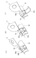
また、図15に突起部G4を使用してクリップ82を外すときの手順を示す。まず、図15(a)に示すように、バネ材82bと筒材82aとの隙間に突起部G4を差し込む。次に、図15(b)に示すように、突起部G4をその延出方向を軸として回動させる。このとき、幅広の握り部G1を回動させることにより、より少ない力で突起部G4を回動させてバネ材82bと筒材82aとの隙間を広げることができる。そして、バネ材82bを回動させて取り外す。そして、図15(c)に示すように、筒材82aとチューブ材81との隙間に突起部G4を差し込み、同様に突起部G4を回動させて筒材82aとチューブ材81との隙間を拡げて、筒材82aをチューブ材81からひきはがす。   FIG. 15 shows a procedure for removing the clip 82 using the projection G4. First, as shown in FIG. 15A, the protruding portion G4 is inserted into the gap between the spring member 82b and the tubular member 82a. Next, as shown in FIG. 15B, the projection G4 is rotated about the extending direction. At this time, by rotating the wide grip portion G1, the protrusion G4 can be rotated with a smaller force to widen the gap between the spring member 82b and the cylindrical member 82a. Then, the spring member 82b is rotated and removed. And as shown in FIG.15 (c), the projection part G4 is inserted in the clearance gap between the cylinder material 82a and the tube material 81, and similarly the projection part G4 is rotated, and the clearance gap between the cylinder material 82a and the tube material 81 is made. The tube material 82a is expanded and peeled off from the tube material 81.

実施例の仮設テントの平面図である。It is a top view of the temporary tent of an Example. 実施例の仮設テントの断面図である。It is sectional drawing of the temporary tent of an Example. 実施例の仮設テントの断面図である。It is sectional drawing of the temporary tent of an Example. 実施例のシートの張設方法を示す説明図である。It is explanatory drawing which shows the tensioning | laying method of the sheet | seat of an Example. 実施例のシートの張設方法を示す説明図である。It is explanatory drawing which shows the tensioning | laying method of the sheet | seat of an Example. 実施例のシートの張設方法を示す説明図である。It is explanatory drawing which shows the tensioning | laying method of the sheet | seat of an Example. 実施例のシートの張設方法を示す説明図である。It is explanatory drawing which shows the tensioning | laying method of the sheet | seat of an Example. 仮設足場にレール、ローラー架台、ガーターを取り付けた状態を示す斜視図である。It is a perspective view which shows the state which attached the rail, the roller mount frame, and the garter to the temporary scaffold. 実施例のガーターパーツの接合方法を示す説明図である。It is explanatory drawing which shows the joining method of the garter parts of an Example. ガーターとつなぎ材の接合部を示す斜視図である。It is a perspective view which shows the junction part of a garter and a connection material. 実施例のガーターのレベルを合わせるための束部材を示す説明図である。It is explanatory drawing which shows the bundle member for adjusting the level of the garter of an Example. 実施例のガーターのレベルを合わせるための束部材を示す説明図である。It is explanatory drawing which shows the bundle member for adjusting the level of the garter of an Example. 実施例のシートがガーターの上から固定された状態を示す説明図である。It is explanatory drawing which shows the state by which the sheet | seat of the Example was fixed from the garter. シートの固定状態を解除する取り外し治具を示す説明図である。It is explanatory drawing which shows the removal jig | tool which cancels | releases the fixing state of a sheet | seat. 取り外し治具を用いてクリップを外す手順を示す説明図である。It is explanatory drawing which shows the procedure which removes a clip using a removal jig | tool. 実施例の仮設テントのシートに設けられたドレーンの配置を示す説明図である。It is explanatory drawing which shows arrangement | positioning of the drain provided in the sheet | seat of the temporary tent of the Example.

符号の説明Explanation of symbols

10 ブラケット、11 縦フレーム材、12 横フレーム材、13 単管連結材、14 単管クランプ、20 レール支持材、30 レール、40 ローラー架台、41 走行部、42 架台部、43 ローラー受け材、44 ローラー、50 ガーター、51 上弦材、52 下弦材、53 梁用プレート、53a 円形開口、53b ボルト接合穴、54 補強プレート、55 ガーターパーツ、60 つなぎ材、61 上弦材、62 下弦材、63 つなぎ用プレート、63a 開口、63b ボルト接合穴、70 束部材、71 束用プレート、72 ガーター用束、72a 長さ調整穴、73 レベル調整束、73a 長さ調整穴、74 長ナット、75 位置調整ネジ、76 ブレース材、80 シート、81 チューブ材、82 クリップ、82a 筒材、82b バネ材、90,90a乃至90h ドレーン、91,91a乃至91h 排水ホース、G 治具、G1 握り部、G2 突起部、G3 隆起部、G4 突起部、F 作業床、H 建物、M ボルト、N ナット、P ピン部材、Q 突起、R,R1,R2 縦枠材、S 仮設テント、T,T1,T2 仮設足場 DESCRIPTION OF SYMBOLS 10 Bracket, 11 Vertical frame material, 12 Horizontal frame material, 13 Single pipe connection material, 14 Single pipe clamp, 20 Rail support material, 30 Rail, 40 Roller mount, 41 Running part, 42 mount part, 43 Roller receiving material, 44 Roller, 50 Garter, 51 Upper chord material, 52 Lower chord material, 53 Beam plate, 53a Circular opening, 53b Bolt joint hole, 54 Reinforcement plate, 55 Garter parts, 60 Connecting material, 61 Upper chord material, 62 Lower chord material, 63 Connecting Plate, 63a opening, 63b Bolt joint hole, 70 Bundle member, 71 Bundle plate, 72 Garter bundle, 72a Length adjustment hole, 73 Level adjustment bundle, 73a Length adjustment hole, 74 Length nut, 75 Position adjustment screw, 76 brace material, 80 sheets, 81 tube material, 82 clips, 82a tube 82b Spring material, 90, 90a to 90h Drain, 91, 91a to 91h Drain hose, G jig, G1 gripping part, G2 protruding part, G3 raised part, G4 protruding part, F working floor, H building, M bolt, N nut, P pin member, Q protrusion, R, R1, R2 vertical frame material, S temporary tent, T, T1, T2 temporary scaffold

Claims (2)

突条部に嵌着された嵌着部材を離脱させるための取り外し治具であって、
板状の握り部と、該握り部の長手方向の端部から各々板状に延出する第1の突片部、第2の突片部、を有し、
前記第1の突片部及び第2の突辺部は、前記握り部よりも幅狭に形成され、かつ各々の先端に前記嵌着部材と前記突条部との隙間に挿入可能な係止部が形成され、
前記第1の突片部は屈曲部を有し、該屈曲部において凸形状をなす側の面には所定高さの突起部が設けられ、
前記第2の突片部は、前記握り部の長手方向の端面の一方の端部から延出することを特徴とする、取り外し治具。
A removal jig for detaching the fitting member fitted to the ridge,
A plate-like grip portion, and a first projecting piece portion and a second projecting piece portion each extending in a plate shape from an end portion in the longitudinal direction of the grip portion,
The first projecting piece portion and the second projecting side portion are formed to be narrower than the grip portion, and can be inserted into the gap between the fitting member and the protruding portion at each tip. Part is formed,
The first protruding piece portion has a bent portion, and a protruding portion having a predetermined height is provided on a surface of the bent portion on the side having a convex shape,
The removal jig, wherein the second projecting piece portion extends from one end portion of the end surface in the longitudinal direction of the grip portion.
前記握り部の板面には、長手方向に沿って隆起部が形成されていることを特徴とする、請求項1に記載の取り外し治具。   The removal jig according to claim 1, wherein a protruding portion is formed along a longitudinal direction on a plate surface of the grip portion.
JP2004106010A 2004-03-31 2004-03-31 Detaching fixture Pending JP2005290782A (en)

Priority Applications (1)

Application Number Priority Date Filing Date Title
JP2004106010A JP2005290782A (en) 2004-03-31 2004-03-31 Detaching fixture

Applications Claiming Priority (1)

Application Number Priority Date Filing Date Title
JP2004106010A JP2005290782A (en) 2004-03-31 2004-03-31 Detaching fixture

Publications (1)

Publication Number Publication Date
JP2005290782A true JP2005290782A (en) 2005-10-20

Family

ID=35324031

Family Applications (1)

Application Number Title Priority Date Filing Date
JP2004106010A Pending JP2005290782A (en) 2004-03-31 2004-03-31 Detaching fixture

Country Status (1)

Country Link
JP (1) JP2005290782A (en)

Similar Documents

Publication Publication Date Title
AU668760B2 (en) Form panel
JP3751708B2 (en) Curing scaffold plate support assembly
US20080277549A1 (en) Beam Flange Clamp
JP2005290782A (en) Detaching fixture
CN215108936U (en) Water-stopping fixing protection combined component for tunnel
JP5290879B2 (en) Folded plate roof power frame body and folded plate roof power frame structure
JP2005290780A (en) Temporary tent and beam member therefor
JP2005290781A (en) Temporary tent
KR101429688B1 (en) Surporting apparatus for establishing railing&#39;s post
JP2019105033A (en) Splice plate holding tool
JP3548426B2 (en) Apparatus and method for mounting stanchion pole
JP3548859B2 (en) Roof mounting equipment
JP2506110Y2 (en) Wall panel mounting furring material
JPH11223009A (en) Construction method of vertical pipe unit and vertical pipe
EP0924364B1 (en) Roofing structure
JP4988941B1 (en) Support jig transfer jig and support transfer method
JPH10183862A (en) Steel frame assembling jig and steel frame assembling method
JP3563279B2 (en) Wall mounting structure
CN119109412B (en) Photovoltaic panel butt joint device and method for photovoltaic construction
JP2002322760A (en) Fixing part structure of membrane member, fixing method, and shape steel for membrane member fixation using therefor
JP3252620U (en) Solar module mounting structure
CN222779056U (en) A quick fixing device for square steel joints
JPH0372165A (en) Lifting fixture
JP4007757B2 (en) Panel mounting structure
JP2025114230A (en) Work plate mounting jig, work plate installation method, and work plate safety equipment

Legal Events

Date Code Title Description
A621 Written request for application examination

Free format text: JAPANESE INTERMEDIATE CODE: A621

Effective date: 20070314

A977 Report on retrieval

Free format text: JAPANESE INTERMEDIATE CODE: A971007

Effective date: 20091030

A131 Notification of reasons for refusal

Effective date: 20091110

Free format text: JAPANESE INTERMEDIATE CODE: A131

A02 Decision of refusal

Free format text: JAPANESE INTERMEDIATE CODE: A02

Effective date: 20100309