JP2005290780A - Temporary tent and beam member therefor - Google Patents
Temporary tent and beam member therefor Download PDFInfo
- Publication number
- JP2005290780A JP2005290780A JP2004106008A JP2004106008A JP2005290780A JP 2005290780 A JP2005290780 A JP 2005290780A JP 2004106008 A JP2004106008 A JP 2004106008A JP 2004106008 A JP2004106008 A JP 2004106008A JP 2005290780 A JP2005290780 A JP 2005290780A
- Authority
- JP
- Japan
- Prior art keywords
- members
- garter
- temporary
- sheet
- temporary tent
- Prior art date
- Legal status (The legal status is an assumption and is not a legal conclusion. Google has not performed a legal analysis and makes no representation as to the accuracy of the status listed.)
- Pending
Links
- 239000000463 material Substances 0.000 claims description 130
- 238000010276 construction Methods 0.000 abstract description 14
- 229910000831 Steel Inorganic materials 0.000 abstract description 13
- 239000010959 steel Substances 0.000 abstract description 13
- 238000000034 method Methods 0.000 description 25
- 238000009434 installation Methods 0.000 description 18
- 238000004519 manufacturing process Methods 0.000 description 5
- 230000003014 reinforcing effect Effects 0.000 description 3
- 230000002411 adverse Effects 0.000 description 2
- 239000000470 constituent Substances 0.000 description 2
- 238000002474 experimental method Methods 0.000 description 2
- 238000013461 design Methods 0.000 description 1
- 230000000694 effects Effects 0.000 description 1
- 239000000203 mixture Substances 0.000 description 1
- 238000012986 modification Methods 0.000 description 1
- 230000004048 modification Effects 0.000 description 1
- 230000002787 reinforcement Effects 0.000 description 1
- 239000011347 resin Substances 0.000 description 1
- 229920005989 resin Polymers 0.000 description 1
- 238000007665 sagging Methods 0.000 description 1
- 238000012360 testing method Methods 0.000 description 1
- 238000009423 ventilation Methods 0.000 description 1
Images

Landscapes
- Tents Or Canopies (AREA)
Abstract
Description
本発明は、仮設足場を利用して建設中の建築物の上方にシート材を張設する仮設テントに係り、特に、必要に応じてシート材が開閉可能とされ、かつ設置及び解体が容易な仮設テントに関する。
また、本発明は、建設中の建築物の上方に張設される仮設テントのシート材を支持する梁部材に係り、特に、設置及び解体が容易な仮設テント用梁部材に関する。
The present invention relates to a temporary tent in which a sheet material is stretched above a building under construction using a temporary scaffold, and in particular, the sheet material can be opened and closed as necessary, and can be easily installed and disassembled. Regarding temporary tents.
The present invention also relates to a beam member for supporting a sheet material of a temporary tent stretched above a building under construction, and more particularly to a beam member for a temporary tent that is easy to install and dismantle.
戸建て住宅などの建物を建築する際に、建物の骨組みや各種資材、或いは作業者などが雨や雪等によって濡れるのを防止すると共に、天候の悪化によって工事が中断されるのを防止するために、建築途中の建物を仮設屋根によってスッポリと覆う技術が提案されている。そして、このような仮設屋根を、仮設足場又は支柱によって支持するものとし、換気や資材搬入などの必要に応じて開閉可能とする技術が知られている(例えば、特許文献1参照)。
また、土木、建築作業現場の仮設建築物の周囲骨組みに開閉可能な仮設屋根を設ける技術が知られている(例えば、特許文献2参照)。この仮設屋根は、仮設建築物の前後の梁に所要数の移動台車を嵌着し、その移動台車に屋根フレームの下端部を取付け、該屋根フレームの上端部に屋根シートのシートジョイントを着脱可能に固定して構成されている。
Moreover, the technique which provides the temporary roof which can be opened and closed to the surrounding framework of the temporary building of a civil engineering and construction work site is known (for example, refer patent document 2). This temporary roof can be fitted with the required number of moving carriages on the beams before and after the temporary building, the lower end of the roof frame is attached to the moving carriage, and the seat joint of the roof sheet can be attached to and detached from the upper end of the roof frame It is fixed and configured.
特許文献1の仮設テントは、平行な2本のレール部材に沿ってシート状のテント部材の両端がスライド可能に構成されている。そして、片方のレール部材は建物の上方を横切るように設置されており、建物の周囲に組み立てられた先行足場又は支柱によって支持されている。このレール部材は両端のみで支持されているため、その支持スパンが大きく、長尺の部材を使用する必要がある。また、このレール部材はテント部材の自重や雨水の荷重、風荷重等の荷重を支持するため断面寸法を大きくする必要がある。このように、特許文献1の仮設テントは、長尺かつ断面寸法の大きいレール部材を使用する必要があり、そのためレール部材の重量が大きくなり、設置に重機が必要とされるという問題点があった。
The temporary tent of
特許文献2の仮設屋根は、屋根シートを支持する屋根フレームが移動台車によって仮設建築物の梁の上をスライドされているため、スムーズに開閉することができる。しかし、この屋根フレームは、1つのフレーム材の支持スパンが、仮設建築物の建物スパンに等しく、支持スパンが大きい。従って、特許文献1の仮設テントと同様に、フレーム材の重量が大きくなり、設置に重機が必要とされるという問題点があった。
The temporary roof of Patent Document 2 can be smoothly opened and closed because the roof frame supporting the roof sheet is slid on the beam of the temporary building by the moving carriage. However, in this roof frame, the support span of one frame member is equal to the building span of the temporary building, and the support span is large. Therefore, like the temporary tent of
本発明は、上記のような問題に鑑み、仮設足場を利用して設置され、炎天、雨天又は吹雪などの悪天候でも建築作業を進行させることが可能な仮設テントであって、必要に応じて開閉可能に構成され、かつ、設置及び解体が容易な仮設テントを提供することを目的とする。また、本発明は、仮設テントのシート材を支持する梁部材に係り、特に、設置及び解体が容易な仮設テント用梁部材を提供することを目的とする。 In view of the problems as described above, the present invention is a temporary tent that is installed using a temporary scaffold and is capable of proceeding with building work even in bad weather such as hot weather, rainy weather, or snowstorm, etc. An object of the present invention is to provide a temporary tent that can be opened and closed and is easy to install and dismantle. The present invention also relates to a beam member that supports a sheet material of a temporary tent, and particularly to provide a beam member for a temporary tent that is easy to install and dismantle.
前記課題は、請求項1に記載の仮設テントによれば、建物又は敷地の上方を覆う仮設テントであって、建物又は敷地の周囲に設置された仮設足場に略水平に架設される一対の略平行なレール部材と、該レール部材の各々に両端が支持されて建物又は敷地の上空に掛け渡され、前記レール部材に沿って走行自在に構成された複数の梁部材と、隣り合う梁部材の間に張設されるシート部材と、を備え、前記梁部材の各々は、互に着脱可能な組立部材を長さ方向に連結して構成されていること、により解決される。
According to the temporary tent according to
このように、請求項1に記載の仮設テントは、シート部材を支持する梁部材が、複数の組立部材を組み立てることにより構成されている。従って、各々の組立部材は作業者が人力で運搬可能な大きさ及び寸法とすることができ、このような組立部材を予め仮設足場又は建物の作業床上に運搬してから長尺の部材に組み立てて設置することができる。
このように構成すると、長尺の梁部材を架けわたす場合でも梁部材の設置に重機を必要としない。また、解体を行う際にも同様に重機を必要としないので、設置、解体が容易である。また、コストが削減される。また、重機の設置スペースが確保できない現場でも仮設テントを設置することができる。
Thus, the temporary tent according to
If comprised in this way, even when extending a long beam member, a heavy machine is not required for installation of a beam member. Similarly, no heavy machinery is required when disassembling, so installation and disassembly are easy. Further, the cost is reduced. Temporary tents can also be installed at sites where heavy equipment installation space cannot be secured.
また、前記課題は、請求項2に記載の仮設テントによれば、前記組立部材は、少なくとも1本の上弦材と、少なくとも2本の下弦材と、前記上弦材及び下弦材に接合された連結材と、を有し、前記連結材は、薄板状のプレートからなり、少なくとも前記組立部材の両端に配設されると共に、他の組立部材の端部に配設された連結材と着脱可能に構成されること、により解決される。 Further, according to the temporary tent according to claim 2, the assembly member includes at least one upper chord member, at least two lower chord members, and a connection joined to the upper chord member and the lower chord member. The connecting member is made of a thin plate-like plate, and is disposed at least at both ends of the assembly member, and is detachable from the connection member disposed at the end of the other assembly member. It is solved by being configured.
このように、請求項2に記載の仮設テントは、各々の組立部材が、少なくとも1本の上弦材、少なくとも2本の下弦材、及びこれら3本を相互に連結する薄板状のプレートからなる連結材、を有して構成されている。このように構成すると、各々の組立部材が所望の強度を有しながら軽量となるように構成することができる。従って、作業者が苦痛なく所定の場所に運搬することができるので、長尺の梁部材を架けわたす場合でも梁部材の設置に重機を必要とせず、設置、解体が容易となり、また、コストが削減される。また、重機の設置スペースが確保できない現場でも仮設テントを設けることができる。
また、薄板プレート状の連結材が組立部材の両端に配設されていると、この連結材を、組立部材同士を長さ方向に接合するための接合材としても使用することができる。例えば、接合しようとする組立部材の各々の端部に配設されたプレート材を重ね合わせてボルト等の締結材で着脱可能に接合することができ、別に接合材を設ける必要がない。従って、組立部材がより軽量化され、仮設テントの運搬、組立、設置、解体が容易とされる。
Thus, in the temporary tent according to claim 2, each assembly member is composed of at least one upper chord member, at least two lower chord members, and a thin plate-like plate that interconnects these three members. Material. If comprised in this way, it can comprise so that each assembly member may become lightweight, having desired intensity | strength. Therefore, since the worker can carry it to a predetermined place without pain, even when a long beam member is laid, heavy equipment is not required for the installation of the beam member. Reduced. In addition, a temporary tent can be provided even at a site where a heavy machine installation space cannot be secured.
Further, when thin plate-like connecting members are disposed at both ends of the assembly member, the connecting member can be used as a bonding member for joining the assembly members in the length direction. For example, the plate materials arranged at the respective end portions of the assembly members to be joined can be overlapped and detachably joined with a fastening material such as a bolt, and there is no need to provide a separate joining material. Therefore, the assembly member is further reduced in weight, and the temporary tent can be easily transported, assembled, installed, and disassembled.
このとき、請求項3に記載のように、前記連結材の各々は略同一形状とされ、かつ各々のプレート面の向きが前記組立部材の長さ方向に略垂直とされると共に、前記長さ方向に所定間隔おきに配設されていると好適である。
このように構成すると、梁部材の長さ方向に沿って同一形状の連結材が規則正しく配列されているので、例えばこの連結材を接合部材として使用し、梁部材のレベルを水平に合わせるための束部材や、梁部材同士を連結するつなぎ材をこの連結材に取り付けるように構成すれば、束部材やつなぎ部材の位置決めを精度良く容易に行うことができる。従って、施工精度が良好とされ、仮設テントの設置工期が短縮される。
また、この連結材を単位モジュール寸法間隔で配置し、この連結材が例えば建築物の各々のモジュール位置に位置されるようにすれば、梁部材に取り付ける部材を容易にモジュール位置に取り付けることができるため、なお好適である。
At this time, as described in claim 3, each of the connecting members has substantially the same shape, and the direction of each plate surface is substantially perpendicular to the length direction of the assembly member, and the length It is preferable that they are arranged at predetermined intervals in the direction.
With this configuration, the connecting members having the same shape are regularly arranged along the length direction of the beam member. For example, this connecting member is used as a joining member, and a bundle for adjusting the level of the beam member horizontally. If a connecting member for connecting members and beam members is attached to the connecting member, the positioning of the bundle member and the connecting member can be easily performed with high accuracy. Therefore, the construction accuracy is good and the installation period of the temporary tent is shortened.
Moreover, if this connecting material is arranged at unit module size intervals and this connecting material is positioned at each module position of a building, for example, a member attached to the beam member can be easily attached at the module position. Therefore, it is still preferable.
そして、請求項4に記載のように、前記連結材のプレート面の形状は略正三角形であり、各々の頂点部分に前記上弦材及び前記下弦材のいずれかが接合されると共に、前記連結材のプレート面の略中央には開口が設けられ、前記上弦材及び前記下弦材は略同一断面形状の管状部材からなるように構成されていると好適である。
このように、連結材を三角形とし、その頂点部分に上弦材又は下弦材を接合すると、連結材の面積を小さくすることができる。また、上弦材及び下弦材の本数を少なくすることができる。従って、組立部材がより軽量化される。また、構成部材数が少なく接合箇所が少ないため、組立部材の製造にかかる作業工数が削減され、製造コストが削減される。また、管状部材を使用すると、強度を維持しながら組立部材を軽量化することができる。また、同一断面形状の部材を使用することにより、上弦材と下弦材の区別がなくなるので、連結する際に部材の方向性を考慮する必要がなくなり、梁部材の組立作業が容易とされる。
And the shape of the plate surface of the said connection material is a substantially equilateral triangle as described in Claim 4, either of the said upper chord material and the said lower chord material is joined to each vertex part, and the said connection material It is preferable that an opening is provided at substantially the center of the plate surface, and that the upper chord member and the lower chord member are constituted by tubular members having substantially the same cross-sectional shape.
In this way, when the connecting material is triangular, and the upper chord material or the lower chord material is joined to the apex portion, the area of the connecting material can be reduced. Moreover, the number of upper chord members and lower chord members can be reduced. Therefore, the assembly member is further reduced in weight. In addition, since the number of constituent members is small and the number of joints is small, the number of work steps for manufacturing the assembly member is reduced, and the manufacturing cost is reduced. Further, when the tubular member is used, the assembly member can be reduced in weight while maintaining the strength. Further, by using the members having the same cross-sectional shape, there is no need to distinguish between the upper chord material and the lower chord material, so it is not necessary to consider the directionality of the members when connecting, and the assembly work of the beam member is facilitated.
また、前記課題は、請求項5に記載の仮設テント用梁部材によれば、建物又は敷地の上方を覆う仮設テントのシート部材を支持する梁部材であって、互に着脱可能な組立部材を長さ方向に連結して構成され、前記組立部材は、少なくとも1本の上弦材と、少なくとも2本の下弦材と、前記上弦材及び下弦材に接合された連結材と、を有し、前記連結材は、薄板状のプレートからなり、少なくとも前記組立部材の両端に配設されると共に、他の組立部材の端部に配設された連結材と着脱可能に構成されること、により解決される。
このように構成されていると、請求項1及び請求項2について述べたように、梁部材を構成する組立部材を作業者が苦痛なく仮設足場又は建物の作業床上に運搬することができるので、長尺の梁部材であっても設置に重機を必要とせず、設置、解体が容易となり、また、コストが削減される。また、重機の設置スペースが確保できない現場でも仮設テント用梁部材を架けわたすことができる。
According to the beam member for a temporary tent according to claim 5, the problem is a beam member that supports a sheet member of a temporary tent that covers the upper side of a building or a site, and is an assembly member that can be attached to and detached from each other. The assembly member includes at least one upper chord member, at least two lower chord members, and a connecting member joined to the upper chord member and the lower chord member. The connecting material is formed of a thin plate-like plate and is disposed at least at both ends of the assembly member, and is configured to be detachable from the connection material disposed at the end of the other assembly member. The
When configured in this manner, as described in
このとき、請求項6に記載のように、前記連結材の各々は略同一形状とされ、かつ各々のプレート面の向きが前記組立部材の長さ方向に略垂直とされると共に、前記長さ方向に所定間隔おきに配設されていると好適である。
このように構成すると、請求項3について述べたように、仮設テント用梁部材に接合する部材の位置決めを精度良く容易に行うことができる。従って、施工精度が良好とされ、工期が短縮される。
At this time, as described in claim 6, each of the connecting members has substantially the same shape, and the orientation of each plate surface is substantially perpendicular to the length direction of the assembly member, and the length It is preferable that they are arranged at predetermined intervals in the direction.
If comprised in this way, as stated about Claim 3, the positioning of the member joined to the beam member for temporary tents can be performed easily with sufficient precision. Therefore, the construction accuracy is good and the construction period is shortened.
そして、請求項7に記載のように、前記連結材のプレート面の形状は略正三角形であり、各々の頂点部分に前記上弦材及び前記下弦材のいずれかが接合されると共に、前記連結材のプレート面の略中央には開口が設けられ、前記上弦材及び前記下弦材は略同一断面形状の管状部材からなるように構成されていると好適である。
このように構成すると、請求項3について述べたように、組立部材がより軽量化され、製造コストが削減されると共に、組立作業が容易とされる。
In addition, as described in claim 7, the shape of the plate surface of the connecting material is a substantially equilateral triangle, and either the upper chord material or the lower chord material is joined to each apex portion, and the connecting material It is preferable that an opening is provided at substantially the center of the plate surface, and that the upper chord member and the lower chord member are constituted by tubular members having substantially the same cross-sectional shape.
With this configuration, as described in the third aspect, the assembly member is further reduced in weight, the manufacturing cost is reduced, and the assembly operation is facilitated.
以上のように、本発明によれば、以下のような効果を奏する。
(イ)建物又は敷地の上空に掛け渡される部材にシート部材を張設して建物又は敷地の上方を覆うようにしたので、悪天候でも建築作業を進行させることが可能とされる。また、建物又は敷地の上空を移動可能な部材にシート部材を張設したので、必要に応じて建物の上空からシート部材を移動させて仮設テントの屋根を開閉することができる。
上記に加えて、このシート部材を支持する梁部材を、互に着脱可能な組立部材を長さ方向に連結して構成するようにしたので、予め仮設足場又は建物の作業床上に運搬してから長尺部材に組み立てて設置することができ、長尺の梁部材を架けわたす場合でも設置に重機を必要としない。また、解体を行う最にも同様に重機を必要としないので、仮設テントの設置、解体が容易である。また、コストが削減される。そして、重機の設置スペースが確保できない現場でも仮設テントを設置することができる。
As described above, according to the present invention, the following effects can be obtained.
(A) Since the sheet member is stretched over the member suspended over the building or the site so as to cover the upper part of the building or the site, the building work can be advanced even in bad weather. In addition, since the sheet member is stretched on a member that can move over the building or site, the roof of the temporary tent can be opened and closed by moving the sheet member from above the building as necessary.
In addition to the above, since the beam member that supports the sheet member is configured by connecting assembly members that can be attached to and detached from each other in the length direction, the beam member is previously transported on a temporary scaffold or a work floor of a building. It can be assembled and installed in a long member, and even when a long beam member is installed, heavy equipment is not required for installation. Similarly, since no heavy machinery is required for dismantling, it is easy to install and dismantle a temporary tent. Further, the cost is reduced. In addition, a temporary tent can be installed even at a site where a heavy machine installation space cannot be secured.
(ロ)各々の組立部材が、少なくとも1本の上弦材、少なくとも2本の下弦材、及びこれら3本を連結する薄板状のプレートからなる連結材、を有して構成されている。このように構成すると、各々の組立部材は所望の強度を有しながら軽量とすることができる。また、組立部材の両端に連結材が配設されるので、この連結材を、組立部材同士を着脱可能に接合する接合材としても使用することができ、別に接合材を設ける必要がない。従って、組立部材がより軽量化される。 (B) Each assembly member includes at least one upper chord member, at least two lower chord members, and a connecting member composed of a thin plate-like plate connecting these three members. If comprised in this way, each assembly member can be made lightweight while having desired intensity | strength. In addition, since the connecting material is disposed at both ends of the assembly member, the connecting material can be used as a joining material for detachably joining the assembly members, and there is no need to provide a separate joining material. Therefore, the assembly member is further reduced in weight.
(ハ)梁部材の長さ方向に沿って同一形状の連結材が規則正しく配列され、この連結材を接合部材として使用することができるので、接合される束部材やつなぎ部材の位置決めを精度良く容易に行うことができる。従って、施工精度が良好とされ、仮設テントの設置工期が短縮される。 (C) Since connecting members having the same shape are regularly arranged along the length direction of the beam member, and this connecting member can be used as a joining member, positioning of a bundle member and a joining member to be joined can be easily performed with high accuracy. Can be done. Therefore, the construction accuracy is good and the installation period of the temporary tent is shortened.
(ニ)連結材のプレート面の形状を略正三角形とし、各々の角に上弦材又は下弦材を接合するので、プレート面積を小さくし、かつ上弦材及び下弦材の数を少なくして組立部材を構成することができる。従って、各々の組立部材がより軽量化される。また、接合箇所が少ないため、組立部材の製造にかかる作業工数が削減され、製造コストが削減される。 (D) The shape of the plate surface of the connecting material is a substantially equilateral triangle, and the upper chord material or the lower chord material is joined to each corner, so that the plate area is reduced and the number of the upper chord material and the lower chord material is reduced. Can be configured. Therefore, each assembly member is further reduced in weight. Moreover, since there are few joining locations, the work man-hour concerning manufacture of an assembly member is reduced, and a manufacturing cost is reduced.
(ホ)上弦材及び下弦材は略同一断面形状の管状部材とされるので、組立部材がより軽量化されると共に、組立部材の連結作業の際に部材の方向性を考慮する必要がなくなり、梁部材の組立作業が容易とされる。 (E) Since the upper chord material and the lower chord material are tubular members having substantially the same cross-sectional shape, the assembly member is further reduced in weight, and it is not necessary to consider the directionality of the member when connecting the assembly member. Assembling work of the beam member is facilitated.
本発明の実施の形態について、図面を参照して説明する。また、以下に説明する配置、形状等は、本発明を限定するものではなく、本発明の趣旨に沿って各種改変することができることは勿論である。 Embodiments of the present invention will be described with reference to the drawings. Further, the arrangement, shape, and the like described below do not limit the present invention, and various modifications can be made in accordance with the spirit of the present invention.
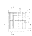
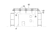
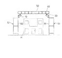
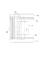
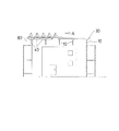
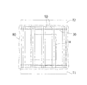
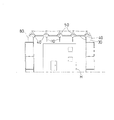
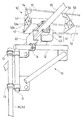
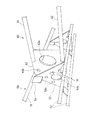
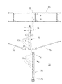
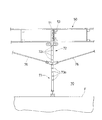
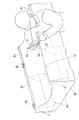
図1乃至図16は本発明の一実施形態を示す図で、図1は実施例の仮設テントの平面図、図2及び図3は実施例の仮設テントの断面図(図2は図1のA−A断面図、図3は図1のB−B断面図)、図4乃至図7は実施例のシートの張設方法を示す説明図、図8は仮設足場にレール、ローラー架台、ガーターを取り付けた状態を示す斜視図、図9は実施例のガーターパーツの接合方法を示す説明図、図10はガーターとつなぎ材の接合部を示す斜視図、図11及び図12は実施例のガーターのレベルを合わせるための束部材を示す説明図、図13は実施例のシートがガーターの上から固定された状態を示す説明図である。
また、図14はシートの固定状態を解除するときに使用する取り外し治具を示す説明図、図15は取り外し治具を用いてクリップを外す手順を示す説明図、図16は実施例の仮設テントのシートに設けられたドレーンの配置を示す説明図、である。
1 to 16 are views showing an embodiment of the present invention. FIG. 1 is a plan view of a temporary tent according to the embodiment. FIGS. 2 and 3 are cross-sectional views of the temporary tent according to the embodiment. AA sectional view, FIG. 3 is a sectional view taken along the line BB of FIG. 1, FIGS. 4 to 7 are explanatory views showing a method of stretching the seat of the embodiment, and FIG. 8 is a temporary scaffold with rails, roller mounts, garters FIG. 9 is an explanatory view showing a method for joining garter parts according to the embodiment, FIG. 10 is a perspective view showing a joint portion between the garter and the connecting material, and FIGS. 11 and 12 are garters according to the embodiment. FIG. 13 is an explanatory view showing a state in which the sheet of the embodiment is fixed from above the garter.
14 is an explanatory view showing a removal jig used to release the fixed state of the sheet, FIG. 15 is an explanatory view showing a procedure for removing the clip using the removal jig, and FIG. 16 is a temporary tent of the embodiment. It is explanatory drawing which shows arrangement | positioning of the drain provided in the sheet | seat of this.
(仮設テント及び仮設テント用梁部材の構成)
本実施形態の仮設テントSは、仮設足場Tに支持されるブラケット10に固定されるレール支持材20と、該レール支持材20に固定されるレール30と、該レール30に装着されるローラー架台40と、該ローラー架台40の上面に取り付けられるガーター50と、隣接するガーター50同士を所定間隔で連結するつなぎ材60と、前記ガーター50に着脱可能な束部材70と、前記ガーター50及びつなぎ材60の上に張設されるシート80と、該シート80に設けられた排水用のドレーン90と、を有して構成されている。
なお、上述のレール30が本発明のレール部材に相当し、ガーター50が本発明の梁部材に相当し、シート80が本発明のシート部材に相当する。
(Configuration of temporary tent and beam member for temporary tent)
The temporary tent S of the present embodiment includes a
The
仮設テントSは、図1に示すように、建物Hを挟んで対向する位置に設けられた仮設足場T1及びT2によって支持されている。なお、図1乃至図3においてシート80は図示を省略している。また、図1において、図2及び図3に示されているブラケット10、ローラー架台40は図示を省略している。
As shown in FIG. 1, the temporary tent S is supported by temporary scaffolds T <b> 1 and T <b> 2 provided at positions facing each other across the building H. 1 to 3, the
図3に示すように、この仮設足場T1及びT2の内側(建物側)の縦枠材R1及びR2の上端部には、ブラケット10が各々略同一高さに取り付けられている。ブラケット10は、図8に示すように、縦フレーム材11と、縦フレーム材11に固定された略水平な横フレーム材12と、を有して構成されている。縦フレーム材11と縦枠材R1,R2とは単管連結材13によって固定され、横フレーム材12は縦フレーム材11の上端から建物側に向けて延出されている。各々の横フレーム材12の上側には、図8に示すように、断面コの字型のレール支持材20の片方のフランジ面が単管クランプ14を介して固定されている。そして、レール支持材20のもう一方のフランジ部の先端にはレール30が固定されている。
As shown in FIG. 3,
レール30は、上述のように、略直線上に並んだ複数の縦枠材R1に、ブラケット1及びレール支持材20を介して複数箇所で支持され、略水平に保持されている。同様に、別のレール30が、略直線上に並んだ複数の縦枠材R2に、ブラケット1及びレール支持材20を介して複数箇所で支持され、略水平に保持されている。つまり、仮設足場T1、T2からそれぞれ建物側にレール30が架設されおり、建物Hを挟んで略平行に2本のレール30が架設されている。なお、本実施形態では、レール30は、2.3mm厚の鋼材からなる直径48.6mmのメッキ鋼管が使用されている。
As described above, the
ローラー架台40は、図8に示すように、走行部41の上に架台部42が接合されている。走行部41は、リップ溝形鋼の断面形状を有するローラー受け材43の内部に、複数のローラー44をコの字型に配設して形成されている。架台部42には、後述するガーター50の下端面の部材が接合される。
このローラー架台40は、略コの字型に配設された各々回転自在なローラー44で囲まれる空間にレール30が挿通されて装着される。このように装着すると、レール30が該ローラー44の回転面に3方向から当接されて支持され、ローラー架台40がレール30に沿って走行自在とされる。また、ローラー44はローラー受け材43の長さ方向に沿って複数配置されているので、レール30に対してローラー受け材43が平行に装着される。
As shown in FIG. 8, the
The
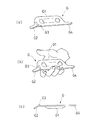
ガーター50は、建物Hを挟んで略平行に架設される一対のレール30,30に架け渡される部材であり、1本の上弦材51及び2本の下弦材52,52を略正三角形の薄板状の梁用プレート53の各々の頂点に接合して構成されている。ガーター50は、両端部が各々ローラー架台40の架台部42に取り付けられている。そして、ガーター50は、両端のローラー架台40,40が略平行なレール30,30に各々装着されることにより、建物上空を走行自在とされる。なお、本実施形態では図6のようなローラー架台40を用いてガーター50を走行自在に構成したが、このような形状に限定されず、レール30に対して走行自在な構成であれば、どのような構成であってもよい。
The
上弦材51及び下弦材52,52は、いずれも1.6mm厚の鋼材からなるメッキ鋼管が使用されている。その径寸法は19.1mmとされている。
梁用プレート53は、3.2mm厚の鋼板からなり、略正三角形の底辺から頂点までの寸法が200mmとされている。なお、この梁用プレート53が、本発明の連結材に相当する。また、この梁用プレート53は、ガーター50の長さ方向に455mm間隔に配置されている。すなわち、モジュール寸法(910mm)の半分のピッチで配置されている。また、梁用プレート53のプレート面はガーター50の長さ方向に対して略垂直とされている。
Each of the
The
梁用プレート53と上弦材51または下弦材52,52は、各々補強プレート54を介して接合されている。この補強プレート54は、約50mm角の3.2mm厚の鋼板であって、一端面が梁用プレート53のプレート面に溶接され、該溶接面と隣り合う端面が上弦材51または下弦材52,52の側面に溶接されている。
また、梁用プレート53には、その略中央に直径50mmの円形開口53aが設けられており、部材の軽量化が図られている。また、この円形開口53aの周囲に複数の直径13mmのボルト接合穴53bが設けられている。ボルト接合穴53bのうち3個は、円形開口53aの中心から三角形の各頂点に向かって60mm離間した位置を中心として設けられている。また、別のボルト接合穴53bは、円形開口53aの中心から三角形の各辺に向かう垂線上であって、各辺から25mm内側の位置を中心として設けられている。
The
Further, the
本実施形態では、長尺部材のガーター50を人力で架設するために、互いに着脱可能な複数のガーターパーツ55が長さ方向に連結されたガーターを作業床上で組み立てて架設している。各々のガーターパーツ55は、その最大長さが3640mmとされ、その最大重量が11kgとされている。なお、このガーターパーツ55が、本発明の組立部材に相当する。
これらの部材の運搬に際し、各々の部材を作業者が手で持つときに苦痛を感じないようにするためには、各々の部材の重量を10kgとする必要があるとされている。すなわち、10kgが作業者に苦痛を感じさせないためのガイドラインの値である。本実施形態のガーターパーツ55は最大重量が11kgとされており、このガイドラインの重量を越えているが、その超過量はわずかである。従って、作業者が本実施形態のガーターパーツ55を運搬しても、それほど作業に苦痛を感じることがない。また、3640mmよりも短いガーターパーツは10kg以下とされており、運搬に際して作業者に苦痛を感じさせることがない。
In this embodiment, in order to construct the
In transporting these members, it is said that the weight of each member needs to be 10 kg so that the operator does not feel pain when holding the member by hand. That is, 10 kg is a guideline value for preventing the worker from feeling pain. The
このように、仮設テントSの構成部材を、全て人力で作業床上へ運搬することができ、かつ作業床上で組立または解体が可能な部材で構成することによって、重機を用いずに梁部材を架け渡すことができ、仮設テントの設置・解体を行うことができる。従って、コストが削減される。また、重機の設置スペースが確保できない現場でも仮設テントを設置することができる。 As described above, the structural members of the temporary tent S can be transported to the work floor by human power and can be assembled or dismantled on the work floor. It can be handed over, and temporary tents can be installed and dismantled. Therefore, the cost is reduced. Temporary tents can also be installed at sites where heavy equipment installation space cannot be secured.
本実施形態の仮設テントは、建物または敷地の大きさによって大きさが異なるものとされる。このような場合に対応するため、ガーターパーツ55として複数種類の長さのものが準備されていると好適である。これにより、様々な長さのガーターを容易に組み立てることができる。例えば、単位モジュール寸法を基準として、その整数倍または整数分の1のガーターパーツを準備する。本実施形態では、建物のモジュール寸法が910mmとされており、その2分の1の455mmを基準に寸法展開されているので、455mmを基準寸法として、この整数倍の寸法展開でガーターパーツを準備する。このようにすると、モジュール展開された建物に対応した寸法のガーターを容易に組み立てることができる。但し、本実施形態では、上述のように作業性及び設置・解体の容易性を考慮して、ガーターパーツの最大長さはモジュール寸法の4倍の3640mmとされる。
また、ガーターの両端は上述した架台部42に固定されるため、ガーターの両端に使用する組立部材として、固定しろを考慮した端部専用の長さのものを準備してもよい。
The temporary tent of the present embodiment varies in size depending on the size of the building or site. In order to cope with such a case, it is preferable that a plurality of types of
In addition, since both ends of the garter are fixed to the above-described
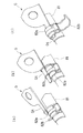
図9に、ガーターパーツ55の接合方法を示す。各々のガーターパーツ55の両端には梁用プレート53が取り付けられており、この梁用プレート53を接合相手のガーターパーツ55端部の梁用プレート53と重ね合わせる。それと共に、上弦材51及び下弦材52,52の端部の開口を接合相手の部材の対応する上弦材、下弦材の開口に対向させる。そして、所定長さの棒状のピン部材Pの両端を、それぞれ対向する開口に挿入し、ピン部材Pを、矢印に示すように、両側から鋼管の内部に収納する。このようにすると、ピン部材Pを介して上弦材51、下弦材52が直線状に連結される。
FIG. 9 shows a method for joining the
このピン部材Pの略中央には、少なくとも1つの突起Qが形成されている。突起Qが形成されていると、その端部から鋼管の内部に差し込まれたピン部材Pは、突起Qの位置以上に深く鋼管の内部に挿入されることはない。従って、必ずピン部材Pの略中央部がガーターパーツ55の連結面、すなわち鋼管と対向する鋼管との境界面に位置されるようにピン部材が保持され、位置ずれを起こすことがない。
At least one protrusion Q is formed in the approximate center of the pin member P. When the protrusion Q is formed, the pin member P inserted into the steel pipe from the end thereof is not inserted deeper than the position of the protrusion Q into the steel pipe. Therefore, the pin member is always held so that the substantially central portion of the pin member P is positioned on the connecting surface of the
そして、重ね合わせた梁用プレート53のボルト接合穴53bにボルトMを挿通してナットNを締め付け、梁用プレート53同士を固定する。図9では一箇所しかボルトが締め付けられていないが、ボルトMは、十分な接合強度を得られる数であれば良く、全てのボルト接合穴53bに取り付けても良いし、一部のボルト接合穴53bのみに取り付けても良い。また、ボルト以外にも、着脱可能な締結材であれば使用することができる。
Then, the bolt M is inserted into the bolt
つなぎ材60は、図1に示すように、隣り合うガーター50の各々の略中央部に連結されている。このつなぎ材60は、隣り合うガーター同士を所定の間隔に保持すると共に、シート80で被覆されたとき、仮設テントの内側からシート80を支持するものである。このようなつなぎ材60を設けた理由については、後述する。
As shown in FIG. 1, the connecting
図10に、つなぎ材60とガーター50との接合部を示す。本実施形態のつなぎ材60は、上弦材61と下弦材62とを矩形のつなぎプレート63で連結して平面的なフレーム状に構成されている。つなぎ用プレート63は、少なくともつなぎ材60の両端部に設けられ、その所定位置に開口63a及びボルト接合穴63bが設けられている。従って、つなぎ材60をガーター50に接合するには、ガーター50の梁用プレート53と、つなぎ材60のつなぎ用プレート63とを重ね合わせる。そして、ボルト接合穴53b、63bにボルトMを挿通してナットNを取り付け、固定すればよい。
In FIG. 10, the junction part of the
束部材70は、ガーター50に接合されてレベル調整を行う際に使用される部材である。この束部材70は、ガーター用束72と、レベル調整束73とを備え、ガーター用束72の胴部に100mm間隔で形成された長さ調整穴72aと、レベル調整束73の胴部に100mm間隔で形成された長さ調整穴73aとを位置合わせしてボルトを挿通して固定することにより、所望の長さに調整することができる。
The
束用プレート71はガーター用束72の先端に固定されており、梁用プレート53と略同一形状とされている。従って、束部材70とガーター50とを接合するには、梁用プレート53と束用プレート71とを重ねてボルトで接合する。また、レベル調整束73は、その下端内部に接合された不図示の長ナット74に螺合された位置調整ネジ75をまわして長さ方向に前進または後退させることにより、レベルの微調整を行うことができる。
図11はガーター用束72、レベル調整束73、及びガーター50の接合方法を説明する分解斜視図である。また、図12は作業床上に組み立てられた束部材70を示す説明図である。なお、レベル調整の手順については、仮設テント及び仮設テント用梁部材の設置方法の欄で後述する。
The
FIG. 11 is an exploded perspective view for explaining a method of joining the
シート80は、ガーター50及びつなぎ材60によって支持されており、ガーター50及びつなぎ材60を覆うように被せられ、ガーター50の上弦材51に対して固定されている。本実施形態のシート80は、公知の防水シートが使用されている。シート80には、ガーター50に対して固定される位置にあらかじめ合わせマークが印刷されている。また、上弦材51と当接する取付部分にはあらかじめ増し張りが施され、補強が施されている。
The
後述するように、本実施形態のシート80の張設方法では、複数本のガーター50をレール上の一箇所に寄せ集め、ガーター50と隣り合うガーター50とが近接した状態で、ガーター間にシート80がたるんだ状態となるように取り付ける。そして、ガーター50を移動させてシート80を展伸させ、ガーター50が所定位置まで移動されたときに、シート80が略水平に緊張されるように構成されている。そのため、本実施形態の合わせマークは、シート80を緊張した状態における隣合うガーター50間の距離に、シートを上弦材51に固定するための固定しろを加えた間隔で印刷されている。
このような合わせマークが印刷されていると、合わせマークを基準に、たるんだ状態でシート80をガーター50に固定しておき、その後シート80を展伸したときには、シート80がちょうど略水平に緊張されるようにすることができる。従って、取り付け時にその都度シートのどの位置で固定すればよいか測って取り付ける必要がなく、取付作業が簡易化される。また、正確な位置で固定することができ、展伸されたシートが略水平に緊張されるようにすることができる。
As will be described later, in the method for stretching the
When such an alignment mark is printed, the
本実施形態の合わせマークは、シート80の両側縁に所定間隔で印刷されており、この合わせマークをガーター50の上弦材の両端部に合わせてシートを固定すればよいが、合わせマークの位置はこのような位置に限定されず、シート80の固定位置を定められる位置であれば、どのような位置に印刷してもよい。また、シート80の両側縁だけでなく、シート80の内部側にも印刷しておき、ガーター50の長さ方向の中間部に固定される内部側の固定位置についても、正確に位置決めできるようにしておいてもよい。
また、合わせマークは印刷によるものに限定されず、合わせ位置が認識できるものであればどのようなものでもよい。例えば、所定の位置決め部材を取り付けておく方法でもよい。
The alignment marks of the present embodiment are printed on both side edges of the
The alignment mark is not limited to printing, and any alignment mark can be used as long as the alignment position can be recognized. For example, a method of attaching a predetermined positioning member may be used.
図13に実施例のシート80がガーター50の上から被せられて一部が固定された状態を示す。この図において、シート80に覆われたガーターの形状を点線で示す。シート80を上弦材51に対して固定する方法は、以下のようなものである。シート80を被せた上から、所定長さの略C字型断面を有するチューブ材81を上弦材51に嵌着する。これにより、上弦材51とチューブ材81との間でシート80が挟持され、固定される。そして、チューブ材81の両端部等のはずれ易い箇所には、さらにチューブ材81の外側からクリップ82を嵌着して、より強固に固定する。
FIG. 13 shows a state in which the
チューブ材81及びクリップ82は着脱可能な挟持部材である。チューブ材81は弾力性のある樹脂製品からなり、C字型断面の開口部分を拡げてシート80及び上弦材を押し込み、挟み込むことができる。クリップ82は、C字型断面の短い筒材82aの外側からバネ材82bで挟み込むものであって、バネ材82bを筒材82aの一端に軸支させ、回動させることによって、挟み込みまたは取り外しできるものである。
なお、シート80の固定状態を解除する手順及び解除の際に使用される取り外し治具Gについては、後述する。
The
The procedure for releasing the fixed state of the
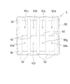
次に、つなぎ材60を設けた理由について説明する。図16に仮設テントSの平面図を示す。この図において、シート80に被覆されたガーター50、レール30、つなぎ材60、は点線で示されており、仮設足場T及び建物Hは図示を省略している。図16に図示されるように、シート80には、仮設テントSの外側と内側とを連通するドレーン90a乃至90hが設けられている。そして、このドレーン90a乃至90hには、各々仮設テントSの内側に連通する不図示の排水ホース91a乃至91hが接続されている。排水ホースは、排水の必要がないときには取外して建築工事の邪魔にならないようにすることもできる。そして、排水ホースを取り外したときには、ドレーン90a乃至90hには防水キャップ等を嵌着してふさいでおくこともできる。
Next, the reason for providing the connecting
シート80の上に雨水が溜まると、溜まった雨水がこのドレーン90にうまく流入されれば、排水ホース91によってテント外へ排出することができる。本実施形態の仮設テントSでは、上述したようにガーター50の上弦材51にシート80が固定されて支持されているので、上弦材51を境にガーター50の両側に雨水が振り分けられる。同様に、つなぎ材60の両側に雨水が振り分けられる。つまり、つなぎ材60を設けることにより、隣り合うガーター50、つなぎ材60、及びレール30によって囲まれる矩形の構面が一つの排水負担領域となり、排水負担領域が2分割される。そして、これらのつなぎ材60を境に隣り合う排水負担領域は、排水系統が別となる。
When rainwater accumulates on the
本願出願人は、まず、つなぎ材60を設けない構成で仮設テントの試作実験を行った。このとき、ドレーンの位置は図16と同様に設けられていた。すなわち、隣り合うガーター50及び一対のレール30で囲まれる構面に各々2ヶ所のドレーン90が設けられていた。また、この配置以外の配置でも、試験を行った。その結果、つなぎ材を設けない構成では、雨水が必ずしもドレーン90に流入されず、排水を確実に行うことができないことを知った。
つまり、実験の結果によれば、つなぎ60が設けられていない状態、すなわち排水負担領域が広い場合には、排水負担領域内に局部的な水たまりが形成された。このような水たまりは、その発生位置が一定とされていなかった。そして、いったんそのような水たまりが形成されると、そこに溜まった雨水は、作業者がドレーンの位置に移動させて排水させない限り、いつまでも排水されない。このように、雨水が集中した部分のシート80及びシート80を支持する部材の負担が増大し、仮設テントSの耐久性に悪影響を与える。また、建築工事の作業性に悪影響を与える。
The applicant of the present application first conducted a trial experiment of a temporary tent in a configuration in which the connecting
That is, according to the result of the experiment, when the
そこで、本願出願人は、工夫を重ねた結果、つなぎ材60で隣り合うガーター50の中央部分を連結して排水負担領域を2分割し、つなぎ材を境として両側に雨水が振り分けられるようにした。そして、図16のように、排水負担領域、すなわち、隣り合うガーター50、つなぎ材60、及びレール30によって囲まれる矩形の構面の対角線の交点に各々のドレーン90a乃至90hを位置させるようにした。このようにすると、局部的に水たまりができる等の排水不良が発生せず、各々のドレーン90a乃至90hから良好に排水されることを知った。
Therefore, as a result of repeated efforts, the applicant of the present application connected the central portions of the
(仮設テント及び仮設テント用梁部材の設置方法)
以下、本実施形態の仮設テントSを設置する手順について説明する。
(1)まず、ブラケット10及び仮設テントSの構成部材を仮設足場T又は建物Hの作業床上に運び上げる。構成部材としては、レール支持材20、レール30、ローラー架台40、ガーターパーツ55、つなぎ材60、ガーター用束72、レベル調整束73、シート80、排水ホース91、シート取付具(チューブ材81、クリップ82)等がある。また、必要工具及び連結用の部材を運び上げる。
(Installation method of temporary tent and beam member for temporary tent)
Hereinafter, a procedure for installing the temporary tent S of the present embodiment will be described.
(1) First, the structural members of the
(2)次に、レールを設置する。すなわち、仮設足場Tの縦枠材Rにブラケット10を固定し、レール30をレール支持材20を介してブラケット10の上に固定する。
(3)次に、ガーターパーツを組み立てる。すなわち、ガーターパーツ55の端部の梁用プレート53同士を連結して所定の寸法及び数量のガーター50を組み立てる。そして、ガーター50の両端にローラー架台40を取り付ける。
(4)次に、ガーターをレール間に架け渡す。すなわち、各々のローラー架台40をレール30に取り付けてガーター50を所望の数だけ架け渡す。
(2) Next, a rail is installed. That is, the
(3) Next, assemble the garter parts. That is, the
(4) Next, the garter is bridged between the rails. That is, each
(5)次に、ガーター50にシート80を張設する。まず、全てのガーター50をレール上で一箇所に寄せ集めて、シート80で覆う。そして、予めシートに印刷された合わせマークの位置を各々のガーター50の上弦材51の位置とを合わせてシートをガーター50の上弦材51に固定する。このとき、ガーター50が寄せ集められているので、シート80はガーター50の間にたるんだ状態とされている。図4及び図5がこの状態の仮設テントSを示す。その後、シート80と全てのガーター50との固定作業が終了した後、ガーター50を図4及び図5のA方向にスライドさせて、蛇腹状に配設されていたシート80を展伸させ、ぴんと緊張させる。図6及び図7がこの状態の仮設テントSを示す。
(5) Next, the
(6)次に、シート80が緊張された状態で、各々のローラー架台40をレール30に対して固定する。仮設テントSの構成の欄では説明を省略したが、ローラー架台には、レール30の真上に位置される部位に、上方から棒状の固定ピンを挿通させることが可能な穴が形成されている。また、レール30には、この固定ピンを挿通させることが可能な固定穴が所定間隔で形成されている。この固定穴を、シートの合わせマークの間隔と対応させて設けておくことにより、シート80が展伸され、略水平に張設された状態でローラー架台40とレールとを1本の固定ピンで挿通させ、動かないようにすることができる。この方法では、予めレール30に固定穴が形成されているので位置決めが容易となるが、これ以外にも、公知のクランプ等を用いて所望の位置にローラー架台40を固定するようにしてもよい。
(6) Next, in a state where the
(7)次に、各々のガーター50の中間部に束部材70を接合してレベル合わせを行う。図11及び図12に示すように、ガーター用束72の一端に固定された束用プレート71とガーター50の梁用プレート53とをボルトで接合する。そして、ガーター50のレベルが最も設計位置に近くなるように、長さ調整穴72aと長さ調整穴73aとを位置合わせしてボルトを挿通し、ガーター用束72とレベル調整束73を接合する。そして、このレベル調整束73を、シート80によって覆われた建物の屋上又は作業床、あるいは仮設足場の作業床、等の上(図12においてFとして示す)に設置する。このように、おおよそのレベルを合わせた後、レベル調整束73の下端に設けた位置調整ネジ75により、レベルの微調整を行う。
(7) Next, the
(8)そして、レベル微調整を行った後、ガーター用束の下端とガーター50の両端のローラー架台4とを、各々ブレース材76によって接合し、張力を与える。これによりガーター50のたわみが改善され、ガーター50が略直線状態に保持される。
(9)次に、隣り合うガーター50の中間部をつなぎ材60で連結する。
(10)最後に、排水ホース91をドレーン90に接続して排水路を確保する。
(8) Then, after performing level fine adjustment, the lower ends of the garter bundle and the roller mounts 4 at both ends of the
(9) Next, the intermediate portions of the
(10) Finally, the drainage hose 91 is connected to the drain 90 to secure a drainage channel.
(シートの固定解除方法)
本実施形態の仮設テントを解体するときにシート80の固定を解除する方法について説明する。
図13では、作業者がシート80の一部の固定状態を途中まで解除した状態を示しているが、シートの固定状態を解除するには、まずクリップ82を取り外し、その後、チューブ材81を取り外す。このとき、作業者は、取り外し治具Gを使用して作業を行う。
図14に取り外し治具Gの斜視図及び側面図を示す。この取り外し治具Gは、片手で握るのに丁度良い寸法の握り部G1と、その一端から所定角度で突出する突起部G2と、突起部G2の根元に形成された隆起部G3と、突起部G2と逆の端部に握り部G1と同一平面上に突出する突起部G4と、を備えている。作業者は、この突起部G2をチューブ材81とシート80との隙間に差し込み、てこの原理を用いて隆起部G3を基点として突起部G2を回動させ、チューブ材81をシート80及び上弦材51からひきはがす。
(How to unlock the sheet)
A method for releasing the fixation of the
FIG. 13 shows a state in which the worker has partially released the fixed state of the
FIG. 14 shows a perspective view and a side view of the removal jig G. FIG. The removal jig G includes a grip portion G1 having a size that is just right for gripping with one hand, a projection portion G2 that projects from one end thereof at a predetermined angle, a raised portion G3 formed at the base of the projection portion G2, and a projection portion. A protrusion G4 protruding on the same plane as the grip portion G1 is provided at the end opposite to G2. The operator inserts the protruding portion G2 into the gap between the
また、図15にクリップ82を外すときの手順を示す。まず、図15(a)に示すように、バネ材82bと筒材82aとの隙間に突起部G4を差し込む。次に、図15(b)に示すように、突起部G4をその延出方向を軸として回動させ、バネ材82bと筒材82aとの隙間を広げ、バネ材82bを回動させる。図15(c)に示すように、筒材82aとチューブ材81との隙間に突起部G4を差し込み、同様に突起部G4を回動させて筒材82aをチューブ材81からひきはがす。
FIG. 15 shows a procedure for removing the
10 ブラケット、11 縦フレーム材、12 横フレーム材、13 単管連結材、14 単管クランプ、20 レール支持材、30 レール、40 ローラー架台、41 走行部、42 架台部、43 ローラー受け材、44 ローラー、50 ガーター、51 上弦材、52 下弦材、53 梁用プレート、53a 円形開口、53b ボルト接合穴、54 補強プレート、55 ガーターパーツ、60 つなぎ材、61 上弦材、62 下弦材、63 つなぎ用プレート、63a 開口、63b ボルト接合穴、70 束部材、71 束用プレート、72 ガーター用束、72a 長さ調整穴、73 レベル調整束、73a 長さ調整穴、74 長ナット、75 位置調整ネジ、76 ブレース材、80 シート、81 チューブ材、82 クリップ、82a 筒材、82b バネ材、90,90a乃至90h ドレーン、91,91a乃至91h 排水ホース、G 治具、G1 握り部、G2 突起部、G3 隆起部、G4 突起部、F 作業床、H 建物、M ボルト、N ナット、P ピン部材、Q 突起、R,R1,R2 縦枠材、S 仮設テント、T,T1,T2 仮設足場
DESCRIPTION OF
Claims (7)
建物又は敷地の周囲に設置された仮設足場に略水平に架設される一対の略平行なレール部材と、
該レール部材の各々に両端が支持されて建物又は敷地の上空に架け渡され、前記レール部材に沿って走行自在に構成された複数の梁部材と、
隣り合う梁部材の間に張設されるシート部材と、を備え、
前記梁部材の各々は、互に着脱可能な組立部材を長さ方向に連結して構成されていることを特徴とする、仮設テント。 A temporary tent covering the top of the building or site,
A pair of substantially parallel rail members installed substantially horizontally on a temporary scaffold installed around the building or site;
A plurality of beam members that are supported on both ends of each of the rail members and spanned over the building or site, and are configured to be able to travel along the rail members;
A sheet member stretched between adjacent beam members,
Each of the beam members is formed by connecting assembly members that are detachable from each other in the length direction, and is a temporary tent.
前記連結材は、薄板状のプレートからなり、少なくとも前記組立部材の両端に配設されると共に、他の組立部材の端部に配設された連結材と着脱可能に構成されることを特徴とする、請求項1に記載の仮設テント。 The assembly member includes at least one upper chord member, at least two lower chord members, and a connecting member joined to the upper chord member and the lower chord member,
The connecting material is formed of a thin plate-like plate, and is arranged at least at both ends of the assembly member, and is configured to be detachable from a connection material arranged at an end of another assembly member. The temporary tent according to claim 1.
前記上弦材及び前記下弦材は略同一断面形状の管状部材からなることを特徴とする、請求項2及び請求項3に記載の仮設テント。 The shape of the plate surface of the connecting material is a substantially equilateral triangle, and either the upper chord material or the lower chord material is joined to each apex portion, and an opening is provided at the approximate center of the plate surface of the connecting material. Provided,
The temporary tent according to claim 2 and 3, wherein the upper chord member and the lower chord member are formed of tubular members having substantially the same cross-sectional shape.
互に着脱可能な組立部材を長さ方向に連結して構成され、
前記組立部材は、少なくとも1本の上弦材と、少なくとも2本の下弦材と、前記上弦材及び下弦材に接合された連結材と、を有し、
前記連結材は、薄板状のプレートからなり、少なくとも前記組立部材の両端に配設されると共に、他の組立部材の端部に配設された連結材と着脱可能に構成されることを特徴とする、仮設テント用梁部材。 A beam member that supports a sheet member of a temporary tent that covers the top of a building or site,
It is constructed by connecting assembly members that can be attached to and detached from each other in the length direction,
The assembly member includes at least one upper chord member, at least two lower chord members, and a connecting member joined to the upper chord member and the lower chord member,
The connecting material is formed of a thin plate-like plate, and is arranged at least at both ends of the assembly member, and is configured to be detachable from a connection material arranged at an end of another assembly member. A beam member for a temporary tent.
前記上弦材及び前記下弦材は略同一断面形状の管状部材からなることを特徴とする、請求項5及び請求項6に記載の仮設テント用梁部材。 The shape of the plate surface of the connecting material is a substantially equilateral triangle, and either the upper chord material or the lower chord material is joined to each apex portion, and an opening is provided at the approximate center of the plate surface of the connecting material. Provided,
The beam member for a temporary tent according to claim 5 or 6, wherein the upper chord member and the lower chord member are formed of tubular members having substantially the same cross-sectional shape.
Priority Applications (1)
| Application Number | Priority Date | Filing Date | Title |
|---|---|---|---|
| JP2004106008A JP2005290780A (en) | 2004-03-31 | 2004-03-31 | Temporary tent and beam member therefor |
Applications Claiming Priority (1)
| Application Number | Priority Date | Filing Date | Title |
|---|---|---|---|
| JP2004106008A JP2005290780A (en) | 2004-03-31 | 2004-03-31 | Temporary tent and beam member therefor |
Publications (1)
| Publication Number | Publication Date |
|---|---|
| JP2005290780A true JP2005290780A (en) | 2005-10-20 |
Family
ID=35324029
Family Applications (1)
| Application Number | Title | Priority Date | Filing Date |
|---|---|---|---|
| JP2004106008A Pending JP2005290780A (en) | 2004-03-31 | 2004-03-31 | Temporary tent and beam member therefor |
Country Status (1)
| Country | Link |
|---|---|
| JP (1) | JP2005290780A (en) |
Cited By (2)
| Publication number | Priority date | Publication date | Assignee | Title |
|---|---|---|---|---|
| JP2008115560A (en) * | 2006-11-01 | 2008-05-22 | Miuragumi:Kk | Temporary roof structure |
| KR102143209B1 (en) * | 2020-02-17 | 2020-08-11 | 최운성 | Temporary roofing equipment for building construction |
-
2004
- 2004-03-31 JP JP2004106008A patent/JP2005290780A/en active Pending
Cited By (2)
| Publication number | Priority date | Publication date | Assignee | Title |
|---|---|---|---|---|
| JP2008115560A (en) * | 2006-11-01 | 2008-05-22 | Miuragumi:Kk | Temporary roof structure |
| KR102143209B1 (en) * | 2020-02-17 | 2020-08-11 | 최운성 | Temporary roofing equipment for building construction |
Similar Documents
| Publication | Publication Date | Title |
|---|---|---|
| AU668760B2 (en) | Form panel | |
| KR101904832B1 (en) | The method for installing tents for building construction | |
| KR101928301B1 (en) | The device for installing tents for building construction | |
| US3999336A (en) | Building dome structure | |
| JP6942680B2 (en) | Construction method of temporary bridge | |
| JP2005290780A (en) | Temporary tent and beam member therefor | |
| JP2005290781A (en) | Temporary tent | |
| KR100300649B1 (en) | Modular Roof Structure | |
| JP3076202U (en) | Prop bracket attachment for folded roofs | |
| JP6300563B2 (en) | Waterproof board | |
| JP2005290782A (en) | Detaching fixture | |
| JPH10109176A (en) | Temporary rainproof windbreak equipment for steel column welding | |
| JP3640194B2 (en) | Roof structure of large-scale building structure and roof construction method | |
| JPH0372165A (en) | Lifting fixture | |
| CN120592398B (en) | A steel truss floor deck installation structure and method | |
| JP2600489Y2 (en) | Temporary roof for construction work | |
| JP2612435B2 (en) | Overhead crane | |
| JP2000045228A (en) | Casing structure for construction joint part | |
| JP2002322760A (en) | Fixing part structure of membrane member, fixing method, and shape steel for membrane member fixation using therefor | |
| JPH102132A (en) | Method for simultaneously stretching double film | |
| JPH05195633A (en) | Temporary roof and construction method thereof | |
| JPH09215451A (en) | Portable greenhouse film spreading machine and greenhouse film spreading method using the same | |
| JP7527030B2 (en) | Bracket and roof structure | |
| JP6968410B2 (en) | Connecting bracket | |
| JP2008115560A (en) | Temporary roof structure |
Legal Events
| Date | Code | Title | Description |
|---|---|---|---|
| A621 | Written request for application examination |
Free format text: JAPANESE INTERMEDIATE CODE: A621 Effective date: 20070314 |
|
| A977 | Report on retrieval |
Effective date: 20091030 Free format text: JAPANESE INTERMEDIATE CODE: A971007 |
|
| A131 | Notification of reasons for refusal |
Effective date: 20091110 Free format text: JAPANESE INTERMEDIATE CODE: A131 |
|
| A02 | Decision of refusal |
Free format text: JAPANESE INTERMEDIATE CODE: A02 Effective date: 20100309 |