JP2005290735A - Folding door device with handle - Google Patents

Folding door device with handle Download PDF

Info

Publication number
JP2005290735A
JP2005290735A JP2004104728A JP2004104728A JP2005290735A JP 2005290735 A JP2005290735 A JP 2005290735A JP 2004104728 A JP2004104728 A JP 2004104728A JP 2004104728 A JP2004104728 A JP 2004104728A JP 2005290735 A JP2005290735 A JP 2005290735A
Authority
JP
Japan
Prior art keywords
folding door
handle
panel
panel body
opening
Prior art date
Legal status (The legal status is an assumption and is not a legal conclusion. Google has not performed a legal analysis and makes no representation as to the accuracy of the status listed.)
Withdrawn
Application number
JP2004104728A
Other languages
Japanese (ja)
Inventor
Akira Nishida
明 西田
Current Assignee (The listed assignees may be inaccurate. Google has not performed a legal analysis and makes no representation or warranty as to the accuracy of the list.)
Itoki Corp
Original Assignee
Itoki Corp
Priority date (The priority date is an assumption and is not a legal conclusion. Google has not performed a legal analysis and makes no representation as to the accuracy of the date listed.)
Filing date
Publication date
Application filed by Itoki Corp filed Critical Itoki Corp
Priority to JP2004104728A priority Critical patent/JP2005290735A/en
Publication of JP2005290735A publication Critical patent/JP2005290735A/en
Withdrawn legal-status Critical Current

Links

Images

Landscapes

  • Extensible Doors And Revolving Doors (AREA)

Abstract

【課題】 間仕切壁の一部にドアとしてあるいはキャビネット等の収納庫の開閉扉として用いることができ、二枚のパネル体を屈曲可能に連結するリンク機構が簡単で安価に構成できるとともに、パネル体の開閉軌跡が安定で、ガタツキのない開閉を実現することができ、しかも二枚のパネル体の連接部に引手を設けても指を挟む心配のない引手付き折戸装置を提供する。
【解決手段】 二枚のパネル体2,3の連接縁6,7同士を近接配置するとともに、該連接縁に沿った方向に1つの回動軸芯8を有するヒンジ4にて互に屈曲可能に連結して折戸1を形成し、該折戸を開放する際に山折れする側であって、一方のパネル体の連接縁に沿って回動軸芯を中心とする半円筒状の第一指掛部9を有する引手5を設けた。
【選択図】 図1
PROBLEM TO BE SOLVED: To provide a simple and inexpensive link mechanism that can be used as a door on a part of a partition wall or as an opening / closing door of a storage such as a cabinet, and to connect two panel bodies in a bendable manner. There is provided a folding door device with a handle that can realize opening and closing with a stable opening and closing locus, and that does not cause rattling even when a handle is provided at the connecting portion of two panel bodies.
SOLUTION: The connecting edges 6 and 7 of two panel bodies 2 and 3 are arranged close to each other and can be bent to each other by a hinge 4 having a single pivot axis 8 in a direction along the connecting edge. The first finger having a semi-cylindrical shape centered on the pivot axis along the connecting edge of one panel body is a side that is folded when the folding door 1 is opened by being connected to A handle 5 having a hook 9 is provided.
[Selection] Figure 1

Description

本発明は、引手付き折戸装置に係わり、更に詳しくは間仕切壁の一部にドアとしてあるいはキャビネット等の収納庫の開閉扉として用いる引手付き折戸装置に関するものである。   The present invention relates to a folding door device with a handle, and more particularly to a folding door device with a handle used as a door in a part of a partition wall or as an opening / closing door of a storage such as a cabinet.

従来から、間仕切壁の一部に設けるドアや、キャビネット等の収納庫の開口部に設ける開閉扉として折戸を用いることは公知である。この折戸は、二枚のパネル体の連接縁同士を近接配置し、その連接縁に沿った方向に回動軸芯を有するヒンジにて互に屈曲可能に連結して構成し、二枚のパネル体が直線状になって開口部を閉止した状態と、略180度回動屈曲して二枚のパネル体が重合状態になって開口部を開放した状態とをとるようになっている。通常、折戸は二枚のパネル体の背面側に前記ヒンジとして蝶番を設けて連結して構成し、両パネル体の連接縁が手前に突出して山折れ屈曲する側に引手を設けているが、折戸の屈曲伸展動作時に両パネル体の両連接縁の隙間が変化し、特に折戸を閉じる際に両連接縁の隙間が小さくなって指を挟む危険性があるので、引手は連接縁から離れた位置に設けることが一般的である。   Conventionally, it is known to use a folding door as a door provided at a part of a partition wall or as an opening / closing door provided at an opening of a storage such as a cabinet. This folding door is constructed by arranging two panel bodies in close proximity to each other and connecting them so that they can be bent with a hinge having a pivot axis in the direction along the connection edge. The body is linear and the opening is closed, and the two panels are turned and bent approximately 180 degrees, and the opening is opened. Usually, folding doors are constructed by connecting hinges as hinges on the back side of the two panel bodies, and the connecting edges of both panel bodies protrude forward and provide handle on the side where they bend and bend, The gap between the connecting edges of both panel bodies changes when the folding door is bent and extended, and especially when closing the folding door, there is a risk that the gap between the connecting edges will be small and the fingers may be caught. Generally, it is provided at a position.

特許文献1には、二枚のパネル体の相対応する側端面に装着した目地板材の一端部にヒンジ金具の両端部を回動可能に連結し、ヒンジ金具で両パネル体の隙間を塞ぎ、各目地板材の端面を傾斜させることにより、パネル体を直線状にしたときに、両目地板材でV字状に開いた空間を形成して指を挟まないようにした折戸装置が記載されている。しかし、この特許文献1の折戸装置は、指を挟まないようにパネル体の連接部に十分に大きな幅のV字溝を設けなければならず、パネル体を直線状にして空間部を閉じた際には、このV字溝が正面に現れて、外観性を損なうことになる。また、ヒンジ金具の両端をそれぞれのパネル体の目地板材に枢着して2点回動軸を有するリンク構造であるので、パネル体の開閉軌跡が不安定になることが容易に推測できる。更に、把手を可動側のパネル体の遊端寄りに設けている構造は、本発明が目的とするところではない。   In Patent Document 1, both ends of a hinge metal fitting are rotatably connected to one end of a joint plate material attached to corresponding side end faces of two panel bodies, and the gap between both panel bodies is closed with the hinge metal fitting, A folding door device is described in which, when the panel body is straightened by inclining the end face of each joint plate material, a space opened in a V shape is formed by both joint plate materials so as not to pinch fingers. . However, the folding door device of Patent Document 1 must be provided with a V-shaped groove having a sufficiently large width at the connecting portion of the panel body so as not to pinch fingers, and the panel body is straightened to close the space portion. At this time, this V-shaped groove appears on the front surface, which impairs the appearance. Further, since the link structure has a two-point pivot shaft with both ends of the hinge fitting pivoted on the joint plate material of each panel body, it can be easily estimated that the opening / closing locus of the panel body becomes unstable. Furthermore, the structure in which the handle is provided near the free end of the movable panel body is not the object of the present invention.

また、特許文献2には、左右一対のパネル体の間に細幅の中間板を配し、中間板の上下端面にそれぞれパネル体の上下端面に対向するように設けられた連結板の両端部を、それぞれパネル体の上下端面に枢軸にて水平揺動自在に連結し、パネル体の中間板側の側面が、枢軸の中心又はその近傍を中心とする円弧面となされており、更に前記中間板の左右端部の前部にパネル体の円弧面に沿う円弧面を有する左右の張出部が設けられ、前記中間板の前面に把手が設けられている構造の折戸装置が開示されている。つまり、二枚のパネル体の連接部に把手を設けた折戸装置が開示されているが、ここに開示された折戸装置は、二枚のパネル体の連接縁間に中間板を有しているので、パネル体の間の目地部に中間板により外形縦線が生じ、特に他の固定パネルと連設する場合には、目地部の統一性がなくなって間仕切壁としての意匠性を損なうことになるばかりでなく、部品点数が増大してコスト高となる。その上、前述のものと同様に、二枚のパネル体が2点回動軸を有するリンク機構で連結されているので、パネル体の開閉軌跡が不安定になる問題を内在している。
特許第3240508号公報 特開平9−125832号公報
Further, in Patent Document 2, a narrow intermediate plate is arranged between a pair of left and right panel bodies, and both end portions of a connecting plate provided on the upper and lower end surfaces of the intermediate plate so as to face the upper and lower end surfaces of the panel body, respectively. Are connected to the upper and lower end surfaces of the panel body so as to be horizontally swingable by pivots, and the side surface on the intermediate plate side of the panel body is an arc surface centered on or near the center of the pivot axis. There is disclosed a folding door device having a structure in which left and right projecting portions having arc surfaces along the arc surface of a panel body are provided in front portions of left and right end portions of a plate, and a handle is provided on the front surface of the intermediate plate. . That is, although the folding door apparatus which provided the handle in the connection part of two panel bodies is disclosed, the folding door apparatus disclosed here has an intermediate | middle board between the connection edges of two panel bodies. As a result, vertical lines are generated by the intermediate plate at the joints between the panel bodies, and in particular when connecting with other fixed panels, the uniformity of the joints is lost and the design as a partition wall is impaired. In addition, the number of parts increases and the cost increases. In addition, similar to the above, since the two panel bodies are connected by a link mechanism having a two-point rotation shaft, there is a problem that the opening / closing locus of the panel body becomes unstable.
Japanese Patent No. 3240508 JP-A-9-125732

そこで、本発明が前述の状況に鑑み、解決しようとするところは、間仕切壁の一部にドアとしてあるいはキャビネット等の収納庫の開閉扉として用いる引手付き折戸装置であって、二枚のパネル体を屈曲可能に連結するリンク機構が簡単で安価に構成できるとともに、パネル体の開閉軌跡が安定で、ガタツキのない開閉を実現することができ、しかも二枚のパネル体の連接部に引手を設けても指を挟む心配のない引手付き折戸装置を提供する点にある。   Therefore, in view of the above-described situation, the present invention intends to solve a folding door device with a handle that is used as a door in a partition wall or as an opening / closing door of a storage such as a cabinet, and includes two panel bodies. The link mechanism that can be bent is simple and inexpensive, the opening and closing locus of the panel body is stable, and it can be opened and closed without any rattling, and a handle is provided at the connecting part of the two panel bodies However, the present invention is to provide a folding door device with a handle that does not have to worry about pinching a finger.

本発明は、前述の課題解決のために、二枚のパネル体の連接縁同士を近接配置するとともに、該連接縁に沿った方向に1つの回動軸芯を有するヒンジにて互に屈曲可能に連結して折戸を形成し、該折戸を開放する際に山折れする側であって、一方のパネル体の連接縁に沿って前記回動軸芯を中心とする半円筒状の第一指掛部を有する引手を設けた引手付き折戸装置を構成した(請求項1)。   In the present invention, in order to solve the above-described problems, the connecting edges of the two panel bodies are arranged close to each other, and can be bent to each other by a hinge having one pivot axis in the direction along the connecting edges. A semi-cylindrical first finger centered on the pivot axis along the connecting edge of one panel body, which is a side that is folded when the folding door is opened. A folding door device with a handle provided with a handle having a hanging portion was constructed (claim 1).

ここで、前記第一指掛部の外面と他方のパネル体の連接縁の端縁との間の隙間を、前記折戸の屈曲伸展動作の全軌跡において、指が入らない略一定の間隔に設定してなることが好ましい(請求項2)。   Here, the gap between the outer surface of the first finger-hanging portion and the edge of the connecting edge of the other panel body is set to a substantially constant interval where the finger does not enter in the entire trajectory of the folding and extending operation of the folding door. (Claim 2).

また、前記ヒンジの回動軸芯を、各パネル体の裏面より後方位置に設定してなるのである(請求項3)。   Further, the pivot axis of the hinge is set at a rear position from the back surface of each panel body (Claim 3).

そして、一方の前記パネル体の連接縁の一部を切欠して指を差し入れる開口部を形成するとともに、該開口部の内奥部に前記第一指掛部を有する引手を取付けてなるのである(請求項4)。   And since it forms the opening part which notches a part of connection edge of one said panel body, and inserts a finger | toe, and the handle which has said 1st finger hook part is attached to the inner back part of this opening part, (Claim 4).

更に、前記第一指掛部と対向する前記パネル体の縁部で、前記開口部の内部に第二指掛部を凹設してなることがより好ましい(請求項5)。   Furthermore, it is more preferable that a second finger hook portion is recessed in the opening at the edge of the panel body facing the first finger hook portion.

以上にしてなる請求項1に係る発明の引手付き折戸装置は、二枚のパネル体の連接縁同士を、1つの回動軸芯を有するヒンジにて互に屈曲可能に連結して折戸を形成するので、リンク機構が簡単で安価に構成できるとともに、パネル体の開閉軌跡が安定で、ガタツキのない開閉を実現することができ、しかも折戸を開放する際に山折れする側であって、一方のパネル体の連接縁に沿って前記回動軸芯を中心とする半円筒状の第一指掛部を有する引手を設けたので、折戸の開閉時に第一指掛部とパネル体の連接縁との相対的間隔を一定に保つことができるので、指を挟む心配がないのである。   In the folding door device with a handle according to the first aspect of the present invention, the connecting edges of the two panel bodies are connected to each other so as to be bent by a hinge having a single pivot axis to form a folding door. Therefore, the link mechanism can be configured easily and inexpensively, the opening and closing locus of the panel body is stable, and the opening and closing can be realized without rattling, and also when the folding door is opened, Since the handle having the semi-cylindrical first finger hook portion centered on the pivot axis is provided along the connecting edge of the panel body, the connecting edge of the first finger hook portion and the panel body when the folding door is opened and closed It is possible to keep the relative distance between and constant, so there is no worry of pinching your fingers.

請求項2によれば、第一指掛部の外面と他方のパネル体の連接縁の端縁との間の隙間を、前記折戸の屈曲伸展動作の全軌跡において、指が入らない略一定の間隔に設定してなるので、指を挟む危険性が全くないのである。   According to claim 2, the gap between the outer surface of the first finger hook portion and the edge of the connecting edge of the other panel body is substantially constant so that the finger does not enter in the entire trajectory of the folding and extending operation of the folding door. Since the distance is set, there is no danger of pinching a finger.

請求項3によれば、前記ヒンジの回動軸芯を、各パネル体の裏面より後方位置に設定すれば、パネル体の連接縁の構造を単純化できるとともに、ヒンジ機構も簡単且つ安価なものを採用することができる。   According to claim 3, if the pivot axis of the hinge is set at a position behind the back surface of each panel body, the structure of the connecting edge of the panel body can be simplified and the hinge mechanism is also simple and inexpensive. Can be adopted.

請求項4によれば、一方のパネル体は、引手を設ける連接縁の一部を切欠して指を差し入れる開口部を形成し、他方のパネル体には何ら加工を施さないので、外観的にシンプルになり、他の固定パネルと共に間仕切壁を構成する場合に、両パネル体間の目地部を、固定パネルの目地部を略同じにすることができるので、パネル体自体の外観性の共通化と相俟って間仕切壁全体の外観性の統一を図ることができ、更に開口部の内奥部に第一指掛部を有する引手を取付けるので、パネル体の表面に突出物がなく、不意に衣服に引っ掛かったりすることがないのである。   According to the fourth aspect of the present invention, one panel body forms an opening for inserting a finger by notching a part of the connecting edge for providing the handle, and the other panel body is not processed at all. When the partition wall is configured with other fixed panels, the joints between both panel bodies can be made substantially the same as the joints of the fixed panels. The appearance of the entire partition wall can be unified in combination with the conversion, and since a handle having a first finger hook portion is attached to the inner back of the opening, there is no protrusion on the surface of the panel body, They don't get caught in clothes unexpectedly.

請求項5によれば、第一指掛部と対向する前記パネル体の縁部で、開口部の内部に第二指掛部を凹設すると、引手を右側のパネル体の左側連接縁に設けた場合には、右手の指を第一指掛部に掛け、左手の指を第二指掛部に掛けることができるので、左右どちらの手でも折戸を開閉操作することができる。   According to claim 5, at the edge of the panel body facing the first finger hook, when the second finger hook is recessed inside the opening, the handle is provided at the left connecting edge of the right panel body. In this case, the finger of the right hand can be hung on the first finger hook and the finger of the left hand can be hung on the second finger hook, so that the folding door can be opened and closed with either the left or right hand.

次に、添付図面に示した実施形態に基づき、本発明を更に詳細に説明する。図1〜図3は本発明に係る引手付き折戸装置の第1実施形態を示し、図4は第2実施形態を示し、図中符号1は折戸、2は右側のパネル体、3は左側のパネル体、4はヒンジ、5は引手をそれぞれ示している。   Next, the present invention will be described in more detail based on the embodiments shown in the accompanying drawings. 1 to 3 show a first embodiment of a folding door device with a handle according to the present invention, FIG. 4 shows a second embodiment, wherein reference numeral 1 is a folding door, 2 is a right panel body, and 3 is a left side panel. The panel body, 4 is a hinge, and 5 is a handle.

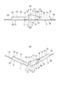
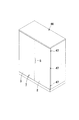
本発明係る引手付き折戸装置は、図1及び図2に示すように、二枚のパネル体2,3の連接縁6,7同士を近接配置するとともに、該連接縁6,7に沿った方向に1つの回動軸芯8を有するヒンジ4にて互に屈曲可能に連結して折戸1を形成し、該折戸1を開放する際に山折れする側であって、一方のパネル体2の連接縁6に沿って前記回動軸芯8を中心とする半円筒状の第一指掛部9を有する引手5を設けたものである。   As shown in FIGS. 1 and 2, the folding door device with a pulling handle according to the present invention places the connecting edges 6, 7 of the two panel bodies 2, 3 close to each other, and the direction along the connecting edges 6, 7. The folding door 1 is formed by being connected to each other by a hinge 4 having a single pivot axis 8, and the folding door 1 is folded when the folding door 1 is opened. A handle 5 having a semi-cylindrical first finger hook 9 centering on the rotation axis 8 is provided along the connecting edge 6.

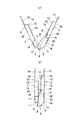
図1(a)は、二枚のパネル体2,3を直線状に開き、間仕切壁の出入口やキャビネット等の収納庫の開放部を閉鎖した状態に相当し、図1(b)は前記引手5を手前に引いて両パネル体2,3を前記ヒンジ4の回動軸芯8を中心として鈍角に屈曲させた状態を示し、図2(a)は更に両パネル体2,3を鋭角に屈曲させた状態を示し、図2(b)は両パネル体2,3を互いの裏面が重合するまで折畳んだ状態で、間仕切壁の出入口やキャビネット等の収納庫の開放部を開放した状態に相当している。この図1(a)から図2(b)までの一連の動作が折戸1の屈曲動作であり、その逆の動作が折戸1の伸展動作である。   FIG. 1A corresponds to a state in which the two panel bodies 2 and 3 are opened in a straight line, and the entrance / exit of the partition wall and the open part of the storage such as a cabinet are closed. FIG. 5 shows the state in which both panel bodies 2, 3 are bent at an obtuse angle about the pivot axis 8 of the hinge 4, and FIG. FIG. 2 (b) shows a state in which both panel bodies 2 and 3 are folded until their back surfaces are overlapped, and an opening of an entrance of a partition wall or a storage such as a cabinet is opened. It corresponds to. The series of operations from FIG. 1A to FIG. 2B is the bending operation of the folding door 1, and the reverse operation is the extending operation of the folding door 1.

ここで、前記折戸1は、前記第一指掛部9の外面と他方のパネル体3の連接縁7の端縁との間の隙間を、当該折戸1の屈曲伸展動作の全軌跡において、指が入らない略一定の間隔を維持するように設定している。   Here, the folding door 1 has a gap between the outer surface of the first finger hook 9 and the edge of the connecting edge 7 of the other panel body 3 in the entire locus of the bending extension operation of the folding door 1. It is set to maintain a substantially constant interval that does not enter.

更に詳しくは、前記パネル体2は、スチース製のものであり、表面板10の連接縁6側を裏面側へ略直角に折曲して端縁板11を形成し、前記表面板10の裏面で前記端縁板11に沿って補強部材12を固着している。この補強部材12は、中央部に裏面側へ突出した断面略コ字形の突台13を有し、その両側に外側へ開くように屈曲形成した固定板14,14を前記表面板10の裏面に溶接して取付けている。尚、外側の前記固定板14は、前記端縁板11の内面に当接するように位置決めされ、前記突台13の高さより前記端縁板11の高さを若干低く設定している。また、前記パネル体3は、前記パネル体2と同様の構造であるので、同一構造には同一符号を付して、その説明は省略する。   More specifically, the panel body 2 is made of steel, and the edge plate 11 is formed by bending the connecting edge 6 side of the surface plate 10 to the back surface side at a substantially right angle. The reinforcing member 12 is fixed along the end plate 11. The reinforcing member 12 has a protruding base 13 having a substantially U-shaped cross section that protrudes toward the back side at the center, and fixing plates 14 and 14 that are bent to open outward on both sides thereof are provided on the back side of the surface plate 10. It is welded and installed. The outer fixing plate 14 is positioned so as to contact the inner surface of the end plate 11, and the height of the end plate 11 is set slightly lower than the height of the protrusion 13. Further, since the panel body 3 has the same structure as the panel body 2, the same structure is denoted by the same reference numeral, and the description thereof is omitted.

前記ヒンジ4は、本実施形態では1つの回動軸芯8を有する通常の蝶番を採用し、前記回動軸芯8を、各パネル体2,3の裏面、即ち補強部材12の突台13の面より後方位置に設定し、両ウイング15,15を前記引手5を設けない上下適所の前記突台13にネジ止め若しくは溶接などの適宜な固定手段で取付けている。   In the present embodiment, the hinge 4 employs a normal hinge having a single pivot axis 8, and the pivot axis 8 is connected to the back surfaces of the panel bodies 2, 3, that is, the protrusion 13 of the reinforcing member 12. The wings 15 and 15 are attached to the upper and lower protrusions 13 where the handle 5 is not provided by appropriate fixing means such as screwing or welding.

そして、一方の前記パネル体2の連接縁6の一部、本実施形態では前記表面板10及び補強部材12の外側固定板14の一部とそれに連続する端縁板11を切欠して指を差し入れる開口部16を形成するとともに、該開口部16の内奥部に前記第一指掛部9を有する引手5を取付けている。ここで、本第1実施形態における引手5は、一端部に前記第一指掛部9となる半円筒状部分とそれに連続して前記開口部16の裏面側を覆い隠す傾斜板とを有するカバー部17を形成し、他端部に前記突台13の裏面に接合する取付板18を形成し、該取付板18を前記突台13の裏面にネジ19で取付けている。   Then, a part of the connecting edge 6 of the one panel body 2, in this embodiment, a part of the outer plate 14 and the outer fixing plate 14 of the reinforcing member 12 and the end edge plate 11 continuous therewith are cut out and fingers are placed. While forming the opening part 16 to insert, the handle 5 which has the said 1st finger hook part 9 in the inner back part of this opening part 16 is attached. Here, the handle 5 in the first embodiment is a cover having a semi-cylindrical portion serving as the first finger hook 9 at one end and an inclined plate covering the back side of the opening 16 continuously. A portion 17 is formed, and an attachment plate 18 to be joined to the back surface of the protrusion 13 is formed at the other end, and the attachment plate 18 is attached to the back surface of the protrusion 13 with screws 19.

更に、本実施形態では、前記開口部16より内方の表面板10の裏側に、前記補強部材12の固定板14の残余部分が存在し、前記突台13の側面及び前記引手5のカバー部17とで指を差し入れる空間部20を形成し、もって前記第一指掛部9と対向する前記パネル体2の縁部で、前記開口部16の内部に第二指掛部21を凹設しているのである。   Furthermore, in the present embodiment, the remaining portion of the fixing plate 14 of the reinforcing member 12 exists on the back side of the surface plate 10 inward from the opening 16, and the side surface of the projecting base 13 and the cover portion of the handle 5 17 to form a space 20 into which a finger is inserted, and a second finger hook 21 is recessed in the opening 16 at the edge of the panel body 2 facing the first finger hook 9. It is doing.

本実施形態のように、前記引手5を右側のパネル体2の左側連接縁6に設けた場合には、右手の指を第一指掛部9に掛け、左手の指を第二指掛部21に掛けることができるので、左右どちらの手でも折戸を開閉操作することができる。また、前記第一指掛部9となる引手5のカバー部17の外面と右側の前記パネル体3の連接縁7の端縁板11との隙間は、指が入らない略一定の間隔、実用的には数mm以内に設定している。前記折戸1の屈曲伸展動作時に、両パネル体2,3の相対的角度が前記ヒンジ4の回動軸芯8を中心として変化するが、両パネル体2,3はヒンジ4の両ウイング15,15に固定され、また前記カバー部17の外面は回動軸芯8を中心とする半円筒状であるので、図1(a)〜図2(b)に示すどのような屈曲状態においても前記カバー部17の外面と前記連接縁7の端縁板11との隙間は略一定になるのである。尚、前記引手5を左側のパネル体3の連接縁7に設けても同様である。   When the handle 5 is provided on the left connecting edge 6 of the right panel body 2 as in the present embodiment, the finger of the right hand is hung on the first finger hook 9 and the finger of the left hand is hooked on the second finger hook 21, the folding door can be opened and closed with either the left or right hand. Further, the gap between the outer surface of the cover portion 17 of the handle 5 serving as the first finger hooking portion 9 and the end edge plate 11 of the connecting edge 7 of the right panel body 3 is a substantially constant interval that does not allow a finger to enter. Specifically, it is set within several mm. When the folding door 1 is bent and extended, the relative angles of the panel bodies 2 and 3 change around the pivot axis 8 of the hinge 4. 15 and the outer surface of the cover portion 17 has a semi-cylindrical shape centering on the rotation axis 8. Therefore, the cover portion 17 is in any bent state as shown in FIGS. The gap between the outer surface of the cover portion 17 and the end edge plate 11 of the connecting edge 7 is substantially constant. The same applies when the handle 5 is provided on the connecting edge 7 of the left panel body 3.

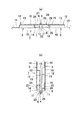
前記両パネル体2,3の連接縁6,7の間は目地部22となり、その中間部後方に前記ヒンジ4の回動軸芯8が平行に位置している。この目地部22は、前記引手5を設けた部分ではカバー部17が存在するので常に目隠し状態となっているが、その他の部分は何も設けなければ隙間が生じ、該目地部22を通して内外透視されたり、音が漏れたりするので、図3に示すように、本実施形態では可撓性のある素材で形成した閉塞部材23を目地部22に設けている。   Between the connecting edges 6 and 7 of both the panel bodies 2 and 3, it becomes the joint part 22, and the rotational axis 8 of the hinge 4 is located in parallel behind the intermediate part. The joint portion 22 is always in a blinded state in the portion where the handle 5 is provided because the cover portion 17 is present, but if no other portion is provided, a gap is formed, and the inside and outside perspective is seen through the joint portion 22. In this embodiment, a closing member 23 formed of a flexible material is provided on the joint portion 22 as shown in FIG.

前記閉塞部材23は、両端部の保持部24,25を硬質合成樹脂、中間部の遮蔽板26を可撓性のある軟質合成樹脂で二色成形して作成している。一方の前記保持部24は、断面略コ字形に成形し、前記パネル体3の連接縁7の裏側で、前記端縁板11と前記補強部材12の突台13の側面と外側固定板14とで形成された後方開放の凹溝27に移動不能に嵌合するとともに、前記ヒンジ4のウイング15で押えて保持している。他方の前記保持部25は、断面略L字形に成形し、前記パネル体2の連接縁6の裏側で、前記端縁板11と前記補強部材12の突台13の側面と外側固定板14とで形成された後方開放の凹溝28に横方向移動可能に嵌合するとともに、前記ヒンジ4のウイング15で押えて保持している。前記遮蔽板26は両保持部24,25にわたって成形され、前記ヒンジ4の前面側に位置し、前記目地部22を閉鎖している。   The closing member 23 is formed by two-color molding of the holding portions 24 and 25 at both ends with a hard synthetic resin and the intermediate shielding plate 26 with a flexible soft synthetic resin. One of the holding portions 24 is formed in a substantially U-shaped cross section, and on the back side of the connecting edge 7 of the panel body 3, the end plate 11, the side surface of the protrusion 13 of the reinforcing member 12, the outer fixing plate 14, Is fitted to the recessed groove 27 opened rearward so as to be immovable, and is held by being pressed by the wing 15 of the hinge 4. The other holding portion 25 is formed to have a substantially L-shaped cross section, and on the back side of the connecting edge 6 of the panel body 2, the end plate 11, the side surface of the protrusion 13 of the reinforcing member 12, the outer fixing plate 14, Is fitted to the recessed groove 28 opened rearward so as to be laterally movable, and is held by being pressed by the wing 15 of the hinge 4. The shielding plate 26 is formed over both the holding portions 24 and 25, is located on the front side of the hinge 4, and closes the joint portion 22.

図3(a)の状態から(b)の状態まで、両パネル板2,3を屈曲させると、前記閉塞部材23の遮蔽板26は前記ヒンジ4の回動軸芯8の外周を覆いながら断面U字状に屈曲するとともに、保持部25は引っ張られて前記凹溝28内を端縁板11側へ移動するが、どのような屈曲角度でも目地部22は遮蔽板26で閉鎖されている。   When the panel plates 2 and 3 are bent from the state shown in FIG. 3A to the state shown in FIG. 3B, the shielding plate 26 of the closing member 23 covers the outer periphery of the pivot shaft 8 of the hinge 4. While being bent in a U shape, the holding portion 25 is pulled and moves in the concave groove 28 toward the end plate 11, but the joint portion 22 is closed by the shielding plate 26 at any bending angle.

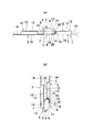
次に、図4に基づいて、本発明の引手付き折戸装置の第2実施形態を簡単に説明する。本実施形態は、引手5の取付構造が異なるのみで、その他の構成は前述の実施形態と同様である。本実施形態の引手5は、前記取付板18は存在せず、前記カバー部17の端部に、前記パネル体2の補強部材12の突台13の側面と外側固定板14とに接合する断面略L字形の取付部29を形成するとともに、該取付部29の端縁に前記開口部16の開口縁を覆う突縁30を形成したものである。そして、前記引手5の取付部29を前記補強部材12の突台13の側面と外側固定板14とに接合した状態で、ネジ31にて突台13の側面に取付けている。この場合、前記取付部29が前記第二指掛部21を兼ねることになる。その他の構成は、前記同様であるので、同一構造には同一符号を付して、その説明は省略する。   Next, based on FIG. 4, 2nd Embodiment of the folding door apparatus with a handle of this invention is described easily. This embodiment differs only in the attachment structure of the handle 5, and the other structure is the same as that of the above-mentioned embodiment. The handle 5 of the present embodiment has a cross section where the mounting plate 18 does not exist, and the side surface of the protruding base 13 of the reinforcing member 12 of the panel body 2 and the outer fixing plate 14 are joined to the end of the cover portion 17. A substantially L-shaped attachment portion 29 is formed, and a protruding edge 30 that covers the opening edge of the opening portion 16 is formed at the end edge of the attachment portion 29. And the attachment part 29 of the said handle 5 is attached to the side surface of the base 13 with the screw 31 in the state joined to the side surface of the base 13 of the said reinforcement member 12, and the outer side fixing plate 14. FIG. In this case, the attachment portion 29 also serves as the second finger hook portion 21. Since other configurations are the same as those described above, the same reference numerals are given to the same structures, and descriptions thereof are omitted.

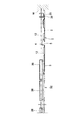
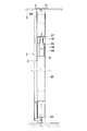
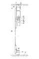
次に本発明の引手付き折戸装置の間仕切壁に適用した実施例を図5〜図9に基づき簡単に説明する。図5は間仕切壁を示す正面図であり、図6はその要部の横断平面図であり、図中符号1は折戸、32はスライドパネル、33は固定パネルをそれぞれ示している。また、図7及び図8はそれぞれ折戸1及びスライドパネル32の縦断側面図である。前記折戸1のパネル体2,3、スライドパネル32及び固定パネル33は、天井S近傍から床面F近傍にわたる、例えばスチール製等のパネル体であり、折戸1、スライドパネル32及び固定パネル33の上部が天レール34の前面を部分的に覆うように配置されている。本実施例では、壁面Wと固定パネル33の間の空間を、二対の折戸1,1とその中間に配置した二枚のスライドパネル32,32で開閉可能となした間仕切壁を構成している。   Next, the Example applied to the partition wall of the folding door apparatus with a handle of this invention is demonstrated easily based on FIGS. FIG. 5 is a front view showing the partition wall, FIG. 6 is a cross-sectional plan view of the main part, in which 1 is a folding door, 32 is a slide panel, and 33 is a fixed panel. 7 and 8 are longitudinal side views of the folding door 1 and the slide panel 32, respectively. The panel bodies 2 and 3, the slide panel 32, and the fixed panel 33 of the folding door 1 are panel bodies made of, for example, steel that extend from the vicinity of the ceiling S to the vicinity of the floor surface F. The folding door 1, the slide panel 32, and the fixed panel 33 The upper part is arranged so as to partially cover the front surface of the top rail 34. In the present embodiment, the partition wall is configured such that the space between the wall surface W and the fixed panel 33 can be opened and closed by two pairs of folding doors 1, 1 and two slide panels 32, 32 arranged in the middle. Yes.

ここで、前記折戸1は、一方のパネル体2の端部を、壁面W又は固定パネル33に沿って立設された支柱35にヒンジ36,…によって回動可能に取付けられ、他方のパネル体3の遊端上端を前記天レール34に沿って横設した吊下用ガイドレール37にランナー38によって移動可能に吊下げている。また、スライドパネル32,32も上部両側に取付けたランナー38,38で前記吊下用ガイドレール37の前面を覆うように、吊下用ガイドレール37より支持される前吊り構造となっている。   Here, the folding door 1 is rotatably attached at one end of one panel body 2 to a column 35 erected along the wall surface W or the fixed panel 33 by hinges 36. The upper end of the free end 3 is suspended by a runner 38 on a suspension guide rail 37 horizontally provided along the top rail 34. The slide panels 32 and 32 also have a front suspension structure that is supported by the suspension guide rail 37 so as to cover the front surface of the suspension guide rail 37 with runners 38 and 38 attached to both upper sides.

左側の折戸1の左側には固定パネル33,…が配設されている。固定パネル33,…は、天井Sに固定され水平方向に延びる天レール34と床面F上に固定され水平方向に延びる地レール39との間に多数の支柱35,35を立設させ、これらに囲まれる矩形状の空間を塞ぐように装着されている。尚、前記折戸1,1及びスライドパネル32,32下の床面Fには、地レール39を無くしている。また、折戸1,1及びスライドパネル32,32が前記前吊り構造であり、それぞれのパネル間の目地部40,…と折戸1の目地部22を同じ間隔に設定しているので、図5のように、固定パネル33,…と折戸1,1及びスライドパネル32,32とにより構成される間仕切壁全体の外観の連続性及び統一性が保たれている。   A fixed panel 33 is disposed on the left side of the left folding door 1. The fixed panel 33,... Has a large number of columns 35, 35 standing between a ceiling rail 34 fixed to the ceiling S and extending horizontally and a ground rail 39 fixed on the floor F and extending horizontally. It is mounted so as to close a rectangular space surrounded by In addition, the ground rail 39 is eliminated from the floor surface F under the folding doors 1 and 1 and the slide panels 32 and 32. Further, since the folding doors 1 and 1 and the slide panels 32 and 32 have the above-described suspension structure, the joint portions 40 between the panels and the joint portion 22 of the folding door 1 are set at the same interval. As described above, the continuity and uniformity of the appearance of the entire partition wall constituted by the fixed panels 33, ..., the folding doors 1, 1 and the slide panels 32, 32 are maintained.

図5及び図6に示すように、右側の折戸1は、右側パネル体2の端部を壁面Wに沿って固定した支柱35にヒンジ36,…を介して鉛直回動軸まわりに回動可能に連結している。また、左側の折戸1の左側パネル体3の端部を、固定パネル33を支持する支柱35に、同様にヒンジ36,…を介して鉛直回動軸まわりに回動可能に連結している。そして、右側の折戸1の左側パネル体3の遊端側の上部後面にランナー38が取付けられており、該ランナー38が吊下用ガイドレール37に支持されて該吊下用ガイドレール37に沿って水平方向に移動可能に構成されているため、引手5を持って手前に引けば折戸1を開けることができる。また、同様に折戸1を閉じることも容易に行うことができる。   As shown in FIGS. 5 and 6, the right folding door 1 can be rotated around a vertical rotation axis via a hinge 36,... On a column 35 in which an end of the right panel body 2 is fixed along the wall surface W. It is linked to. Further, the end portion of the left panel body 3 of the left folding door 1 is connected to a support column 35 that supports the fixed panel 33 so as to be rotatable around a vertical rotation axis through hinges 36. A runner 38 is attached to the upper rear surface on the free end side of the left panel body 3 of the right folding door 1, and the runner 38 is supported by the suspension guide rail 37 along the suspension guide rail 37. Therefore, the folding door 1 can be opened by holding the handle 5 and pulling it forward. Similarly, the folding door 1 can be easily closed.

さらに、図8に示すように、スライドパネル32の後面下部に、下方開放した凹溝を形成すべく振れ止め用カバー41を取付け、床面Fに固定された振れ止め用ローラー42を前記カバー41で形成された凹溝内で案内することにより、前記スライドパネル32,32の吊下用ガイドレール37に沿う水平方向の移動の容易化及び安定化を図っている。   Further, as shown in FIG. 8, an anti-slip cover 41 is attached to the lower part of the rear surface of the slide panel 32 so as to form a recessed groove that opens downward, and an anti-slip roller 42 fixed to the floor surface F is attached to the cover 41 In this way, the horizontal movement of the slide panels 32, 32 along the suspension guide rail 37 is facilitated and stabilized.

図5及び図7に示すように、折戸1,1下部には、床面F上に地レール及びガイドレール等の支持部材がないため、折戸1,1を開けた開口下部の床面Fには台車及び人等の通行の邪魔になる障害物がない構成となっている。したがって、開閉可能な間仕切壁をオフィス等における設備の点検又は収納等を行うスペースの区画用として使用した場合に、該スペースへの台車等による機材の搬入及び搬出等の作業をよりスムーズにかつ安全に行うことができる。尚、必要に応じて、折戸1,1と床面Fとの間にはマグネットキャッチ等の支持手段を設けることもできる。   As shown in FIG.5 and FIG.7, since there are no supporting members, such as a ground rail and a guide rail, on the floor surface F in the folding doors 1 and 1 lower part, the floor surface F of the opening lower part which opened the folding doors 1 and 1 is used. The structure has no obstacles that obstruct the passage of trolleys and people. Therefore, when the partition wall that can be opened and closed is used for partitioning a space for inspecting or storing equipment in an office or the like, the work of carrying equipment into and out of the space by means of a carriage etc. is smoother and safer. Can be done. If necessary, support means such as a magnet catch may be provided between the folding doors 1 and 1 and the floor surface F.

前記折戸1の遊動側のパネル体3の後面へ取付けるランナー38は、吊下用ガイドレール37に係合し該吊下用ガイドレール37に沿って移動可能なローラーを備えたランナー本体43、折戸1のパネル体3の裏面に直接又は間接に取付けるランナーベース44、ランナー本体43とランナーベース44とを吊下用ガイドレール37下部で鉛直回動軸Aまわりに回動可能に連結する連結体45により構成されている。   A runner 38 attached to the rear surface of the floating panel body 3 of the folding door 1 includes a runner main body 43 including a roller that engages with the suspension guide rail 37 and is movable along the suspension guide rail 37, and the folding door. A runner base 44 that is directly or indirectly attached to the back surface of one panel body 3, and a connecting body 45 that connects the runner body 43 and the runner base 44 so as to be rotatable around the vertical rotation axis A at the lower part of the suspension guide rail 37. It is comprised by.

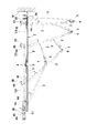
図9は、前記折戸1の動作説明用平面図である。ランナーベース44はパネル体3の遊端から延出させて該パネル体3の後面に取付けられ、ランナーベース44とランナー本体43との鉛直回動軸Aの位置は、ランナーベース44が取付けられたパネル体3の遊端からヒンジ4側と反対方向に所定距離だけ離れた位置となっている。従って、図9のように折戸1を折り畳む動作(矢印C1ないしC4参照。)によっても、ランナーベース44が取付けられたパネル体3の遊端と吊下用ガイドレール37の前面とが干渉しないように構成されている。   FIG. 9 is a plan view for explaining the operation of the folding door 1. The runner base 44 extends from the free end of the panel body 3 and is attached to the rear surface of the panel body 3. The runner base 44 is attached to the runner base 44 and the runner body 43 at the position of the vertical rotation axis A. The position is a predetermined distance away from the free end of the panel body 3 in the direction opposite to the hinge 4 side. Therefore, even when the folding door 1 is folded (see arrows C1 to C4) as shown in FIG. 9, the free end of the panel body 3 to which the runner base 44 is attached and the front surface of the suspension guide rail 37 do not interfere with each other. It is configured.

図5、図6及び図8に示すように、スライドパネル32は、後面上部にランナー38,38が取付けられており、該ランナー38が吊下用ガイドレール37に水平方向に移動可能となっているので、ガイドレール37に沿って水平方向に移動させることができる。また、床面Fには振れ止め用ローラー42が固定されるのみであり、このローラー42は振れ止め用カバー41により覆われて外部からは見えないため、安全上及び意匠上も好ましい構成であるといえる。更に、スライドパネル32を開けた状態において、その開口下部には振れ止め等の支持部材がないため、スライドパネル32,32を開けた開口下部の床面Fには台車及び人等の通行の邪魔になる障害物がない構成となっている。   As shown in FIGS. 5, 6, and 8, the slide panel 32 has runners 38 attached to the upper rear surface, and the runner 38 can move horizontally to the suspension guide rail 37. Therefore, it can be moved along the guide rail 37 in the horizontal direction. Further, only the steadying roller 42 is fixed to the floor surface F, and this roller 42 is covered with the steadying cover 41 and cannot be seen from the outside. Therefore, the configuration is also preferable in terms of safety and design. It can be said. Further, in the state where the slide panel 32 is opened, since there is no support member such as a steady rest at the lower part of the opening, the floor F at the lower part of the opening where the slide panels 32 and 32 are opened obstructs the passage of carts and people. There is no obstacle to become.

次に、図10に基づいて本発明の実施例2を説明する。前記折戸1をキャビネット本体46の前面開放部に設け、該折戸1によって前面開放部を開閉するものである。前記同様に、前記折戸1の一方のパネル体2の端部をヒンジ47,…によって回動可能に取付け、更に図示しないが他方のパネル体3の遊端上下部に鉛直回転軸を有するローラー又はスライダーを突設し、前面開放部の上下框部に設けた上下レールに横方向スライド可能に係合させて案内している。   Next, a second embodiment of the present invention will be described with reference to FIG. The folding door 1 is provided in the front opening portion of the cabinet body 46, and the front opening portion is opened and closed by the folding door 1. Similarly, the end of one panel body 2 of the folding door 1 is rotatably attached by hinges 47,..., And although not shown, a roller having a vertical rotation shaft at the upper and lower ends of the other panel body 3 A slider is provided so as to be guided by being slidably engaged with the upper and lower rails provided on the upper and lower flanges of the front opening.

本発明の第1実施形態に係る折戸装置の要部を示し、(a)は二枚のパネル体が直線状の閉じた状態を示す横断面図、(b)は二枚のパネル体を鈍角に屈曲した状態の横断面図である。The principal part of the folding door apparatus which concerns on 1st Embodiment of this invention is shown, (a) is a cross-sectional view which shows the state which two panel bodies closed linearly, (b) is an obtuse angle of two panel bodies. FIG. 同じく本発明に係る折戸装置の要部を示し、(a)は二枚のパネル体を鋭角に屈曲した状態の横断面図、(b)は二枚のパネル体を互いの裏面が重合するまで折畳んだ状態の横断面図である。The main part of the folding door apparatus which similarly concerns on this invention is shown, (a) is a cross-sectional view of the state which bent two panel bodies at an acute angle, (b) is until the back surface mutually superimposes two panel bodies. It is a cross-sectional view of the folded state. 二枚のパネル体の間の目地部の構造を示し、(a)は二枚のパネル体が直線状の閉じた状態を示す横断面図、(b)は二枚のパネル体を互いの裏面が重合するまで折畳んだ状態の横断面図である。The structure of the joint part between two panel bodies is shown, (a) is a cross-sectional view showing a state in which the two panel bodies are linearly closed, and (b) is the back side of the two panel bodies. It is a cross-sectional view of the state folded until superposition | polymerization. 本発明の第2実施形態に係る折戸装置の要部を示し、(a)は二枚のパネル体が直線状の閉じた状態を示す横断面図、(b)は二枚のパネル体を互いの裏面が重合するまで折畳んだ状態の横断面図である。The principal part of the folding door apparatus which concerns on 2nd Embodiment of this invention is shown, (a) is a cross-sectional view which shows the state which two panel bodies closed linearly, (b) is two panel bodies mutually. It is a cross-sectional view of the folded state until the back surface of the polymerized. 本発明に係る折戸装置を間仕切壁に適用した実施例1を示す簡略正面図である。It is a simplified front view which shows Example 1 which applied the folding door apparatus which concerns on this invention to the partition wall. 同じく要部の横断面図である。Similarly it is a cross-sectional view of the main part. 同じく間仕切壁の折戸を設けた部分の縦断面図である。It is the longitudinal cross-sectional view of the part which similarly provided the folding door of the partition wall. 同じく間仕切壁のスライドパネルを設けた部分の縦断面図である。It is the longitudinal cross-sectional view of the part which similarly provided the slide panel of the partition wall. 同じく間仕切壁における折戸の動作説明用平面図である。It is a top view for operation | movement explanation of the folding door in a partition wall similarly. 本発明に係る折戸装置をキャビネットに適用した実施例2を示す簡略斜視図である。It is a simplified perspective view which shows Example 2 which applied the folding door apparatus which concerns on this invention to the cabinet.

符号の説明Explanation of symbols

1 折戸 2 パネル体
3 パネル体 4 ヒンジ
5 引手 6 連接縁
7 連接縁 8 回動軸芯
9 第一指掛部 10 表面板
11 端縁板 12 補強部材
13 突台 14 固定板
15 ウイング 16 開口部
17 カバー部 18 取付板
19 ネジ 20 空間部
21 第二指掛部 22 目地部
23 閉塞部材 24 保持部
25 保持部 26 遮蔽板
27 凹溝 28 凹溝
29 取付部 30 突縁
31 ネジ 32 スライドパネル
33 固定パネル 34 天レール
36 ヒンジ 37 吊下用ガイドレール
38 ランナー 39 地レール
40 目地部 41 カバー
42 ローラー 43 ランナー本体
44 ランナーベース 45 連結体
46 キャビネット本体 47 ヒンジ
F 床面 S 天井
W 壁面
DESCRIPTION OF SYMBOLS 1 Folding door 2 Panel body 3 Panel body 4 Hinge 5 Pull 6 Connection edge 7 Connection edge 8 Rotating shaft core 9 First finger hook part 10 Surface board 11 End edge board 12 Reinforcement member 13 Projection base 14 Fixing board 15 Wing 16 Opening part 17 Cover part 18 Mounting plate 19 Screw 20 Space part 21 Second finger hook part 22 Joint part 23 Closure member 24 Holding part 25 Holding part 26 Shielding plate 27 Groove 28 Groove 29 Mounting part 30 Projection edge 31 Screw 32 Slide panel 33 Fixed panel 34 Top rail 36 Hinge 37 Suspension guide rail 38 Runner 39 Ground rail 40 Joint section 41 Cover 42 Roller 43 Runner main body 44 Runner base 45 Connection body 46 Cabinet main body 47 Hinge F Floor surface S Ceiling W Wall surface

Claims (5)

二枚のパネル体の連接縁同士を近接配置するとともに、該連接縁に沿った方向に1つの回動軸芯を有するヒンジにて互に屈曲可能に連結して折戸を形成し、該折戸を開放する際に山折れする側であって、一方のパネル体の連接縁に沿って前記回動軸芯を中心とする半円筒状の第一指掛部を有する引手を設けたことを特徴とする引手付き折戸装置。   The connecting edges of the two panel bodies are arranged close to each other, and connected to each other by a hinge having one pivot axis in the direction along the connecting edges to form a folding door. A pulling handle having a semi-cylindrical first finger hook portion centering on the rotation axis is provided along a connecting edge of one panel body on a side that is bent when being opened. Folding door device with handle. 前記第一指掛部の外面と他方のパネル体の連接縁の端縁との間の隙間を、前記折戸の屈曲伸展動作の全軌跡において、指が入らない略一定の間隔に設定してなる請求項1記載の引手付き折戸装置。   The gap between the outer surface of the first finger hook portion and the edge of the connecting edge of the other panel body is set at a substantially constant interval where fingers do not enter in the entire trajectory of the folding and extending operation of the folding door. The folding door apparatus with a handle according to claim 1. 前記ヒンジの回動軸芯を、各パネル体の裏面より後方位置に設定してなる請求項1又は2記載の引手付き折戸装置。   The folding door apparatus with a handle according to claim 1 or 2, wherein the pivot axis of the hinge is set at a rear position from the back surface of each panel body. 一方の前記パネル体の連接縁の一部を切欠して指を差し入れる開口部を形成するとともに、該開口部の内奥部に前記第一指掛部を有する引手を取付けてなる請求項1〜3何れかに記載の引手付き折戸装置。   2. A part of the connecting edge of one of the panel bodies is cut out to form an opening for inserting a finger, and a handle having the first finger hooking part is attached to the inner back of the opening. The folding door device with a handle according to any one of? 3. 前記第一指掛部と対向する前記パネル体の縁部で、前記開口部の内部に第二指掛部を凹設してなる請求項4記載の引手付き折戸装置。   The folding door apparatus with a handle according to claim 4, wherein a second finger hooking portion is recessed in the opening at an edge of the panel body facing the first finger hooking portion.
JP2004104728A 2004-03-31 2004-03-31 Folding door device with handle Withdrawn JP2005290735A (en)

Priority Applications (1)

Application Number Priority Date Filing Date Title
JP2004104728A JP2005290735A (en) 2004-03-31 2004-03-31 Folding door device with handle

Applications Claiming Priority (1)

Application Number Priority Date Filing Date Title
JP2004104728A JP2005290735A (en) 2004-03-31 2004-03-31 Folding door device with handle

Publications (1)

Publication Number Publication Date
JP2005290735A true JP2005290735A (en) 2005-10-20

Family

ID=35323984

Family Applications (1)

Application Number Title Priority Date Filing Date
JP2004104728A Withdrawn JP2005290735A (en) 2004-03-31 2004-03-31 Folding door device with handle

Country Status (1)

Country Link
JP (1) JP2005290735A (en)

Cited By (1)

* Cited by examiner, † Cited by third party
Publication number Priority date Publication date Assignee Title
WO2021022595A1 (en) * 2019-08-08 2021-02-11 东莞市楷模家居用品制造有限公司 Connection mechanism for upturning and folding door, and furniture having same

Cited By (1)

* Cited by examiner, † Cited by third party
Publication number Priority date Publication date Assignee Title
WO2021022595A1 (en) * 2019-08-08 2021-02-11 东莞市楷模家居用品制造有限公司 Connection mechanism for upturning and folding door, and furniture having same

Similar Documents

Publication Publication Date Title
HU223211B1 (en) Garage door
JPH02183080A (en) Door
JP2005290735A (en) Folding door device with handle
GB2213185A (en) Door assembly, particularly for shower enclosures
JP4123202B2 (en) Folding door device
JP7359667B2 (en) opening/closing body
JP4634335B2 (en) Flat sliding door device
AU2002302076B2 (en) Concertina panel wall
JPH0637480U (en) Storage box
JP2697486B2 (en) Panel hinge mechanism
JP4002597B2 (en) sliding door
JP3331495B2 (en) Sliding door system
JP2589363Y2 (en) Hinge
JPH0113752Y2 (en)
JPH0328130Y2 (en)
JPH0420809B2 (en)
JP3691666B2 (en) Storage furniture
JPS588855Y2 (en) assembly storage
JP6961515B2 (en) Arc-shaped door device for booth
JP2010077797A (en) Gateway device
JP4192787B2 (en) Sliding door-to-door structure
JPH0717551Y2 (en) Van body back door fixing device
JPS6347259Y2 (en)
JPH0624187U (en) Lower rail groove closing device
JPH0565026A (en) Support structure for slide door

Legal Events

Date Code Title Description
A300 Withdrawal of application because of no request for examination

Free format text: JAPANESE INTERMEDIATE CODE: A300

Effective date: 20070605