JP2005290727A - Construction equipment - Google Patents
Construction equipment Download PDFInfo
- Publication number
- JP2005290727A JP2005290727A JP2004104547A JP2004104547A JP2005290727A JP 2005290727 A JP2005290727 A JP 2005290727A JP 2004104547 A JP2004104547 A JP 2004104547A JP 2004104547 A JP2004104547 A JP 2004104547A JP 2005290727 A JP2005290727 A JP 2005290727A
- Authority
- JP
- Japan
- Prior art keywords
- boom foot
- main rails
- pin
- building cover
- construction machine
- Prior art date
- Legal status (The legal status is an assumption and is not a legal conclusion. Google has not performed a legal analysis and makes no representation as to the accuracy of the status listed.)
- Granted
Links
- 238000010276 construction Methods 0.000 title claims abstract description 29
- 238000012423 maintenance Methods 0.000 claims description 11
- 239000002828 fuel tank Substances 0.000 abstract description 24
- 238000003780 insertion Methods 0.000 abstract description 6
- 230000037431 insertion Effects 0.000 abstract description 6
- 239000010720 hydraulic oil Substances 0.000 description 4
- 238000000034 method Methods 0.000 description 2
- 239000003921 oil Substances 0.000 description 2
- 108010066114 cabin-2 Proteins 0.000 description 1
- 238000007796 conventional method Methods 0.000 description 1
- 230000012447 hatching Effects 0.000 description 1
- 238000012986 modification Methods 0.000 description 1
- 230000004048 modification Effects 0.000 description 1
Images
Landscapes
- Component Parts Of Construction Machinery (AREA)
Abstract
Description
本発明は、左右一対のメインレールにブームフートピンが挿通され、上記の左右一対のメインレールの外側の一方に建屋カバーが配置されるとともに上記外側の他方に所定のコンポーネントが配置された、建設機械に関する。 The present invention is a construction in which a boom foot pin is inserted into a pair of left and right main rails, a building cover is disposed on one of the outer sides of the pair of left and right main rails, and a predetermined component is disposed on the other of the outer sides. Related to machinery.
図5は、走行式の建設機械である油圧ショベルの一般的な構成を示す模式的な側面図である。この油圧ショベルは、図示するように、下部走行体101と、キャビン102aを有し下部走行体101の上側に旋回可能に設置された上部旋回体102と、上部旋回体102に設けられ種々の作業を行なう作業装置103との3つの部分で構成されている。
作業装置103は、基端部(ブームフート)104aが上部旋回体2に上下揺動自在に連結されるブーム104と、このブーム104の先端部に前後揺動自在に連結されるアーム105と、アーム105の先端部に前後揺動自在に連結されるバケット106とをそなえて構成されている。
FIG. 5 is a schematic side view showing a general configuration of a hydraulic excavator that is a traveling construction machine. As shown in the figure, the hydraulic excavator includes a
The
そして、これは一般的なレイアウトであるが、図6に示すように、ブームフート104aの上部旋回体102への連結部C及びブームフートピンPの左右両側にそれぞれキャビン102a、所定のコンポーネント(一般的に作動油タンクや燃料タンクなど油タンクであり、ここでは燃料タンク)110が配置されている。換言すれば、キャビン102a,ブームフートピンP及び燃料タンク110が基体前後方向に対し略同位置とされている。
This is a general layout. As shown in FIG. 6, the
そして、このようにブームフートピンPの左右両側にはキャビン102a及び燃料タンク110が配置されているため、ブームフートピンPの脱着を容易に行なえるよう、ここでは、上記ブームフートピンPを脱着するためのスペースを確保すべく、燃料タンク110に、上記ブームフートピンPの軸心の延長線上に位置する切欠110aが設けられている(例えば特許文献1参照)。
Since the
また、このような切欠(空間部)にピン着脱時に取り外し可能な燃料タンク増量部を設置した技術も提案されている(特許文献2参照)。
しかしながら、上記の特許文献1に示す従来技術では、燃料タンクに切欠を設けることから燃料タンクの形状が複雑となるとともに、この切欠分だけ燃料タンクの容量が減少する。また、上記の特許文献2に示す従来技術では、特許文献1に較べ、燃料タンク増量部を設ける分、油貯蔵量を増加できるが、上記燃料タンク増量部を燃料タンクに取り外し可能に構成するため、構造が複雑となる。
However, in the prior art disclosed in Patent Document 1, since the fuel tank is provided with a notch, the shape of the fuel tank is complicated, and the capacity of the fuel tank is reduced by this notch. Further, in the conventional technique shown in
本発明はこのような課題に鑑み創案されたもので、ブームフートピンの挿脱を容易に行なえ、且つ、燃料タンクや作動油タンクなどの所定のコンポーネントにおけるレイアウト上の制約の軽減及び構成の簡素化を実現できるようにした、建設機械を提供することを目的とする。 The present invention has been devised in view of such a problem, and allows the boom foot pin to be easily inserted and removed, and reduces the restrictions on the layout of a predetermined component such as a fuel tank or a hydraulic oil tank, and simplifies the configuration. The purpose is to provide a construction machine that can be realized.
上記目的を達成するために、請求項1記載の本発明の建設機械は、上部旋回体の底部をなすスイングフレームに対し立設された左右一対のメインレールにブームフートピンが挿通され、上記の左右一対のメインレールの外側一方に建屋カバーが配置されるとともに外側他方に所定のコンポーネントが配置された、建設機械において、該ピンが、上記の左右一対のメインレールに対し、上記の建屋カバーのある外側一方へ引き抜き可能に取り付けられるとともに、該建屋カバーの一部であって取り外し可能な取り外し部が、該メインレールに対し該ピンを脱着する際の該ピンの移動経路上配置されたことを特徴としている。 In order to achieve the above object, the construction machine according to the first aspect of the present invention includes a boom foot pin inserted through a pair of left and right main rails erected with respect to a swing frame that forms the bottom of the upper swing body. In a construction machine in which a building cover is disposed on one outer side of the pair of left and right main rails and a predetermined component is disposed on the other outer side, the pin is connected to the pair of left and right main rails with respect to the pair of left and right main rails. It is removably attached to one outer side, and a removable part that is a part of the building cover and that is removable is disposed on the movement path of the pin when the pin is attached to and detached from the main rail. It is a feature.
請求項2記載の本発明の建設機械は、請求項1記載の建設機械において、該取り外し部が、該建屋カバー内の所定機器用のメンテナンス空間に面して配置されたことを特徴としている。 A construction machine according to a second aspect of the present invention is characterized in that, in the construction machine according to the first aspect, the removing portion is disposed facing a maintenance space for a predetermined device in the building cover.
本発明の建設機械によれば、ブームフートピンが、左右一対のメインレールに対し、建屋カバーのある一方の側へ引き抜き可能に取り付けられるとともに、建屋カバーの取り外し部を、メインレールに対しブームフートピンを脱着する際のブームフートピンの移動経路上配置しているので、上記取り外し部を外すことにより、上記一方の側からブームフートピンの挿脱を行なえ、したがって、ブームフートピンの挿脱を容易に行なえ、且つ、上記の左右一対のメインレールに対し他方の側にある燃料タンクや作動油タンクなどの所定のコンポーネントにおけるレイアウト上の制約の軽減及び構成の簡素化を実現できる利点がある。 According to the construction machine of the present invention, the boom foot pin is attached to the pair of left and right main rails so that the boom foot pin can be pulled out to one side of the building cover, and the removal portion of the building cover is attached to the boom rail. Since it is arranged on the movement path of the boom foot pin when the pin is attached / detached, the boom foot pin can be inserted / removed from the one side by removing the removing portion. There is an advantage that it can be easily performed, and the restriction on the layout and the configuration can be reduced in a predetermined component such as a fuel tank or a hydraulic oil tank on the other side of the pair of left and right main rails.
また、取り外し部を、建屋カバー内の所定機器用のメンテナンス空間に面して配置すれば、上記メンテナンス空間を移動経路として利用することができる。 Further, if the detaching portion is arranged facing the maintenance space for the predetermined device in the building cover, the maintenance space can be used as a movement path.
以下、図面を参照しながら本発明の実施の形態について説明する。
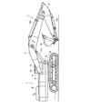
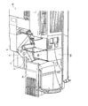
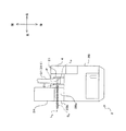
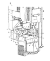
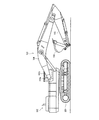
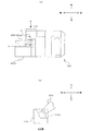
図1〜図4は本発明の一実施形態の建設機械を説明するための図であって、図1はその全体構成を示す模式的な側面図、図2はその要部構成を示す模式的な斜視図(建屋カバーのトップカバー及びサイドカバーを取り付けた状態で示す図)、図3はその要部構成を示す模式的な平面図、図4はそのブームフートピンの挿脱を説明するための図であって、その要部構成を示す模式的な斜視図(建屋カバーのトップカバー及びサイドカバーを取り外した状態で示す図)である。なお、図2ではブームフート及びブームフートピンを省略し、図4ではブームフートを省略している。
Hereinafter, embodiments of the present invention will be described with reference to the drawings.
1-4 is a figure for demonstrating the construction machine of one Embodiment of this invention, FIG. 1 is typical side view which shows the whole structure, FIG. 2 is typical which shows the principal part structure. FIG. 3 is a schematic plan view showing the configuration of the main part, and FIG. 4 is for explaining the insertion and removal of the boom foot pin. FIG. 3 is a schematic perspective view showing the configuration of the main part (a view showing a state in which a top cover and a side cover of the building cover are removed). In FIG. 2, the boom foot and the boom foot pin are omitted, and the boom foot is omitted in FIG.
先ず、建設機械(ここでは油圧ショベル)の全体構成について説明すると、図1に示すように、建設機械は、下部走行体1と、下部走行体1の上側に旋回可能に配設された上部旋回体2と、上部旋回体2に設けられ種々の作業を行なう作業装置3の3つの部分で構成されている。
作業装置3は、基端部(ブームフート)311が上部旋回体2に上下揺動自在に軸支されるブーム31と、このブーム31の先端部に前後揺動自在に連結されるアーム32と、アーム32の先端部に前後揺動自在に連結されるバケット33と、上記ブーム31,アーム32及びバケット33を作動させるためのブームシリンダ31a,アームシリンダ32a及びバケットシリンダ33aとをそなえて構成されている。
First, the overall configuration of a construction machine (here, a hydraulic excavator) will be described. As shown in FIG. 1, the construction machine includes a lower traveling body 1 and an upper swing that is disposed on the upper side of the lower traveling body 1 so as to be pivotable. The
The work device 3 includes a
図2〜図4に示すように、上部旋回体2には、その機体前側において、後述するメインレール21,21を挟むようにして、左側にキャビン2Aが配置されるとともに右側に燃料タンク(所定のコンポーネント)4が配置され、これらのキャビン2A,燃料タンク4の後方に、内部にエンジンルームなどが配置された建屋カバー2Bが配置されている。
また、ブームフート311は、上部旋回体2の台枠をなすスゥイングフレームSFに立設された左右一対のメインレール21,21と共にブームフートピンPにより水平方向に挿通されており、上記メインレール21,21の相互間において上下に揺動自在に支持されている。
As shown in FIGS. 2 to 4, the
The
そして、メインレール21,21のブームフートピンPの取付部の外側一方(一方のメインレール21の他方のメインレール21に向き合わない側、ここでは機体左側のメインレール21の左側)には、建屋カバー2Bの左前端が位置し、上記取付部の外側他方(他方のメインレール21の一方のメインレール21に向き合わない側、ここでは機体右側のメインレール21の右側)には、燃料タンク(所定のコンポーネント)4が位置している。
On the outer side of the mounting portion of the boom foot pin P of the
上記建屋カバー2Bの左前端(キャビン2Aの後方)には、各種コントローラ51やリレーボックス52などの所定機器が収容されている。通常は、これらのコントローラ51やリレーボックス52などは建屋カバー2Bにより保護されているが、建屋カバー2Bにおける左前端をなすトップカバー2Ba及びサイドカバー2Bbは従来より取り外し可能になっており、メンテナンスを行なう際には、これらのカバー(取り外し部)2Ba,2Bbが外されるようになっている。つまり、上記所定機器のメンテナンスを行なうためのメンテナンス空間に面して、上記の取り外し可能なカバー2Ba,2Bbが配置されているのである。
Predetermined devices such as
なお、上記のコントローラ51やリレーボックス52は、キャビン2Aの後方のバックプレート50にボルト止めされている。
図3に示すように、建設機械の組み立て時やメンテナンス時のブームフートピンPの挿脱は、メインレール21,21及びブームフート311に装着状態におけるブームフートピンPの軸心線LPの延長線LE上を移動させることにより行なわれ、さらに、ブームフートピンPの挿脱は、従来では燃料タンク側で行なわれていたのに対し、ブームフートピンPを、メインレール21やブームフート311からキャビン2A側へと引き抜けるようになっていおり、ブームフートピンPの挿脱時の移動経路SPは図3中に斜線で示すように上記延長線LE上に形成される。
The
As shown in FIG. 3, the boom foot pin P is inserted / removed when the construction machine is assembled or maintenance is performed by extending the shaft center line L P of the boom foot pin P in the state of being attached to the
そして、ここでは、この移動経路SP上に、上記のトップカバー2Ba及びサイドカバー2Bbが配置されている(逆の見方をすれば、トップカバー2Ba及びサイドカバー2Bbを貫通するように移動経路SPが設定されている)。 And here, on the movement path S P, if the view of the (reverse above top cover 2Ba and the side cover 2Bb is located, the moving path S so as to penetrate the top cover 2Ba and the side cover 2Bb P is set).
本発明の一実施形態としての建設機械はこのように構成されており、図4に示すようにしてブームフートピンPの挿脱が行なわれる。
つまり、先ず、メインレール21,21のブームフートピン挿入部の横に位置する、建屋カバー2Bのトップカバー2Ba及びサイドカバー2Bbが外される。これにより、従来よりコントローラやリレーボックスなどのメンテナンスを行なうために利用していた空間(メンテナンス空間)Vを、そのまま、ブームフートピンPを挿脱するための移動経路として使用できる状態となる。
The construction machine as one embodiment of the present invention is configured as described above, and the boom foot pin P is inserted and removed as shown in FIG.
That is, first, the top cover 2Ba and the side cover 2Bb of the
そして、作業者がブームフートピンPを、メインレール21,21及びブームフートからキャビン2A側に引き抜き、或いは、キャビン2A側からメインレール21,21及びブームフートに挿入する。例えば、ブームフートピンPを挿入し取り付けるときは、ブームフートピンPを、その一端に固定された取付用プレートP1を図示するように上方に向けた水平姿勢でメインレール21,21に取付位置まで挿入する。そして、矢印Fで示すように所定量回転させて、上記取付用プレートP1に設けられた挿通穴P2と、メインレール21に設けられたボルト穴21aとを一致させ、これらの挿通穴P2とボルト穴21aとにワッシャWを通してボルトBを取り付け、ブームフートピンPの取り付けが完了する。
Then, the operator pulls out the boom foot pin P from the
このように、本建設機械によれば、ブームフートピンPの挿脱をキャビン2A側で行なえるので、その反対側においてブームフートピンPの通る空間(移動経路)が不要となる分、上記特許文献1のように切欠の設けられた燃料タンクに比べ、燃料タンク4の容量を増大することができる。
そして、上記特許文献2の技術は、燃料タンク増量部を取り外し可能に設けており燃料タンク廻りの構成が複雑であったが、本建設機械によれば、このようなタンク増量部を設けることなく、燃料タンクや作動油タンクの容量を十分なものにできる利点がある。
Thus, according to this construction machine, since the boom foot pin P can be inserted and removed on the
In the technique disclosed in
本発明の建設機械は、上記実施形態に限定されず、本発明の趣旨を逸脱しない範囲で種々変形することが可能である。
例えば、上記実施形態では、トップカバー2Ba及びサイドカバー2Bbを取り外し可能な構成としたが、少なくとも、ブームフートピンPの移動経路SP上に位置するサイドカバー2Bbに相当する部位を取り外し可能とすれば良い。
The construction machine of the present invention is not limited to the above embodiment, and various modifications can be made without departing from the spirit of the present invention.
By example, in the above embodiment, a removable constituting the top cover 2Ba and the side cover 2Bb, at least, a removable portion corresponding to the side cover 2Bb located on the movement path S P output boom foot pin P It ’s fine.
2 上部旋回体
21 メインレール
2B 建屋カバー
2Ba トップカバー(建屋カバーの取り外し部)
2Bb サイドカバー(建屋カバーの取り外し部)
P ブームフートピン
SP ブームフートピンの移動経路
SF スイングフレーム
V メンテナンス空間
2
2Bb Side cover (removal part of building cover)
P Boom foot pin S P Boom foot pin travel path SF Swing frame V Maintenance space
Claims (2)
該ピンが、上記の左右一対のメインレールに対し、上記の建屋カバーのある外側一方へ引き抜き可能に取り付けられるとともに、
該建屋カバーの一部であって取り外し可能な取り外し部が、該メインレールに対し該ピンを脱着する際の該ピンの移動経路上配置された
ことを特徴とする、建設機械。 Boom foot pins are inserted into a pair of left and right main rails erected with respect to the swing frame that forms the bottom of the upper swing body, and a building cover is disposed on one outer side of the pair of left and right main rails, and a predetermined value is set on the other outer side. In the construction machine where the components of
The pins are attached to the pair of left and right main rails so that they can be pulled out to the outer side with the building cover,
A construction machine, wherein a removable part that is a part of the building cover and is removable is arranged on a movement path of the pin when the pin is attached to and detached from the main rail.
ことを特徴とする、請求項1記載の建設機械。 2. The construction machine according to claim 1, wherein the detaching portion is disposed facing a maintenance space for a predetermined device in the building cover.
Priority Applications (1)
| Application Number | Priority Date | Filing Date | Title |
|---|---|---|---|
| JP2004104547A JP4448725B2 (en) | 2004-03-31 | 2004-03-31 | Construction machinery |
Applications Claiming Priority (1)
| Application Number | Priority Date | Filing Date | Title |
|---|---|---|---|
| JP2004104547A JP4448725B2 (en) | 2004-03-31 | 2004-03-31 | Construction machinery |
Publications (2)
| Publication Number | Publication Date |
|---|---|
| JP2005290727A true JP2005290727A (en) | 2005-10-20 |
| JP4448725B2 JP4448725B2 (en) | 2010-04-14 |
Family
ID=35323976
Family Applications (1)
| Application Number | Title | Priority Date | Filing Date |
|---|---|---|---|
| JP2004104547A Expired - Fee Related JP4448725B2 (en) | 2004-03-31 | 2004-03-31 | Construction machinery |
Country Status (1)
| Country | Link |
|---|---|
| JP (1) | JP4448725B2 (en) |
Cited By (8)
| Publication number | Priority date | Publication date | Assignee | Title |
|---|---|---|---|---|
| JP2010106522A (en) * | 2008-10-30 | 2010-05-13 | Hitachi Constr Mach Co Ltd | Swivel-type construction machine |
| JP2014141837A (en) * | 2013-01-24 | 2014-08-07 | Kobelco Contstruction Machinery Ltd | Work machine |
| JP2014224365A (en) * | 2013-05-15 | 2014-12-04 | 住友建機株式会社 | Construction machine |
| US9103092B2 (en) | 2011-02-18 | 2015-08-11 | Kobelco Construction Machinery Co., Ltd. | Hybrid construction machine |
| JP2016069864A (en) * | 2014-09-29 | 2016-05-09 | コベルコ建機株式会社 | Interior arrangement structure of construction machinery |
| WO2016147920A1 (en) * | 2015-03-17 | 2016-09-22 | ヤンマー株式会社 | Support shaft member mounting/dismounting structure for working machine |
| WO2016147921A1 (en) * | 2015-03-17 | 2016-09-22 | ヤンマー株式会社 | Support shaft member mounting/dismounting structure for working machine |
| JP2017180013A (en) * | 2016-03-31 | 2017-10-05 | コベルコ建機株式会社 | Work machine |
-
2004
- 2004-03-31 JP JP2004104547A patent/JP4448725B2/en not_active Expired - Fee Related
Cited By (11)
| Publication number | Priority date | Publication date | Assignee | Title |
|---|---|---|---|---|
| JP2010106522A (en) * | 2008-10-30 | 2010-05-13 | Hitachi Constr Mach Co Ltd | Swivel-type construction machine |
| US9103092B2 (en) | 2011-02-18 | 2015-08-11 | Kobelco Construction Machinery Co., Ltd. | Hybrid construction machine |
| CN103547740B (en) * | 2011-02-18 | 2016-03-02 | 神钢建设机械株式会社 | Hybrid power engineering machinery |
| JP2014141837A (en) * | 2013-01-24 | 2014-08-07 | Kobelco Contstruction Machinery Ltd | Work machine |
| JP2014224365A (en) * | 2013-05-15 | 2014-12-04 | 住友建機株式会社 | Construction machine |
| JP2016069864A (en) * | 2014-09-29 | 2016-05-09 | コベルコ建機株式会社 | Interior arrangement structure of construction machinery |
| WO2016147920A1 (en) * | 2015-03-17 | 2016-09-22 | ヤンマー株式会社 | Support shaft member mounting/dismounting structure for working machine |
| WO2016147921A1 (en) * | 2015-03-17 | 2016-09-22 | ヤンマー株式会社 | Support shaft member mounting/dismounting structure for working machine |
| JP2016172977A (en) * | 2015-03-17 | 2016-09-29 | ヤンマー株式会社 | Attachment/detachment structure for support shaft member of work machine |
| JP2016172978A (en) * | 2015-03-17 | 2016-09-29 | ヤンマー株式会社 | Attachment/detachment structure for support shaft member of work machine |
| JP2017180013A (en) * | 2016-03-31 | 2017-10-05 | コベルコ建機株式会社 | Work machine |
Also Published As
| Publication number | Publication date |
|---|---|
| JP4448725B2 (en) | 2010-04-14 |
Similar Documents
| Publication | Publication Date | Title |
|---|---|---|
| EP1367181B1 (en) | Hydraulic excavator | |
| CN101307611B (en) | Upper rotating body and construction machine therewith | |
| DE112013006839B4 (en) | hydraulic excavators | |
| JP4448725B2 (en) | Construction machinery | |
| CN104234112B (en) | Seat frame and the engineering machinery including the seat frame | |
| CN105814260A (en) | Hydraulic excavator | |
| JP6213526B2 (en) | Work machine | |
| JP4510717B2 (en) | Construction machinery cab structure | |
| CN104775471A (en) | Side frame for construction machine | |
| JP2010095859A (en) | Electric box of working machine | |
| JP3693480B2 (en) | Upper swing body of hydraulic excavator | |
| CN104334804A (en) | Construction machine | |
| JP2013231299A (en) | Construction machine | |
| JP5282463B2 (en) | Construction machinery | |
| JP5132357B2 (en) | Work vehicle | |
| JP2008063812A (en) | Construction machine console box mounting structure | |
| JP2007247144A (en) | Excavating work machine | |
| JP2000336693A (en) | Construction machine | |
| JP2007062680A (en) | Battery fixing structure of working machine | |
| JP2025044061A (en) | bracket | |
| JP4036364B2 (en) | Construction machinery | |
| JP2000314154A (en) | Counterweight and construction machine provided with the same | |
| JP2007291670A (en) | Work arm of work machine | |
| JP2011231593A (en) | Electric component arranging structure of construction machine | |
| JP2002061223A (en) | Construction machine |
Legal Events
| Date | Code | Title | Description |
|---|---|---|---|
| A621 | Written request for application examination |
Free format text: JAPANESE INTERMEDIATE CODE: A621 Effective date: 20060921 |
|
| A977 | Report on retrieval |
Free format text: JAPANESE INTERMEDIATE CODE: A971007 Effective date: 20081113 |
|
| A131 | Notification of reasons for refusal |
Effective date: 20081118 Free format text: JAPANESE INTERMEDIATE CODE: A131 |
|
| A521 | Written amendment |
Free format text: JAPANESE INTERMEDIATE CODE: A523 Effective date: 20090116 |
|
| A02 | Decision of refusal |
Effective date: 20090714 Free format text: JAPANESE INTERMEDIATE CODE: A02 |
|
| A521 | Written amendment |
Free format text: JAPANESE INTERMEDIATE CODE: A523 Effective date: 20091007 |
|
| A911 | Transfer of reconsideration by examiner before appeal (zenchi) |
Effective date: 20091021 Free format text: JAPANESE INTERMEDIATE CODE: A911 |
|
| TRDD | Decision of grant or rejection written | ||
| A01 | Written decision to grant a patent or to grant a registration (utility model) |
Free format text: JAPANESE INTERMEDIATE CODE: A01 Effective date: 20100105 |
|
| A01 | Written decision to grant a patent or to grant a registration (utility model) |
Free format text: JAPANESE INTERMEDIATE CODE: A01 |
|
| A61 | First payment of annual fees (during grant procedure) |
Effective date: 20100125 Free format text: JAPANESE INTERMEDIATE CODE: A61 |
|
| FPAY | Renewal fee payment (prs date is renewal date of database) |
Free format text: PAYMENT UNTIL: 20130129 Year of fee payment: 3 |
|
| R150 | Certificate of patent (=grant) or registration of utility model |
Free format text: JAPANESE INTERMEDIATE CODE: R150 |
|
| S111 | Request for change of ownership or part of ownership |
Free format text: JAPANESE INTERMEDIATE CODE: R313113 |
|
| FPAY | Renewal fee payment (prs date is renewal date of database) |
Free format text: PAYMENT UNTIL: 20130129 Year of fee payment: 3 |
|
| R350 | Written notification of registration of transfer |
Free format text: JAPANESE INTERMEDIATE CODE: R350 |
|
| FPAY | Renewal fee payment (prs date is renewal date of database) |
Free format text: PAYMENT UNTIL: 20130129 Year of fee payment: 3 |
|
| FPAY | Renewal fee payment (prs date is renewal date of database) |
Year of fee payment: 4 Free format text: PAYMENT UNTIL: 20140129 |
|
| LAPS | Cancellation because of no payment of annual fees |