JP2005290700A - Tension mechanism of power slide device for vehicle sliding door - Google Patents
Tension mechanism of power slide device for vehicle sliding door Download PDFInfo
- Publication number
- JP2005290700A JP2005290700A JP2004103698A JP2004103698A JP2005290700A JP 2005290700 A JP2005290700 A JP 2005290700A JP 2004103698 A JP2004103698 A JP 2004103698A JP 2004103698 A JP2004103698 A JP 2004103698A JP 2005290700 A JP2005290700 A JP 2005290700A
- Authority
- JP
- Japan
- Prior art keywords
- tension
- cable
- guide rail
- door
- wire cable
- Prior art date
- Legal status (The legal status is an assumption and is not a legal conclusion. Google has not performed a legal analysis and makes no representation as to the accuracy of the status listed.)
- Granted
Links
Images

Landscapes
- Power-Operated Mechanisms For Wings (AREA)
Abstract
【目的】 スライド扉のブラケットに取付けられるテンション機構を提供する。
【構成】 ワイヤーケーブル25の開扉用ケーブル25’の先端に第1テンション部52を連結し、前記ワイヤーケーブル25の閉扉用ケーブル25”の先端に第2テンション部53を連結する。スライド扉11のブラケット18の前側には第1ピン55を後側には第2ピン56をそれぞれ設け、前記第1テンション部52の前側を前記第1ピン55に回転自在に軸止し、前記第2テンション部53の後側を前記第2ピン56に回転自在に軸止し、前記第1テンション部52と前記第2テンション部53とは互いに重なり合うように構成させる。
【選択図】 図4[Objective] To provide a tension mechanism attached to a bracket of a sliding door.
[Structure] A first tension portion 52 is connected to the tip of the opening cable 25 ′ of the wire cable 25, and a second tension portion 53 is connected to the tip of the closing cable 25 ″ of the wire cable 25. The slide door 11 A first pin 55 is provided on the front side of the bracket 18 and a second pin 56 is provided on the rear side. The front side of the first tension portion 52 is rotatably fixed to the first pin 55, and the second tension is fixed. The rear side of the portion 53 is rotatably fixed to the second pin 56, and the first tension portion 52 and the second tension portion 53 are configured to overlap each other.
[Selection] Figure 4
Description
本発明は、車両スライド扉用動力スライド装置のテンション機構に関するものである。 The present invention relates to a tension mechanism of a power slide device for a vehicle slide door.
従来、車体に設けた複数のガイドレールにスライド自在に取付けたスライド扉と、モータ動力で回転するワイヤードラムを備えた動力ユニットと、スライド扉と動力ユニットとを連結するワイヤーケーブルとからなり、ワイヤードラムを回転させることでワイヤーケーブルを介してスライド扉を開扉方向及び閉扉方向にスライドさせる車両スライド扉の動力スライド装置は、公知である。 Conventionally, it consists of a sliding door slidably attached to a plurality of guide rails provided on the vehicle body, a power unit having a wire drum that rotates by motor power, and a wire cable that connects the sliding door and the power unit. A power slide device for a vehicle slide door that slides a slide door in a door opening direction and a door closing direction via a wire cable by rotating a drum is known.
前記動力ユニットは、大別すると、車体のドア開口部近傍の床体に取付けられる場合(実開平3−76982号公報)と、車体のクオータパネルの内側空間に配置される場合(特開平9−273358号公報)とがある。
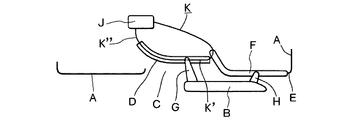
前者の場合の全体の構成関係は、図7のようになり、車体Aの側面には、スライド扉Bにより閉塞されうるドア開口Cが設けられ、ドア開口Cの下部近傍の車体AにはロワーガイドレールDが固定され、車体Aの後部側面であるクオータパネルEにはセンターガイドレールFが固定される。スライド扉Bには、ロワーガイドレールDにスライド自在に係合するロワーブラケットGと、センターガイドレールFにスライド自在に係合するセンターブラケットHとが設けられる。
動力ユニットJは、ドア開口C近傍の車体の床体に固定され、ワイヤーケーブルKの開扉用ケーブルK’は、ロワーガイドレールDの後方を経由してスライド扉BのロワーブラケットGに連結され、また、ワイヤーケーブルKの閉扉用ケーブルK”は、ロワーガイドレールDの前方を経由して、ロワーブラケットGに連結される。
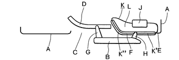
後者の場合の全体の構成関係は、図8のようになり、動力ユニットJは、クオータパネルEの内側空間Lに配置され、ワイヤーケーブルKの開扉用ケーブルK’は、センターガイドレールFの後方を経由してスライド扉BのセンターブラケットHに連結され、また、閉扉用ケーブルK”は、センターガイドレールFの前方を経由して、センターブラケットHに連結される。
The power unit can be broadly divided into a case where it is attached to a floor body in the vicinity of the door opening of the vehicle body (Japanese Utility Model Publication No. 3-76982) and a case where it is arranged in the inner space of the quarter panel of the vehicle body (Japanese Patent Laid-Open No. 9-2000). 273358).
The overall structural relationship in the former case is as shown in FIG. 7, and a door opening C that can be closed by the sliding door B is provided on the side surface of the vehicle body A. A guide rail D is fixed, and a center guide rail F is fixed to a quarter panel E which is a rear side surface of the vehicle body A. The slide door B is provided with a lower bracket G that is slidably engaged with the lower guide rail D, and a center bracket H that is slidably engaged with the center guide rail F.
The power unit J is fixed to the floor of the vehicle body in the vicinity of the door opening C, and the opening cable K ′ of the wire cable K is connected to the lower bracket G of the sliding door B via the rear of the lower guide rail D. Further, the closing cable K ″ of the wire cable K is connected to the lower bracket G via the front of the lower guide rail D.
The overall configuration relationship in the latter case is as shown in FIG. 8, the power unit J is disposed in the inner space L of the quarter panel E, and the opening cable K ′ of the wire cable K is connected to the center guide rail F. The rear door is connected to the center bracket H of the slide door B, and the closing cable K ″ is connected to the center bracket H via the front of the center guide rail F.
前記動力スライド装置には、スライド扉Bがスライド移動するときに生じるワイヤーケーブルKの配設長の変動を吸収して、ワイヤーケーブルKのテンション圧を一定に保持するテンション機構が設けられる。ガイドレールD、Fの前側部分は室内側に向かって湾曲しており、ワイヤーケーブルKの配設長は、ブラケットG、Hが湾曲部分を通過するときに最も変化する。
前記テンション機構は、通常、動力ユニットJに設けられるが、ワイヤーケーブルのケーブルエンドが連結されるブラケットG、Hに設けられることもある。
The tension mechanism is usually provided in the power unit J, but may be provided in the brackets G and H to which the cable ends of the wire cables are connected.
前記テンション機構をブラケットG、Hに設けるときの課題は、ブラケットG、Hがガイドレールの長さ方向において長くなることであり、ブラケットG、Hが長くなると、ガイドレールの両端においてスライド扉Bが移動できないデッドスペースができる。換言すれば、デッドスペースの分だけガイドレールを長くしなければならない。
また、ブラケットG、Hが湾曲部分を通過するとき、ブラケットG、Hに設けたテンション機構のケースに対してワイヤーケーブルが屈曲する課題もある。ワイヤーケーブルが屈曲すると、ワイヤーケーブルに余計な抵抗が作用してテンション機構が初期の機能を奏せなくなると共にワイヤーケーブルが傷むことになる。
A problem when the tension mechanism is provided on the brackets G and H is that the brackets G and H become longer in the length direction of the guide rail. When the brackets G and H become longer, the slide door B is formed at both ends of the guide rail. A dead space that cannot be moved is created. In other words, the guide rail must be lengthened by the amount of dead space.
Further, when the brackets G and H pass through the curved portions, there is also a problem that the wire cable is bent with respect to the case of the tension mechanism provided on the brackets G and H. If the wire cable is bent, extra resistance acts on the wire cable, and the tension mechanism cannot perform the initial function and the wire cable is damaged.
よって、本発明は、車体10に設けたガイドレールにスライド自在に取付けたスライド扉11と、モータ動力で回転するワイヤードラム26を備えた動力ユニット20と、前記スライド扉11と前記動力ユニット20とを連結するワイヤーケーブル25とからなり、前記ワイヤードラム26を回転させることで前記ワイヤーケーブル25を介して前記スライド扉11を開扉方向及び閉扉方向にスライドさせる車両スライド扉の動力スライド装置において、前記スライド扉11には前記ガイドレールにスライド自在に係合するブラケットを設け、前記動力ユニット20は前記車体10に取付け、前記ガイドレールの後部近傍には第1反転プーリー45を前部近傍には第2反転プーリー49をそれぞれ設け、前記ワイヤーケーブル25の開扉用ケーブル25’は前記動力ユニット20から後方に伸びた後前記第1反転プーリー45を経由して前方に戻してその先端は第1テンション部52に連結し、前記ワイヤーケーブル25の閉扉用ケーブル25”は前記動力ユニット20から前方に伸びた後前記第2反転プーリー49を経由して後方に戻してその先端は第2テンション部53に連結し、前記第1テンション部52と前記第2テンション部53とは互いに重なり合うように前記ブラケットに取付けた車両スライド扉用動力スライド装置のテンション機構としたものである。
Therefore, the present invention includes a
請求項1に掛かる発明では、第1テンション部52と第2テンション部53とは互いに重なり合うように前記ブラケットに取付けてあるため、テンション機構のガイドレールの長さ方向における長さを抑えることができ、従来のようなガイドレールの両端においてスライド扉Bが移動できないデッドスペースの発生を抑制できる。
また、請求項2に掛かる発明では、第1テンション部52と第2テンション部53は、ブラケットに設けたピン55、56を中心に揺動するため、ブラケットがガイドレールの湾曲部分を通過するとは、ワイヤーケーブル25の吊節方向に揺動する。このため、テンション部52、53に対してワイヤーケーブル25が屈曲することが防止され、ワイヤーケーブル25に余計な抵抗が作用したり、ワイヤーケーブル25が傷むことが抑制される。
In the invention according to claim 1, since the
In the invention according to
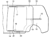
図1には、スライド扉11を備えた典型的な車体10の側面を示す。車体10の側面には、スライド扉11により閉塞されうるドア開口12が設けられ、ドア開口12の上部近傍の車体10にはアッパーガイドレール13が固定され、ドア開口12の下部近傍の車体10にはロワーガイドレール14が固定され、車体10の後部側面であるクオータパネル16にはセンターガイドレール15が固定される。スライド扉11には、アッパーガイドレール13にスライド自在に係合するアッパーブラケット17と、ロワーガイドレール14にスライド自在に係合するロワーブラケット18と、センターガイドレール15にスライド自在に係合するセンターブラケット19とが設けられる。各ブラケット17、18、19は、好適にはスライド扉11に揺動自在に軸止され、これらのブラケットとレールとの係合によりスライド扉11は車体10に開扉方向及び閉扉方向にスライド自在に取付けられる。本発明による動力スライド装置の動力ユニット20は、ドア開口12の床体21に取付けられる(クオータパネル16の室内側空間に配置してもよい)。
FIG. 1 shows a side surface of a
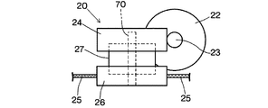
前記動力ユニット20は、図6のように、モータ22と、モータ22の出力軸に固定された円筒ウオーム23と、円筒ウオーム23に噛合するウオームホイール24と、ワイヤーケーブル25の巻取り繰出しを行うワイヤードラム26と、ウオームホイール24とワイヤードラム26との間に設けられるクラッチ機構27とから構成される。
As shown in FIG. 6, the
前記ロワーガイドレール14にスライド自在に係合させる前記ロワーブラケット18は、図3のように、スライド扉11に固定されたドアステイ28と、ドアステイ28に縦軸29で軸止されたローラープレート30とを備える。ローラープレート30には、図3、4のように、上部ローラー31が縦ローラー軸32により軸止され、また、下部ローラー33が横ローラー軸34により軸止される。
As shown in FIG. 3, the
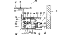
図2はドア開口12近傍の床体21と、床体21に固定される前記ロワーガイドレール14のL型プレート35とが示されている。L型プレート35の縦板部36の上部はボルト締付け又は溶接等により床体21の室内床面を構成するフロアーパネル37に固定される。縦板部36の上下の中程には、フロアーパネル37に対して階段状に一段下がった水平のステップパネル38が固定され、ステップパネル38の下面には、前記上部ローラー31がスライド自在に係合する上部ローラーガイド39が固定される。上部ローラーガイド39は、前記ロワーガイドレール14の一部を構成する。
FIG. 2 shows a
前記縦板部36の下部側はケーブルガイド面40に形成する。ケーブルガイド面40は上方視において上部ローラーガイド39と同様の形状を呈していて、前側部分には室内側に屈曲した湾曲部分41が形成され、その後方は略直線上に伸びる形状である。縦板部36の下部には、ステップパネル38に対して平行で所定間隔を置いた水平の支持面42が連設され、前記下部ローラー33は支持面42上を転動する。
A lower side of the
図2のように、前記動力ユニット20は、好適には、前記ステップパネル38上に、乗降の邪魔にならないように前後の一側に載置するか、ステップパネル38に凹部を形成して邪魔にならないように収納させる。動力ユニット20のハウジングケース43には第1プーリーケース44が一体的又は別体として設けられる。第1プーリーケース44の先端には、第1反転プーリー45が第1横プーリー軸46により軸止される。第1プーリーケース44の先端下部は、ステップパネル38の第1開口部47を介してステップパネル38より下方に突出させる。
As shown in FIG. 2, the
前記第1プーリーケース44と対をなす第2プーリーケース48は、ステップパネル38の前後の他側に配置され、第2プーリーケース48内には、第2反転プーリー49が第2横プーリー軸50により軸止される。第2プーリーケース48の下部は、ステップパネル38の第2開口部51を介してステップパネル38より下方に突出させる。
A
前記ワイヤーケーブル25は、ワイヤードラム26により巻き取られるとスライド扉11を開扉方向に引っ張る開扉用ケーブル25’と、ワイヤードラム26により巻き取られるとスライド扉11を閉扉方向に引っ張る閉扉用ケーブル25”とから構成される。開扉用ケーブル25’は前記動力ユニット20から後方に伸びた後、前記第1反転プーリー45を経由して前記ステップパネル38の下方で前方に戻され、閉扉用ケーブル25”は前記動力ユニット20から前方に伸びた後、前記第2反転プーリー49を経由して前記ステップパネル38の下方で後方に戻され、ワイヤーケーブル25は側方視において全体として環状を呈する。
When the
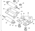
前記開扉用ケーブル25’の先端は第1テンション部52に連結され、閉扉用ケーブル25”の先端は第2テンション部53に連結される。第1及び第2テンション部52、53の先端には、テンションプレート54に植設した第1及び第2ピン55、56に係止される第1及び第2係止部57、58が設けられる。テンションプレート54に取付ける前のテンション部52、53は、図2のように、前記ステップパネル38に形成したサービスホール59を介して上方に取出して置き、サービスホール59の前後に連設させた第1及び第2仮止め溝60、61に引っ掛けておく。仮止め溝60、61は、好適には、ワイヤーケーブル25の移動方向に長い溝であり、その幅はワイヤーケーブル25よりは広いがテンション部52、53よりは狭いものとなる。
The leading end of the
前記テンションプレート54は、前記サービスホール59を通過できる大きさに形成される。仮止め溝60、61に仮止めしたテンション部52、53は、ステップパネル38の上方の広い空間でテンションプレート54に取付けた後、サービスホール59を介してテンションプレート54と共にステップパネル38の下方に戻され、その後、テンションプレート54は、ボルト62とナット63で前記ローラープレート30に取付けられる。
The
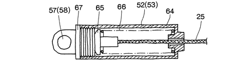
前記テンション部52、53は同一構成で、そのテンションケース64はワイヤーケーブル25の配設方向に伸びる細長い円筒形に形成され、内部にはワイヤーケーブル25のケーブルエンド65に当接するテンションバネ66が設けられる。前記係止部57、58は、テンションケース64の開口端部に螺合するケースキャップ67に設けられる。螺子式のケースキャップ67は、回転させると、テンションバネ66を圧縮させながら容易にテンションケース64に取付けられる。
The
前記テンションプレート54の前記第1ピン55は、テンションプレート54の前側に配置し、前記第2ピン56はテンションプレート54の後側に配置して、テンションプレート54に取付けられる第1テンション部52と第2テンション部53とは、上下方向において互いに重なり合うようにする。
The
図2のように、ワイヤーケーブル25のうち、前記ステップパネル38の上面に配設される部分には、弾性ケーブルシース(ケーブルアウター)68が設けられ、これにより、動力ユニット20と第2プーリーケース48との間のワイヤーケーブル25を、テンション圧に影響を与えることなく自由に配索できる。ケーブルシース68は、図3のように、ステップパネル38に形成した長い凹部69内に収納し、ステップパネル38の上面の平坦化を図っている。
As shown in FIG. 2, an elastic cable sheath (cable outer) 68 is provided in a portion of the
前記動力ユニット20のワイヤードラム26は、縦のドラム軸70を中心に回転し、ステップパネル38に対して最近接配置させる。これにより、第1反転プーリー45からワイヤードラム26に至るワイヤーケーブル25と、ワイヤードラム26のドラム軸70とを直角に近い角度に維持できる。
71は樹脂製のステップカバーである。
The
71 is a resin step cover.
(作用)
まず、ステップパネル38に第1プーリーケース44を備えた動力ユニット20及び第2プーリーケース48を取付ける。このとき、第2プーリーケース48は長い第2開口部の動力ユニット20寄りに仮止めしておく。次に、ワイヤーケーブル25の先端に取付けたテンション部52、53をステップパネル38のサービスホール59を介してステップパネル38の上方に出して仮止め溝60、61に係止させる。
(Function)
First, the
次に、仮止め溝60、61に仮止めしたテンション部52、53を、ステップパネル38の上方の広い空間で、ローラープレート30(ロワーブラケット18)に固定する前の単体のテンションプレート54に取付け、テンションプレート54及びテンション部52、53をサービスホール59を介してステップパネル38の下方に戻し、テンションプレート54をスライド扉11のドアステイ28に軸止されたローラープレート30にボルト62とナット63で固定する。
Next, the
この間、第2プーリーケース48は長い第2開口部51の動力ユニット20寄りに仮止めしてあるため、ワイヤーケーブル25は弛んでいて取付は容易となる。また、サービスホール59を介してテンションプレート54をローラープレート30に固定するから、ステップパネル38とその下部のロワーガイドレール14(支持面42)との間が狭くても、テンションプレート54をローラープレート30に固定する作業は容易に行える。
During this time, since the
テンションプレート54をローラープレート30に固定したら、仮止めしていた第2プーリーケース48を第2開口部51の反動力ユニット20側に引っ張って、ワイヤーケーブル25に適切な初期テンションを与えてから、第2プーリーケース48をステップパネル38に本固定する。
When the
このように構成された本願の動力スライド装置では、第1テンション部52と第2テンション部53とは互いに重なり合うようにテンションプレート54に取付けてあるため、テンション機構のガイドレールの長さ方向における長さは実質的に1個のテンション部の長さに抑えることができ、このため、テンション機構の長さ及びテンション機構が取付けられるテンションプレート54の長さは短くなって、ロワーガイドレール14の端から端まで最大限移動できる。
In the power slide device of the present application configured as described above, since the
また、ステップパネル38より下方に配設されたワイヤーケーブル25は、上部ローラーガイド39と同様の形状を備えたL型プレート35のケーブルガイド面40に沿って移動するが、第1テンション部52と第2テンション部53は、テンションプレート54に設けたピン55、56を中心に揺動するため、テンションプレート54がロワーガイドレール14の前側の湾曲部分41を通過するときは、テンション部52、53はワイヤーケーブル25の吊節方向に揺動し、このため、テンション部52、53に対してワイヤーケーブル25が屈曲することが防止される。
The
本願においては、ステップパネル38の前後両側に設けられた第1反転プーリー45と第2反転プーリー49は、横プーリー軸46、50を中心に回転する構造で、ワイヤーケーブル25は、ステップパネル38を上下から挟むように配置されている。このように配置すると、ワイヤーケーブル25を配設するのに必要な車両の幅方向のスペースが少なってステップパネル38の横幅を小さくでき、もって、フロアーパネル37の下方空間(ドライブシャフトや、ガソリンタンクや、エアコンダクト等の車両部品が配置される場所)への影響が抑えられる。
In the present application, the first reversing
ステップパネル38にステップカバー71を取付けると、第1プーリーケース44を備えた動力ユニット20や、第2プーリーケース48や、サービスホール59や、ケーブルシース68は隠され、また、動力ユニット20及び第2プーリーケース48は、ステップパネル38の前後の端部に配置されており、ケーブルシース68は凹部69に埋設されているため、ステップパネル38にはステップカバー71が取付けられた美麗な広いステップ面を確保できる。
When the
10…車体、11…スライド扉、12…ドア開口、13…アッパーガイドレール、14…ロワーガイドレール、15…センターガイドレール、16…クオータパネル、17…アッパーブラケット、18…ロワーブラケット、19…センターブラケット、20…動力ユニット、21…床体、22…モータ、23…円筒ウオーム、24…ウオームホイール、25…ワイヤーケーブル、25’…開扉用ケーブル、25”…閉扉用ケーブル、26…ワイヤードラム、27…クラッチ機構、28…ドアステイ、29…縦軸、30…ローラープレート、31…上部ローラー、32…縦ローラー軸、33…下部ローラー、34…縦ローラー軸、35…L型プレート、36…縦板部、37…フロアーパネル、38…ステップパネル、39…上部ローラーガイド、40…ケーブルガイド面、41…湾曲部分、42…支持面、43…ハウジングケース、44…第1プーリーケース、45…第1反転プーリー、46…第1横プーリー軸、47…第1開口部、48…第2プーリーケース、49…第2反転プーリー、50…第2横プーリー軸、51…第2開口部、52…第1テンション部、53…第2テンション部、54…テンションプレート、55…第1ピン、56…第2ピン、57…第1係止部、58…第2係止部、59…サービスホール、60…第1仮止め溝、61…第2仮止め溝、62…ボルト、63…ナット、64…テンションケース、65…ケーブルエンド、66…テンションバネ、67…ケースキャップ、68…ケーブルシース、69…凹部、70…ドラム軸、71…ステップカバー。
DESCRIPTION OF
Claims (2)
Priority Applications (3)
| Application Number | Priority Date | Filing Date | Title |
|---|---|---|---|
| JP2004103698A JP4181079B2 (en) | 2004-03-31 | 2004-03-31 | Tension mechanism of power slide device for vehicle sliding door |
| US11/094,472 US7159930B2 (en) | 2004-03-31 | 2005-03-31 | Power slide device for vehicle sliding door |
| US11/650,506 US7354100B2 (en) | 2004-03-31 | 2007-01-08 | Power slide device for vehicle sliding door |
Applications Claiming Priority (1)
| Application Number | Priority Date | Filing Date | Title |
|---|---|---|---|
| JP2004103698A JP4181079B2 (en) | 2004-03-31 | 2004-03-31 | Tension mechanism of power slide device for vehicle sliding door |
Publications (3)
| Publication Number | Publication Date |
|---|---|
| JP2005290700A true JP2005290700A (en) | 2005-10-20 |
| JP2005290700A5 JP2005290700A5 (en) | 2006-03-16 |
| JP4181079B2 JP4181079B2 (en) | 2008-11-12 |
Family
ID=35323949
Family Applications (1)
| Application Number | Title | Priority Date | Filing Date |
|---|---|---|---|
| JP2004103698A Expired - Fee Related JP4181079B2 (en) | 2004-03-31 | 2004-03-31 | Tension mechanism of power slide device for vehicle sliding door |
Country Status (1)
| Country | Link |
|---|---|
| JP (1) | JP4181079B2 (en) |
Cited By (2)
| Publication number | Priority date | Publication date | Assignee | Title |
|---|---|---|---|---|
| JP2008038403A (en) * | 2006-08-03 | 2008-02-21 | Aisin Seiki Co Ltd | Power sliding door device for vehicles |
| JP2009235891A (en) * | 2008-03-26 | 2009-10-15 | Arvinmeritor Light Vehicle Systems-France | Sliding door carriage, sliding door driving system, vehicle and method of mounting sliding door driving system |
Families Citing this family (2)
| Publication number | Priority date | Publication date | Assignee | Title |
|---|---|---|---|---|
| JP5712952B2 (en) | 2012-03-01 | 2015-05-07 | アイシン精機株式会社 | Vehicle door opening and closing device |
| JP2015224531A (en) * | 2014-05-30 | 2015-12-14 | アイシン精機株式会社 | Guide roller unit and vehicle slide door device |
-
2004
- 2004-03-31 JP JP2004103698A patent/JP4181079B2/en not_active Expired - Fee Related
Cited By (2)
| Publication number | Priority date | Publication date | Assignee | Title |
|---|---|---|---|---|
| JP2008038403A (en) * | 2006-08-03 | 2008-02-21 | Aisin Seiki Co Ltd | Power sliding door device for vehicles |
| JP2009235891A (en) * | 2008-03-26 | 2009-10-15 | Arvinmeritor Light Vehicle Systems-France | Sliding door carriage, sliding door driving system, vehicle and method of mounting sliding door driving system |
Also Published As
| Publication number | Publication date |
|---|---|
| JP4181079B2 (en) | 2008-11-12 |
Similar Documents
| Publication | Publication Date | Title |
|---|---|---|
| US7354100B2 (en) | Power slide device for vehicle sliding door | |
| JP5796238B2 (en) | Opening and closing device for vehicle door | |
| JP5993593B2 (en) | Sunshade equipment | |
| CN105452032B (en) | Device for opening/closing door | |
| WO2013129206A1 (en) | Vehicle door opening/closing device | |
| DE602004032080D1 (en) | Opening and closing device for motor vehicle sliding doors | |
| JP2009102958A (en) | Swing slide door opening and closing device | |
| CN105492228A (en) | door opening and closing device | |
| JP4181079B2 (en) | Tension mechanism of power slide device for vehicle sliding door | |
| JP2006009350A (en) | Roller arm unit for vehicle sliding door | |
| JP2002309851A (en) | Drive unit for automotive sliding door | |
| JP4034750B2 (en) | Connecting structure and connecting method of wire cable of power slide device | |
| JP4492550B2 (en) | Swing slide door routing structure | |
| JP6164654B2 (en) | Feed structure for slide structure | |
| JP2012131457A (en) | Device for opening and closing slide door | |
| JP4183650B2 (en) | Power sliding device for sliding door | |
| JP5799582B2 (en) | Vehicle door opening / closing device and method for manufacturing vehicle door opening / closing device | |
| JP7077855B2 (en) | Sliding door device for vehicles | |
| JP2008125252A (en) | Power feeding device for slide structure | |
| JP5796239B2 (en) | Opening and closing device for vehicle door | |
| JP2009013669A (en) | Window regulator | |
| JP5001188B2 (en) | slide door | |
| JP3995675B2 (en) | Roller arm unit for vehicle sliding door | |
| JP5654777B2 (en) | Automatic sliding door opening / closing device | |
| JP2007278000A (en) | Carrier plate and window regulator provided with the same |
Legal Events
| Date | Code | Title | Description |
|---|---|---|---|
| A621 | Written request for application examination |
Free format text: JAPANESE INTERMEDIATE CODE: A621 Effective date: 20051121 |
|
| A521 | Request for written amendment filed |
Free format text: JAPANESE INTERMEDIATE CODE: A523 Effective date: 20060127 |
|
| A711 | Notification of change in applicant |
Free format text: JAPANESE INTERMEDIATE CODE: A711 Effective date: 20061227 |
|
| A521 | Request for written amendment filed |
Free format text: JAPANESE INTERMEDIATE CODE: A821 Effective date: 20061227 |
|
| A521 | Request for written amendment filed |
Free format text: JAPANESE INTERMEDIATE CODE: A523 Effective date: 20070625 |
|
| A521 | Request for written amendment filed |
Free format text: JAPANESE INTERMEDIATE CODE: A821 Effective date: 20070625 |
|
| A977 | Report on retrieval |
Free format text: JAPANESE INTERMEDIATE CODE: A971007 Effective date: 20071004 |
|
| A131 | Notification of reasons for refusal |
Free format text: JAPANESE INTERMEDIATE CODE: A131 Effective date: 20071016 |
|
| A521 | Request for written amendment filed |
Free format text: JAPANESE INTERMEDIATE CODE: A523 Effective date: 20071120 |
|
| TRDD | Decision of grant or rejection written | ||
| A01 | Written decision to grant a patent or to grant a registration (utility model) |
Free format text: JAPANESE INTERMEDIATE CODE: A01 Effective date: 20080819 |
|
| A01 | Written decision to grant a patent or to grant a registration (utility model) |
Free format text: JAPANESE INTERMEDIATE CODE: A01 |
|
| A61 | First payment of annual fees (during grant procedure) |
Free format text: JAPANESE INTERMEDIATE CODE: A61 Effective date: 20080828 |
|
| R150 | Certificate of patent or registration of utility model |
Ref document number: 4181079 Country of ref document: JP Free format text: JAPANESE INTERMEDIATE CODE: R150 Free format text: JAPANESE INTERMEDIATE CODE: R150 |
|
| FPAY | Renewal fee payment (event date is renewal date of database) |
Free format text: PAYMENT UNTIL: 20110905 Year of fee payment: 3 |
|
| S111 | Request for change of ownership or part of ownership |
Free format text: JAPANESE INTERMEDIATE CODE: R313117 |
|
| FPAY | Renewal fee payment (event date is renewal date of database) |
Free format text: PAYMENT UNTIL: 20110905 Year of fee payment: 3 |
|
| R350 | Written notification of registration of transfer |
Free format text: JAPANESE INTERMEDIATE CODE: R350 |
|
| FPAY | Renewal fee payment (event date is renewal date of database) |
Free format text: PAYMENT UNTIL: 20120905 Year of fee payment: 4 |
|
| FPAY | Renewal fee payment (event date is renewal date of database) |
Free format text: PAYMENT UNTIL: 20130905 Year of fee payment: 5 |
|
| R250 | Receipt of annual fees |
Free format text: JAPANESE INTERMEDIATE CODE: R250 |
|
| FPAY | Renewal fee payment (event date is renewal date of database) |
Free format text: PAYMENT UNTIL: 20140905 Year of fee payment: 6 |
|
| R250 | Receipt of annual fees |
Free format text: JAPANESE INTERMEDIATE CODE: R250 |
|
| R250 | Receipt of annual fees |
Free format text: JAPANESE INTERMEDIATE CODE: R250 |
|
| R250 | Receipt of annual fees |
Free format text: JAPANESE INTERMEDIATE CODE: R250 |
|
| R250 | Receipt of annual fees |
Free format text: JAPANESE INTERMEDIATE CODE: R250 |
|
| R250 | Receipt of annual fees |
Free format text: JAPANESE INTERMEDIATE CODE: R250 |
|
| R250 | Receipt of annual fees |
Free format text: JAPANESE INTERMEDIATE CODE: R250 |
|
| R250 | Receipt of annual fees |
Free format text: JAPANESE INTERMEDIATE CODE: R250 |
|
| R250 | Receipt of annual fees |
Free format text: JAPANESE INTERMEDIATE CODE: R250 |
|
| R250 | Receipt of annual fees |
Free format text: JAPANESE INTERMEDIATE CODE: R250 |
|
| R250 | Receipt of annual fees |
Free format text: JAPANESE INTERMEDIATE CODE: R250 |
|
| LAPS | Cancellation because of no payment of annual fees |