JP4034750B2 - Connecting structure and connecting method of wire cable of power slide device - Google Patents

Connecting structure and connecting method of wire cable of power slide device Download PDF

Info

Publication number
JP4034750B2
JP4034750B2 JP2004103699A JP2004103699A JP4034750B2 JP 4034750 B2 JP4034750 B2 JP 4034750B2 JP 2004103699 A JP2004103699 A JP 2004103699A JP 2004103699 A JP2004103699 A JP 2004103699A JP 4034750 B2 JP4034750 B2 JP 4034750B2
Authority
JP
Japan
Prior art keywords
cable
step panel
surface side
plate
door
Prior art date
Legal status (The legal status is an assumption and is not a legal conclusion. Google has not performed a legal analysis and makes no representation as to the accuracy of the status listed.)
Expired - Fee Related
Application number
JP2004103699A
Other languages
Japanese (ja)
Other versions
JP2005290701A5 (en
JP2005290701A (en
Inventor
和人 横森
洋 佐藤
Current Assignee (The listed assignees may be inaccurate. Google has not performed a legal analysis and makes no representation or warranty as to the accuracy of the list.)
Mitsui Mining and Smelting Co Ltd
Original Assignee
Mitsui Mining and Smelting Co Ltd
Priority date (The priority date is an assumption and is not a legal conclusion. Google has not performed a legal analysis and makes no representation as to the accuracy of the date listed.)
Filing date
Publication date
Application filed by Mitsui Mining and Smelting Co Ltd filed Critical Mitsui Mining and Smelting Co Ltd
Priority to JP2004103699A priority Critical patent/JP4034750B2/en
Priority to US11/094,472 priority patent/US7159930B2/en
Publication of JP2005290701A publication Critical patent/JP2005290701A/en
Publication of JP2005290701A5 publication Critical patent/JP2005290701A5/ja
Priority to US11/650,506 priority patent/US7354100B2/en
Application granted granted Critical
Publication of JP4034750B2 publication Critical patent/JP4034750B2/en
Anticipated expiration legal-status Critical
Expired - Fee Related legal-status Critical Current

Links

Images

Description

本発明は、車両スライド扉用動力スライド装置のワイヤーケーブルの連結構造及び連結方法に関するものである。   The present invention relates to a wire cable connection structure and a connection method of a power slide device for a vehicle sliding door.

従来、車体に設けた複数のガイドレールにスライド自在に取付けたスライド扉と、モータ動力で回転するワイヤードラムを備えた動力ユニットと、スライド扉と動力ユニットとを連結するワイヤーケーブルとからなり、ワイヤードラムを回転させることでワイヤーケーブルを介してスライド扉を開扉方向及び閉扉方向にスライドさせる車両スライド扉の動力スライド装置は、公知である。   Conventionally, it consists of a sliding door slidably attached to a plurality of guide rails provided on the vehicle body, a power unit having a wire drum that rotates by motor power, and a wire cable that connects the sliding door and the power unit. A power slide device for a vehicle slide door that slides a slide door in a door opening direction and a door closing direction via a wire cable by rotating a drum is known.

前記動力ユニットは、大別すると、車体のドア開口部近傍の床体に取付けられる場合(実開平3−76982号公報)と、車体のクオータパネルの内側空間に配置される場合(特開平9−273358号公報)とがある。
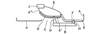
前者の場合の全体の構成関係は、図7のようになり、車体Aの側面には、スライド扉Bにより閉塞されうるドア開口Cが設けられ、ドア開口Cの下部近傍の車体AにはロワーガイドレールDが固定され、車体Aの後部側面であるクオータパネルEにはセンターガイドレールFが固定される。スライド扉Bには、ロワーガイドレールDにスライド自在に係合するロワーブラケットGと、センターガイドレールFにスライド自在に係合するセンターブラケットHとが設けられる。
The power unit can be broadly divided into a case where the power unit is attached to a floor near the door opening of the vehicle body (Japanese Utility Model Laid-Open No. 3-76982) and a case where the power unit is disposed in the inner space of the quarter panel of the vehicle body (Japanese Patent Laid-Open No. 9-2000). 273358).
The overall structural relationship in the former case is as shown in FIG. 7, and a door opening C that can be closed by the sliding door B is provided on the side surface of the vehicle body A. A guide rail D is fixed, and a center guide rail F is fixed to a quarter panel E which is a rear side surface of the vehicle body A. The slide door B is provided with a lower bracket G that is slidably engaged with the lower guide rail D, and a center bracket H that is slidably engaged with the center guide rail F.

動力ユニットJは、ドア開口C近傍の車体の床体に固定され、ワイヤーケーブルKの開扉用ケーブルK’は、ロワーガイドレールDの後方を経由してスライド扉BのロワーブラケットGに連結され、また、ワイヤーケーブルKの閉扉用ケーブルK”は、ロワーガイドレールDの前方を経由して、ロワーブラケットGに連結される。
また、前記動力スライド装置には、スライド扉Bがスライド移動するときに生じるワイヤーケーブルKの配設長の変動を吸収して、ワイヤーケーブルKのテンション圧を一定に保持するテンション機構が設けられる。このテンション機構は動力ユニットJ又はロワーブラケットGに設けられる。
実開平3−76982号公報 特開平9−273358号公報
The power unit J is fixed to the floor of the vehicle body in the vicinity of the door opening C, and the opening cable K ′ of the wire cable K is connected to the lower bracket G of the sliding door B via the rear of the lower guide rail D. Further, the closing cable K ″ of the wire cable K is connected to the lower bracket G via the front of the lower guide rail D.
In addition, the power slide device is provided with a tension mechanism that absorbs fluctuations in the arrangement length of the wire cable K that occurs when the slide door B slides and keeps the tension pressure of the wire cable K constant. This tension mechanism is provided in the power unit J or the lower bracket G.
Japanese Utility Model Publication No. 3-76982 Japanese Patent Laid-Open No. 9-273358

前記公知例では、ワイヤーケーブルKの両端をロワーブラケットGに連結する作業が非常に面倒になっていた。つまり、ロワーガイドレールDにスライド自在に係合させた後のロワーブラケットGは、簡単には手が届かない位置にあって取り付け作業に熟練度が必要であった。
また、前記ワイヤーケーブルKのテンション機構は、動力ユニットJの小型化等の目的でロワーブラケットGに設ける場合があるが、テンション機構をロワーブラケットGに設けるときには、更に取付作業が面倒になり課題があった。
In the known example, the operation of connecting both ends of the wire cable K to the lower bracket G is very troublesome. That is, the lower bracket G after being slidably engaged with the lower guide rail D is in a position where it cannot be easily reached, and requires a certain level of skill in the mounting operation.
Further, the tension mechanism of the wire cable K may be provided on the lower bracket G for the purpose of reducing the size of the power unit J. However, when the tension mechanism is provided on the lower bracket G, the installation work becomes more troublesome and there is a problem. there were.

よって、本発明は、スライド扉11のロワーブラケット18を車体10に設けたロワーガイドレール14にスライド自在に取付け、モータ動力で回転するワイヤードラム26を備えた動力ユニット20を前記車体10の床体21に固定し、前記ロワーガイドレール14の後部近傍には第1反転プーリー45を前部近傍には第2反転プーリー49をそれぞれ設け、前記ワイヤードラム26にはワイヤーケーブル25の開扉用ケーブル25’及び閉扉用ケーブル25”の各基端側を連結し、前記開扉用ケーブル25’の先端側ケーブルエンドは前記動力ユニット20から後方に伸ばした後前記第1反転プーリー45を経由させて前方に戻して前記ロワーブラケット18に連結し、前記閉扉用ケーブル25”の先端側ケーブルエンドは前記動力ユニット20から前方に伸ばした後前記第2反転プーリー49を経由させて後方に戻して前記ロワーブラケット18に連結した車両スライド扉の動力スライド装置において、前記ロワーガイドレール14は前記床体21のステップパネル38の下方に配置し、前記ワイヤーケーブル25は前記ステップパネル38を上下から囲うように配索し、前記ステップパネル38にはサービスホール59を設け、前記開扉用ケーブル25’及び前記閉扉用ケーブル25”の前記各ケーブルエンドは前記サービスホール59を通過できる大きさのプレート54に連結させ、前記プレート54は前記サービスホール59を介して前記ステップパネル38の下方に移動させた状態で前記ロワーブラケット18に固定する動力スライド装置のワイヤーケーブルの連結構造としたものである。
また、本発明は、ステップパネル38の上面側で動力ユニット20から後方に伸ばしたワイヤーケーブル25の開扉用ケーブル25’を第1反転プーリー45により前記ステップパネル38の下面側に降ろし、前記ステップパネル38の上面側で前記動力ユニット20から前方に伸ばした前記ワイヤーケーブル25の閉扉用ケーブル25”を第2反転プーリー49により前記ステップパネル38の下面側に降ろし、前記ステップパネル38の下面側に降ろした前記開扉用ケーブル25’の先端側は前記ステップパネル38の下部に設けたロワーガイドレール14と前記ステップパネル38との間を前方に伸ばした後前記ステップパネル38に形成したサービスホール59を介して前記ステップパネル38の上面側に引出し、前記ステップパネル38の下面側に降ろした前記閉扉用ケーブル25”の先端側は前記ステップパネル38と前記ロワーガイドレール14との間を後方に伸ばした後前記サービスホール59を介して前記ステップパネル38の上面側に引出し、前記サービスホール59から上方に引き出した前記ケーブル25’、25”の前記先端側は前記ステップパネル38の上面側でプレート54に連結させ、前記ケーブル25’、25”を連結した前記プレート54は前記サービスホール59を介して前記ステップパネル38の下面側に移動させた後スライド扉11のロワーブラケット18に固定する動力スライド装置のワイヤーケーブルの連結方法としたものである。
Therefore, in the present invention, the lower bracket 18 of the sliding door 11 is slidably attached to the lower guide rail 14 provided on the vehicle body 10, and the power unit 20 including the wire drum 26 that rotates by motor power is attached to the floor body of the vehicle body 10. 21, a first reversing pulley 45 is provided in the vicinity of the rear part of the lower guide rail 14, and a second reversing pulley 49 is provided in the vicinity of the front part. The wire drum 26 has a door opening cable 25. 'And the door closing cable 25 "are connected to each proximal end, and the front end cable end of the door opening cable 25' extends rearward from the power unit 20 and then forwards via the first reversing pulley 45. And connected to the lower bracket 18, and the cable end of the door closing cable 25 "is connected to the power unit. In the power sliding device for a vehicle sliding door which extends forward from 20 and then returns to the rear via the second reversing pulley 49 and is connected to the lower bracket 18, the lower guide rail 14 is a step panel of the floor body 21. 38, the wire cable 25 is routed so as to surround the step panel 38 from above and below, the service hole 59 is provided in the step panel 38, the opening cable 25 'and the closing cable Each cable end 25 ″ is connected to a plate 54 sized to pass through the service hole 59, and the plate 54 is moved below the step panel 38 through the service hole 59. Connection structure of wire cable of power slide device fixed to 18 One in which the.
In the present invention, the door opening cable 25 ′ of the wire cable 25 extending rearward from the power unit 20 on the upper surface side of the step panel 38 is lowered to the lower surface side of the step panel 38 by the first reversing pulley 45. The closing cable 25 ″ of the wire cable 25 extending forward from the power unit 20 on the upper surface side of the panel 38 is lowered to the lower surface side of the step panel 38 by the second reversing pulley 49, and is moved to the lower surface side of the step panel 38. A service hole 59 formed in the step panel 38 after the front end side of the lowered door opening cable 25 ′ extends forward between the lower guide rail 14 provided at the lower portion of the step panel 38 and the step panel 38. Through the step panel 38 to the upper surface side, the step panel The front end side of the door closing cable 25 ″ lowered to the lower surface side of FIG. 8 extends rearward between the step panel 38 and the lower guide rail 14 and then the upper surface side of the step panel 38 through the service hole 59. The front ends of the cables 25 ′ and 25 ″ drawn upward from the service hole 59 are connected to the plate 54 on the upper surface side of the step panel 38, and the cables 25 ′ and 25 ″ are connected to the plate. 54 is a method of connecting a wire cable of a power slide device that is moved to the lower surface side of the step panel 38 through the service hole 59 and then fixed to the lower bracket 18 of the slide door 11.

本願請求項1に掛かる発明では、ステップパネル38の上方の広い空間でワイヤーケーブル25の各ケーブルエンド65をプレート54に取付けることができ、プレート54は前記サービスホール59を介して前記ステップパネル38の下方に移動させた状態で前記ロワーブラケット18に固定できるので、ケーブルエンド65とプレート54との連結及びプレート54とロワーブラケット18との固定の双方とも従来に比べて格段に容易となる。
また、本願請求項2に掛かる発明では、サービルホール59に連設させた仮止め溝60、61により各ケーブルエンド65を前記ステップパネル38の上面側に露出状態で保持できるので、更に取付作業が楽になる。
また、本願請求項3に掛かる発明では、テンション機構をロワーブラケット18側に設けるときも、取付作業の容易化が図れる。
また、本願請求項4に掛かる発明では、ステップパネル38の上方の広い空間でワイヤーケーブル25の各ケーブルエンド65をプレート54に取付けることができ、プレート54は前記サービスホール59を介して前記ステップパネル38の下方に移動させた状態で前記ロワーブラケット18に固定できるので、ケーブルエンド65とプレート54との連結及びプレート54とロワーブラケット18との固定の双方とも従来に比べて格段に容易となる。
また、本願請求項5に掛かる発明では、サービルホール59に連設させた仮止め溝60、61により各ケーブルエンド65を前記ステップパネル38の上面側に露出状態で保持できるので、更に取付作業が楽になる。
また、本願請求項6に掛かる発明では、テンション機構をロワーブラケット18側に設けるときも、取付作業の容易化が図れる。
In the invention according to claim 1 of the present application, each cable end 65 of the wire cable 25 can be attached to the plate 54 in a wide space above the step panel 38, and the plate 54 can be attached to the step panel 38 via the service hole 59. Since it can be fixed to the lower bracket 18 in a state of being moved downward, both the connection between the cable end 65 and the plate 54 and the fixation between the plate 54 and the lower bracket 18 are much easier than in the prior art.
Further, in the invention according to claim 2 of the present application, each cable end 65 can be held in an exposed state on the upper surface side of the step panel 38 by the temporary fixing grooves 60 and 61 continuously provided in the service hall 59, so that the mounting work can be further performed. It will be easy.
In the invention according to claim 3 of the present application, when the tension mechanism is provided on the lower bracket 18 side, the mounting work can be facilitated.
In the invention according to claim 4, each cable end 65 of the wire cable 25 can be attached to the plate 54 in a wide space above the step panel 38, and the plate 54 is connected to the step panel via the service hole 59. Since it can be fixed to the lower bracket 18 in a state of being moved below the position 38, both the connection between the cable end 65 and the plate 54 and the fixation between the plate 54 and the lower bracket 18 are much easier than in the prior art.
Further, in the invention according to claim 5 of the present application, each cable end 65 can be held in an exposed state on the upper surface side of the step panel 38 by the temporary fixing grooves 60, 61 continuously provided in the service hall 59. It will be easy.
In the invention according to claim 6 of the present application, when the tension mechanism is provided on the lower bracket 18 side, the mounting work can be facilitated.

図1には、スライド扉11を備えた典型的な車体10の側面を示す。車体10の側面には、スライド扉11により閉塞されうるドア開口12が設けられ、ドア開口12の上部近傍の車体10にはアッパーガイドレール13が固定され、ドア開口12の下部近傍の車体10にはロワーガイドレール14が固定され、車体10の後部側面であるクオータパネル16にはセンターガイドレール15が固定される。スライド扉11には、アッパーガイドレール13にスライド自在に係合するアッパーブラケット17と、ロワーガイドレール14にスライド自在に係合するロワーブラケット18と、センターガイドレール15にスライド自在に係合するセンターブラケット19とが設けられる。各ブラケット17、18、19は、好適にはスライド扉11に揺動自在に軸止され、これらのブラケットとレールとの係合によりスライド扉11は車体10に開扉方向及び閉扉方向にスライド自在に取付けられる。本発明による動力スライド装置の動力ユニット20は、ドア開口12の床体21に取付けられる。   FIG. 1 shows a side surface of a typical vehicle body 10 provided with a sliding door 11. A door opening 12 that can be closed by a sliding door 11 is provided on a side surface of the vehicle body 10, and an upper guide rail 13 is fixed to the vehicle body 10 near the upper portion of the door opening 12. The lower guide rail 14 is fixed, and the center guide rail 15 is fixed to the quarter panel 16 which is the rear side surface of the vehicle body 10. The slide door 11 includes an upper bracket 17 slidably engaged with the upper guide rail 13, a lower bracket 18 slidably engaged with the lower guide rail 14, and a center slidably engaged with the center guide rail 15. A bracket 19 is provided. Each bracket 17, 18, 19 is preferably pivotally fixed to the slide door 11, and the slide door 11 is slidable in the door opening direction and the door closing direction with respect to the vehicle body 10 by the engagement between the bracket and the rail. Mounted on. The power unit 20 of the power slide device according to the present invention is attached to the floor body 21 of the door opening 12.

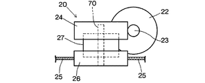
前記動力ユニット20は、図6のように、モータ22と、モータ22の出力軸に固定された円筒ウオーム23と、円筒ウオーム23に噛合するウオームホイール24と、ワイヤーケーブル25の巻取り繰出しを行うワイヤードラム26と、ウオームホイール24とワイヤードラム26との間に設けられるクラッチ機構27とから構成される。   As shown in FIG. 6, the power unit 20 performs winding and unwinding of a motor 22, a cylindrical worm 23 fixed to the output shaft of the motor 22, a worm wheel 24 meshing with the cylindrical worm 23, and a wire cable 25. It comprises a wire drum 26 and a clutch mechanism 27 provided between the worm wheel 24 and the wire drum 26.

前記ロワーガイドレール14にスライド自在に係合させる前記ロワーブラケット18は、図3のように、スライド扉11に固定されたドアステイ28と、ドアステイ28に縦軸29で軸止されたローラープレート30とを備える。ローラープレート30には、図3、4のように、上部ローラー31が縦ローラー軸32により軸止され、また、下部ローラー33が横ローラー軸34により軸止される。   As shown in FIG. 3, the lower bracket 18 slidably engaged with the lower guide rail 14 includes a door stay 28 fixed to the slide door 11, and a roller plate 30 fixed to the door stay 28 with a vertical axis 29. Is provided. As shown in FIGS. 3 and 4, the upper roller 31 is fixed to the roller plate 30 by the vertical roller shaft 32, and the lower roller 33 is fixed by the horizontal roller shaft 34.

図2はドア開口12近傍の床体21と、床体21に固定される前記ロワーガイドレール14のL型プレート35とが示されている。L型プレート35の縦板部36の上部はボルト締付け又は溶接等により床体21の室内床面を構成するフロアーパネル37に固定される。縦板部36の上下の中程には、フロアーパネル37に対して階段状に一段下がった水平のステップパネル38が固定され、ステップパネル38の下面には、前記上部ローラー31がスライド自在に係合する上部ローラーガイド39が固定される。上部ローラーガイド39は、前記ロワーガイドレール14の一部を構成する。   FIG. 2 shows a floor 21 near the door opening 12 and an L-shaped plate 35 of the lower guide rail 14 fixed to the floor 21. The upper part of the vertical plate portion 36 of the L-shaped plate 35 is fixed to a floor panel 37 constituting the indoor floor surface of the floor body 21 by bolting or welding. A horizontal step panel 38 that is stepped down with respect to the floor panel 37 is fixed in the middle of the upper and lower portions of the vertical plate portion 36, and the upper roller 31 is slidably engaged with the lower surface of the step panel 38. The upper roller guide 39 to be joined is fixed. The upper roller guide 39 constitutes a part of the lower guide rail 14.

前記縦板部36の下部側はケーブルガイド面40に形成する。ケーブルガイド面40は上方視において上部ローラーガイド39と同様の形状を呈していて、前側部分には室内側に屈曲した湾曲部分41が形成され、その後方は略直線上に伸びる形状である。縦板部36の下部には、ステップパネル38に対して平行で所定間隔を置いた水平の支持面42が連設され、前記下部ローラー33は支持面42上を転動する。   A lower side of the vertical plate portion 36 is formed on the cable guide surface 40. The cable guide surface 40 has a shape similar to that of the upper roller guide 39 as viewed from above, and a curved portion 41 bent toward the indoor side is formed on the front side portion, and the rear side thereof has a shape extending substantially linearly. A horizontal support surface 42 that is parallel to the step panel 38 and spaced at a predetermined interval is connected to the lower portion of the vertical plate portion 36, and the lower roller 33 rolls on the support surface 42.

図2のように、前記動力ユニット20は、好適には、前記ステップパネル38上に、乗降の邪魔にならないように前後の一側に載置するか、ステップパネル38に凹部を形成して邪魔にならないように収納させる。動力ユニット20のハウジングケース43には第1プーリーケース44が一体的又は別体として設けられる。第1プーリーケース44の先端には、第1反転プーリー45が第1横プーリー軸46により軸止される。第1プーリーケース44の先端下部は、ステップパネル38の第1開口部47を介してステップパネル38より下方に突出させる。   As shown in FIG. 2, the power unit 20 is preferably placed on the step panel 38 on one side of the front and back so as not to obstruct getting on or off, or a recess is formed on the step panel 38 to obstruct the operation. Store it so that it does not become. A first pulley case 44 is integrally or separately provided on the housing case 43 of the power unit 20. A first reversing pulley 45 is fixed to the front end of the first pulley case 44 by a first horizontal pulley shaft 46. The lower end of the first pulley case 44 protrudes downward from the step panel 38 through the first opening 47 of the step panel 38.

前記第1プーリーケース44と対をなす第2プーリーケース48は、ステップパネル38の前後の他側に配置され、第2プーリーケース48内には、第2反転プーリー49が第2横プーリー軸50により軸止される。第2プーリーケース48の下部は、ステップパネル38の第2開口部51を介してステップパネル38より下方に突出させる。   A second pulley case 48 that forms a pair with the first pulley case 44 is disposed on the other side of the front and rear of the step panel 38, and in the second pulley case 48, a second reversing pulley 49 is disposed on the second lateral pulley shaft 50. It is fixed by the shaft. The lower portion of the second pulley case 48 is protruded downward from the step panel 38 through the second opening 51 of the step panel 38.

前記ワイヤーケーブル25は、ワイヤードラム26により巻き取られるとスライド扉11を開扉方向に引っ張る開扉用ケーブル25’と、ワイヤードラム26により巻き取られるとスライド扉11を閉扉方向に引っ張る閉扉用ケーブル25”とから構成される。開扉用ケーブル25’は前記動力ユニット20から後方に伸びた後、前記第1反転プーリー45を経由して前記ステップパネル38の下方で前方に戻され、閉扉用ケーブル25”は前記動力ユニット20から前方に伸びた後、前記第2反転プーリー49を経由して前記ステップパネル38の下方で後方に戻され、ワイヤーケーブル25は側方視において全体として環状を呈する。   When the wire cable 25 is wound around the wire drum 26, the opening cable 25 'pulls the sliding door 11 in the opening direction. When the wire cable 25 is wound around the wire drum 26, the closing cable pulls the sliding door 11 in the closing direction. The door opening cable 25 ′ extends rearward from the power unit 20 and then returns to the front under the step panel 38 via the first reversing pulley 45 to close the door. The cable 25 "extends forward from the power unit 20, and then returns to the rear under the step panel 38 via the second reversing pulley 49. The wire cable 25 has an annular shape as a whole when viewed laterally. .

前記開扉用ケーブル25’の先端は第1テンション部52に連結され、閉扉用ケーブル25”の先端は第2テンション部53に連結される。第1及び第2テンション部52、53の先端には、テンションプレート54に植設した第1及び第2ピン55、56に係止される第1及び第2係止部57、58が設けられる。テンションプレート54に取付ける前のテンション部52、53は、図2のように、前記ステップパネル38に形成したサービスホール59を介して上方に取出して置き、サービスホール59の前後に連設させた第1及び第2仮止め溝60、61に引っ掛けておく。仮止め溝60、61は、好適には、ワイヤーケーブル25の移動方向に長い溝であり、その幅はワイヤーケーブル25よりは広いがテンション部52、53よりは狭いものとなる。   The leading end of the opening cable 25 ′ is connected to the first tension part 52, and the leading end of the closing cable 25 ″ is connected to the second tension part 53. The leading ends of the first and second tension parts 52, 53 are connected. Are provided with first and second locking portions 57 and 58 which are locked to first and second pins 55 and 56 implanted in the tension plate 54. Tension portions 52 and 53 before being attached to the tension plate 54. As shown in FIG. 2, it is taken out through the service hole 59 formed in the step panel 38 and placed and hooked into the first and second temporary fixing grooves 60, 61 connected in front of and behind the service hole 59. The temporary fixing grooves 60 and 61 are preferably grooves that are long in the moving direction of the wire cable 25, and the width thereof is wider than that of the wire cable 25 but from the tension portions 52 and 53. The narrow ones.

前記テンションプレート54は、前記サービスホール59を通過できる大きさに形成される。仮止め溝60、61に仮止めしたテンション部52、53は、ステップパネル38の上方の広い空間でテンションプレート54に取付けた後、サービスホール59を介してテンションプレート54と共にステップパネル38の下方に戻され、その後、テンションプレート54は、ボルト62とナット63で前記ローラープレート30に取付けられる。   The tension plate 54 is sized to pass through the service hole 59. The tension portions 52 and 53 temporarily fixed in the temporary fixing grooves 60 and 61 are attached to the tension plate 54 in a wide space above the step panel 38 and then below the step panel 38 together with the tension plate 54 through the service hole 59. Then, the tension plate 54 is attached to the roller plate 30 with bolts 62 and nuts 63.

前記テンション部52、53は同一構成で、そのテンションケース64はワイヤーケーブル25の配設方向に伸びる細長い円筒形に形成され、内部にはワイヤーケーブル25のケーブルエンド65に当接するテンションバネ66が設けられる。前記係止部57、58は、テンションケース64の開口端部に螺合するケースキャップ67に設けられる。螺子式のケースキャップ67は、回転させると、テンションバネ66を圧縮させながら容易にテンションケース64に取付けられる。   The tension portions 52 and 53 have the same configuration, and the tension case 64 is formed in an elongated cylindrical shape extending in the direction in which the wire cable 25 is disposed, and a tension spring 66 that contacts the cable end 65 of the wire cable 25 is provided inside. It is done. The locking portions 57 and 58 are provided on a case cap 67 that is screwed into the opening end of the tension case 64. When the screw-type case cap 67 is rotated, it is easily attached to the tension case 64 while compressing the tension spring 66.

前記テンションプレート54の前記第1ピン55は、テンションプレート54の前側に配置し、前記第2ピン56はテンションプレート54の後側に配置して、テンションプレート54に取付けられる第1テンション部52と第2テンション部53とは、上下方向において互いに重なり合うようにする。   The first pin 55 of the tension plate 54 is disposed on the front side of the tension plate 54, and the second pin 56 is disposed on the rear side of the tension plate 54, and the first tension part 52 attached to the tension plate 54 and The second tension part 53 overlaps with each other in the vertical direction.

図2のように、ワイヤーケーブル25のうち、前記ステップパネル38の上面に配設される部分には、弾性ケーブルシース(ケーブルアウター)68が設けられ、これにより、動力ユニット20と第2プーリーケース48との間のワイヤーケーブル25を、テンション圧に影響を与えることなく自由に配索できる。ケーブルシース68は、図3のように、ステップパネル38に形成した長い凹部69内に収納し、ステップパネル38の上面の平坦化を図っている。   As shown in FIG. 2, an elastic cable sheath (cable outer) 68 is provided in a portion of the wire cable 25 disposed on the upper surface of the step panel 38, whereby the power unit 20 and the second pulley case are provided. The wire cable 25 between 48 can be routed freely without affecting the tension pressure. As shown in FIG. 3, the cable sheath 68 is housed in a long recess 69 formed in the step panel 38 so that the upper surface of the step panel 38 is flattened.

前記動力ユニット20のワイヤードラム26は、縦のドラム軸70を中心に回転し、ステップパネル38に対して最近接配置させる。これにより、第1反転プーリー45からワイヤードラム26に至るワイヤーケーブル25と、ワイヤードラム26のドラム軸70とを直角に近い角度に維持できる。
71は樹脂製のステップカバーである。
The wire drum 26 of the power unit 20 rotates around a vertical drum shaft 70 and is disposed closest to the step panel 38. Thereby, the wire cable 25 extending from the first reversing pulley 45 to the wire drum 26 and the drum shaft 70 of the wire drum 26 can be maintained at an angle close to a right angle.
71 is a resin step cover.

(作用)
まず、ステップパネル38に第1プーリーケース44を備えた動力ユニット20及び第2プーリーケース48を取付ける。このとき、第2プーリーケース48は長い第2開口部の動力ユニット20寄りに仮止めしておく。次に、ワイヤーケーブル25の先端に取付けたテンション部52、53をステップパネル38のサービスホール59を介してステップパネル38の上方に出して仮止め溝60、61に係止させる。
(Function)
First, the power unit 20 including the first pulley case 44 and the second pulley case 48 are attached to the step panel 38. At this time, the second pulley case 48 is temporarily fixed near the power unit 20 of the long second opening. Next, the tension portions 52 and 53 attached to the tip end of the wire cable 25 are taken out above the step panel 38 through the service hole 59 of the step panel 38 and locked in the temporary fixing grooves 60 and 61.

次に、仮止め溝60、61に仮止めしたテンション部52、53を、ステップパネル38の上方の広い空間で、ローラープレート30(ロワーブラケット18)に固定する前の単体のテンションプレート54に取付け、テンションプレート54及びテンション部52、53をサービスホール59を介してステップパネル38の下方に戻し、テンションプレート54をスライド扉11のドアステイ28に軸止されたローラープレート30にボルト62とナット63で固定する。   Next, the tension portions 52 and 53 temporarily fixed in the temporary fixing grooves 60 and 61 are attached to a single tension plate 54 before being fixed to the roller plate 30 (lower bracket 18) in a wide space above the step panel 38. The tension plate 54 and the tension portions 52 and 53 are returned to the lower side of the step panel 38 through the service hole 59, and the tension plate 54 is attached to the roller plate 30 fixed to the door stay 28 of the slide door 11 with bolts 62 and nuts 63. Fix it.

この間、第2プーリーケース48は長い第2開口部51の動力ユニット20寄りに仮止めしてあるため、ワイヤーケーブル25は弛んでいて取付は容易となる。また、サービスホール59を介してテンションプレート54をローラープレート30に固定するから、ステップパネル38とその下部のロワーガイドレール14(支持面42)との間が狭くても、テンションプレート54をローラープレート30に固定する作業は容易に行える。   During this time, since the second pulley case 48 is temporarily fixed near the power unit 20 of the long second opening 51, the wire cable 25 is slack and easy to attach. Further, since the tension plate 54 is fixed to the roller plate 30 through the service hole 59, the tension plate 54 can be attached to the roller plate even if the space between the step panel 38 and the lower guide rail 14 (support surface 42) below the step panel 38 is narrow. The work of fixing to 30 can be easily performed.

テンションプレート54をローラープレート30に固定したら、仮止めしていた第2プーリーケース48を第2開口部51の反動力ユニット20側に引っ張って、ワイヤーケーブル25に適切な初期テンションを与えてから、第2プーリーケース48をステップパネル38に本固定する。   When the tension plate 54 is fixed to the roller plate 30, the temporarily pulled second pulley case 48 is pulled toward the reaction power unit 20 side of the second opening 51, and an appropriate initial tension is applied to the wire cable 25. The second pulley case 48 is permanently fixed to the step panel 38.

このように構成された本願の動力スライド装置では、第1テンション部52と第2テンション部53とは互いに重なり合うようにテンションプレート54に取付けてあるため、テンション機構のガイドレールの長さ方向における長さは実質的に1個のテンション部の長さに抑えることができ、このため、テンション機構の長さ及びテンション機構が取付けられるテンションプレート54の長さは短くなって、ロワーガイドレール14の端から端まで最大限移動できる。   In the power slide device of the present application configured as described above, since the first tension portion 52 and the second tension portion 53 are attached to the tension plate 54 so as to overlap each other, the length of the tension mechanism in the length direction of the guide rail is long. Therefore, the length of the tension mechanism and the length of the tension plate 54 to which the tension mechanism is attached are shortened, so that the end of the lower guide rail 14 can be reduced. Can move from end to end.

また、ステップパネル38より下方に配設されたワイヤーケーブル25は、上部ローラーガイド39と同様の形状を備えたL型プレート35のケーブルガイド面40に沿って移動するが、第1テンション部52と第2テンション部53は、テンションプレート54に設けたピン55、56を中心に揺動するため、テンションプレート54がロワーガイドレール14の前側の湾曲部分41を通過するときは、テンション部52、53はワイヤーケーブル25の吊節方向に揺動し、このため、テンション部52、53に対してワイヤーケーブル25が屈曲することが防止される。   The wire cable 25 disposed below the step panel 38 moves along the cable guide surface 40 of the L-shaped plate 35 having the same shape as the upper roller guide 39. Since the second tension portion 53 swings around the pins 55 and 56 provided on the tension plate 54, when the tension plate 54 passes the curved portion 41 on the front side of the lower guide rail 14, the tension portions 52 and 53 are provided. Oscillates in the direction of the hanging node of the wire cable 25, which prevents the wire cable 25 from being bent with respect to the tension portions 52 and 53.

本願においては、ステップパネル38の前後両側に設けられた第1反転プーリー45と第2反転プーリー49は、横プーリー軸46、50を中心に回転する構造で、ワイヤーケーブル25は、ステップパネル38を上下から挟むように配置されている。このように配置すると、ワイヤーケーブル25を配設するのに必要な車両の幅方向のスペースが少なってステップパネル38の横幅を小さくでき、もって、フロアーパネル37の下方空間(ドライブシャフトや、ガソリンタンクや、エアコンダクト等の車両部品が配置される場所)への影響が抑えられる。   In the present application, the first reversing pulley 45 and the second reversing pulley 49 provided on both the front and rear sides of the step panel 38 are configured to rotate around the horizontal pulley shafts 46 and 50, and the wire cable 25 It is arranged so as to be sandwiched from above and below. With this arrangement, the space in the width direction of the vehicle necessary for arranging the wire cable 25 can be reduced, and the lateral width of the step panel 38 can be reduced, so that the space below the floor panel 37 (drive shaft and gasoline) can be reduced. The impact on tanks and places where vehicle parts such as air-conditioner ducts are placed is suppressed.

ステップパネル38にステップカバー71を取付けると、第1プーリーケース44を備えた動力ユニット20や、第2プーリーケース48や、サービスホール59や、ケーブルシース68は隠され、また、動力ユニット20及び第2プーリーケース48は、ステップパネル38の前後の端部に配置されており、ケーブルシース68は凹部69に埋設されているため、ステップパネル38にはステップカバー71が取付けられた美麗な広いステップ面を確保できる。   When the step cover 71 is attached to the step panel 38, the power unit 20 including the first pulley case 44, the second pulley case 48, the service hole 59, and the cable sheath 68 are hidden, and the power unit 20 and the first Since the two pulley case 48 is disposed at the front and rear ends of the step panel 38 and the cable sheath 68 is embedded in the recess 69, the step panel 38 has a beautiful wide step surface to which the step cover 71 is attached. Can be secured.

スライド扉を備えた車両の側面図。The side view of the vehicle provided with the sliding door. 車両の乗降部分の床体とロワーガイドレールを示す分解斜視図。The disassembled perspective view which shows the floor body and lower guide rail of the boarding / alighting part of a vehicle. 車両の乗降部分の床体とロワーガイドレールの断面図。Sectional drawing of the floor body and lower guide rail of the boarding / alighting part of a vehicle. ローラープレートとテンションプレートとテンション部の分解斜視図。The exploded perspective view of a roller plate, a tension plate, and a tension part. テンション部の断面図。Sectional drawing of a tension part. 動力ユニットの概略構成図。The schematic block diagram of a power unit. ロワーガイドレールを利用した従来の動力スライド装置の概略構成図。The schematic block diagram of the conventional power slide apparatus using a lower guide rail.

符号の説明Explanation of symbols

10…車体、11…スライド扉、12…ドア開口、13…アッパーガイドレール、14…ロワーガイドレール、15…センターガイドレール、16…クオータパネル、17…アッパーブラケット、18…ロワーブラケット、19…センターブラケット、20…動力ユニット、21…床体、22…モータ、23…円筒ウオーム、24…ウオームホイール、25…ワイヤーケーブル、25’…開扉用ケーブル、25”…閉扉用ケーブル、26…ワイヤードラム、27…クラッチ機構、28…ドアステイ、29…縦軸、30…ローラープレート、31…上部ローラー、32…縦ローラー軸、33…下部ローラー、34…縦ローラー軸、35…L型プレート、36…縦板部、37…フロアーパネル、38…ステップパネル、39…上部ローラーガイド、40…ケーブルガイド面、41…湾曲部分、42…支持面、43…ハウジングケース、44…第1プーリーケース、45…第1反転プーリー、46…第1横プーリー軸、47…第1開口部、48…第2プーリーケース、49…第2反転プーリー、50…第2横プーリー軸、51…第2開口部、52…第1テンション部、53…第2テンション部、54…テンションプレート、55…第1ピン、56…第2ピン、57…第1係止部、58…第2係止部、59…サービスホール、60…第1仮止め溝、61…第2仮止め溝、62…ボルト、63…ナット、64…テンションケース、65…ケーブルエンド、66…テンションバネ、67…ケースキャップ、68…ケーブルシース、69…凹部、70…ドラム軸、71…ステップカバー。   DESCRIPTION OF SYMBOLS 10 ... Vehicle body, 11 ... Sliding door, 12 ... Door opening, 13 ... Upper guide rail, 14 ... Lower guide rail, 15 ... Center guide rail, 16 ... Quarter panel, 17 ... Upper bracket, 18 ... Lower bracket, 19 ... Center Bracket, 20 ... power unit, 21 ... floor, 22 ... motor, 23 ... cylindrical worm, 24 ... worm wheel, 25 ... wire cable, 25 '... opening cable, 25 "... closing cable, 26 ... wire drum 27 ... Clutch mechanism, 28 ... Door stay, 29 ... Vertical axis, 30 ... Roller plate, 31 ... Upper roller, 32 ... Vertical roller axis, 33 ... Lower roller, 34 ... Vertical roller axis, 35 ... L-shaped plate, 36 ... Vertical plate part, 37 ... Floor panel, 38 ... Step panel, 39 ... Upper roller guide DESCRIPTION OF SYMBOLS 40 ... Cable guide surface, 41 ... Curve part, 42 ... Support surface, 43 ... Housing case, 44 ... 1st pulley case, 45 ... 1st inversion pulley, 46 ... 1st horizontal pulley shaft, 47 ... 1st opening part, 48 ... second pulley case, 49 ... second reversing pulley, 50 ... second lateral pulley shaft, 51 ... second opening, 52 ... first tension portion, 53 ... second tension portion, 54 ... tension plate, 55 ... First pin 56 56 Second pin 57 57 First locking portion 58 Second locking portion 59 Service hole 60 First temporary fixing groove 61 Second temporary fixing groove 62 Bolt , 63 ... nut, 64 ... tension case, 65 ... cable end, 66 ... tension spring, 67 ... case cap, 68 ... cable sheath, 69 ... recess, 70 ... drum shaft, 71 ... step cover.

Claims (6)

スライド扉11のロワーブラケット18を車体10に設けたロワーガイドレール14にスライド自在に取付け、モータ動力で回転するワイヤードラム26を備えた動力ユニット20を前記車体10の床体21に固定し、前記ロワーガイドレール14の後部近傍には第1反転プーリー45を前部近傍には第2反転プーリー49をそれぞれ設け、前記ワイヤードラム26にはワイヤーケーブル25の開扉用ケーブル25’及び閉扉用ケーブル25”の各基端側を連結し、前記開扉用ケーブル25’の先端側ケーブルエンドは前記動力ユニット20から後方に伸ばした後前記第1反転プーリー45を経由させて前方に戻して前記ロワーブラケット18に連結し、前記閉扉用ケーブル25”の先端側ケーブルエンドは前記動力ユニット20から前方に伸ばした後前記第2反転プーリー49を経由させて後方に戻して前記ロワーブラケット18に連結した車両スライド扉の動力スライド装置において、前記ロワーガイドレール14は前記床体21のステップパネル38の下方に配置し、前記ワイヤーケーブル25は前記ステップパネル38を上下から囲うように配索し、前記ステップパネル38にはサービスホール59を設け、前記開扉用ケーブル25’及び前記閉扉用ケーブル25”の前記各ケーブルエンドは前記サービスホール59を通過できる大きさのプレート54に連結させ、前記プレート54は前記サービスホール59を介して前記ステップパネル38の下方に移動させた状態で前記ロワーブラケット18に固定する動力スライド装置のワイヤーケーブルの連結構造。 A lower bracket 18 of the sliding door 11 is slidably attached to a lower guide rail 14 provided on the vehicle body 10, and a power unit 20 including a wire drum 26 that rotates by motor power is fixed to a floor body 21 of the vehicle body 10. A first reversing pulley 45 is provided in the vicinity of the rear part of the lower guide rail 14, and a second reversing pulley 49 is provided in the vicinity of the front part. The wire drum 26 has a door opening cable 25 ′ and a door closing cable 25. ”And the distal end cable end of the door opening cable 25 ′ extends rearward from the power unit 20, and then returns to the front via the first reversing pulley 45. 18, and the cable end of the door closing cable 25 ″ has a cable end on the front side from the power unit 20. In the power slide device for a vehicle slide door that is connected to the lower bracket 18 by passing back through the second reversing pulley 49 and then being connected to the lower bracket 18, the lower guide rail 14 is located below the step panel 38 of the floor body 21. The wire cable 25 is routed so as to surround the step panel 38 from above and below, the service hole 59 is provided in the step panel 38, and the opening cable 25 'and the closing cable 25 " Each cable end is connected to a plate 54 sized to pass through the service hole 59, and the plate 54 is fixed to the lower bracket 18 while being moved below the step panel 38 through the service hole 59. Connecting structure of the power slide device wire cable. 請求項1において、前記サービルホール59には前記サービスホール59を介して前記ステップパネル38の上方に引き出した前記開扉用ケーブル25’及び前記閉扉用ケーブル25”の前記各ケーブルエンドと係合して前記各ケーブルエンドを前記ステップパネル38の上面側に露出状態で保持できる第1及び第2仮止め溝60、61を連設した動力スライド装置のワイヤーケーブルの連結構造。 In claim 1, the service hall 59 is engaged with the respective cable ends of the opening cable 25 'and the closing cable 25 "drawn out above the step panel 38 through the service hole 59. And a wire cable connecting structure for a power slide device in which first and second temporary fixing grooves 60 and 61 are provided so as to hold each cable end in an exposed state on the upper surface side of the step panel 38. 請求項1又は請求項2において、前記開扉用ケーブル25’及び前記閉扉用ケーブル25”の前記各ケーブルエンドは、第1テンション部52及び第2テンション部53を介して前記プレート54に連結させ、前記サービスホール59は前記第1テンション部52及び前記第2テンション部53を連結させた前記プレート54を上方から下方に通過させることができる大きさとしたは動力スライド装置のワイヤーケーブルの連結構造。 3. The cable end according to claim 1, wherein the cable ends of the opening cable 25 ′ and the closing cable 25 ″ are connected to the plate 54 via a first tension part 52 and a second tension part 53. The service hole 59 has a size that allows the plate 54 to which the first tension part 52 and the second tension part 53 are connected to pass from above to below. ステップパネル38の上面側で動力ユニット20から後方に伸ばしたワイヤーケーブル25の開扉用ケーブル25’を第1反転プーリー45により前記ステップパネル38の下面側に降ろし、前記ステップパネル38の上面側で前記動力ユニット20から前方に伸ばした前記ワイヤーケーブル25の閉扉用ケーブル25”を第2反転プーリー49により前記ステップパネル38の下面側に降ろし、前記ステップパネル38の下面側に降ろした前記開扉用ケーブル25’の先端側は前記ステップパネル38の下部に設けたロワーガイドレール14と前記ステップパネル38との間を前方に伸ばした後前記ステップパネル38に形成したサービスホール59を介して前記ステップパネル38の上面側に引出し、前記ステップパネル38の下面側に降ろした前記閉扉用ケーブル25”の先端側は前記ステップパネル38と前記ロワーガイドレール14との間を後方に伸ばした後前記サービスホール59を介して前記ステップパネル38の上面側に引出し、前記サービスホール59から上方に引き出した前記ケーブル25’、25”の前記先端側は前記ステップパネル38の上面側でプレート54に連結させ、前記ケーブル25’、25”を連結した前記プレート54は前記サービスホール59を介して前記ステップパネル38の下面側に移動させた後スライド扉11のロワーブラケット18に固定する動力スライド装置のワイヤーケーブルの連結方法。 The door opening cable 25 ′ of the wire cable 25 extending rearward from the power unit 20 on the upper surface side of the step panel 38 is lowered to the lower surface side of the step panel 38 by the first reverse pulley 45, and on the upper surface side of the step panel 38. The door closing cable 25 ″ of the wire cable 25 extending forward from the power unit 20 is lowered to the lower surface side of the step panel 38 by the second reversing pulley 49 and lowered to the lower surface side of the step panel 38. The front end of the cable 25 ′ extends forward between the lower guide rail 14 provided at the lower part of the step panel 38 and the step panel 38 and then passes through the service panel 59 formed in the step panel 38. 38 to the upper surface side of the step panel 38, to the lower surface side of the step panel 38 The leading end of the closed door closing cable 25 "extends rearward between the step panel 38 and the lower guide rail 14, and then is pulled out to the upper surface side of the step panel 38 through the service hole 59. The distal ends of the cables 25 ′ and 25 ″ drawn upward from the holes 59 are connected to the plate 54 on the upper surface side of the step panel 38, and the plates 54 connected to the cables 25 ′ and 25 ″ are connected to the service holes. A method of connecting a wire cable of a power slide device that is moved to the lower surface side of the step panel 38 via 59 and fixed to the lower bracket 18 of the slide door 11. 請求項4において、前記サービスホール59から上方に引き出した前記ケーブル25’、25”の前記先端側は、前記サービルホール59に形成した仮止め溝60、61に係止させ、その後、前記プレート54に連結する動力スライド装置のワイヤーケーブルの連結方法。 5. The front end side of the cables 25 ′ and 25 ″ drawn upward from the service hole 59 is engaged with temporary fixing grooves 60 and 61 formed in the service hall 59, and then the plate 54 Connecting method of wire cable of power slide device to be connected to. 請求項4又は請求項5において、前記サービスホール59から上方に引き出した前記ケーブル25’、25”の前記先端側には予めテンション部52、53を取付けておく動力スライド装置のワイヤーケーブルの連結方法。 6. The method of connecting a wire cable of a power slide device according to claim 4 or 5, wherein tension portions 52 and 53 are attached in advance to the tip side of the cables 25 'and 25 "drawn upward from the service hole 59. .
JP2004103699A 2004-03-31 2004-03-31 Connecting structure and connecting method of wire cable of power slide device Expired - Fee Related JP4034750B2 (en)

Priority Applications (3)

Application Number Priority Date Filing Date Title
JP2004103699A JP4034750B2 (en) 2004-03-31 2004-03-31 Connecting structure and connecting method of wire cable of power slide device
US11/094,472 US7159930B2 (en) 2004-03-31 2005-03-31 Power slide device for vehicle sliding door
US11/650,506 US7354100B2 (en) 2004-03-31 2007-01-08 Power slide device for vehicle sliding door

Applications Claiming Priority (1)

Application Number Priority Date Filing Date Title
JP2004103699A JP4034750B2 (en) 2004-03-31 2004-03-31 Connecting structure and connecting method of wire cable of power slide device

Publications (3)

Publication Number Publication Date
JP2005290701A JP2005290701A (en) 2005-10-20
JP2005290701A5 JP2005290701A5 (en) 2006-03-16
JP4034750B2 true JP4034750B2 (en) 2008-01-16

Family

ID=35323950

Family Applications (1)

Application Number Title Priority Date Filing Date
JP2004103699A Expired - Fee Related JP4034750B2 (en) 2004-03-31 2004-03-31 Connecting structure and connecting method of wire cable of power slide device

Country Status (1)

Country Link
JP (1) JP4034750B2 (en)

Families Citing this family (1)

* Cited by examiner, † Cited by third party
Publication number Priority date Publication date Assignee Title
JP7077855B2 (en) * 2018-08-06 2022-05-31 株式会社アイシン Sliding door device for vehicles

Also Published As

Publication number Publication date
JP2005290701A (en) 2005-10-20

Similar Documents

Publication Publication Date Title
US7159930B2 (en) Power slide device for vehicle sliding door
JP5796238B2 (en) Opening and closing device for vehicle door
US7150493B2 (en) Mounting device for mounting a cable-operated window regulator
WO2013129206A1 (en) Vehicle door opening/closing device
US9828796B2 (en) Door opening and closing apparatus
US9803407B2 (en) Door opening and closing apparatus
US9834970B2 (en) Door opening and closing apparatus
JP4508228B2 (en) Swing slide door opening and closing device
JP5369579B2 (en) Power sliding door device for vehicles
JP2007196925A (en) Wiring structure for swing slide door
JP2008125252A (en) Feeding device for sliding structure
JP4181079B2 (en) Tension mechanism of power slide device for vehicle sliding door
JP4034750B2 (en) Connecting structure and connecting method of wire cable of power slide device
JP2012131457A (en) Device for opening and closing slide door
JP4183650B2 (en) Power sliding device for sliding door
JP6393065B2 (en) Wind regulator device
JP2007270426A (en) Sliding door opening/closing device
JP2011174337A (en) Mounting structure of window regulator device
JP5796239B2 (en) Opening and closing device for vehicle door
JP2015200148A (en) Window regulator device
JP5688354B2 (en) Vehicle door opening and closing device
JP6348323B2 (en) Wind regulator device
JP2015200151A (en) Window regulator device
JP6331018B2 (en) Door opener
JP6349634B2 (en) Vehicle door opening and closing drive device

Legal Events

Date Code Title Description
A621 Written request for application examination

Free format text: JAPANESE INTERMEDIATE CODE: A621

Effective date: 20051121

A521 Written amendment

Free format text: JAPANESE INTERMEDIATE CODE: A523

Effective date: 20060127

A977 Report on retrieval

Free format text: JAPANESE INTERMEDIATE CODE: A971007

Effective date: 20071004

TRDD Decision of grant or rejection written
A01 Written decision to grant a patent or to grant a registration (utility model)

Free format text: JAPANESE INTERMEDIATE CODE: A01

Effective date: 20071016

A61 First payment of annual fees (during grant procedure)

Free format text: JAPANESE INTERMEDIATE CODE: A61

Effective date: 20071025

FPAY Renewal fee payment (event date is renewal date of database)

Free format text: PAYMENT UNTIL: 20101102

Year of fee payment: 3

R150 Certificate of patent or registration of utility model

Ref document number: 4034750

Country of ref document: JP

Free format text: JAPANESE INTERMEDIATE CODE: R150

Free format text: JAPANESE INTERMEDIATE CODE: R150

FPAY Renewal fee payment (event date is renewal date of database)

Free format text: PAYMENT UNTIL: 20101102

Year of fee payment: 3

FPAY Renewal fee payment (event date is renewal date of database)

Free format text: PAYMENT UNTIL: 20111102

Year of fee payment: 4

FPAY Renewal fee payment (event date is renewal date of database)

Free format text: PAYMENT UNTIL: 20111102

Year of fee payment: 4

S111 Request for change of ownership or part of ownership

Free format text: JAPANESE INTERMEDIATE CODE: R313113

FPAY Renewal fee payment (event date is renewal date of database)

Free format text: PAYMENT UNTIL: 20111102

Year of fee payment: 4

R350 Written notification of registration of transfer

Free format text: JAPANESE INTERMEDIATE CODE: R350

FPAY Renewal fee payment (event date is renewal date of database)

Free format text: PAYMENT UNTIL: 20121102

Year of fee payment: 5

FPAY Renewal fee payment (event date is renewal date of database)

Free format text: PAYMENT UNTIL: 20131102

Year of fee payment: 6

R250 Receipt of annual fees

Free format text: JAPANESE INTERMEDIATE CODE: R250

R250 Receipt of annual fees

Free format text: JAPANESE INTERMEDIATE CODE: R250

R250 Receipt of annual fees

Free format text: JAPANESE INTERMEDIATE CODE: R250

R250 Receipt of annual fees

Free format text: JAPANESE INTERMEDIATE CODE: R250

R250 Receipt of annual fees

Free format text: JAPANESE INTERMEDIATE CODE: R250

R250 Receipt of annual fees

Free format text: JAPANESE INTERMEDIATE CODE: R250

R250 Receipt of annual fees

Free format text: JAPANESE INTERMEDIATE CODE: R250

R250 Receipt of annual fees

Free format text: JAPANESE INTERMEDIATE CODE: R250

LAPS Cancellation because of no payment of annual fees