JP2005290572A - Pile knitting method by flat knitting frame - Google Patents
Pile knitting method by flat knitting frame Download PDFInfo
- Publication number
- JP2005290572A JP2005290572A JP2004103184A JP2004103184A JP2005290572A JP 2005290572 A JP2005290572 A JP 2005290572A JP 2004103184 A JP2004103184 A JP 2004103184A JP 2004103184 A JP2004103184 A JP 2004103184A JP 2005290572 A JP2005290572 A JP 2005290572A
- Authority
- JP
- Japan
- Prior art keywords
- needle
- pile
- knitting
- hook
- slider
- Prior art date
- Legal status (The legal status is an assumption and is not a legal conclusion. Google has not performed a legal analysis and makes no representation as to the accuracy of the status listed.)
- Granted
Links
Images


Classifications
-
- D—TEXTILES; PAPER
- D04—BRAIDING; LACE-MAKING; KNITTING; TRIMMINGS; NON-WOVEN FABRICS
- D04B—KNITTING
- D04B1/00—Weft knitting processes for the production of fabrics or articles not dependent on the use of particular machines; Fabrics or articles defined by such processes
- D04B1/02—Pile fabrics or articles having similar surface features
-
- D—TEXTILES; PAPER
- D04—BRAIDING; LACE-MAKING; KNITTING; TRIMMINGS; NON-WOVEN FABRICS
- D04B—KNITTING
- D04B35/00—Details of, or auxiliary devices incorporated in, knitting machines, not otherwise provided for
- D04B35/02—Knitting tools or instruments not provided for in group D04B15/00 or D04B27/00
- D04B35/06—Sliding-tongue needles
-
- D—TEXTILES; PAPER
- D04—BRAIDING; LACE-MAKING; KNITTING; TRIMMINGS; NON-WOVEN FABRICS
- D04B—KNITTING
- D04B7/00—Flat-bed knitting machines with independently-movable needles
- D04B7/12—Flat-bed knitting machines with independently-movable needles with provision for incorporating pile threads
Landscapes
- Engineering & Computer Science (AREA)
- Textile Engineering (AREA)
- Knitting Machines (AREA)
- Knitting Of Fabric (AREA)
Abstract
Description
本発明は、締糸とパイル糸とを使用し、パイル糸による編目ループを締糸による編目ループよりも大きくすることができる横編機によるパイル編成方法に関する。 The present invention relates to a pile knitting method using a flat knitting machine that uses a fastening yarn and a pile yarn and can make a stitch loop made of a pile yarn larger than a stitch loop made of a fastening yarn.
従来から、前後の針床が歯口を挟んで対向する横編機によってパイル編成を行うことが可能なことは知られている。たとえば、一方の針床の上方に、パイル引出針を装着した補助針床を設け、パイル編成の際には、補助針床のパイル引出針にパイル糸を係止させ、その後払い落すことでパイルループを形成することが可能な編機が開示されている(たとえば、特許文献1参照。)。また、汎用の横編機を用い、パイルループを形成する位置では、対向する針床の針溝に、編針に代えてパイル編成用のスライダ部材を装着させておき、パイル編成時にはこのスライダ部材を歯口に進出させて、パイル糸を掛け渡し、その後スライダ部材のリムに形成されているカッティング部分でパイル糸を切断し、カットパイルを形成する技術も開示されている(たとえば、特許文献2参照。)。 Conventionally, it is known that pile knitting can be performed by a flat knitting machine in which front and rear needle beds are opposed to each other with a tooth gap therebetween. For example, an auxiliary needle bed fitted with a pile pull-out needle is provided above one of the needle beds, and when pile knitting, the pile yarn is locked to the pile pull-out needle of the auxiliary needle bed, and then piled off. A knitting machine capable of forming a loop is disclosed (for example, see Patent Document 1). In addition, at a position where a pile loop is formed using a general-purpose flat knitting machine, a slider member for pile knitting is mounted in the needle groove of the opposing needle bed instead of the knitting needle, and this slider member is used during pile knitting. There is also disclosed a technique in which a pile yarn is advanced by being advanced to the tooth opening, and then the pile yarn is cut at a cutting portion formed on the rim of the slider member to form a cut pile (for example, see Patent Document 2). .)
特許文献1および特許文献2では、パイル編成専用の部材などを設ける必要があるけれども、そのような部材を設けないでも可能なパイル編目の形成方法を、本件出願人は開示している(たとえば、特許文献3参照。)。このパイル編目形成方法では、歯口部を中心に頭部を対向して設けたそれぞれの針床に、先頭部にタングを形成した2枚の弾性板を含むスライダを有する複合針を編針として装着し、弾性板で複合針の針本体のフックを摺動自在に挟持し、タングによってフックを開閉可能とする。締糸とパイル糸とからなる編目ループを保持する編針がニット位置まで上昇進出し、次いで新たな締糸をフックに受けて該締糸を、該編針ですでに形成している旧ループ内に引込み下降後退するとき、旧ループがスライダの先端を越えてノックオーバしないように、スライダを歯口上に上昇進出させた位置を維持させる。スライダのタングに旧ループを係止して、旧ループ内に締糸を引込む。続いて、編針を反転上昇させて、そのフックと、対向する針床から歯口に上昇進出した編針のフックにパイル糸を給糸し、両方の編針を歯口から下降後退させる。一方の編針によって締糸とパイル糸とを引き揃え状に旧ループに通し、他方の編針でパイル糸によるパイル編目のみを係止する。次に、パイル編目を係止する編針のみ上下動させて、パイル編目をその編針から払い落して、対向する針床の編針で編成する編地のパイルループとする。
In
特許文献3でパイル編目形成方法に使用する複合針は、スライダが針本体のフックよりも歯口に進出可能である。このような複合針は、スライダのタングあるいはノーズと呼ばれる先端部分を使用して、対向する針床の複合針との間で目移しを行う目的で開発されている(たとえば、特許文献4、5参照。)。
In the compound needle used in the pile stitch forming method in
横編機でパイル編成を行う場合に、特許文献1や特許文献2に開示されている形成方法を用いるためには、パイル編成専用の部材を設ける必要がある。特許文献1に開示されている先行技術では、パイル編成専用の部材を装着する補助針床も必要になり、編機が複雑かつ高価になってしまう。特許文献2に開示されている先行技術では、カットパイルを形成することが可能であるけれども、スライダ部材を針床の針溝に編針に替えて装着する必要があり、通常の編成かパイル編成かのいずれかを選択的に行うことは可能でも、両方を同時に行うことはできず、単機能になってしまう。
When performing pile knitting with a flat knitting machine, in order to use the forming method disclosed in
特許文献3に開示されているパイル編目形成方法では、編針として通常の編地の編成に使用することが可能で、スライダのタングを使用して目移しも可能な複合針を使用し、パイル編成も行うことができるので、編地中にパイルループを自由に形成することができ、多様な編地を編成することができる。しかしながら、パイル編目のみを係止している複合針のフックからパイル編目を払い落す際に、スライダを歯口に上昇進出させてタングでフックを閉じる動作を行う必要があり、複合針の針本体ばかりではなく、スライダも使用する必要がある。このため、パイル糸を受ける複合針は、パイル編目の形成のみに使用しなければならず、他の編目を保持するような用途に使用することができない。
In the pile stitch forming method disclosed in
特に、前後の針床でそれぞれ編地を形成し、両側で連結して筒状の編地を編成するような場合、歯口を挟んで対向する針床の編針は、それぞれの編地の形成に使用しているので、パイル編目の形成用に使用することが困難となる。編地を保持しながらパイル編目を形成することができれば、筒状のパイル編成も容易に行うことが可能になる。 In particular, when forming a knitted fabric with the front and back needle beds and connecting them on both sides to knit a tubular knitted fabric, the knitting needles on the needle beds facing each other across the mouth are formed of the respective knitted fabrics. Therefore, it is difficult to use for forming pile stitches. If pile stitches can be formed while holding the knitted fabric, cylindrical pile knitting can be easily performed.
本発明の目的は、複合針を使用してパイル編目を形成すると同時に、他の編目を保持することも可能な横編機によるパイル編成方法を提供することである。 An object of the present invention is to provide a pile knitting method using a flat knitting machine capable of forming pile stitches using a compound needle and simultaneously holding other stitches.
本発明は、歯口を挟んで対向する前後の針床の少なくとも一方に、スライダおよび針本体からなり、スライダが針本体のフックよりも歯口に進出可能な複合針を備える横編機で、該複合針を備える針床に歯口で対向する針床側の編針に締糸とパイル糸とを供給してパイル編地を編成する方法であって、
該編針にパイル糸を供給する際には、同時に該複合針のスライダのタングにもパイル糸を掛け、
該編針に締糸を供給する際には、該複合針には該締糸は供給しないで、
パイル編目のみが該複合針のスライダのタングに保持されるようにパイル糸および締糸による編目を形成し、
該複合針のスライダを歯口から後退させて、パイル編目を該スライダのタングから解放し、
該編針で編成する編地にパイルループを形成することを特徴とする横編機によるパイル編成方法である。
The present invention is a flat knitting machine comprising a slider and a needle body on at least one of the front and back needle beds facing each other across the mouth, and comprising a compound needle that allows the slider to advance into the mouth from the hook of the needle body. A method of knitting a pile knitted fabric by supplying tightening yarn and pile yarn to a knitting needle on the needle bed side facing the needle bed provided with the composite needle at the mouth,
When supplying pile yarn to the knitting needle, simultaneously pile pile yarn on the tongue of the composite needle,
When supplying the thread to the knitting needle, do not supply the thread to the compound needle.
Forming pile stitches and pile stitches so that only the pile stitches are held by the tongue of the composite needle slider;
Retreating the slider of the compound needle from the tooth opening to release the pile stitch from the tongue of the slider;
A pile knitting method using a flat knitting machine, wherein a pile loop is formed on a knitted fabric knitted with the knitting needle.
また本発明で、前記前後の針床には、前記編針としてそれぞれ前記複合針が備えられ、
一方の針床側で編成する編地の少なくとも一部にパイル編目を形成する際には、他方の針床の複合針のフックに該他方の針床側で編成する編地を保持する状態で、該フックを前記歯口から後退させておき、該他方の複合針のスライダを該歯口に進出させて、該スライダのタングと、該一方の針床の複合針とを使用して該パイル編目を形成し、
該他方の針床側で編成する編地の少なくとも一部にパイル編目を形成する際には、該一方の針床の複合針のフックに該一方の針床側で編成する編地を保持する状態で、該フックを前記歯口から後退させておき、該一方の複合針のスライダを該歯口に進出させて、該スライダのタングと、該他方の針床の複合針を使用して該パイル編目を形成することを特徴とする。
In the present invention, the front and back needle beds are each provided with the compound needle as the knitting needle,
When forming pile stitches on at least a part of the knitted fabric knitted on one needle bed side, the knitted fabric knitted on the other needle bed side is held on the hook of the composite needle of the other needle bed. The hook is retracted from the tooth opening, the slider of the other composite needle is advanced into the tooth opening, and the pile of the pile is formed using the tongue of the slider and the composite needle of the one needle bed. Forming stitches,
When forming pile stitches on at least a part of the knitted fabric knitted on the other needle bed side, the knitted fabric knitted on the one needle bed side is held by the hook of the composite needle of the one needle bed side. In this state, the hook is retracted from the tooth opening, the slider of the one composite needle is advanced to the tooth opening, and the tongue of the slider and the composite needle of the other needle bed are used to A pile stitch is formed.
また本発明は、前記編針が備えられる針床側で編成する編地に前記パイル編目を形成する際に、
該編針に締糸とパイル糸とによる旧ループを係止している状態で、該編針のフックを前記歯口に進出させて該フックに新ループの締糸を供給し、
該フックを該歯口から後退させて、該編針が係止している旧ループをノックオーバさせない範囲で該締糸を引込み、
該締糸のみを該フックに保持する状態で該フックを該歯口に進出させて、パイル糸を該フックと該針床に対向する針床側の複合針のスライダのタングとに供給し、
該編針のフックを該歯口から後退させて、該フックで新ループの締糸とパイル糸とを該編針に係止されている旧ループ内に引込んで、該旧ループをノックオーバさせ、
該複合針のスライダを該歯口から後退させて、該スライダのタングに掛けられているパイル編目を解放してパイルループを形成することを特徴とする。
In the present invention, when forming the pile stitch on the knitted fabric knitted on the needle bed side provided with the knitting needle,
In a state in which the old loop of the knitting needle and the pile yarn is locked to the knitting needle, the hook of the knitting needle is advanced into the tooth opening and the new loop is supplied to the hook.
Retract the hook from the mouth and pull the thread in a range that does not knock over the old loop locked by the knitting needle,
With the hook held only on the hook, the hook is advanced into the tooth opening, and the pile thread is supplied to the hook and the tongue of the composite needle slider on the needle bed side facing the needle bed,
Retracting the hook of the knitting needle from the mouth, and pulling the thread and pile yarn of the new loop into the old loop locked to the knitting needle with the hook, knocking over the old loop,
The slider of the compound needle is retracted from the mouth and the pile stitches hung on the tongue of the slider are released to form a pile loop.
また本発明は、前記パイル編目を前記スライダのタングから解放して形成するパイルループを、ループ押えで歯口内に押えることを特徴とする。 Further, the present invention is characterized in that a pile loop formed by releasing the pile stitches from the tongue of the slider is pressed into the tooth opening by a loop presser.
本発明によれば、歯口を挟んで対向する前後の針床の少なくとも一方に、スライダおよび針本体からなり、スライダが針本体のフックよりも歯口に進出可能な複合針を備える横編機を使用し、複合針を備える針床に歯口で対向する針床側の編針に締糸とパイル糸とを供給して、パイル編目を形成することができる。編針にパイル糸を供給する際には、同時に複合針のスライダのタングにもパイル糸を掛け、編針に締糸を供給する際には、複合針には締糸は供給しないで、パイル編目のみが複合針のスライダのタングに保持されるようにパイル糸および締糸による編目を形成することができる。パイル糸が掛けられた複合針のスライダを歯口から後退させると、パイル編目はスライダのタングから脱落して解放される。スライダの動作のみでパイル糸が複合針から解放されるので、複合針の針本体はパイル編目の形成に使用する必要はなく、パイル編目の形成の際に、他の編目を保持することも可能となる。複合針は、パイル編目の形成ばかりではなく、多様な編目の形成に使用することができるので、必要に応じてや任意に、通常編成とパイル編成とを選択して行うことができ、複合針が備える複合機能を有効に発揮させることができる。 According to the present invention, a flat knitting machine is provided with a compound needle that is composed of a slider and a needle body on at least one of the front and back needle beds facing each other with the tooth opening interposed therebetween, and the slider can advance into the tooth opening from the hook of the needle body. Can be used to supply pile yarn and pile yarn to a knitting needle on the side of the needle bed facing the needle bed having a compound needle at the mouth of the needle, thereby forming a pile stitch. When pile yarn is supplied to the knitting needle, simultaneously pile yarn is also applied to the tongue of the composite needle slider, and when supplying the tightening yarn to the knitting needle, the composite needle is not supplied with the yarn, only the pile stitch Can be formed by pile yarns and tightening yarns so as to be held by the tongue of the composite needle slider. When the slider of the compound needle on which the pile yarn is hung is retracted from the tooth opening, the pile stitch is detached from the tongue of the slider and released. Since the pile yarn is released from the compound needle only by the movement of the slider, the needle body of the compound needle does not need to be used for forming the pile stitch, and other stitches can be held when forming the pile stitch. It becomes. The compound needle can be used not only for the formation of pile stitches but also for various stitches. Therefore, it is possible to select normal knitting and pile knitting as required or arbitrarily, and perform compound stitching. It is possible to effectively exhibit the composite functions included in.
また本発明によれば、前後の針床に備えられる複合針を使用して、複合針の針本体のフックで編地を保持しながら、その複合針のスライダを使用して、対向する針床で保持する編地の少なくとも一部に、パイル編目を形成することができる。 Further, according to the present invention, using the composite needles provided on the front and back needle beds, holding the knitted fabric with the hook of the needle body of the composite needle and using the slider of the composite needle, A pile stitch can be formed on at least a part of the knitted fabric held in step (b).
また本発明によれば、編針が備えられる針床側で編成する編地にパイル編目を形成する際に、パイル糸を、対向する針床側のスライダのタングに掛けさせるので、編針のフックを歯口から後退させれば、パイル編目として形成することができる。複合針のスライダを歯口から後退させて、スライダのタングに掛けられているパイル編目を解放してパイルループを形成するので、複合針の針本体はパイル編目の形成には使用する必要がなく、他の編目を保持することができる。 According to the present invention, when a pile stitch is formed on a knitted fabric knitted on the needle bed side where the knitting needle is provided, the pile yarn is hung on the tongue of the slider on the opposite needle bed side. If it is retracted from the mouth, it can be formed as a pile stitch. Since the composite needle slider is retracted from the tooth opening and the pile stitches hung on the slider tongue are released to form a pile loop, the needle body of the composite needle need not be used to form the pile stitches. , Can hold other stitches.
また本発明によれば、パイルループをループ押えで確実に歯口内に押えることができる。 Moreover, according to this invention, a pile loop can be reliably pressed in a tooth opening by a loop presser.
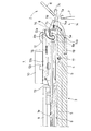
図1は、本発明の実施の一形態であるパイル編成方法に使用する横編機1の主要部分の構成を示す。横編機1は、歯口2で前後の針床が対向する。図では一方の針床3を示し、他方の針床は省略する。歯口2に対して針床3は、歯口2側が高く、歯口2から遠ざかる程低くなるように傾斜している。すなわち前後の針床3は、歯口2を中心として逆V字状に配置される。ただし、説明の便宜上、一方の針床3を水平な姿勢で示す。一方の針床3に関する構成は、他方の針床に関しても基本的に同様である。
FIG. 1 shows a configuration of main parts of a
針床3は、編地編成領域である歯口2に臨んで配置される基台4に、多数のニードルプレート5をそれぞれ歯口2に向う方向に植設している。ニードルプレート5は歯口2側の端部で板厚が薄くなって、ニードルプレート5間に歯口2側で幅が拡大するような針溝6を形成し、各針溝6に編針7を収容し、幅が拡大する端部には可動シンカー8をそれぞれ収容して針床3を形成している。編針7は、複合針であり、針本体7aとスライダ7bとを独立に移動させることができる。針本体7aの先端にはフック7cが形成され、スライダ7bの先端は、2枚の弾性板に分かれ、先端部分には段差を有するタング7dが形成されている。スライダ7bのタング7dは、針本体7aのフック7cを摺動自在に挟持している。このような複合針については、特許文献3の段落[0016]〜[0019]や図面の図2〜図4で、詳細に説明されている。また、特許文献4、5に開示されているような複合針を使用することも可能である。
The
横編機1では、針床3上を歯口2に沿って、すなわち紙面に垂直にキャリッジを往復走行させながら、歯口2に対して編針7を選択的に進退させて、可動シンカー8との相互作用で編地を編成する。ただし、キャリッジは図示を省略して、編針7を作動させる編針作動用カム機構9と、可動シンカー8を作動させるシンカー作動用カム機構10とを示す。編針作動用カム機構9では、針本体7aとスライダ7bとを、選択的に、かつ別個に作動させることができる。
In the
歯口2では、ヤーンフィーダ11から編針7に編糸を供給して、編目ループを形成させることができる。編針7は、各針溝6内で幅方向に関して可動シンカー8と並べて配置される。針本体7aには、歯口2への進退変位を駆動するバットが設けられるけれども、図の左方の位置となるので図示を省略する。スライダ7bには、歯口2への進退変位を駆動するバット7eが設けられる。ニードルプレート5は、歯口2側の端部に、可動シンカー8を揺動変位可能に支承する凹部5aを有する。可動シンカー8は、凹部5aに支承される基部8aと、歯口2に対する進退変位を受けて駆動される受動部8bとを有する。各針溝6内には、歯口2に対して直線的に進退変位可能なシンカージャック12が収納される。シンカージャック12は、端部12aで可動可動シンカー8の受動部8bと係合し、端部12aに対して歯口2から離れる方向に延びる基部12b側に、針床3の基台4から離れる方向に突出するバット12cを有し、シンカー作動用カム機構10による作用を受ける。
In the
各針溝6内には、スペーサ13が、編針7に対して針床3の基台4から離れる方向に配置され、底部で編針7が基台4から離れないように規制し、側部でシンカージャック12が針溝6の幅方向にずれないように規制する。可動シンカー8は、受動部8bに対する進退変位が基部8aを支点とする揺動変位に変換されて、歯口2に対してシンカーとして作用する先端部14を有する。先端部14には、編糸受け部14aが形成される。帯金15は、各針溝6内のスペーサ13およびニードルプレート5を歯口2に沿う方向、すなわち紙面に垂直な方向に貫通して相互に固定する。帯金15は、シンカージャック12にも挿通されて、シンカージャック12が針溝6から離れないで摺動変位するように規制する。
In each
可動シンカー8の基部8aには、可動シンカー8を図の時計回り方向に付勢する線ばね16が設けられる。ワイヤ17は、ニードルプレート5と基台4との固定のために使用されている。基台4の底部の歯口2寄りの位置には、可動シンカー8の先端部14の先端14bが当接して、線ばね16による付勢で可動シンカー8が揺動変位するのを規制するストッパ18が設けられている。
A
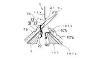
図2〜図11は、前後の針床3を使用して筒状のパイル編地を編成する際の編針7の作動状態を、歯口2付近の側面断面視で簡略化して示す。なお、説明の便宜上、横編機1の正面から見て前方側の針床3に対して、後方側に関連する構成部分は、前方側の対応する構成部分の参照番号に100を加えた参照番号で示す。また、編針7に編成動作を行わせるキャリッジに搭載される編針編成用カム機構9には、前後の針床3,103に対して、編成用のカムシステムが1システムずつ設けられるものとする。複数のシステムを設けることが可能であるのはもちろんであり、複数のシステムが設けられていれば、1回のキャリッジの移動で、複数コース分の動作を行わせることができ、キャリッジの移動回数を減少させることができる。また、締糸用のヤーンフィーダ11aとパイル糸用のヤーンフィーダ11bとは、針床3の長手方向の一方側で待機するものとする。
FIGS. 2-11 shows the operation state of the
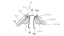
図2は、1コース目として、前方側の針床3で編成する編地20へのパイル編目形成を開始する状態を示す。後方側の針床103で編成する編地120は、編針107の針本体107aのフック107cに保持しておく。キャリッジには、締糸21を供給するヤーンフィーダ11aを連行させる。前方側の針床3では、スライダ7bのタング7dに締糸21とパイル糸22とによる旧ループ23を係止した状態で、針本体7aが歯口2に上昇進出し、フック7cに、ヤーンフィーダ11aから締糸21の供給を受ける。
FIG. 2 shows a state in which pile stitch formation on the knitted
図3は、図2に続けて、スライダ7bはそのままの状態で、針本体7aを歯口2から下降後退させ、締糸21を引込む状態を示す。引込みは最小限で行うように、たとえば編成作動用カム機構9の編成用のカムシステムに設けられる度山の度目を設定し、スライダ7bがフック7aよりも高い位置であっても、ノックオーバはさせないようにする。後方側の針床103では、スライダ107bを歯口2に上昇進出させておく。このタイミングでスライダ107bを上昇進出させるのは、キャリッジに搭載される編成カムの都合による。後方側のスライダ107bを歯口2に上昇進出させるのは、給糸位置の直前までに終了すればよく、必ずしも図3のタイミングに限定されるわけではない。
FIG. 3 shows a state in which the
前述のように、両ヤーンフィーダ11a,11bを針床3の同じ側に配置しているので、2コース目は、1コース目とは逆方向にキャリッジを移動させる必要がある。しかも、編針7、107には何も作用させない空コースとする必要がある。
As described above, since both yarn feeders 11a and 11b are arranged on the same side of the
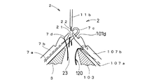
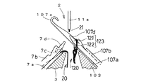
図4は、3コース目として、1コース目と同一の方向へキャリッジを移動させ、パイル糸22を供給するヤーンフィーダ11bを連行させて、フック7cでパイル糸22を受ける状態を示す。前方側の針床3では、スライダ7bのタング7dに旧ループ23を係止した状態で、針本体7aをタック位置まで上昇させる。針本体7aのフック7d内には、締糸21が保持されている。ヤーンフィーダ11bからパイル糸22をフック7cに供給すると、フック7c内には締糸21およびパイル糸22が保持される。パイル糸22は、既に上昇して歯口2内に進出している後方側の針床103のスライダ107bのタング107dにも掛けられる。
FIG. 4 shows a state where, as the third course, the carriage is moved in the same direction as the first course, the yarn feeder 11b for supplying the
図5は、図4に続けて、前方側の針床3で針本体7aおよびスライダ7bをともに下降させて引込み、スライダ7bのタング7dに係止していた旧ループ23をノックオーバさせた状態を示す。後方側の針床103のスライダ107bのタング107dに掛けられたパイル糸22は、引出されてパイル編目24を形成する。編地20は、フック7cによって保持される。
FIG. 5 shows a state in which the
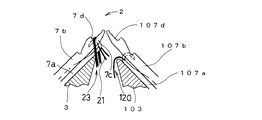
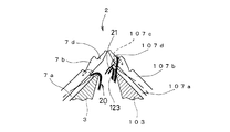
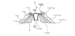
図6は、4コース目の始めの方で、後方側の針床103のスライダ107bを歯口2から下降後退させて、タング107dに掛けられていたパイル編目24を払う状態を示す。パイル編目24は、前方側の針床3に保持されている編地20の表面から突出するパイルループ25となる。このパイルループ25は、キャリッジにステッチプレッサなどのループ押えを備えておき、ループ押えで歯口2内に押えるようにすることが好ましい。なお、ステッチプレッサの詳細な説明は、たとえば特公平3−66415号公報に開示されている。また、キャリッジには、締糸21を供給するヤーンフィーダ11aを連行させる。
FIG. 6 shows a state in which the
図7は、図6に続いて、後方側の針床103で編成する編地120へのパイル編目形成を開始する状態を示す。前方側の針床3で編成する編地20は、編針7の針本体7aのフック7cに保持しておく。後方側の針床103では、スライダ107bのタング107dに締糸21とパイル糸22とによる旧ループ123を係止した状態で、針本体107aが歯口2に上昇進出し、フック107cに、ヤーンフィーダ11aから締糸21の供給を受ける。
FIG. 7 shows a state in which the formation of pile stitches on the
図8は、図7に続けて、スライダ107bはそのままの状態で、針本体107aを歯口2から下降後退させ、締糸21を引込む状態を示す。引込みは最小限で行うように、たとえば編成作動用カム機構9の編成用のカムシステムに設けられる度山の度目を設定し、スライダ107bがフック107aよりも高い位置であっても、ノックオーバはさせないようにする。図3について説明しているような理由で、前方側の針床3では、スライダ7bを歯口2に上昇進出させておく。
5コース目は、4コース目とは逆方向にキャリッジを移動させる空コースとする。
FIG. 8 shows a state in which the
The fifth course is an empty course in which the carriage is moved in the opposite direction to the fourth course.
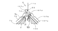
図9は、6コース目として、4コース目と同一の方向へキャリッジを移動させ、パイル糸22を供給するヤーンフィーダ11bを連行させて、フック107cでパイル糸22を受ける状態を示す。後方側の針床103では、スライダ107bのタング107dに旧ループ123を係止した状態で、針本体107aをタック位置まで上昇させる。針本体107aのフック107d内には、締糸21が保持されている。ヤーンフィーダ11bからパイル糸22をフック107cに供給すると、フック107c内には締糸21およびパイル糸22が保持される。パイル糸22は、既に上昇して歯口2内に進出している前方側の針床3のスライダ7bのタング7dにも掛けられる。
FIG. 9 shows a state where, as the sixth course, the carriage is moved in the same direction as the fourth course, the yarn feeder 11b for supplying the
図10は、図9に続けて、後方側の針床103で針本体107aおよびスライダ107bをともに下降させて引込み、スライダ107bのタング107dに係止していた旧ループ123をノックオーバさせた状態を示す。前方側の針床3のスライダ7bのタング7dに掛けられたパイル糸22は、引出されてパイル編目124を形成する。編地120は、フック107cによって保持される。
FIG. 10 shows a state in which the needle
図11は、7コース目の始めの方で、前方側の針床3のスライダ7bを歯口2から下降後退させて、タング7dに掛けられていたパイル編目124を払う状態を示す。パイル編目124は、後方側の針床103に保持されている編地120の表面から突出するパイルループ125となる。図6と同様に、パイルループ125を歯口2に押込むためには、ループ押えを好適に用いることができる。7コース目の続きは、図2と同様になり、新たな1コース目と考えることができる。このように、1コース目から6コース目のパイルループ25,125の形成を繰返すことによって、編地20,120が両端で連結する筒状のパイル編地を編成することができる。前述のように、キャリッジに搭載する編成カムに複数のシステムを設けるようにすれば、キャリッジの移動の回数を減少させることができる。
FIG. 11 shows a state in which the
以上で説明しているように、たとえば編針7が備えられる前方側の針床3で編成する編地20にパイル編目24を形成する際には、その編針7に締糸21とパイル糸22とによる旧ループ23を係止している状態で、フック7cを歯口2に進出させて、そのフック7cに新ループの締糸21を供給する。締糸21が供給されたフック7cを歯口2から後退させて、係止している旧ループ23をノックオーバさせない範囲で締糸21を引込む。締糸21のみをフック7cに保持する状態でフック7cを歯口2に進出させて、パイル糸22をフック7cと針床3に対向する後方側の針床103の複合針である編針107のスライダ107bのタング107dとに供給する。フック7c内にはすでに締糸21が供給されているので、パイル糸22の供給によって、編針7のフック7cには締糸21とともにパイル糸22も保持されるようになる。編針7のフック7cを歯口2から後退させて、フック7cで新ループの締糸21とパイル糸22とを編針7に係止されている旧ループ23内に引込んで、旧ループ23をノックオーバさせる。パイル糸22は、対向する針床103側のスライダ107bのタング107dにも掛っているので、パイル編目24として引出される。複合針のスライダ107bを歯口2から後退させて、スライダ107bのタング107dに掛けられているパイル糸22を解放してパイルループ25を形成するので、複合針の針本体107aはパイルループ25の形成には使用する必要がなく、他の編目を保持することができる。
As described above, for example, when the pile stitches 24 are formed on the knitted
また、前後の針床3,103に編針7,107として複合針が備えられていれば、歯口2で、前後の針床3,103の複合針に締糸21およびパイル糸22をそれぞれ供給して、編地20,120の両端で連結する筒状の編地や、一端で連結する編地を編成することができる。前後の針床で別個の編地を同時に編成することもできる。一方の針床側で編成する編地20の少なくとも一部にパイル編目24を形成する際には、他方の針床の複合針のフック107cに他方の針床103側で編成する編地120を保持する状態で、そのフック107cを歯口2から後退させておく。他方の複合針のスライダ107bを歯口2に進出させて、そのスライダ107bのタング107dと、一方の針床3の複合針とを使用してパイル編目24を形成する。他方の針床103側で編成する編地120の少なくとも一部にパイル編目124を形成する際には、一方の針床3の複合針のフック7cに一方の針床3側で編成する編地20を保持する状態で、そのフック7cを歯口2から後退させておく。一方の複合針のスライダ7bを歯口2に進出させて、そのスライダ7bのタング7dと、他方の針床103の複合針とを使用してパイル編目124を形成する。したがって、筒状の編地にパイル編目24,124やパイルループ25,125を形成することができる。
Further, if the front and
なお、複合針を使用するのは、前後の針床3,103の一方のみでもよい。その場合、複合針を使用する針床に対向する針床側で編成する編地に、パイル編目を形成することができる。すなわち、歯口2を挟んで対向する前後の針床3,103の少なくとも一方に複合針を備える横編機1で、歯口2に締糸21とパイル糸22とを供給してパイル編地を編成することができる。歯口2に締糸21とパイル糸22とを供給して、複合針のスライダ7b,107bのタング7d,107dにはパイル糸22のみを掛け、その複合針が備えられる針床3,103に対向する針床に備えられる編針には締糸21とパイル糸22とを供給して編目を形成する。パイル糸22が掛けられた複合針のスライダ7b,107bを歯口2から後退させると、パイル糸22はスライダ7b,107bのタング7d,107dから脱落して解放される。パイル糸22が複合針から解放されるので、べら針など、複合針ではない編針が備えられる針床側で編成する編地にパイルループ編目を形成することができる。複合針の針本体7a,107aはパイル編目の形成に使用しないので、パイル編目の形成の際に、他の編目を保持することも可能である。
The compound needle may be used for only one of the front and back needle beds 3,103. In that case, pile stitches can be formed on the knitted fabric knitted on the needle bed side facing the needle bed using the compound needle. That is, in a
1 横編機
2 歯口
3,103 針床
7、107 編針
7a,107a 針本体
7b,107b スライダ
7c,107c フック
7d,107d タング
9 編針作動用カム機構
11,11a,11b ヤーンフィーダ
20,120 編地
21 締糸
22 パイル糸
23,123 旧ループ
24,124 パイル編目
25,125 パイルループ
DESCRIPTION OF
Claims (4)
該編針にパイル糸を供給する際には、同時に該複合針のスライダのタングにもパイル糸を掛け、
該編針に締糸を供給する際には、該複合針には該締糸は供給しないで、
パイル編目のみが該複合針のスライダのタングに保持されるようにパイル糸および締糸による編目を形成し、
該複合針のスライダを歯口から後退させて、パイル編目を該スライダのタングから解放し、
該編針で編成する編地にパイルループを形成することを特徴とする横編機によるパイル編成方法。 A flat knitting machine comprising a slider and a needle body on at least one of the front and back needle beds facing each other with a tooth opening, the slider being provided with a compound needle that can advance into the tooth opening rather than a hook of the needle body; A method of knitting a pile knitted fabric by supplying a knitting needle and a pile yarn to a knitting needle on a needle bed side facing the needle bed provided at the mouth,
When supplying pile yarn to the knitting needle, simultaneously pile pile yarn on the tongue of the composite needle,
When supplying the thread to the knitting needle, do not supply the thread to the compound needle.
Forming pile stitches and pile stitches so that only the pile stitches are held by the tongue of the composite needle slider;
Retreating the slider of the compound needle from the tooth opening to release the pile stitch from the tongue of the slider;
A pile knitting method using a flat knitting machine, wherein a pile loop is formed on a knitted fabric knitted with the knitting needle.
一方の針床側で編成する編地の少なくとも一部にパイル編目を形成する際には、他方の針床の複合針のフックに該他方の針床側で編成する編地を保持する状態で、該フックを前記歯口から後退させておき、該他方の複合針のスライダを該歯口に進出させて、該スライダのタングと、該一方の針床の複合針とを使用して該パイル編目を形成し、
該他方の針床側で編成する編地の少なくとも一部にパイル編目を形成する際には、該一方の針床の複合針のフックに該一方の針床側で編成する編地を保持する状態で、該フックを前記歯口から後退させておき、該一方の複合針のスライダを該歯口に進出させて、該スライダのタングと、該他方の針床の複合針を使用して該パイル編目を形成することを特徴とする請求項1記載の横編機によるパイル編地の編成方法。 The front and back needle beds are each provided with the compound needle as the knitting needle,
When forming pile stitches on at least a part of the knitted fabric knitted on one needle bed side, the knitted fabric knitted on the other needle bed side is held on the hook of the composite needle of the other needle bed. The hook is retracted from the tooth opening, the slider of the other composite needle is advanced into the tooth opening, and the pile of the pile is formed using the tongue of the slider and the composite needle of the one needle bed. Forming stitches,
When forming pile stitches on at least a part of the knitted fabric knitted on the other needle bed side, the knitted fabric knitted on the one needle bed side is held by the hook of the composite needle of the one needle bed side. In this state, the hook is retracted from the tooth opening, the slider of the one composite needle is advanced to the tooth opening, and the tongue of the slider and the composite needle of the other needle bed are used to 2. A pile knitting method using a flat knitting machine according to claim 1, wherein a pile stitch is formed.
該編針に締糸とパイル糸とによる旧ループを係止している状態で、該編針のフックを前記歯口に進出させて該フックに新ループの締糸を供給し、
該フックを該歯口から後退させて、該編針が係止している旧ループをノックオーバさせない範囲で該締糸を引込み、
該締糸のみを該フックに保持する状態で該フックを該歯口に進出させて、パイル糸を該フックと該針床に対向する針床側の複合針のスライダのタングとに供給し、
該編針のフックを該歯口から後退させて、該フックで新ループの締糸とパイル糸とを該編針に係止されている旧ループ内に引込んで、該旧ループをノックオーバさせ、
該複合針のスライダを該歯口から後退させて、該スライダのタングに掛けられているパイル編目を解放してパイルループを形成することを特徴とする請求項1または2記載の横編機によるパイル編成方法。 When forming the pile stitches on the knitted fabric knitted on the needle bed side provided with the knitting needles,
In a state in which the old loop of the knitting needle and the pile yarn is locked to the knitting needle, the hook of the knitting needle is advanced into the tooth opening and the new loop is supplied to the hook.
Retract the hook from the mouth and pull the thread in a range that does not knock over the old loop locked by the knitting needle,
With the hook held only on the hook, the hook is advanced into the tooth opening, and the pile thread is supplied to the hook and the tongue of the composite needle slider on the needle bed side facing the needle bed,
Retracting the hook of the knitting needle from the mouth, and pulling the thread and pile yarn of the new loop into the old loop locked to the knitting needle with the hook, knocking over the old loop,
3. The flat knitting machine according to claim 1, wherein a pile loop is formed by retreating the slider of the compound needle from the tooth opening and releasing a pile stitch hung on the tongue of the slider. Pile knitting method.
The pile knitting method by a flat knitting machine according to any one of claims 1 to 3, wherein a pile loop formed by releasing the pile knitting stitch from the tongue of the slider is pressed into a tooth opening by a loop presser. .
Priority Applications (6)
| Application Number | Priority Date | Filing Date | Title |
|---|---|---|---|
| JP2004103184A JP4180541B2 (en) | 2004-03-31 | 2004-03-31 | Pile knitting method with flat knitting machine |
| EP05727615A EP1731647B1 (en) | 2004-03-31 | 2005-03-29 | Pile knitting method by weft knitting machine |
| KR1020067021117A KR101061821B1 (en) | 2004-03-31 | 2005-03-29 | Pile knitting method by flat knitting machine |
| US10/594,890 US7272957B2 (en) | 2004-03-31 | 2005-03-29 | Pile knitting method by weft knitting machine |
| CNB2005800104599A CN100503922C (en) | 2004-03-31 | 2005-03-29 | Plush knitting method of flat knitting machine |
| PCT/JP2005/005961 WO2005095697A1 (en) | 2004-03-31 | 2005-03-29 | Pile knitting method by weft knitting machine |
Applications Claiming Priority (1)
| Application Number | Priority Date | Filing Date | Title |
|---|---|---|---|
| JP2004103184A JP4180541B2 (en) | 2004-03-31 | 2004-03-31 | Pile knitting method with flat knitting machine |
Publications (2)
| Publication Number | Publication Date |
|---|---|
| JP2005290572A true JP2005290572A (en) | 2005-10-20 |
| JP4180541B2 JP4180541B2 (en) | 2008-11-12 |
Family
ID=35063815
Family Applications (1)
| Application Number | Title | Priority Date | Filing Date |
|---|---|---|---|
| JP2004103184A Expired - Fee Related JP4180541B2 (en) | 2004-03-31 | 2004-03-31 | Pile knitting method with flat knitting machine |
Country Status (6)
| Country | Link |
|---|---|
| US (1) | US7272957B2 (en) |
| EP (1) | EP1731647B1 (en) |
| JP (1) | JP4180541B2 (en) |
| KR (1) | KR101061821B1 (en) |
| CN (1) | CN100503922C (en) |
| WO (1) | WO2005095697A1 (en) |
Cited By (6)
| Publication number | Priority date | Publication date | Assignee | Title |
|---|---|---|---|---|
| WO2007058275A1 (en) * | 2005-11-17 | 2007-05-24 | Shima Seiki Manufacturing Limited | Weft knitting machine capable of inserting warp and knitting method by that weft knitting machine |
| WO2007058273A1 (en) * | 2005-11-17 | 2007-05-24 | Shima Seiki Manufacturing Limited | Method and device for cutting/holding warp of weft knitting machine |
| JP2014047446A (en) * | 2012-08-31 | 2014-03-17 | Shima Seiki Mfg Ltd | Pile knitting method and knitting fabric having pile knitting part |
| JP2017053042A (en) * | 2015-09-07 | 2017-03-16 | 株式会社Modellista | Pile knitting method by flat knitting machine |
| JP7438011B2 (en) | 2020-04-30 | 2024-02-26 | 株式会社島精機製作所 | How to knit pile fabric using flat knitting machine |
| JP7674187B2 (en) | 2021-08-05 | 2025-05-09 | 株式会社島精機製作所 | Method for knitting pile fabric using a flat knitting machine |
Families Citing this family (6)
| Publication number | Priority date | Publication date | Assignee | Title |
|---|---|---|---|---|
| JP5757830B2 (en) | 2011-09-13 | 2015-08-05 | 株式会社島精機製作所 | Flat knitting machine provided with compound needle, and slider control method of flat knitting machine |
| US20150315728A1 (en) * | 2015-07-13 | 2015-11-05 | Sung-Yun Yang | Process of manufacturing fabrics having jacquard and terry patterns |
| JP7271398B2 (en) * | 2019-11-15 | 2023-05-11 | 株式会社島精機製作所 | Flat knitting machine for pile knitting and knitting method |
| JP2022138703A (en) * | 2021-03-10 | 2022-09-26 | 株式会社島精機製作所 | Method of knitting pile knitted fabric by flat-knitting machine |
| JP7655678B2 (en) * | 2021-07-21 | 2025-04-02 | 株式会社島精機製作所 | Method for knitting pile fabric using a flat knitting machine |
| JP7624909B2 (en) * | 2021-10-25 | 2025-01-31 | 株式会社島精機製作所 | Flat knitting machine and sinker for pile knitting, and pile knitting method with flat knitting machine |
Family Cites Families (7)
| Publication number | Priority date | Publication date | Assignee | Title |
|---|---|---|---|---|
| US5937673A (en) * | 1997-05-01 | 1999-08-17 | Shima Seiki Manufacturing, Ltd. | Compound needle of a flat knitting machine |
| CH691543A5 (en) * | 1997-05-27 | 2001-08-15 | Steiger Sa Atelier Constr | Compound needle for knitting machine. |
| US6047569A (en) * | 1997-05-27 | 2000-04-11 | Shima Seiki Manufacturing, Ltd. | Method for holding a stitch loop |
| DE69809141T2 (en) * | 1997-07-11 | 2003-07-24 | Shima Seiki Mfg. Ltd., Wakayama | Mesh forming method and flat knitting machine therefor |
| JP2917146B2 (en) | 1997-07-11 | 1999-07-12 | 株式会社島精機製作所 | Stitch forming method and flat knitting machine for forming the stitch |
| IT1307796B1 (en) * | 1999-09-14 | 2001-11-19 | Pinzauti Lucia | DEVICE AND PROCEDURE FOR THE CONSTRUCTION OF KNITTED FABRICS WITH THE FORMATION OF HAIR CUT ON A REVERSE KNIT, WHOSE RANGES OF |
| FR2821093B1 (en) * | 2001-02-20 | 2003-05-09 | Steiger S A C Atel Const | SLIDING NEEDLE FOR KNITTING MACHINE |
-
2004
- 2004-03-31 JP JP2004103184A patent/JP4180541B2/en not_active Expired - Fee Related
-
2005
- 2005-03-29 WO PCT/JP2005/005961 patent/WO2005095697A1/en not_active Ceased
- 2005-03-29 US US10/594,890 patent/US7272957B2/en not_active Expired - Fee Related
- 2005-03-29 EP EP05727615A patent/EP1731647B1/en not_active Expired - Lifetime
- 2005-03-29 CN CNB2005800104599A patent/CN100503922C/en not_active Expired - Fee Related
- 2005-03-29 KR KR1020067021117A patent/KR101061821B1/en not_active Expired - Fee Related
Cited By (8)
| Publication number | Priority date | Publication date | Assignee | Title |
|---|---|---|---|---|
| WO2007058275A1 (en) * | 2005-11-17 | 2007-05-24 | Shima Seiki Manufacturing Limited | Weft knitting machine capable of inserting warp and knitting method by that weft knitting machine |
| WO2007058273A1 (en) * | 2005-11-17 | 2007-05-24 | Shima Seiki Manufacturing Limited | Method and device for cutting/holding warp of weft knitting machine |
| JP5057992B2 (en) * | 2005-11-17 | 2012-10-24 | 株式会社島精機製作所 | Flat knitting machine capable of inserting warp and knitting method using the flat knitting machine |
| JP5160897B2 (en) * | 2005-11-17 | 2013-03-13 | 株式会社島精機製作所 | Method and apparatus for cutting and holding warp of flat knitting machine |
| JP2014047446A (en) * | 2012-08-31 | 2014-03-17 | Shima Seiki Mfg Ltd | Pile knitting method and knitting fabric having pile knitting part |
| JP2017053042A (en) * | 2015-09-07 | 2017-03-16 | 株式会社Modellista | Pile knitting method by flat knitting machine |
| JP7438011B2 (en) | 2020-04-30 | 2024-02-26 | 株式会社島精機製作所 | How to knit pile fabric using flat knitting machine |
| JP7674187B2 (en) | 2021-08-05 | 2025-05-09 | 株式会社島精機製作所 | Method for knitting pile fabric using a flat knitting machine |
Also Published As
| Publication number | Publication date |
|---|---|
| EP1731647A4 (en) | 2007-05-02 |
| JP4180541B2 (en) | 2008-11-12 |
| CN1938466A (en) | 2007-03-28 |
| WO2005095697A1 (en) | 2005-10-13 |
| CN100503922C (en) | 2009-06-24 |
| EP1731647B1 (en) | 2011-05-11 |
| KR20070022681A (en) | 2007-02-27 |
| US20070180865A1 (en) | 2007-08-09 |
| EP1731647A1 (en) | 2006-12-13 |
| US7272957B2 (en) | 2007-09-25 |
| KR101061821B1 (en) | 2011-09-05 |
Similar Documents
| Publication | Publication Date | Title |
|---|---|---|
| KR100554199B1 (en) | Method of knitting inlaid fabric and inlaid fabric knitted by the method | |
| JP4180541B2 (en) | Pile knitting method with flat knitting machine | |
| JPWO2001036730A1 (en) | Sinker device for flat knitting machines | |
| JPH1181101A (en) | Formation of knitted stitch and flat knitting machine for forming the knitted stitch | |
| KR20210059630A (en) | Flatbed knitting machine for knitting pile fabric and knitting method thereof | |
| JP2011094266A (en) | Movable sinker and weft knitting machine | |
| JP2015132026A (en) | Flat knitting machine including sinker device | |
| JP5010588B2 (en) | Knitting method and flat knitting machine for intarsia pattern knitted fabric | |
| JP4348286B2 (en) | Flat knitting machine | |
| JP4176038B2 (en) | Movable sinker device of flat knitting machine | |
| JP2019210559A (en) | Method for knitting pile fabric, sinker, and flat-knitting machine | |
| JP3158109B2 (en) | Stitch locking method by flat knitting machine | |
| JP2013139644A (en) | Sinker device of flat knitting machine | |
| JP5719544B2 (en) | Compound needle of flat knitting machine | |
| JP2011017090A (en) | Device and method for knitting spacer fabric | |
| JP2004316063A (en) | Flat knitting machine having at least two needle beds | |
| CN117098884A (en) | Movable sinker for flat knitting machine | |
| CN221320261U (en) | Flat knitting machine with movable sinker | |
| JPS6252064B2 (en) | ||
| JP2020016008A (en) | Flat-knitting machine | |
| JP4175977B2 (en) | Flat knitting machine with movable sinker | |
| JP2000314057A (en) | How to organize | |
| WO2022191204A1 (en) | Method for knitting punch-lace knitted fabric produced by flat-knitting machine | |
| JPH093753A (en) | Yarn feeder in weft knitting machine | |
| JPWO2009016802A1 (en) | Knitting method of knitted fabric and flat knitting machine |
Legal Events
| Date | Code | Title | Description |
|---|---|---|---|
| A621 | Written request for application examination |
Free format text: JAPANESE INTERMEDIATE CODE: A621 Effective date: 20070223 |
|
| TRDD | Decision of grant or rejection written | ||
| A01 | Written decision to grant a patent or to grant a registration (utility model) |
Free format text: JAPANESE INTERMEDIATE CODE: A01 Effective date: 20080805 |
|
| A01 | Written decision to grant a patent or to grant a registration (utility model) |
Free format text: JAPANESE INTERMEDIATE CODE: A01 |
|
| A61 | First payment of annual fees (during grant procedure) |
Free format text: JAPANESE INTERMEDIATE CODE: A61 Effective date: 20080827 |
|
| R150 | Certificate of patent or registration of utility model |
Free format text: JAPANESE INTERMEDIATE CODE: R150 |
|
| FPAY | Renewal fee payment (event date is renewal date of database) |
Free format text: PAYMENT UNTIL: 20110905 Year of fee payment: 3 |
|
| FPAY | Renewal fee payment (event date is renewal date of database) |
Free format text: PAYMENT UNTIL: 20120905 Year of fee payment: 4 |
|
| FPAY | Renewal fee payment (event date is renewal date of database) |
Free format text: PAYMENT UNTIL: 20130905 Year of fee payment: 5 |
|
| LAPS | Cancellation because of no payment of annual fees |