JP2005290178A - Treating system of waste material, such as tire, and treating method of the same - Google Patents
Treating system of waste material, such as tire, and treating method of the same Download PDFInfo
- Publication number
- JP2005290178A JP2005290178A JP2004106576A JP2004106576A JP2005290178A JP 2005290178 A JP2005290178 A JP 2005290178A JP 2004106576 A JP2004106576 A JP 2004106576A JP 2004106576 A JP2004106576 A JP 2004106576A JP 2005290178 A JP2005290178 A JP 2005290178A
- Authority
- JP
- Japan
- Prior art keywords
- gas
- processing
- dry distillation
- waste
- furnace
- Prior art date
- Legal status (The legal status is an assumption and is not a legal conclusion. Google has not performed a legal analysis and makes no representation as to the accuracy of the status listed.)
- Pending
Links
- 239000002699 waste material Substances 0.000 title claims abstract description 71
- 238000000034 method Methods 0.000 title claims description 28
- 238000000197 pyrolysis Methods 0.000 claims abstract description 146
- 239000012535 impurity Substances 0.000 claims abstract description 51
- 239000000428 dust Substances 0.000 claims abstract description 10
- 239000000126 substance Substances 0.000 claims abstract description 3
- 238000001816 cooling Methods 0.000 claims description 37
- 238000004380 ashing Methods 0.000 claims description 35
- 238000003763 carbonization Methods 0.000 claims description 29
- 238000010438 heat treatment Methods 0.000 claims description 25
- 238000003672 processing method Methods 0.000 claims description 14
- NINIDFKCEFEMDL-UHFFFAOYSA-N Sulfur Chemical compound [S] NINIDFKCEFEMDL-UHFFFAOYSA-N 0.000 claims description 9
- 229910052717 sulfur Inorganic materials 0.000 claims description 9
- 239000011593 sulfur Substances 0.000 claims description 9
- 238000011144 upstream manufacturing Methods 0.000 claims description 8
- 238000002485 combustion reaction Methods 0.000 claims description 3
- 239000000463 material Substances 0.000 claims 1
- 239000010920 waste tyre Substances 0.000 abstract description 38
- 150000003464 sulfur compounds Chemical class 0.000 abstract description 8
- 231100000614 poison Toxicity 0.000 abstract description 2
- 230000007096 poisonous effect Effects 0.000 abstract 1
- 239000000843 powder Substances 0.000 abstract 1
- 239000007789 gas Substances 0.000 description 206
- 239000007788 liquid Substances 0.000 description 25
- 238000011049 filling Methods 0.000 description 18
- 238000002156 mixing Methods 0.000 description 13
- XEEYBQQBJWHFJM-UHFFFAOYSA-N Iron Chemical compound [Fe] XEEYBQQBJWHFJM-UHFFFAOYSA-N 0.000 description 10
- 229910052742 iron Inorganic materials 0.000 description 5
- 238000010304 firing Methods 0.000 description 4
- IJGRMHOSHXDMSA-UHFFFAOYSA-N Atomic nitrogen Chemical compound N#N IJGRMHOSHXDMSA-UHFFFAOYSA-N 0.000 description 3
- 229910001873 dinitrogen Inorganic materials 0.000 description 3
- 239000002184 metal Substances 0.000 description 3
- 229910052751 metal Inorganic materials 0.000 description 3
- CURLTUGMZLYLDI-UHFFFAOYSA-N Carbon dioxide Chemical compound O=C=O CURLTUGMZLYLDI-UHFFFAOYSA-N 0.000 description 2
- 230000003247 decreasing effect Effects 0.000 description 2
- 238000001514 detection method Methods 0.000 description 2
- 150000002013 dioxins Chemical class 0.000 description 2
- 238000004880 explosion Methods 0.000 description 2
- 230000009931 harmful effect Effects 0.000 description 2
- VNWKTOKETHGBQD-UHFFFAOYSA-N methane Chemical compound C VNWKTOKETHGBQD-UHFFFAOYSA-N 0.000 description 2
- 239000012466 permeate Substances 0.000 description 2
- XLYOFNOQVPJJNP-UHFFFAOYSA-N water Substances O XLYOFNOQVPJJNP-UHFFFAOYSA-N 0.000 description 2
- KVGZZAHHUNAVKZ-UHFFFAOYSA-N 1,4-Dioxin Chemical compound O1C=COC=C1 KVGZZAHHUNAVKZ-UHFFFAOYSA-N 0.000 description 1
- QAOWNCQODCNURD-UHFFFAOYSA-N Sulfuric acid Chemical class OS(O)(=O)=O QAOWNCQODCNURD-UHFFFAOYSA-N 0.000 description 1
- 239000011449 brick Substances 0.000 description 1
- 229910002092 carbon dioxide Inorganic materials 0.000 description 1
- 239000001569 carbon dioxide Substances 0.000 description 1
- 238000010000 carbonizing Methods 0.000 description 1
- 238000006243 chemical reaction Methods 0.000 description 1
- 230000005484 gravity Effects 0.000 description 1
- 238000010030 laminating Methods 0.000 description 1
- 239000003345 natural gas Substances 0.000 description 1
- 230000000149 penetrating effect Effects 0.000 description 1
- 239000011291 pitch of tar Substances 0.000 description 1
- 239000000047 product Substances 0.000 description 1
- 230000002787 reinforcement Effects 0.000 description 1
- 230000003014 reinforcing effect Effects 0.000 description 1
- 239000003440 toxic substance Substances 0.000 description 1
- 238000003466 welding Methods 0.000 description 1
Images
Classifications
-
- Y—GENERAL TAGGING OF NEW TECHNOLOGICAL DEVELOPMENTS; GENERAL TAGGING OF CROSS-SECTIONAL TECHNOLOGIES SPANNING OVER SEVERAL SECTIONS OF THE IPC; TECHNICAL SUBJECTS COVERED BY FORMER USPC CROSS-REFERENCE ART COLLECTIONS [XRACs] AND DIGESTS
- Y02—TECHNOLOGIES OR APPLICATIONS FOR MITIGATION OR ADAPTATION AGAINST CLIMATE CHANGE
- Y02P—CLIMATE CHANGE MITIGATION TECHNOLOGIES IN THE PRODUCTION OR PROCESSING OF GOODS
- Y02P20/00—Technologies relating to chemical industry
- Y02P20/141—Feedstock
- Y02P20/143—Feedstock the feedstock being recycled material, e.g. plastics
-
- Y—GENERAL TAGGING OF NEW TECHNOLOGICAL DEVELOPMENTS; GENERAL TAGGING OF CROSS-SECTIONAL TECHNOLOGIES SPANNING OVER SEVERAL SECTIONS OF THE IPC; TECHNICAL SUBJECTS COVERED BY FORMER USPC CROSS-REFERENCE ART COLLECTIONS [XRACs] AND DIGESTS
- Y02—TECHNOLOGIES OR APPLICATIONS FOR MITIGATION OR ADAPTATION AGAINST CLIMATE CHANGE
- Y02W—CLIMATE CHANGE MITIGATION TECHNOLOGIES RELATED TO WASTEWATER TREATMENT OR WASTE MANAGEMENT
- Y02W30/00—Technologies for solid waste management
- Y02W30/50—Reuse, recycling or recovery technologies
- Y02W30/62—Plastics recycling; Rubber recycling
Landscapes
- Separation, Recovery Or Treatment Of Waste Materials Containing Plastics (AREA)
- Coke Industry (AREA)
Abstract
Description
本願発明は、廃棄物の処理システム、および、その処理方法に関し、より詳しくは廃タイヤの処理に適した発明である。 The present invention relates to a waste treatment system and a treatment method thereof, and more particularly, is an invention suitable for treatment of waste tires.
廃タイヤから乾留ガスを採取するにあっては、一般的には、廃タイヤをチップ化して、そのチップ状の廃タイヤを乾留炉内において乾留して乾留ガスを得て、乾留後の廃タイヤを別の処理手段によって灰にまですることがなされている。 In collecting dry distillation gas from waste tires, in general, waste tires are made into chips, the chip-like waste tires are dry-distilled in a dry distillation furnace to obtain dry distillation gas, and waste tires after dry distillation The ash is made into ash by another processing means.
かかる処理方法にあっては、タイヤをチップ化する必要があるとともに、乾留ガスを得た後の廃タイヤを乾留炉とは別の処理手段によって処理する必要があり、その作業が極めて煩雑であった。 In such a processing method, it is necessary to chip the tire, and it is necessary to process the waste tire after obtaining the carbonization gas by a processing means different from the carbonization furnace, which is very complicated. It was.
また、乾留後から、廃タイヤを炉内から除去するまでの間、乾留ガスを発生させることができず、乾留ガスを連続的に利用することができないという問題を有していた。 In addition, there has been a problem in that the carbonization gas cannot be generated and the carbonization gas cannot be continuously used until the waste tire is removed from the furnace after the carbonization.
また、廃タイヤの乾留処理に関して、一対の乾留炉およびボイラーを設けたものも公知である(特許文献1)。しかるに、廃タイヤの処理に際しては、有害な排ガスが発生するが、上記特許文献1においては、かかる考慮が一切なされていない。
そこで、本願発明は、上記問題に鑑み、廃タイヤ等を連続的に処理することができるとともに、発生する有毒な物質を排ガスから的確に除去することができるタイヤ等の廃棄物の処理システムを提供することを課題とする。 Therefore, in view of the above problems, the present invention provides a waste treatment system for tires and the like capable of continuously treating waste tires and the like and capable of accurately removing generated toxic substances from exhaust gas. The task is to do.
本願発明は上記課題を解決すべくなされたものであって、本願請求項1記載の発明に係るタイヤ等の廃棄物の処理システムとしての特徴は、タイヤ等の廃棄物から乾留ガスを発生させるべく廃棄物を密封状態で収容する複数の処理炉と、この複数の処理炉に接続され乾留ガスを下流側に供給する供給路とを備え、該供給路には、通過する気体中に含まれる粉塵、硫黄化物等の不純物を除去する不純物除去手段が設けられている点にある。 The present invention has been made to solve the above-mentioned problems, and the feature of the waste treatment system for tires and the like according to claim 1 of the present invention is to generate dry distillation gas from the wastes such as tires. A plurality of processing furnaces that contain waste in a sealed state; and a supply path that is connected to the plurality of processing furnaces and supplies dry distillation gas to the downstream side. The supply path includes dust contained in the passing gas. Further, an impurity removing means for removing impurities such as sulfurized substances is provided.
上記構成からなる本願発明に係る処理システムにあっては、一の処理炉によって乾留ガスを発生させて、その乾留ガスを供給路を介して下流側に供給することができる。特に、前記供給路には不純物除去手段が設けられているので、下流側において、乾留ガスのガス成分以外の排ガスを外部に放出したとしても、大気を汚染することを防止できる。また、供給路には複数の処理炉が接続されているため、たとえば、前記一の処理炉における乾留ガスの発生の後に、他の処理炉において乾留を開始して、乾留ガスを連続的に下流側に供給することが可能となる。また、上記のような乾留ガスの発生後に、一の処理炉において灰化にまで至らしめることができ、すなわち、一つの炉内において廃棄物の乾留から灰化までを一連で行うことができ、従前のように乾留後の廃棄物を他の処理手段に移送する必要がない。 In the processing system according to the present invention configured as described above, dry distillation gas can be generated by one processing furnace, and the dry distillation gas can be supplied to the downstream side through the supply path. In particular, since the supply path is provided with impurity removing means, it is possible to prevent the atmosphere from being polluted even if exhaust gas other than the gas component of the dry distillation gas is discharged to the outside on the downstream side. In addition, since a plurality of processing furnaces are connected to the supply path, for example, after generation of dry distillation gas in the one processing furnace, dry distillation is started in another processing furnace, and the dry distillation gas is continuously downstream. It becomes possible to supply to the side. In addition, after generation of the dry distillation gas as described above, it can be brought to ashing in one processing furnace, that is, a series of processes from dry distillation of waste to ashing can be performed in one furnace, As before, there is no need to transfer the waste after carbonization to other treatment means.
また、本願請求項2記載の発明に係るタイヤ等の廃棄物の処理システムとしての特徴は、タイヤ等の廃棄物から乾留ガスを発生させるべく廃棄物を密封状態で収容する複数の処理炉と、この複数の処理炉にそれぞれ接続され乾留ガスを下流側に供給する複数の供給路とを備え、各供給路には供給路内の気体を一定温度以上に加熱する加熱手段が設けられており、一の供給路の加熱手段は、他の供給路の乾留ガスの燃焼により加熱するように設けられている点にある。 Further, the feature of the waste treatment system for tires and the like according to the invention of claim 2 is that a plurality of treatment furnaces that contain waste in a sealed state so as to generate dry distillation gas from the wastes such as tires, A plurality of supply passages connected to the plurality of processing furnaces to supply the dry distillation gas to the downstream side, each supply passage is provided with a heating means for heating the gas in the supply passage to a certain temperature or higher, The heating means of one supply path is that it is provided so as to be heated by combustion of dry distillation gas in another supply path.
上記構成からなる本願発明に係る処理システムにあっては、一の処理炉によって乾留ガスを発生させて、その乾留ガスを供給路を介して下流側に供給することができる。特に、前記供給路には加熱手段が設けられているので、加熱手段によって乾留ガスを一定温度以上に加熱することにより、ダイオキシン等を除去することができ、下流側において、乾留ガスのガス成分以外の排ガスを外部に放出したとしても、大気を汚染することを防止できる。また、加熱手段は他の処理炉の乾留ガスを熱源として用いることができる。さらに、複数の処理炉を有するため、一の処理炉における乾留ガスの発生の後に、他の処理炉において乾留を開始して、乾留ガスを連続的に下流側に供給することが可能となる。また、上記のような乾留ガスの発生後に、一の処理炉において灰化にまで至らしめることができ、すなわち、一つの炉内において廃棄物の乾留から灰化までを一連で行うことができ、従前のように乾留後の廃棄物を他の処理手段に移送する必要がない。 In the processing system according to the present invention configured as described above, dry distillation gas can be generated by one processing furnace, and the dry distillation gas can be supplied to the downstream side through the supply path. In particular, since the heating means is provided in the supply path, dioxins and the like can be removed by heating the dry distillation gas to a certain temperature or higher by the heating means, and other than the gas components of the dry distillation gas on the downstream side. Even if the exhaust gas is discharged to the outside, it is possible to prevent the air from being polluted. The heating means can use the dry distillation gas of another processing furnace as a heat source. Furthermore, since it has a plurality of processing furnaces, after the generation of dry distillation gas in one processing furnace, it is possible to start dry distillation in another processing furnace and continuously supply the dry distillation gas downstream. In addition, after generation of the dry distillation gas as described above, it can be brought to ashing in one processing furnace, that is, a series of processes from dry distillation of waste to ashing can be performed in one furnace, As before, there is no need to transfer the waste after carbonization to other treatment means.
また、本願請求項2記載の発明に係るタイヤ等の廃棄物の処理システムにあっては、請求項3記載のように、前記供給路には、前記加熱手段の下流側に、通過する気体を冷却する冷却手段が設けられている構成を採用することが好ましい。 In the waste treatment system for tires and the like according to the invention described in claim 2 of the present application, as described in claim 3, the gas passing therethrough is supplied to the supply path downstream of the heating means. It is preferable to employ a configuration provided with a cooling means for cooling.
上記構成を採用することにより、供給路において加熱した気体を冷却手段によって冷却することにより、より的確にダイオキシン等を除去することができる。 By employ | adopting the said structure, a dioxin etc. can be removed more exactly by cooling the gas heated in the supply path with a cooling means.
また、本願発明に係る処理システムは、請求項4記載のように、前記供給路には、前記不純物除去手段の上流側に、通過する気体を冷却する冷却手段が設けられていることが好ましい。 Further, in the treatment system according to the present invention, as described in claim 4, it is preferable that the supply path is provided with a cooling means for cooling the passing gas on the upstream side of the impurity removing means.
該構成を採用することにより、供給路に供給された気体の温度が高温であっても、不純物除去手段の上流で冷却手段によって冷却されるため、種々の不純物除去手段を採用することが可能となる。具体例を挙げて説明すると、処理炉から供給路に供給される気体が300℃以上の高温であっても、この気体は冷却を冷却手段によって冷却することにより、この冷却手段の下流側に、不純物除去手段として気体を水分に透過せしめて硫黄化合物を除去する硫黄化合物除去装置を採用することも可能となる。 By adopting this configuration, even if the temperature of the gas supplied to the supply path is high, the cooling means is cooled upstream of the impurity removing means, so that various impurity removing means can be adopted. Become. Explaining with a specific example, even if the gas supplied from the processing furnace to the supply path is at a high temperature of 300 ° C. or higher, the gas is cooled by the cooling means, to the downstream side of the cooling means, It is also possible to employ a sulfur compound removing apparatus that removes sulfur compounds by allowing gas to permeate moisture as the impurity removing means.
また、本願発明に係る処理システムは、請求項5記載のように、前記処理炉に空気を供給する乾留用空気供給手段が設けられており、該乾留用空気供給手段により乾留時に供給される空気量が制御手段によって制御されていることが好ましい。 Moreover, the processing system according to the present invention is provided with dry distillation air supply means for supplying air to the processing furnace, and the air supplied by the dry distillation air supply means at the time of dry distillation. The amount is preferably controlled by the control means.
上記構成を採用した処理システムにあっては、制御手段によって空気量を調整することにより、炉内の廃棄物の乾留を制御することができ、所望の時間における所望の乾留ガスの発生を行わせることができる。ここで、制御とは、たとえば、炉内の温度に応じて空気量を調節、より具体的には、たとえば、炉内が所定温度以下であれば一定量の空気を供給し、一定温度以上となれば空気供給を停止或いは減少させて、温度が低下した後に空気の供給を再開したり、また、所定温度以下となると空気供給量を増加して、温度が上昇した後に一定量の空気量による供給を再開するような処理を行うことが可能である。 In the treatment system adopting the above-described configuration, the dry distillation of the waste in the furnace can be controlled by adjusting the amount of air by the control means, and a desired dry distillation gas is generated at a desired time. be able to. Here, the control means, for example, adjusting the amount of air according to the temperature in the furnace. More specifically, for example, if the inside of the furnace is below a predetermined temperature, a constant amount of air is supplied, If it becomes, the air supply is stopped or decreased, and the air supply is restarted after the temperature is lowered, or the air supply amount is increased when the temperature is lower than the predetermined temperature. It is possible to perform a process for restarting the supply.
また、本願発明に係る処理システムは、請求項6記載のように、複数の処理炉のうち、一の処理炉において乾留ガスが発生せずに灰化を行わせている際に、他の少なくとも一の処理炉において乾留ガスが発生するように制御されていることが好ましい。 Further, the processing system according to the present invention, as described in claim 6, when at least one of the plurality of processing furnaces performs ashing without generating dry distillation gas in one processing furnace. It is preferable to control so that dry distillation gas is generated in one processing furnace.
上記構成を採用した処理システムにあっては、一の処理炉の乾留後にその処理炉において続けて廃棄物の灰化まで行うことができるとともに、一の処理炉の乾留後に他の処理炉から乾留ガスを液状ガス充填機に供給できるため、液状ガス充填機に乾留ガスを連続的に供給することができる。 In the processing system adopting the above configuration, after the carbonization of one processing furnace, the ashing of waste can be performed continuously in the processing furnace, and the carbonization from another processing furnace can be performed after the carbonization of one processing furnace. Since the gas can be supplied to the liquid gas filling machine, the dry distillation gas can be continuously supplied to the liquid gas filling machine.
また、本願発明に係る処理システムにあっては、乾留後に灰化する際に発生する排ガスの排出路を別途設け、この排出路に別途不純物除去手段を設けることも可能であるが、請求項7記載のように、供給路には、処理炉内の排ガスが供給されるように設けられている構成を採用することが好ましい。 Further, in the treatment system according to the present invention, it is possible to separately provide a discharge path for exhaust gas generated when ashing after dry distillation, and to separately provide impurity removal means in this discharge path. As described, it is preferable to employ a configuration in which the exhaust gas in the processing furnace is supplied to the supply path.
該構成を採用することにより、乾留後に灰化する際に発生する排ガスが供給路に供給されて、この供給路において不純物除去手段によって排ガスから不純物を除去することができ、このため、別途不純物除去手段を有する排出路を設けずとも、排ガス内に含まれる不純物を、供給路の不純物除去手段によって除去することができる。 By adopting this configuration, exhaust gas generated when ashing after dry distillation is supplied to the supply path, and impurities can be removed from the exhaust gas by the impurity removal means in this supply path. Without providing a discharge path having means, impurities contained in the exhaust gas can be removed by the impurity removal means of the supply path.
また、本願発明に係る処理システムは、請求項8記載のように、前記処理炉の上部には、前記処理炉に空気を供給するための上部供給口が設けられており、該上部供給口からの空気供給は、制御手段によって制御されている構成を採用することが好ましい。 Further, in the processing system according to the present invention, an upper supply port for supplying air to the processing furnace is provided at an upper portion of the processing furnace, as defined in claim 8. It is preferable to adopt a configuration in which the air supply is controlled by the control means.
該構成を採用することにより、乾留後において上部供給口から空気を供給せしめることができ、廃棄物の灰化に的確な空気量を供給することができる。特に、乾留時において上部供給口を閉塞しており、上部供給口に油分などが詰まっても、上部に設けられているため、供給される空気圧によって油分などを容易に除去することができる。 By adopting this configuration, air can be supplied from the upper supply port after dry distillation, and an appropriate amount of air can be supplied to ash the waste. In particular, even when the upper supply port is closed during dry distillation and the upper supply port is clogged with oil or the like, the oil is easily removed by the supplied air pressure because it is provided at the upper part.
また、本願発明に係る処理システムは、処理炉と供給路との接続口の付近には、開閉弁が設けられていることが好ましく、これにより、例えば廃棄物の搬入や、完全に灰化した廃棄物の除去を行う際に、上記開閉弁を閉塞することにより、処理炉内を全体のシステムの流路と隔離することが可能となる。 Further, in the treatment system according to the present invention, it is preferable that an on-off valve is provided in the vicinity of the connection port between the treatment furnace and the supply path, so that, for example, waste is brought in or completely ashed. When the waste is removed, the inside of the processing furnace can be isolated from the flow path of the entire system by closing the on-off valve.
また、本願請求項10記載の発明に係る処理方法としての特徴は、タイヤ等の廃棄物を処理炉において処理する方法であって、複数の処理炉のうち少なくとも一つの処理炉において廃棄物を密封状態で収容して乾留ガスを発生させて、該処理炉において発生した乾留ガスを、複数の処理炉において共通する供給路を介して下流側に供給する際に、供給路に設けられた不純物除去手段によって粉塵、硫黄化物等の不純物を除去する点にある。 A feature of the processing method according to claim 10 of the present application is a method of processing waste such as tires in a processing furnace, wherein the waste is sealed in at least one of the plurality of processing furnaces. When the dry distillation gas generated in the processing furnace is generated and supplied to the downstream side through a common supply path in a plurality of processing furnaces, impurities are removed from the supply path. It is in the point of removing impurities such as dust and sulfurates by means.
上記構成からなる本願発明に係る処理方法にあっては、一の処理炉によって発生させた乾留ガスを、供給路を介して下流側に供給でき、特に、供給路において不純物除去手段により不純物が除去されているので、液状ガス充填部において、液状ガス以外の成分を外部に放出したとしても、大気を汚染することを防止できる。また、供給路に複数の処理炉が接続されているため、たとえば、一の処理炉における乾留ガスの発生後、他の処理炉において乾留を開始して、液状ガス充填機に乾留ガスを連続的に供給することが可能となる。また、上記のような乾留ガスの発生後に、一の処理炉において灰化にまで至らしめることができ、すなわち、一つの炉内において廃棄物の乾留から灰化までを一連で行うことができ、従前のように乾留後の廃棄物を他の処理手段に移送する必要がない。 In the processing method according to the present invention having the above-described configuration, the dry distillation gas generated by one processing furnace can be supplied to the downstream side via the supply path, and in particular, impurities are removed by the impurity removing means in the supply path. Therefore, even if components other than the liquid gas are released to the outside in the liquid gas filling portion, it is possible to prevent the air from being polluted. In addition, since a plurality of processing furnaces are connected to the supply path, for example, after generation of dry distillation gas in one processing furnace, dry distillation is started in another processing furnace, and the dry distillation gas is continuously supplied to the liquid gas filling machine. It becomes possible to supply to. In addition, after generation of the dry distillation gas as described above, it can be brought to ashing in one processing furnace, that is, a series of processes from dry distillation of waste to ashing can be performed in one furnace, As before, there is no need to transfer the waste after carbonization to other treatment means.
また、本願請求項11記載の発明に係る処理方法としての特徴は、タイヤ等の廃棄物を処理炉において処理する方法であって、複数の処理炉のうち少なくとも一つの処理炉において廃棄物を密封状態で収容して乾留ガスを発生させて、該処理炉において発生した乾留ガスを、各処理炉に対応した供給路を介して下流側に供給する際に、他の供給路の乾留ガスにより加熱される加熱手段によって、供給路内の気体を一定温度以上に加熱するように設けられている点にある。 A feature of the processing method according to the invention of claim 11 is a method of processing waste such as tires in a processing furnace, wherein the waste is sealed in at least one of the plurality of processing furnaces. When the dry distillation gas generated in the treatment furnace is supplied to the downstream side via the supply passage corresponding to each treatment furnace, it is heated by the dry distillation gas of the other supply passage. The heating means is provided so as to heat the gas in the supply path to a certain temperature or higher.
上記構成からなる本願発明に係る処理方法にあっては、一の処理炉によって発生させた乾留ガスを、供給路を介して下流側に供給でき、特に、前記供給路の加熱手段によって乾留ガスを一定温度以上に加熱することにより、ダイオキシン等を除去することができ、下流側において、乾留ガスのガス成分以外の排ガスを外部に放出したとしても、大気を汚染することを防止できる。また、加熱手段は他の処理炉の乾留ガスを熱源として用いることができる。さらに、複数の処理炉を有するため、一の処理炉における乾留ガスの発生の後に、他の処理炉において乾留を開始して、乾留ガスを連続的に下流側に供給することが可能となる。また、上記のような乾留ガスの発生後に、一の処理炉において灰化にまで至らしめることができ、すなわち、一つの炉内において廃棄物の乾留から灰化までを一連で行うことができ、従前のように乾留後の廃棄物を他の処理手段に移送する必要がない。 In the processing method according to the present invention having the above-described configuration, the dry distillation gas generated by one processing furnace can be supplied to the downstream side through the supply path, and in particular, the dry distillation gas is heated by the heating means of the supply path. Dioxins and the like can be removed by heating to a certain temperature or higher, and even if exhaust gas other than the gas component of the dry distillation gas is released to the outside on the downstream side, it is possible to prevent the atmosphere from being polluted. The heating means can use the dry distillation gas of another processing furnace as a heat source. Furthermore, since it has a plurality of processing furnaces, after the generation of dry distillation gas in one processing furnace, it is possible to start dry distillation in another processing furnace and continuously supply the dry distillation gas downstream. In addition, after generation of the dry distillation gas as described above, it can be brought to ashing in one processing furnace, that is, a series of processes from dry distillation of waste to ashing can be performed in one furnace, As before, there is no need to transfer the waste after carbonization to other treatment means.
また、本願請求項11記載の発明に係るタイヤ等の廃棄物の処理方法にあっては、請求項12記載のように、前記供給路において、前記加熱手段の下流側に設けられた冷却手段によって、通過する気体を冷却する構成を採用することが好ましい。 Moreover, in the processing method of wastes, such as a tire, according to the invention described in claim 11 of the present application, as described in claim 12, in the supply path, the cooling means provided on the downstream side of the heating means. It is preferable to employ a configuration that cools the passing gas.
また、本願発明にあっては、供給路において、不純物除去手段の上流側に設けられた冷却手段によって、通過する気体を冷却する構成を採用することが好ましい。 Moreover, in this invention, it is preferable to employ | adopt the structure which cools the gas which passes by the cooling means provided in the upstream of the impurity removal means in a supply path.
該構成を採用することにより、供給路に供給された気体の温度が高温であっても、不純物除去手段の上流で冷却手段によって冷却されるため、種々の不純物除去手段を採用することが可能となる。具体例を挙げて説明すると、処理炉から供給路に供給される気体が300℃以上の高温であっても、この気体は冷却を冷却手段によって冷却することにより、この冷却手段の下流側に、不純物除去手段として気体を水分に透過せしめて硫黄化合物を除去する硫黄化合物除去装置を採用することも可能となる。 By adopting this configuration, even if the temperature of the gas supplied to the supply path is high, the cooling means is cooled upstream of the impurity removing means, so that various impurity removing means can be adopted. Become. Explaining with a specific example, even if the gas supplied from the processing furnace to the supply path is at a high temperature of 300 ° C. or higher, the gas is cooled by the cooling means, to the downstream side of the cooling means, It is also possible to employ a sulfur compound removing apparatus that removes sulfur compounds by allowing gas to permeate moisture as the impurity removing means.
また、本願発明にあっては、前記処理炉において乾留ガスを発生させる際に、乾留用空気供給手段により炉内に所望の空気を制御手段で制御しつつ供給する構成を採用することが好ましい。 Further, in the present invention, it is preferable to adopt a configuration in which when the dry distillation gas is generated in the processing furnace, desired air is supplied to the furnace while being controlled by the control means by the dry distillation air supply means.
上記構成を採用することにより、制御手段によって空気量を調整して炉内の廃棄物の乾留を制御することにより、所望の時間における所望の乾留ガスの発生を行わせることができる。ここで、制御とは、たとえば、炉内の温度に応じて空気量を調節、より具体的には、たとえば、炉内が所定温度以下であれば一定量の空気を供給し、一定温度以上となれば空気供給を停止或いは減少させて、温度が低下した後に空気の供給を再開したり、また、所定温度以下となると空気供給量を増加して、温度が上昇した後に一定量の空気量による供給を再開するような処理を行うことが可能である。 By adopting the above configuration, it is possible to generate a desired dry distillation gas at a desired time by adjusting the amount of air by the control means and controlling the dry distillation of the waste in the furnace. Here, the control means, for example, adjusting the amount of air according to the temperature in the furnace. More specifically, for example, if the inside of the furnace is below a predetermined temperature, a constant amount of air is supplied, If it becomes, the air supply is stopped or decreased, and the air supply is restarted after the temperature is lowered, or the air supply amount is increased when the temperature is lower than the predetermined temperature. It is possible to perform a process for restarting the supply.
また、本願発明にあっては、前記複数の処理炉のうち、一つの処理炉において乾留ガスが発生せずに灰化に至らしめている際に、他の少なくとも一の処理炉において乾留ガスが発生するように制御する構成を採用することが好ましい。 Further, in the present invention, among the plurality of processing furnaces, when ashing is achieved without generating dry distillation gas in one processing furnace, dry distillation gas is generated in at least one other processing furnace. It is preferable to adopt a configuration that controls the above.
上記構成を採用することにより、一の処理炉の乾留後にその処理炉において続けて廃棄物の灰化まで行うことができるとともに、一の処理炉の乾留後に他の処理炉から乾留ガスを液状ガス充填機に供給できるため、液状ガス充填機に乾留ガスを連続的に供給することができる。 By adopting the above configuration, it is possible to carry out the ashing of the waste continuously in the processing furnace after the carbonization of one processing furnace, and liquid carbon dioxide from other processing furnaces after the carbonization of one processing furnace. Since it can supply to a filling machine, dry distillation gas can be continuously supplied to a liquid gas filling machine.
また、本願発明にあっては、処理炉において乾留ガスが発生しなくなった後に、その廃棄物を灰化に至らしめ、この灰化に際して発生する排ガスを前記供給路に供給している構成を採用することが好ましい。 Further, in the present invention, after the dry distillation gas is not generated in the treatment furnace, the waste is brought to ashing, and the exhaust gas generated at the ashing is supplied to the supply path. It is preferable to do.
該構成を採用することにより、乾留後の灰化の際に発生する排ガスから、前記供給路の不純物除去手段によって不純物を除去することができ、このため、別途不純物除去手段を有する排出路を設けずとも、排ガス内に含まれる不純物を、供給路の不純物除去手段によって除去することができる。 By adopting this configuration, impurities can be removed from the exhaust gas generated during ashing after dry distillation by the impurity removal means of the supply path. For this reason, a separate discharge path having impurity removal means is provided. At least the impurities contained in the exhaust gas can be removed by the impurity removing means in the supply path.
また、本願発明にあっては、処理炉において乾留ガスが発生しなくなった後に、その廃棄物を灰化に至らしめ、この灰化に際して処理炉の上部に設けられた上部供給口から空気を供給する構成を採用することが好ましい。 In the present invention, after the carbonization gas is no longer generated in the processing furnace, the waste is brought to ashing, and air is supplied from the upper supply port provided at the upper part of the processing furnace during the ashing. It is preferable to adopt the configuration to do.
該構成を採用することにより、乾留後において上部供給口から空気を供給せしめることにより、廃棄物の灰化に的確な空気量を供給することができ、特に、乾留時において上部供給口に油分などが詰まっても、上部に設けられているため、供給される空気圧によって油分などを容易に除去することができる。 By adopting this configuration, by supplying air from the upper supply port after dry distillation, it is possible to supply an accurate amount of air for the ashing of waste. Even if clogged, the oil is easily removed by the supplied air pressure because it is provided at the top.
また、本願発明に係る処理方法は、処理炉において乾留ガスが発生しなくなった後に、その廃棄物を灰化に至らしめた後に、処理炉と供給路との接続口の付近に設けられた開閉弁を閉塞状態とする構成を採用することが好ましく、これにより、例えば廃棄物の搬入や、完全に灰化した廃棄物の除去を行う際に、上記開閉弁を閉塞することにより、処理炉内を全体のシステムの流路と隔離することが可能となる。 In addition, the treatment method according to the present invention is an open / close provided near the connection port between the treatment furnace and the supply path after dry distillation gas is no longer generated in the treatment furnace and the waste is brought to ashing. It is preferable to adopt a configuration in which the valve is closed, so that, for example, when carrying in waste or removing completely ashed waste, the on-off valve is closed to close the inside of the processing furnace. Can be isolated from the flow path of the entire system.
なお、本願発明において、供給路の下流側には、たとえば、液状ガス充填機やボイラー等を配置させることが可能である。 In the present invention, for example, a liquid gas filling machine or a boiler can be arranged on the downstream side of the supply path.
本願発明によれば、タイヤ等の廃棄物から発生させた乾留ガスを下流側に供給して有効利用を図ることができ、特に、供給路に不純物除去手段や加熱手段が設けているので、乾留ガスの有効成分以外の排ガスを外部に放出したとしても、大気を汚染することを防止できる。また、複数の処理炉によって乾留ガスを連続的に下流側に供給することが可能となり、また、乾留ガスの発生後に一の処理炉において灰化にまで至らしめることができ、従前のように乾留後の廃棄物を他の処理手段に移送する必要がない。 According to the present invention, dry distillation gas generated from waste such as tires can be supplied to the downstream side for effective use. In particular, since the supply path is provided with impurity removal means and heating means, Even if the exhaust gas other than the active component of the gas is discharged to the outside, it is possible to prevent the air from being polluted. In addition, it is possible to continuously supply dry distillation gas to the downstream side by a plurality of processing furnaces, and to achieve ashing in one processing furnace after the generation of dry distillation gas, There is no need to transfer later waste to other processing means.
以下、本願発明の実施の形態について説明する。 Embodiments of the present invention will be described below.
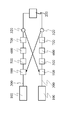
まず、本願発明の実施例1について図1乃至図6を参酌しつつ説明する。
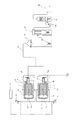
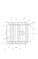
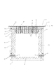
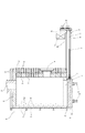
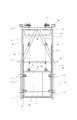
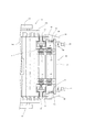
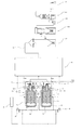
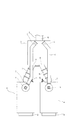
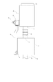
なお、図1は本願発明に係る廃タイヤの処理システムの一実施例の全体構成を示すためのフロー図である。図2乃至図6は、同実施例のシステムの処理炉の説明図であり、図2は概略的平面図、図3は図2のA−A線端面図、図4は概略的断面側面図、図5は概略的背面図、図6は要部拡大平面図である。
First, a first embodiment of the present invention will be described with reference to FIGS.
FIG. 1 is a flowchart for showing the overall configuration of an embodiment of a waste tire processing system according to the present invention. 2 to 6 are explanatory views of the processing furnace of the system of the embodiment, FIG. 2 is a schematic plan view, FIG. 3 is an end view taken along line AA of FIG. 2, and FIG. 5 is a schematic rear view, and FIG. 6 is an enlarged plan view of a main part.
まず、本実施例の処理システムの全体構成について説明すると、本システムは、図1に示すように、廃タイヤTから乾留ガスを発生させるべく廃タイヤTを密封状態で収容する複数(本実施例においては二つ)の処理炉100と、複数の処理炉100に接続され乾留ガスを供給する供給路300と、該供給路300の下流側に接続され、処理炉100において発生した乾留ガスを液状ガスに圧縮してガスボンベ等の液状ガス容器に充填する液状ガス充填機200とを備えている。
First, the overall configuration of the processing system of the present embodiment will be described. As shown in FIG. 1, the present system includes a plurality of (this embodiment) that accommodates the waste tire T in a sealed state so as to generate dry distillation gas from the waste tire T. 2) two
この供給路300には、通過する気体中に含まれる粉塵、硫黄化物等の不純物を除去する不純物除去手段600,700、及び、この不純物除去手段600,700の上流側に設けられ通過する気体の温度を急冷する冷却手段500が設けられている。具体的には、供給路300には、該処理炉100から排出されたガスを冷却する冷却塔500(冷却手段)と、該冷却塔500の下流側に設けられ冷却塔500から排出される排ガスから粉塵を取り除くためのバグフィルタ600(不純物除去手段600,700)と、該バグフィルタ600の下流側に設けられバグフィルタ600から排出れる排ガスから硫黄化合物を除去して大気に放出する硫黄除去装置700(不純物除去手段600,700)とを備えている。
In this
前記硫黄除去装置700は、バグフィルタ600から排出されたガスを水と接触させることにより、ガス中の硫黄加工物成分を除去するように設けられている。また、バグフィルタ600は、冷却塔500によって冷却されたガスから粉塵などを除去するフィルタを有している。ここで、この硫黄除去装置700とバグフィルタ600とを連結するガス流路には、下流側に排ガスを吸引する(バグフィルタ600側が負圧となるように)ブロア800が設けられている。
The
また、冷却塔500は、処理炉100から排出されるガスを塔内に導入して、これに冷水を噴射することにより、該ガスを冷却するように設けられている。本実施例においては、冷却塔500は、処理炉100から排出される300〜350度程度のガスを200度以下に急冷するように設けられている。
The
前記複数の処理炉100には、それぞれ、供給路300との接続口において、開閉弁111が設けられており、この開閉弁111は、制御手段(図示省略)によって開閉が制御されている。詳述すると、各開閉弁111は、乾留ガス発生時およびその後灰化にまで至らしめる(以下、乾留後の灰化に至る過程を「置き火」ということがある)までにおいては開放され、灰化終了後で且つ乾留開始前の廃タイヤの搬入・搬出時において閉塞されるように制御されている。
Each of the plurality of
次に、前記処理炉100の構成について説明する。
本実施例の処理炉100は、炉内において廃タイヤTを乾留し、その後置き火を行い、灰化に至らしめものであるが、該処理炉100は、炉本体がフレーム101と該フレーム101によって支持される耐火物102とから構成されており、炉内がレンガ等の耐火物102によって周囲を囲まれて構成されている。
Next, the configuration of the
The
前記耐火物102は、その周囲のフレーム101によって支持されており、特に上壁を構成する耐火物は、フレーム101に固定される鉄板103に設けられた略Y字状の支持金具104によって支持されている。なお、かかる構成は、鉄板103に支持金具104を溶接した後に、この鉄板103の上に粘土状の耐火物を積層して固化せしめることにより得ることができる。
The refractory 102 is supported by a
また、該処理炉100は、前記供給路300に接続されるガス送出口110を有し、該ガス送出口110は、既述のように廃タイヤTから得られる乾留ガスを前記供給路300に送給するとともに、置き火時に発生する排ガスも供給路300に排出するものである。また、この処理炉100のガス送出口110には、前述のように制御手段によって開閉が制御される開閉弁111が設けられている。
Further, the
また、処理炉100には、炉内に空気を供給する空気供給手段140,150が設けられており、該空気供給手段140,150により供給される空気量は制御手段(図示省略)によって制御されている。また、処理炉100は、複数種類の空気供給手段140,150を有しており、具体的には、炉内の下部側から空気を供給する複数の下部供給口140と、炉内の上部側から空気を供給する複数の上部供給口150とを有している。
The
また、処理炉100は、炉内の温度を測定する温度検知手段(図示省略)が設けられており、該温度検知手段の温度によって制御手段は、前記空気供給手段140,150による空気の供給量を調整している。
The
前記上部供給口150は、処理炉100の上壁に設けられており、この上部供給口150は、耐火物102および鉄板103を貫通する上部パイプ151の一端が炉内に表出することにより構成されており、この上部パイプ151の他端が空気供給管路152に接続されている。この空気供給管路152は、エアブロア160に接続され二つに分岐された主管152aと、この主管152aから三つに分岐された幹管152bと、この幹管152bから分岐され前記上部パイプ151が接続される枝管152cとから構成されている。また、主管152aには、制御手段(図示省略)によって開閉が制御される開閉弁111(図示省略)が設けられており、この開閉弁111は、乾留時に閉塞され、置き火時には開放するように制御されている。つまり、上部供給口150は、乾留時には空気を供給せず、置き火時に空気を供給するように設けられている。
The
また、前記下部供給口140は、処理炉100の側壁の下側に形成されており、下部供給口140は、側壁を構成する耐火物102を貫通する下部パイプ141の一端が炉内に表出することにより構成されている。この下部パイプ141は、下部用の空気供給管路(図示省略)に接続されており、この空気供給管路は、前記エアブロア160に接続されている。なお、このエアブロア160は空気の供給量を制御手段によって制御されている。また、前記下部用の空気供給管路にも開閉弁(図示省略)が設けられており、炉内の温度が一定温度以上となった場合には、該開閉弁が閉塞されるように制御手段によって制御されている。
The
また、処理炉100の上壁には、蓋によって閉塞された爆発安全孔105が形成されている。さらに、処理炉100には、廃タイヤTが乾留可能な温度まで上昇させるための着火用バーナ106が設けられている。なお、着火用バーナ106としては天然ガスバーナが好適に用いられる。また、この着火用バーナ106には、エアブロア202によって空気が供給されている。また、図1における107は、非常時に炉内に窒素ガスを供給するための窒素ガス供給装置である。
In addition, an
また、処理炉100は、廃タイヤTを炉内に搬入するための開口130と該開口130を閉塞するための蓋体400を有しており、該蓋体400は、炉本体に対してスライド可能に設けられているとともに、クランプ手段420によって炉本体側に圧接されるように設けられている。
Further, the
より具体的に説明すると、処理炉100は、炉内に廃タイヤTを搬入するための開口130が、ガス送出口110に対向する側壁に設けられており、該開口130を閉塞するための蓋体400は、上下動手段410によって上下動するように設けられ、下部側に移動した際にクランプ手段420によって炉本体側に圧接されるように設けられている。ここで、クランプ手段420は、炉本体のフレーム101に固定されたクランプ用支持金具421によって支持されている。
More specifically, in the
また、前記蓋体400は、格子状に設けられたフレーム401と、該フレーム401に取付けられた耐火物402とから構成されており、前記クランプ手段420によって該フレーム401が押圧されることにより、炉内を密閉できるように設けられている。
In addition, the
また、蓋体400には、その上部二箇所にワイヤ430が取付けられる吊り下げ用金具403が固着されており、該ワイヤ430によって上方に吊り上げられるように設けられている。
In addition, a hanging metal fitting 403 to which a
また、炉本体のフレーム101には柱部材440が固定されており、該柱部材440の上部には前記蓋体400を上部に引き上げるための前記上下動手段としての電動機410が取付けられている。より詳述すると、前記炉本体のフレーム101には一対の柱部材440が固定され、この一対の柱部材440の上部に連結フレーム450が固定されており、また、該連結フレーム450には、炉本体のフレーム101に一端が固定された補強フレーム460の他端が固定されている。
Further, a
また、連結フレーム450には、前記電動機410および該電動機410によって回転される回転ローラー415が左右一対に裁置固定されている。該左右一対の回転ローラー415は、それぞれ前後二つ設置されており、連結フレーム450に取付けられたローラー支持具によって回転可能に軸支されている。ここで、電動機410は、その出力軸にスプロケット411が取付けられ、また、回転ローラー415の軸にもスプロケット416が取付けられ、このスプロケット411,416同士にチェーン418が巻回され、回転力が伝達されるよう設けられている。また、前記回転ローラー415の外周に前記ワイヤ430が引っ掛けられており、回転ローラー415の回転により蓋体400が上下動するように設けられている。また、前記ワイヤ430の他端には、カウンターウェイト470が取付けられており、蓋体400とのバランスがとられている。
In addition, the
また、前記蓋体400には両側にローラーからなる突起404が設けられており、前記柱部材440には該突起404が係合可能な案内レール441が設けられている。ここで、案内レール441は、蓋体400が最下方に位置した際(開口130の閉塞位置に位置する際)には、前記突起404との係合が解除されるように設けられており、蓋体400が上昇する際に案内レール441に突起404が係合して安定した状態で蓋体400を上昇できるように設けられている。
The
次に、上記処理システムによる廃タイヤの処理方法について以下説明する。 Next, a waste tire processing method using the above processing system will be described below.
まず、一方の処理炉100において、蓋体400を上昇させて開口130から炉内に廃タイヤTを搬入する。この搬入に際しては、多数の廃タイヤTをそのままの状態(粉砕などにしない状態)で、たとえばフォークリフト等により開口130から搬入する。
First, in one
炉内に廃タイヤTを搬入した後に、蓋体400を下降せしめてクランプ手段420によって蓋体400を炉本体側に押圧せしめて炉内を密閉する。なお、この蓋体400の上下動に際しては、蓋体400が案内手段441によって案内されるので的確に上下動することができる。
After the waste tire T is carried into the furnace, the
上述のように蓋体400により炉内が密閉された後に、着火用バーナ106によって温度を上昇させつつ、下部供給口140から空気を供給する。なお、この供給開始時の空気量は、収容されたタイヤを焼却するために必要な理論空気量3〜4(完全燃焼に必要な空気量が10)で供給されている。
After the inside of the furnace is sealed by the
そして、処理炉100内が一定温度(250℃程度)となると、廃タイヤTの乾留が開始されるが、このように、炉内の温度が一定以上となった際に、下部供給口140から供給される空気量を、理論空気量0.2〜0.3程度に制御する。なお、着火用バーナ106は炉内が一定温度以上となった後にOFF状態としている。また、上部供給口150は、この乾留開始時には閉塞されている(空気を供給しない)。
Then, when the inside of the
また、乾留時において、炉内が一定温度(たとえば500度)以上となった場合には、制御手段は、前記下部供給口140からの空気供給を制御する。具体的には、一定温度以上となった場合には、一度、下部供給口140からの空気供給を停止して、その後、予定する空気量(理論空気量0.2〜0.3)よりも少ない空気を供給し、一定温度(たとえば500度)以下となった場合に、前記正常運転(理論空気量0.2〜0.3の空気供給)を再開する。また、炉内が一定温度(たとえば250度)以下となった場合には、制御手段は、下部供給口140からの空気供給を正常運転よりも多い空気を供給し、一定温度(たとえば250度)以上となった場合に、前記正常運転(理論空気量0.2〜0.3の空気供給)を再開する。なお、エアブロア160を、時間に応じて空気の送給量を調整するように設けることも可能である。上述のように、供給する空気を調節することによって、廃タイヤTの乾留の速度や乾留ガスの量を的確に調節することができる。
When the inside of the furnace reaches a certain temperature (for example, 500 degrees) or more during dry distillation, the control means controls the air supply from the
また、上記のように廃タイヤTから乾留ガスが発生している際には、ガス送給路310の開閉弁111は開放されており、発生した乾留ガスは、ガス送出口110から供給路300に供給される。また、上記のように乾留ガス発生時においては下流側に設けられたブロア800をON状態としておく。これにより、供給路300の上流側が処理炉100よりも負圧となるため、処理炉100へ乾留ガスの逆流を防止することができる。
Further, when dry distillation gas is generated from the waste tire T as described above, the on-off
また、上記乾留を開始して一定時間経過後(たとえば11.5時間経過後)、つまりは、その乾留が終了する一定時間(30分)前に、他の処理炉100において、乾留のために着火バーナー106が着火して、炉内の温度が上昇する。そして、他の処理炉100が一定の時間(約30分)後に一定温度(250度)以上となり、これにより、この他の処理炉100において乾留ガスが発生する。このように、一の処理炉100による乾留が終了する際には、他の処理炉100による乾留を開始することができるため、供給路300に乾留ガスを連続的に供給することができる。
Further, after a certain period of time has elapsed since the start of the carbonization (for example, after a period of 11.5 hours), that is, before a certain period of time (30 minutes) when the carbonization ends, The
また、上記乾留を開始して一定時間経過(たとえば12時間経過)して、乾留ガスの発生が終了した際に、下部供給口140のみにならず、上部供給口150からの空気送給を開始して、置き火を開始する。このように、上部供給口150からも空気供給を行うことにより、この処理炉100内の廃タイヤTの灰化に必要な空気量(たとえば理論空気量10)を供給することができ、乾留が終了した廃タイヤTを完全に灰化することができる。なお、乾留時において上部供給口150が油分などによって閉塞されていても、この供給口150は下方に向けて設けられているため、供給される空気圧によって油分などを容易に除去することができる。
In addition, when a certain period of time has elapsed (for example, 12 hours have elapsed) since the start of the carbonization, and when the generation of carbonization gas is completed, not only the
上記のように廃タイヤTを灰化する際に発生した排ガスは、ガス送出口110を介して前記供給路300に排出されることになる。この供給路300に排出された排ガスは、乾留ガスとともに、冷却塔500において200度程度に急冷された後に、バグフィルタ600により粉塵を除去され、硫黄除去装置700によって硫黄化合物が除去された後に、液状ガス充填機200に供給されることになる。
The exhaust gas generated when the waste tire T is ashed as described above is discharged to the
そして、液状ガス充填機200においては、供給された気体中の乾留ガスを液状に圧縮して液状ガス容器に充填するとともに、その他の成分のものは大気に放出することになる。ここで、大気に放出されるガスは、既述の不純物除去手段600,700に不純物が除去されているため、不純物の残存量のきわめて少ないものである。
In the liquid
また、上記のような灰化が終了し、炉内の温度が一定以下となった後に、ガス供給路300の開閉弁111を閉塞して、この処理炉100の蓋体400を上昇して、灰化した廃タイヤTを開口130から除去して、再度既述のように廃タイヤTを搬入して、他方の処理炉100による乾留終了の際には乾留を開始できるように準備しておき、他方の処理炉100による乾留が終了する際に、既述のような乾留作業を開始することになる。
Further, after the ashing as described above is finished and the temperature in the furnace becomes below a certain level, the on-off
次に、本願発明に係る処理システムの他の実施例(実施例2)について、図7乃至図9を参酌しつつ、以下、説明する。
なお、図7は、本願発明に係る廃タイヤの処理システムの実施例2の全体構成を示すためのフロー図である。図8および図9は、同実施例のシステムの処理炉100およびガス混合室310の説明図で、図8は概略的平面図、図9は概略的側面図である。また、実施例1と同様の構成及び機能を有する部分については、その詳細な説明を省略する。
Next, another embodiment (embodiment 2) of the processing system according to the present invention will be described below with reference to FIGS.
FIG. 7 is a flowchart for illustrating the overall configuration of the second embodiment of the waste tire processing system according to the present invention. 8 and 9 are explanatory views of the
実施例2の処理システムも、実施例1と同様に、複数の処理炉100と、該処理炉100において発生した乾留ガスを液状ガスに圧縮して液状ガス容器に充填する液状ガス充填機200と、複数の処理炉100および液状ガス充填機200に接続され乾留ガスを供給する供給路300とを備え、該供給路300に不純物除去手段600,700、及び、冷却手段500が設けられている。
Similarly to the first embodiment, the processing system according to the second embodiment also includes a plurality of
この実施例2の処理システムにあっては、前記処理炉100には、発生した乾留ガスを供給路300に供給するガス送出口110、および、置き火時に発生する排ガスを供給路300に供給する排出口120がそれぞれ設けられており、このガス送出口110および排出口120がそれぞれ供給路300に接続されている。
In the processing system of the second embodiment, the
また、供給路300には、前記複数の処理炉100のガス送出口110および排出口120が接続されるガス混合室310が設けられており、つまり、各処理炉100において発生する乾留ガス及び排ガスは該ガス混合室310に供給されるように設けられている。
Further, the
また、処理炉100の排出口120は処理炉100の上部に設けられ、また、混合室310の排出口120との接続口311は、混合室310の上部に設けられており、これにより、混合室310内の乾留ガス(空気よりも比重が重い乾留ガス)が、排出口120から処理炉100に逆流しないように設けられている。なお、ガス送出口110は、処理炉100の側方(蓋体の対向する側面)に形成されている。
Moreover, the
具体的に説明すると、処理路100の上方に形成された排出口120と、混合室310の上方に形成された排ガス接続口311とは、処理路100及び混合室310の上方に配された排ガス接続管312によって接続されている。また、混合室310には、前記ガス送出口110に接続される乾留ガス接続口313が、処理路110と対向する側壁に形成されており、この乾留ガス接続口313とガス送出口110とがガス接続管314によって接続されている。また、混合室310には、下流側(冷却塔500側)にガスを送給するための送給口315が、前記乾留ガス接続口313の形成された側壁と対向する側壁に形成されている。また、前記排ガス接続口311は、この送給口315に近接する上壁に設けられており、このガス接続口311から混合室310内に流入した排ガスが送給口315から下流側に送給されやすいように設けられている。
More specifically, the
また、ガス供給口110および排出口120には、何れも開閉弁111,121が設けられている。このように、開閉弁111,121が処理炉100の炉内に近接して設けられているため、炉内の温度制御などが容易に行い得るとともに、タイヤ処理時にタール等のピッチが流路にこびりつく弊害を防止することもできる。
In addition, the
また、この開閉弁111,121は、制御手段(図示省略)によって、乾留ガス発生時においては、ガス送出口110の開閉弁111が開放され、排出口120の開閉弁121が閉塞され、一方、乾留ガス発生終了後においては、ガス送出口110の開閉弁111が閉塞され、排出口120の開閉弁121が開放されるように制御されている。なお、灰化終了後で且つ乾留開始前における廃タイヤの搬入・搬出時には、各開閉弁111,121は何れも、閉塞されるように制御されている。
The on-off
次に、本願発明に係る処理システムの他の実施例(実施例3)について、図10を参酌しつつ、以下、説明する。
なお、図10は、本願発明に係る廃タイヤの処理システムの実施例3の全体構成を示すための概略的フロー図である。また、実施例1または実施例2と同様の構成及び機能を有する部分については、その詳細な説明を省略する。
Next, another embodiment (third embodiment) of the processing system according to the present invention will be described below with reference to FIG.
FIG. 10 is a schematic flowchart for illustrating the overall configuration of the third embodiment of the waste tire processing system according to the present invention. Detailed descriptions of portions having the same configurations and functions as those of the first or second embodiment are omitted.
実施例3の処理システムも、実施例1と同様に、複数の処理炉100と、該処理炉100において発生した乾留ガスを液状ガスに圧縮して液状ガス容器に充填する液状ガス充填機200とを備えている。そして、実施例3の処理システムは、各処理炉100に対応した供給路300を有している。そして、該供給路300には、それぞれ、通過する気体を加熱する加熱手段900と、該加熱手段900の下流側に設けられ通過する気体の温度を急冷する冷却手段500と、該冷却手段500の下流側に設けられ通過する気体中に含まれる粉塵、硫黄化物等の不純物を除去する不純物除去手段600,700とが設けられている。なお、実施例3において、冷却手段500、不純物除去手段600,700は、実施例1と同様のものを利用することが可能である。
Similarly to the first embodiment, the processing system of the third embodiment also includes a plurality of
また、前記供給路300は、下流側に前記液状ガス充填機200が接続されている。また、該供給路300には、分岐弁320が設けられており、該分岐弁320は、一方が前記液状ガス充填機200側に乾留ガスを供給するように設けられている。ここで、該分岐弁320は、前記不純物除去手段600,700の下流側に配置されている。
The
また、前記供給路300に設けられた加熱手段900は、他の供給路300の乾留ガスを熱源とするように設けられている。具体的には、一の供給路300の加熱手段900は、他の供給路300の分岐弁320において分岐され供給される乾留ガスを燃焼することにより、内部の気体を加熱できるように設けられている。なお、該加熱手段900に、他の供給路300の乾留ガス以外の熱源を利用できるように設けることも適宜設計変更可能な事項である。
The heating means 900 provided in the
なお、上記各実施例は上記構成からなるものであったが、本願発明はこれに限定されるものではなく、本願発明の意図する範囲内において適宜設計変更可能である。 In addition, although each said Example consisted of the said structure, this invention is not limited to this, A design change is possible suitably within the range which this invention intends.
つまり、上記実施例のシステムは、不純物除去手段600,700として、バグフィルター600及び硫黄化合物除去手段700を備えたものについて説明したが、本願発明にあっては、その他の不純物除去手段を採用することも適宜設計変更可能な事項である。
That is, the system of the above embodiment has been described as the impurity removing means 600, 700 including the
また、処理炉100が二つのものについてのみ説明したが、処理炉100の個数も上記実施例に限定されるものではなく、三個以上の処理炉100を有するものであっても、本願発明の意図する範囲内である。
Although only two processing
また、上記実施例においては、一の処理炉100において乾留終了前に他の処理炉100の乾留開始の作業を開始し、他の処理炉100の乾留が開始されても一の処理炉100の乾留を継続して行うものであったが、たとえば、他の処理炉100の乾留が開始した際に一の処理炉100において置き火を開始する(置き火に必要な空気量を供給する)ことも可能である。但し、一の処理炉100における乾留終了時には、他の処理炉100において乾留が開始されていることが好ましく、これにより、連続的に液状ガス充填機200に乾留ガスを供給することができる。
Moreover, in the said Example, the operation | work of the dry distillation start of the
また、上記実施例においては、供給路300の下流側に液状ガス充填機200を設置したものについて説明したが、本願発明はこれに限定されるものではなく、たとえばボイラー等を設置することも適宜設計変更可能な事項である。
In the above embodiment, the liquid
T タイヤ
100 処理炉
101 フレーム
102 耐火物
103 鉄板
104 支持金具
105 爆発安全孔
106 着火用バーナ
107 窒素ガス供給装置
110 ガス送出口
111 開閉弁
120 排出口
121 開閉弁
130 開口
140 下部供給口(空気供給手段)
141 下部パイプ
150 上部供給口(空気供給手段)
151 上部パイプ
152 空気供給管路
152a主管
152b幹管
152c枝管
160 エアブロア
200 ガス充填機
300 供給路
310 ガス混合室
311 排ガス接続口
312 排ガス接続管
313 乾留ガス接続口
314 乾留ガス接続管
315 送給口
400 蓋体
401 フレーム
402 耐火物
403 吊り下げ用金具
404 突起
410 電動機
411 スプロケット
415 回転ローラー
416 スプロケット
418 チェーン
420 クランプ手段
421 支持金具
430 ワイヤ
440 柱部材
441 案内レール
450 連結フレーム
460 補強フレーム
470 カウンターウェイト
500 冷却塔(冷却手段)
600 バグフィルタ(不純物除去手段)
700 硫黄除去装置(不純物除去手段)
800 ブロア
141
151
600 Bag filter (impurity removal means)
700 Sulfur removal equipment (impurity removal means)
800 blowers
Claims (18)
この複数の処理炉に接続され乾留ガスを下流側に供給する供給路とを備え、
該供給路には、通過する気体中に含まれる粉塵、硫黄化物等の不純物を除去する不純物除去手段が設けられていることを特徴とする
タイヤ等の廃棄物の処理システム。 A plurality of treatment furnaces for containing waste in a sealed state so as to generate dry distillation gas from waste such as tires;
A supply path connected to the plurality of processing furnaces to supply dry distillation gas downstream,
A waste treatment system for a tire or the like, characterized in that the supply path is provided with an impurity removing means for removing impurities such as dust and sulfur contained in the passing gas.
この複数の処理炉にそれぞれ接続され乾留ガスを下流側に供給する複数の供給路とを備え、
各供給路には供給路内の気体を一定温度以上に加熱する加熱手段が設けられており、
一の供給路の加熱手段は、他の供給路の乾留ガスの燃焼により加熱するように設けられていることを特徴とする
タイヤ等の廃棄物の処理システム。 A plurality of treatment furnaces for containing waste in a sealed state so as to generate dry distillation gas from waste such as tires;
A plurality of supply passages connected to the plurality of processing furnaces respectively to supply dry distillation gas downstream,
Each supply path is provided with heating means for heating the gas in the supply path to a certain temperature or higher,
A waste treatment system for a tire or the like, wherein the heating means of one supply path is provided so as to be heated by combustion of dry distillation gas in another supply path.
前記供給路には、前記加熱手段の下流側に、通過する気体を冷却する冷却手段が設けられていることを特徴とする
タイヤ等の廃棄物の処理システム。 A processing system according to claim 2, wherein
A waste treatment system for a tire or the like, wherein the supply path is provided with cooling means for cooling the gas passing therethrough on the downstream side of the heating means.
前記供給路には、前記不純物除去手段の上流側に、通過する気体を冷却する冷却手段が設けられていることを特徴とする
タイヤ等の廃棄物の処理システム。 A processing system according to any one of claims 1 to 3,
The waste supply system for a tire or the like, wherein the supply path is provided with cooling means for cooling the gas passing therethrough upstream of the impurity removing means.
前記処理炉に空気を供給する乾留用空気供給手段が設けられており、該乾留用空気供給手段により乾留時に供給される空気量が制御手段によって制御されていることを特徴とする
タイヤ等の廃棄物の処理システム。 A processing system according to any one of claims 1 to 4,
Disposal of tires, etc., characterized in that dry distillation air supply means for supplying air to the processing furnace is provided, and the amount of air supplied during dry distillation by the dry distillation air supply means is controlled by the control means Material processing system.
複数の処理炉のうち、一の処理炉において乾留ガスが発生せずに灰化を行わせている際に、他の少なくとも一の処理炉において乾留ガスが発生するように制御されていることを特徴とする
タイヤ等の廃棄物の処理システム。 A processing system according to any one of claims 1 to 5,
Among the plurality of processing furnaces, when ashing is performed without generating dry distillation gas in one processing furnace, it is controlled so that dry distillation gas is generated in at least one other processing furnace. A waste treatment system such as a tire.
前記供給路には、処理炉内の排ガスが供給されるように設けられていることを特徴とする
タイヤ等の廃棄物の処理システム。 A processing system according to any one of claims 1 to 6,
A waste treatment system for a tire or the like, characterized in that the supply passage is provided so as to be supplied with exhaust gas in a treatment furnace.
前記処理炉の上部には、前記処理炉に空気を供給するための上部供給口が設けられており、該上部供給口からの空気供給は、制御手段によって制御されていることを特徴とする
タイヤ等の廃棄物の処理システム。 A processing system according to any one of claims 1 to 7,
An upper supply port for supplying air to the processing furnace is provided at an upper portion of the processing furnace, and air supply from the upper supply port is controlled by a control unit. Waste disposal system.
前記処理炉と供給路との接続口の付近には、開閉弁が設けられていることを特徴とする
タイヤ等の廃棄物の処理システム。 A processing system according to any one of claims 1 to 8,
A waste treatment system for tires or the like, wherein an on-off valve is provided in the vicinity of a connection port between the treatment furnace and the supply path.
複数の処理炉のうち少なくとも一つの処理炉において廃棄物を密封状態で収容して乾留ガスを発生させて、
該処理炉において発生した乾留ガスを、複数の処理炉において共通する供給路を介して下流側に供給する際に、供給路に設けられた不純物除去手段によって粉塵、硫黄化物等の不純物を除去することを特徴とするタイヤ等の廃棄物の処理システム。 A method of treating waste such as tires in a treatment furnace,
Storing waste in a sealed state in at least one of the plurality of processing furnaces to generate dry distillation gas;
When supplying the dry distillation gas generated in the processing furnace to the downstream side through a common supply path in the plurality of processing furnaces, impurities such as dust and sulfurized substances are removed by impurity removing means provided in the supply path. A system for treating waste such as tires.
複数の処理炉のうち少なくとも一つの処理炉において廃棄物を密封状態で収容して乾留ガスを発生させて、
該処理炉において発生した乾留ガスを、各処理炉に対応した供給路を介して下流側に供給する際に、他の供給路の乾留ガスにより加熱される加熱手段によって、供給路内の気体を一定温度以上に加熱するように設けられていることを特徴とする
タイヤ等の廃棄物の処理方法。 A method of treating waste such as tires in a treatment furnace,
Storing waste in a sealed state in at least one of the plurality of processing furnaces to generate dry distillation gas;
When the dry distillation gas generated in the processing furnace is supplied to the downstream side through the supply path corresponding to each processing furnace, the gas in the supply path is changed by the heating means heated by the dry distillation gas of the other supply path. A method for treating waste such as tires, which is provided so as to be heated to a predetermined temperature or higher.
前記供給路において、前記加熱手段の下流側に設けられた冷却手段によって、通過する気体を冷却することを特徴とする
タイヤ等の廃棄物の処理方法。 The processing method according to claim 11, comprising:
A method for treating waste such as tires, characterized in that in the supply path, the passing gas is cooled by a cooling means provided on the downstream side of the heating means.
前記供給路において、前記不純物除去手段の上流側に設けられた冷却手段によって、通過する気体を冷却することを特徴とする
タイヤ等の廃棄物の処理方法。 A processing method according to any one of claims 10 to 12,
A method for treating waste such as tires, characterized in that in the supply path, the passing gas is cooled by a cooling means provided on the upstream side of the impurity removing means.
前記処理炉において乾留ガスを発生させる際に、乾留用空気供給手段により炉内に所望の空気を制御手段で制御しつつ供給することを特徴とする
タイヤ等の廃棄物の処理方法。 A processing method according to any one of claims 10 to 13,
A method for treating waste such as tires, wherein when generating carbonization gas in the processing furnace, desired air is supplied into the furnace by the air supply means for carbonization while being controlled by the control means.
処理炉において乾留ガスが発生しなくなった後に、その廃棄物を灰化に至らしめ、
前記複数の処理炉のうち、一つの処理炉において乾留ガスが発生せずに灰化に至らしめている際に、他の少なくとも一の処理炉において乾留ガスが発生するように制御することを特徴とする
タイヤ等の廃棄物の処理方法。 A processing method according to any one of claims 10 to 14,
After no carbonization gas is generated in the treatment furnace, the waste is incinerated.
Among the plurality of processing furnaces, when the ashing is achieved without generating the dry distillation gas in one processing furnace, control is performed so that the dry distillation gas is generated in at least one other processing furnace. Waste disposal methods such as tires.
処理炉において乾留ガスが発生しなくなった後に、その廃棄物を灰化に至らしめ、この灰化に際して発生する排ガスを前記供給路に供給していることを特徴とする
タイヤ等の廃棄物の処理方法。 A processing method according to any one of claims 10 to 15,
After the carbonization gas is no longer generated in the treatment furnace, the waste is brought to ashing, and the exhaust gas generated during the ashing is supplied to the supply path, so that the processing of the waste such as tires is performed. Method.
処理炉において乾留ガスが発生しなくなった後に、その廃棄物を灰化に至らしめ、この灰化に際して処理炉の上部に設けられた上部供給口から空気を供給することを特徴とする
タイヤ等の廃棄物の処理方法。 A processing method according to any one of claims 10 to 16, wherein
After dry distillation gas is no longer generated in the processing furnace, the waste is brought to ashing, and air is supplied from the upper supply port provided in the upper part of the processing furnace at the time of the ashing, etc. Waste disposal method.
処理炉において乾留ガスが発生しなくなった後に、その廃棄物を灰化に至らしめた後に、処理炉と供給路との接続口の付近に設けられた開閉弁を閉塞状態とすることを特徴とする
タイヤ等の廃棄物の処理方法。 A processing method according to any one of claims 10 to 17,
After the dry distillation gas is no longer generated in the processing furnace, the waste is brought to ashing, and then the on-off valve provided near the connection port between the processing furnace and the supply path is closed. Waste disposal methods such as tires.
Priority Applications (1)
| Application Number | Priority Date | Filing Date | Title |
|---|---|---|---|
| JP2004106576A JP2005290178A (en) | 2004-03-31 | 2004-03-31 | Treating system of waste material, such as tire, and treating method of the same |
Applications Claiming Priority (1)
| Application Number | Priority Date | Filing Date | Title |
|---|---|---|---|
| JP2004106576A JP2005290178A (en) | 2004-03-31 | 2004-03-31 | Treating system of waste material, such as tire, and treating method of the same |
Publications (1)
| Publication Number | Publication Date |
|---|---|
| JP2005290178A true JP2005290178A (en) | 2005-10-20 |
Family
ID=35323483
Family Applications (1)
| Application Number | Title | Priority Date | Filing Date |
|---|---|---|---|
| JP2004106576A Pending JP2005290178A (en) | 2004-03-31 | 2004-03-31 | Treating system of waste material, such as tire, and treating method of the same |
Country Status (1)
| Country | Link |
|---|---|
| JP (1) | JP2005290178A (en) |
Cited By (2)
| Publication number | Priority date | Publication date | Assignee | Title |
|---|---|---|---|---|
| JP2011522200A (en) * | 2008-05-14 | 2011-07-28 | レオン エンジニアリング エス.ピー.エイ. | Material oxidation process and related equipment |
| WO2014030694A1 (en) * | 2012-08-23 | 2014-02-27 | YAMASAKI Sadayoshi | System for recycling waste plastics and recycling method |
-
2004
- 2004-03-31 JP JP2004106576A patent/JP2005290178A/en active Pending
Cited By (2)
| Publication number | Priority date | Publication date | Assignee | Title |
|---|---|---|---|---|
| JP2011522200A (en) * | 2008-05-14 | 2011-07-28 | レオン エンジニアリング エス.ピー.エイ. | Material oxidation process and related equipment |
| WO2014030694A1 (en) * | 2012-08-23 | 2014-02-27 | YAMASAKI Sadayoshi | System for recycling waste plastics and recycling method |
Similar Documents
| Publication | Publication Date | Title |
|---|---|---|
| JPH10263357A (en) | Gas scrubber and gas treatment by utilizing the same | |
| US4050900A (en) | Incineration apparatus | |
| KR20050004647A (en) | Device and method for waste processing using Plasma pyrolysis | |
| CN102667342A (en) | Gas barrier | |
| US4204979A (en) | Method of processing activated carbon | |
| US4202282A (en) | Method of incineration | |
| JP2005290178A (en) | Treating system of waste material, such as tire, and treating method of the same | |
| KR101415450B1 (en) | Incineration device for solid wastes | |
| JP2008545115A (en) | Vacuum incinerator for waste disposal and vacuum maintenance method for incinerator | |
| US20050077658A1 (en) | Fume treatment system and method | |
| JPWO2005019727A1 (en) | Tire and other waste treatment system, method for the same, and tire and other waste treatment furnace | |
| JP3377359B2 (en) | Waste treatment equipment | |
| WO2011157913A1 (en) | Flue-gas production and treatment plant | |
| JPH06134434A (en) | Apparatus for treating waste and treatment method with the same | |
| JP4045176B2 (en) | Purification equipment for contaminated soil | |
| JP2006160860A (en) | Continuous carbonization equipment | |
| JP2006300504A (en) | Apparatus and method for incinerating waste contained in a drum | |
| JP5134749B2 (en) | Waste solid fuel incineration method and equipment | |
| JP3303188B2 (en) | Dioxin removal device in ash | |
| JPH07116628A (en) | Incineration ash heat treatment equipment | |
| JP2008200544A (en) | Waste melting treatment method | |
| JP7399376B2 (en) | Heat treatment equipment and heat treatment method | |
| JP2003106511A (en) | Horizontal rotary furnace equipment | |
| JP3755055B2 (en) | Melt treatment apparatus and waste treatment system including the same | |
| JP2013176713A (en) | Melting detoxification apparatus for asbestos-containing waste product, and treatment method for the same |