JP2005290106A - Photosensitive resin composition for optical waveguide formation, and optical waveguide formed using the same - Google Patents
Photosensitive resin composition for optical waveguide formation, and optical waveguide formed using the same Download PDFInfo
- Publication number
- JP2005290106A JP2005290106A JP2004104549A JP2004104549A JP2005290106A JP 2005290106 A JP2005290106 A JP 2005290106A JP 2004104549 A JP2004104549 A JP 2004104549A JP 2004104549 A JP2004104549 A JP 2004104549A JP 2005290106 A JP2005290106 A JP 2005290106A
- Authority
- JP
- Japan
- Prior art keywords
- optical waveguide
- meth
- resin composition
- acrylate
- photosensitive resin
- Prior art date
- Legal status (The legal status is an assumption and is not a legal conclusion. Google has not performed a legal analysis and makes no representation as to the accuracy of the status listed.)
- Granted
Links
Images
Landscapes
- Optical Integrated Circuits (AREA)
- Addition Polymer Or Copolymer, Post-Treatments, Or Chemical Modifications (AREA)
Abstract
【課題】 前処理を施さなくとも塗工性に優れる塗膜を形成できると同時に、基板との密着性にも優れた光導波路形成用感光性樹脂組成物を提供する。
【解決手段】 下記式(1)
【化1】
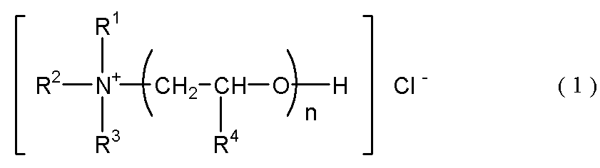
(式中、R1〜R3は炭素数1〜5のアルキル基であり、R4は水素原子又はメチル基であり、nは5〜50の数を表す。)
で示される化合物、
重合性化合物、及び
光重合開始剤
を含有する光導波路形成用感光性樹脂組成物;及びそれを用いた光導波路。
【選択図】 図1
PROBLEM TO BE SOLVED: To provide a photosensitive resin composition for forming an optical waveguide which can form a coating film having excellent coating properties without being subjected to pretreatment and at the same time has excellent adhesion to a substrate.
The following formula (1)
[Chemical 1]
(Wherein, R 1 to R 3 is an alkyl group of 1 to 5 carbon atoms, R 4 is a hydrogen atom or a methyl radical, n represents a number of 5-50.)
A compound represented by
A photosensitive resin composition for forming an optical waveguide containing a polymerizable compound and a photopolymerization initiator; and an optical waveguide using the same.
[Selection] Figure 1
Description
本発明は、光通信分野や光情報処理分野で用いられる光回路を作製するための光導波路形成用感光性樹脂組成物、及び該組成物を用いて作製される光導波路に関する。 The present invention relates to a photosensitive resin composition for forming an optical waveguide for producing an optical circuit used in the fields of optical communication and optical information processing, and an optical waveguide produced using the composition.
マルチメディア時代を迎え、光通信システムやコンピュータにおける情報処理の大容量化及び高速化の要求から、光を伝送媒体とする伝送システムが、公衆通信網、LAN(ローカルエリアネットワーク)、FA(ファクトリーオートメーション)、コンピュータ間のインターコネクト、家庭内配線等に使用されつつある。この伝送システムを構成する要素のうち、光導波路は、例えば、映画や動画等の大容量の情報伝達や光コンピュータ等を実現するための光デバイス、光電集積回路(OEIC)、光集積回路(光IC)等における基本構成要素である。そして、光導波路は、大量の需要があることから鋭意研究される一方、特に、高性能で低コストの製品が求められている。 In the multimedia era, in response to demands for large capacity and high speed information processing in optical communication systems and computers, transmission systems using light as a transmission medium are public communication networks, LAN (local area networks), FA (factory automation). ), Being used for interconnects between computers, home wiring, and the like. Among the elements constituting this transmission system, the optical waveguide is, for example, an optical device, an optical integrated circuit (OEIC), an optical integrated circuit (optical IC) and the like. Optical waveguides are intensively studied due to the large amount of demand, and in particular, high performance and low cost products are required.
光導波路としては、従来、石英系光導波路やポリマー系光導波路が知られている。
このうち、石英系光導波路は、伝送損失が低いという利点を有する反面、製造工程における加工温度が高いこと、及び、大面積のものを作製しがたいこと等のプロセス上の問題があった。
また、ポリマー系光導波路は、加工のし易さや材料設計の幅広さ等の利点を有することから、ポリメチルメタクリレートやポリカーボネート等のポリマー材料を用いたものが検討されてきた。しかし、一般に、ポリマー系光導波路は、耐熱性が劣るという問題がある。そのため、最近では、耐熱性及び伝送損失に優れるフッ素化ポリイミドの検討が盛んに行なわれている。
Conventionally known silica optical waveguides and polymer optical waveguides are known as optical waveguides.
Among these, the quartz-based optical waveguide has an advantage that the transmission loss is low, but has a problem in process such as high processing temperature in the manufacturing process and difficulty in manufacturing a large area.
Also, polymer-based optical waveguides have advantages such as ease of processing and wide material design. Therefore, those using polymer materials such as polymethyl methacrylate and polycarbonate have been studied. However, in general, a polymer-based optical waveguide has a problem that heat resistance is poor. Therefore, recently, fluorinated polyimides having excellent heat resistance and transmission loss have been actively studied.
ところが、ポリマー材料を用いた場合には、光導波路中のコア部を作製する際に、石英系光導波路と同様にドライエッチング処理を必要とするため、製造に要する時間が多大であるという問題がある。
このような状況下において、近年、フォトリソグラフィー性を付与したエポキシ系紫外線硬化樹脂等の光硬化性材料及び該材料を用いた光導波路が提案されている(例えば、特許文献1参照)。
However, when a polymer material is used, when the core portion in the optical waveguide is manufactured, a dry etching process is required as in the case of the silica-based optical waveguide. is there.
Under such circumstances, in recent years, a photocurable material such as an epoxy-based ultraviolet curable resin imparted with photolithography properties and an optical waveguide using the material have been proposed (for example, see Patent Document 1).
なお、従来の材料では、基板の材料(基材)の種類、表面状態によっては、塗工時に樹脂組成物の“はじき”や“むら”が生じ、均一な塗膜が得られないことがあった。そのため、材料塗布前に基板を前処理(プライマー処理等の化学処理、紫外線照射・プラズマ処理・オゾン処理等の物理処理)する必要があった。
さらに、はじき等の塗工性が良好であっても、基板との密着性が良好でないと、樹脂組成物が基板から剥がれ、伝送損失が大きくなってしまうため、光導波路形成用樹脂としての長期信頼性が損なわれるという問題点もあった。
In addition, with conventional materials, depending on the type of substrate material (base material) and the surface condition, “repelling” and “unevenness” of the resin composition may occur during coating, and a uniform coating film may not be obtained. It was. Therefore, it is necessary to pre-treat the substrate (chemical treatment such as primer treatment, physical treatment such as ultraviolet irradiation / plasma treatment / ozone treatment) before applying the material.
Furthermore, even if coating properties such as repellency are good, if the adhesion to the substrate is not good, the resin composition will be peeled off from the substrate and transmission loss will be increased. There was also a problem that reliability was impaired.
上記課題に鑑み、本発明は、前処理を施さなくとも塗工性に優れる塗膜を形成できると同時に、基板との密着性にも優れた光導波路形成用感光性樹脂組成物を提供することを目的とする。 In view of the above problems, the present invention provides a photosensitive resin composition for forming an optical waveguide that can form a coating film excellent in coatability without being subjected to pretreatment, and also has excellent adhesion to a substrate. With the goal.
上記目的を達成するため、本発明者らは、基板による樹脂組成物のはじき等を抑制しうる添加剤(界面活性剤)を鋭意探索した結果、特定構造を有する添加剤(界面活性剤)を材料中に添加することで前処理を施さなくともはじき等の塗工性に優れる塗膜を形成できると同時に、基板との密着性も良好であることを見出し本発明を完成させた。 In order to achieve the above-mentioned object, the present inventors have eagerly searched for an additive (surfactant) that can suppress the repelling of the resin composition by the substrate, and as a result, have found an additive (surfactant) having a specific structure. By adding it to the material, it was found that a coating film having excellent coating properties such as repelling can be formed without pretreatment, and at the same time, the adhesiveness with the substrate was found to be good, and the present invention was completed.
すなわち、本発明は、
[1]下記式(1)
で示される化合物、
重合性化合物、及び
光重合開始剤
を含有する光導波路形成用感光性樹脂組成物;
[2]前記式(1)で示される化合物を、重合性化合物100質量部に対して0.001〜10質量部含有する、上記[1]に記載の光導波路形成用感光性樹脂組成物;及び
[3]コア層及びクラッド層とを有する光導波路であって、該コア層及び該クラッド層のいずれか一方又は両方が、上記[1]又は[2]に記載の光導波路形成用感光性樹脂組成物からなる光導波路
を提供する。
That is, the present invention
[1] The following formula (1)
A compound represented by
A photosensitive resin composition for forming an optical waveguide comprising a polymerizable compound and a photopolymerization initiator;
[2] The photosensitive resin composition for forming an optical waveguide according to the above [1], which contains 0.001 to 10 parts by mass of the compound represented by the formula (1) with respect to 100 parts by mass of the polymerizable compound; And [3] an optical waveguide having a core layer and a clad layer, wherein either or both of the core layer and the clad layer are photosensitive for optical waveguide formation according to the above [1] or [2] An optical waveguide comprising a resin composition is provided.
本発明の光導波路形成用樹脂組成物は、上述の前処理を施さなくても、はじきが抑制され、均一な塗膜が得られる。そのため、安価に大面積での導波路作製が可能になる。
また、本発明の樹脂組成物から形成される塗膜は、基板との密着性が良好であるため、種々の環境条件下での保存においても長期信頼性に優れる光導波路を提供できる。
Even if the resin composition for forming an optical waveguide of the present invention is not subjected to the above pretreatment, the repelling is suppressed and a uniform coating film is obtained. Therefore, a waveguide with a large area can be manufactured at a low cost.
Moreover, since the coating film formed from the resin composition of this invention has favorable adhesiveness with a board | substrate, the optical waveguide excellent in long-term reliability can be provided also in the preservation | save on various environmental conditions.
以下、本発明を詳細に説明する。
A.光導波路形成用感光性樹脂組成物
本発明の光導波路形成用感光性樹脂組成物(以下、本発明の樹脂組成物という)は、下記式(1)
で示される化合物、
重合性化合物、及び
光重合開始剤
を含有することを特徴とする。
Hereinafter, the present invention will be described in detail.
A. Photosensitive resin composition for forming an optical waveguide The photosensitive resin composition for forming an optical waveguide of the present invention (hereinafter referred to as the resin composition of the present invention) is represented by the following formula (1).
A compound represented by
It contains a polymerizable compound and a photopolymerization initiator.
なお、本願明細書中において、本発明の樹脂組成物は、上記式(1)で示される化合物を含む硬化前の液状の形態と、上記式(1)で示される化合物を含む液状の組成物が硬化した形態の両方を包含する概念を有するものである。 In the specification of the present application, the resin composition of the present invention is a liquid composition containing a compound represented by the above formula (1) and a liquid form before curing and a compound represented by the above formula (1). Has a concept including both cured forms.
1.式(1)で示される化合物
本発明において用いられる、はじき等を抑制する作用を有する化合物は、下記式(1)
式(1)において、R1は、炭素数1〜5のアルキル基であり、好ましくは炭素数1〜3のアルキル基、特に好ましくはエチル基である。
R2は、炭素数1〜5のアルキル基であり、好ましくは炭素数1〜3のアルキル基、特に好ましくはメチル基である。
R3は、炭素数1〜5のアルキル基であり、好ましくは炭素数1〜3のアルキル基、特に好ましくはエチル基である。
R4は水素原子又はメチル基であり、好ましくはメチル基である。
nは5〜50の数を表し、好ましくは5〜45、より好ましくは15〜40である。
1. Compound represented by Formula (1) The compound used in the present invention and having an action of suppressing repellency is represented by the following formula (1).
In the formula (1), R 1 is an alkyl group having 1 to 5 carbon atoms, preferably an alkyl group having 1 to 3 carbon atoms, and particularly preferably an ethyl group.
R2 is an alkyl group having 1 to 5 carbon atoms, preferably an alkyl group having 1 to 3 carbon atoms, and particularly preferably a methyl group.
R 3 is an alkyl group having 1 to 5 carbon atoms, preferably an alkyl group having 1 to 3 carbon atoms, particularly preferably an ethyl group.
R 4 is a hydrogen atom or a methyl group, preferably a methyl group.
n represents the number of 5-50, Preferably it is 5-45, More preferably, it is 15-40.
本発明の樹脂組成物を構成する上記式(1)で示される化合物は、ポリオキシプロピレン鎖を親油基とする比較的高分子量の第4級ポリエーテルアンモニウム塩型陽イオン界面活性剤である。このような化合物は、従来、シャンプー・リンス等のヘアケア製品のコンディショニング成分として、また、配合系の低温流動性を向上させる効果等を有し、洗浄剤配合物として従来より広く用いられてきたものである。 The compound represented by the above formula (1) constituting the resin composition of the present invention is a relatively high molecular weight quaternary polyether ammonium salt type cationic surfactant having a polyoxypropylene chain as a lipophilic group. . Such compounds have conventionally been widely used as conditioning ingredients in hair care products such as shampoos and rinses, and have the effect of improving the low-temperature fluidity of the compounding system, and as detergent formulations. It is.
上記式(1)で示される化合物は市販品を用いてもよく、その好ましい具体例としては、例えば下記式(2)
アデカコールCC−15(上記式(2)において、n=15)
アデカコールCC−36(上記式(2)において、n=25)
アデカコールCC−42(上記式(2)において、n=40)
Commercially available products may be used as the compound represented by the above formula (1), and preferred specific examples thereof include, for example, the following formula (2).
ADEKA COAL CC-15 (n = 15 in the above formula (2))
Adeka Coal CC-36 (in the above formula (2), n = 25)
Adeka Coal CC-42 (in the above formula (2), n = 40)
本発明の樹脂組成物中の上記式(1)で示される化合物の配合割合は、用いる樹脂や基材の種類等により適宜選択すべきであるが、一般に重合性化合物100質量部に対して0.001〜10質量部、好ましくは0.01〜5質量部、より好ましくは0.05〜3質量部の範囲である。式(1)で示される化合物の配合割合が過少であると、目的とするはじきの抑制、基板との良好な密着性という効果が発現しないことがあり、逆に多すぎると、 導波路の長期信頼性に問題を生ずる恐れがある。
上記式(1)で示される化合物は、一種を単独で用いてもよいし、二種以上を組み合わせて用いてもよい。
The compounding ratio of the compound represented by the above formula (1) in the resin composition of the present invention should be appropriately selected depending on the type of the resin used and the base material, and is generally 0 with respect to 100 parts by mass of the polymerizable compound. 0.001 to 10 parts by mass, preferably 0.01 to 5 parts by mass, more preferably 0.05 to 3 parts by mass. If the compounding ratio of the compound represented by the formula (1) is too small, the effects of suppressing the desired repellency and good adhesion to the substrate may not be exhibited. May cause problems in reliability.
The compounds represented by the above formula (1) may be used singly or in combination of two or more.
2.重合性化合物
本発明の樹脂組成物を構成する重合性化合物は、特に制限されず、光導波路形成に用いられる感光性樹脂として従来公知の如何なる種類の樹脂及び樹脂組成物を用いてもよい。具体的には、例えば、エチレン性不飽和二重結合を有する重合性モノマーや(メタ)アクリル基を含有するオリゴマー、重合性基を有する(メタ)アクリル樹脂やグリシジルエーテル、シクロヘキセンオキシド、又はオキセタンを含有するエポキシ樹脂等を挙げることができる。
重合性化合物は、下記から選択される一種又は二種以上の組み合わせであることが好ましい。ここで硬化性や硬化物への柔軟性付与の観点から(メタ)アクリル樹脂が好ましい。
2. Polymerizable compound The polymerizable compound constituting the resin composition of the present invention is not particularly limited, and any conventionally known resin and resin composition may be used as the photosensitive resin used for forming the optical waveguide. Specifically, for example, a polymerizable monomer having an ethylenically unsaturated double bond, an oligomer containing a (meth) acryl group, a (meth) acrylic resin having a polymerizable group, glycidyl ether, cyclohexene oxide, or oxetane. Examples thereof include an epoxy resin.
The polymerizable compound is preferably one or a combination of two or more selected from the following. Here, a (meth) acrylic resin is preferable from the viewpoint of curability and imparting flexibility to a cured product.
エチレン性不飽和二重結合を有する重合性モノマーとしては、重合性単官能性化合物、又は重合性多官能性化合物が挙げられる。このような、重合性単官能性化合物としては、N−ビニルピロリドン、N−ビニルカプロラクタム等のビニル基含有ラクタム、イソボルニル(メタ)アクリレート、ボルニル(メタ)アクリレート、トリシクロデカニル(メタ)アクリレート、ジシクロペンタニル(メタ)アクリレート、4−ブチルシクロヘキシル(メタ)アクリレート等の脂環式構造を有する(メタ)アクリレート、ベンジル(メタ)アクリレート等の芳香環構造を有する(メタ)アクリレート、アクリロイルモルホリン、ビニルイミダゾール、ビニルピリジン、2−ヒドロキシエチル(メタ)アクリレート、2−ヒドロキシプロピル(メタ)アクリレート、2−ヒドロキシブチル(メタ)アクリレート、メチル(メタ)アクリレート、エチル(メタ)アクリレート、プロピル(メタ)アクリレート、イソプロピル(メタ)アクリレート、ブチル(メタ)アクリレート、アミル(メタ)アクリレート、イソブチル(メタ)アクリレート、t−ブチル(メタ)アクリレート、ペンチル(メタ)アクリレート、イソアミル(メタ)アクリレート、ヘキシル(メタ)アクリレート、ヘプチル(メタ)アクリレート、オクチル(メタ)アクリレート、イソオクチル(メタ)アクリレート、2−エチルヘキシル(メタ)アクリレート、ノニル(メタ)アクリレート、デシル(メタ)アクリレート、イソデシル(メタ)アクリレート、ウンデシル(メタ)アクリレート、ドデシル(メタ)アクリレート、ラウリル(メタ)アクリレート、ステアリル(メタ)アクリレート、イソステアリル(メタ)アクリレート、テトラヒドロフルフリル(メタ)アクリレート、ブトキシエチル(メタ)アクリレート、エトキシジエチレングリコール(メタ)アクリレート、フェノキシエチル(メタ)アクリレート、ポリエチレングリコールモノ(メタ)アクリレート、ポリプロピレングリコールモノ(メタ)アクリレート、メトキシエチレングリコール(メタ)アクリレート、エトキシエチル(メタ)アクリレート、メトキシポリエチレングリコール(メタ)アクリレート、メトキシポリプロピレングリコール(メタ)アクリレート、ジアセトン(メタ)アクリルアミド、イソブトキシメチル(メタ)アクリルアミド、N,N−ジメチル(メタ)アクリルアミド、t−オクチル(メタ)アクリルアミド、ジメチルアミノエチル(メタ)アクリレート、ジエチルアミノエチル(メタ)アクリレート、7−アミノ−3,7−ジメチルオクチル(メタ)アクリレート、N,N−ジエチル(メタ)アクリルアミド、N,N−ジメチルアミノプロピル(メタ)アクリルアミド、ヒドロキシブチルビニルエーテル、ラウリルビニルエーテル、セチルビニルエーテル、2−エチルヘキシルビニルエーテル等を挙げることができる。 Examples of the polymerizable monomer having an ethylenically unsaturated double bond include a polymerizable monofunctional compound or a polymerizable polyfunctional compound. As such a polymerizable monofunctional compound, vinyl group-containing lactams such as N-vinylpyrrolidone and N-vinylcaprolactam, isobornyl (meth) acrylate, bornyl (meth) acrylate, tricyclodecanyl (meth) acrylate, (Meth) acrylate having an alicyclic structure such as dicyclopentanyl (meth) acrylate, 4-butylcyclohexyl (meth) acrylate, (meth) acrylate having an aromatic ring structure such as benzyl (meth) acrylate, acryloylmorpholine, Vinylimidazole, vinylpyridine, 2-hydroxyethyl (meth) acrylate, 2-hydroxypropyl (meth) acrylate, 2-hydroxybutyl (meth) acrylate, methyl (meth) acrylate, ethyl (meth) acrylate, pro (Meth) acrylate, isopropyl (meth) acrylate, butyl (meth) acrylate, amyl (meth) acrylate, isobutyl (meth) acrylate, t-butyl (meth) acrylate, pentyl (meth) acrylate, isoamyl (meth) acrylate, Hexyl (meth) acrylate, heptyl (meth) acrylate, octyl (meth) acrylate, isooctyl (meth) acrylate, 2-ethylhexyl (meth) acrylate, nonyl (meth) acrylate, decyl (meth) acrylate, isodecyl (meth) acrylate, Undecyl (meth) acrylate, dodecyl (meth) acrylate, lauryl (meth) acrylate, stearyl (meth) acrylate, isostearyl (meth) acrylate, tetrahydro Rufuryl (meth) acrylate, butoxyethyl (meth) acrylate, ethoxydiethylene glycol (meth) acrylate, phenoxyethyl (meth) acrylate, polyethylene glycol mono (meth) acrylate, polypropylene glycol mono (meth) acrylate, methoxyethylene glycol (meth) acrylate , Ethoxyethyl (meth) acrylate, methoxypolyethylene glycol (meth) acrylate, methoxypolypropylene glycol (meth) acrylate, diacetone (meth) acrylamide, isobutoxymethyl (meth) acrylamide, N, N-dimethyl (meth) acrylamide, t- Octyl (meth) acrylamide, dimethylaminoethyl (meth) acrylate, diethylaminoethyl (meth) acrylate Acrylate, 7-amino-3,7-dimethyloctyl (meth) acrylate, N, N-diethyl (meth) acrylamide, N, N-dimethylaminopropyl (meth) acrylamide, hydroxybutyl vinyl ether, lauryl vinyl ether, cetyl vinyl ether, 2 -Ethylhexyl vinyl ether can be mentioned.
また重合性多官能性化合物としては、例えばトリメチロールプロパントリ(メタ)アクリレート、ペンタエリスリトールトリ(メタ)アクリレート、エチレングリコールジ(メタ)アクリレート、テトラエチレングリコールジ(メタ)アクリレート、ポリエチレングリコールジ(メタ)アクリレート、1,4−ブタンジオールジ(メタ)アクリレート、1,6−ヘキサンジオールジ(メタ)アクリレート、ネオペンチルグリコールジ(メタ)アクリレート、トリメチロールプロパントリオキシエチル(メタ)アクリレート、トリス(2−ヒドキシエチル)イソシアヌレートトリ(メタ)アクリレート、トリス(2−ヒドロキシエチル)イソシアヌレートジ(メタ)アクリレート、トリシクロデカンジメタノールジ(メタ)アクリレート、ビスフェノールAのエチレンオキサイド又はプロピレンオキサイド付加体ジオールのジ(メタ)アクリレート、水添ビスフェノールAのエチレンオキサイド又はプロピレンオキサイド付加体ジオールのジ(メタ)アクリレート、ビスフェノールAのジグリシジルエーテルに(メタ)アクリレートを付加させたエポキシ(メタ)アクリレート、トリエチレングリコールジビニルエーテル等が挙げられる。 Examples of the polymerizable polyfunctional compound include trimethylolpropane tri (meth) acrylate, pentaerythritol tri (meth) acrylate, ethylene glycol di (meth) acrylate, tetraethylene glycol di (meth) acrylate, and polyethylene glycol di (meth). ) Acrylate, 1,4-butanediol di (meth) acrylate, 1,6-hexanediol di (meth) acrylate, neopentyl glycol di (meth) acrylate, trimethylolpropane trioxyethyl (meth) acrylate, tris (2 -Hydroxyethyl) isocyanurate tri (meth) acrylate, tris (2-hydroxyethyl) isocyanurate di (meth) acrylate, tricyclodecane dimethanol di (meth) acrylate, bis Di (meth) acrylate of ethylene oxide or propylene oxide adduct diol of enol A, di (meth) acrylate of ethylene oxide or propylene oxide adduct diol of hydrogenated bisphenol A, (meth) acrylate to diglycidyl ether of bisphenol A Added epoxy (meth) acrylate, triethylene glycol divinyl ether, and the like.
また、市販品としては、例えばライトアクリレート9EG−A、及び、ライトアクリレート4EG−A(共栄社化学(株)製)、ユピマーUV SA1002、SA2007(以上、三菱化学(株)製);ビスコート700(大阪有機化学工業(株)製);KAYARAD R−604、DPCA−20、−30、−60、−120、HX−620、D−310、D−330(以上、日本化薬(株)製);アロニックスM−210、M−215、M−315、M−325(以上、東亞合成(株)製)等が挙げられる。 Moreover, as a commercial item, for example, light acrylate 9EG-A and light acrylate 4EG-A (manufactured by Kyoeisha Chemical Co., Ltd.), Iupimer UV SA1002, SA2007 (above, manufactured by Mitsubishi Chemical Corporation); Biscote 700 (Osaka) KAYARAD R-604, DPCA-20, -30, -60, -120, HX-620, D-310, D-330 (above, Nippon Kayaku Co., Ltd.); Aronix M-210, M-215, M-315, M-325 (above, Toagosei Co., Ltd. product) etc. are mentioned.
これらの重合性単官能化合物と重合性多官能化合物は、それぞれ単独で用いてもよいし、併用することもできる。 These polymerizable monofunctional compounds and polymerizable polyfunctional compounds may be used alone or in combination.
(メタ)アクリル基を含有するオリゴマーとしては、ウレタン(メタ)アクリレートオリゴマー等が挙げられる。 Examples of the oligomer containing a (meth) acryl group include a urethane (meth) acrylate oligomer.
重合性基を有する(メタ)アクリル樹脂としては、メタクリロイル基含有ポリメタクリレート等が挙げられる。 Examples of the (meth) acrylic resin having a polymerizable group include methacryloyl group-containing polymethacrylate.
本発明の樹脂組成物中における、重合性化合物の配合割合は、組成物全量に対して、通常90〜99質量%、好ましくは93〜99質量%、より好ましくは94〜98質量%の範囲である。樹脂成分が過少であると、硬化物中に未硬化成分が多量に含まれるため信頼性が悪化する恐れがあり、逆に多すぎると、上記式(1)で示される化合物の添加によって得られる効果が損なわれる。 The compounding ratio of the polymerizable compound in the resin composition of the present invention is usually 90 to 99% by mass, preferably 93 to 99% by mass, and more preferably 94 to 98% by mass with respect to the total amount of the composition. is there. If the resin component is too small, the cured product may contain a large amount of uncured component, which may deteriorate the reliability. Conversely, if the resin component is too large, it can be obtained by adding the compound represented by the above formula (1). The effect is impaired.
3.光重合開始剤
本発明の樹脂組成物を構成する光重合開始剤は、特に制限されず、光導波路形成に用いられる光重合開始剤として従来公知の如何なる種類の化合物を用いてもよい。具体的には、例えば、アセトフェノン、アセトフェノンベンジルケタール、1−ヒドロキシシクロヘキシルフェニルケトン、2−ベンジル−2−ジメチルアミノ−1−(4−モルフォリノフェニル)−ブタノン−1、 2,2−ジメトキシ−2−フェニルアセトフェノン、キサントン、フルオレノン、べンズアルデヒド、フルオレン、アントラキノン、トリフェニルアミン、カルバゾール、3−メチルアセトフェノン、4−クロロベンゾフェノン、4,4'−ジメトキシベンゾフェノン、4,4'−ジアミノベンゾフェノン、ミヒラーケトン、ベンゾインプロピルエーテル、ベンゾインエチルエーテル、ベンジルジメチルケタール、1−(4−イソプロピルフェニル)−2−ヒドロキシ−2−メチルプロパン−1−オン、2−ヒドロキシ−2−メチル−1−フェニルプロパン−1−オン、チオキサントン、ジエチルチオキサントン、2−イソプロピルチオキサントン、2−クロロチオキサントン、2−メチル−1−[4−(メチルチオ)フェニル]−2−モルホリノ−プロパン−1−オン、2,4,6−トリメチルベンゾイルジフェニルフォスフィンオキサイド、ビス−(2,6−ジメトキシベンゾイル)−2,4,4−トリメチルペンチルフォスフィンオキシド等を挙げることができる。
光重合開始剤の市販品としては、例えば、Irgacure184、369、651、500、819、907、784、2959、CGI1700、CGI1750、CGI11850、CG24−61、Darocurl116、1173(以上、チバ・スペシャルティ・ケミカルズ(株)製)、LucirinLR8728(BASF社製)、ユベクリルP36(UCB社製)が挙げられ、これらのうちIrgacure184が特に好ましい。
3. Photopolymerization initiator The photopolymerization initiator constituting the resin composition of the present invention is not particularly limited, and any conventionally known compound may be used as a photopolymerization initiator used for forming an optical waveguide. Specifically, for example, acetophenone, acetophenone benzyl ketal, 1-hydroxycyclohexyl phenyl ketone, 2-benzyl-2-dimethylamino-1- (4-morpholinophenyl) -butanone-1, 2,2-dimethoxy-2 -Phenylacetophenone, xanthone, fluorenone, benzaldehyde, fluorene, anthraquinone, triphenylamine, carbazole, 3-methylacetophenone, 4-chlorobenzophenone, 4,4'-dimethoxybenzophenone, 4,4'-diaminobenzophenone, Michler's ketone, Benzoin propyl ether, benzoin ethyl ether, benzyldimethyl ketal, 1- (4-isopropylphenyl) -2-hydroxy-2-methylpropan-1-one, 2-hydroxy-2-methyl 1-phenylpropan-1-one, thioxanthone, diethylthioxanthone, 2-isopropylthioxanthone, 2-chlorothioxanthone, 2-methyl-1- [4- (methylthio) phenyl] -2-morpholino-propan-1-one 2,4,6-trimethylbenzoyldiphenylphosphine oxide, bis- (2,6-dimethoxybenzoyl) -2,4,4-trimethylpentylphosphine oxide, and the like.
Commercially available photopolymerization initiators include, for example, Irgacure 184, 369, 651, 500, 819, 907, 784, 2959, CGI 1700, CGI 1750, CGI 11850, CG 24-61, Darocurl 116, 1173 (above, Ciba Specialty Chemicals ( Co., Ltd.), Lucirin LR8728 (manufactured by BASF) and Ubekrill P36 (manufactured by UCB), among which Irgacure 184 is particularly preferred.
本発明の樹脂組成物中の(C)成分の配合割合は、重合性化合物100質量部に対して通常、0.01〜10重量部、好ましくは0.5〜7重量部である。該配合割合を10重量部以下とすることによって、硬化特性、伝送特性、パターニング性、取り扱い性等を良好にすることができる。また、該配合割合を0.01重量部以上とすることによって、パターニング性、硬化物の力学特性等を良好にし、また、硬化速度の低下を防止することができる。 The blending ratio of the component (C) in the resin composition of the present invention is usually 0.01 to 10 parts by weight, preferably 0.5 to 7 parts by weight with respect to 100 parts by weight of the polymerizable compound. By setting the blending ratio to 10 parts by weight or less, curing characteristics, transmission characteristics, patterning properties, handling properties, and the like can be improved. Moreover, by making this compounding ratio 0.01 parts by weight or more, the patterning property, the mechanical properties of the cured product, etc. can be improved, and the decrease in the curing rate can be prevented.
4.任意添加成分
本発明の樹脂組成物には、上記成分以外に、任意添加成分として、例えば、光増感剤、酸化防止剤、紫外線吸収剤、光安定剤、シランカップリング剤、塗面改良剤、熱重合禁止剤、レベリング剤、界面活性剤、着色剤、保存安定剤、可塑剤、滑剤、溶媒、フィラー、老化防止剤、濡れ性改良剤、離型剤等を配合することができる。
4). Optional addition component In addition to the above components, the optional addition component includes, for example, a photosensitizer, an antioxidant, an ultraviolet absorber, a light stabilizer, a silane coupling agent, and a coating surface improving agent. In addition, a thermal polymerization inhibitor, a leveling agent, a surfactant, a colorant, a storage stabilizer, a plasticizer, a lubricant, a solvent, a filler, an anti-aging agent, a wettability improver, a release agent and the like can be blended.
光増感剤の具体例としては、例えば、トリエチルアミン、ジエチルアミン、N−メチルジエタノールアミン、エタノールアミン、4−ジメチルアミノ安息香酸、4−ジメチルアミノ安息香酸メチル、4−ジメチルアミノ安息香酸エチル、4−ジメチルアミノ安息香酸イソアミル等が挙げられる。
光増感剤の市販品の具体例としては、例えば、ユベクリルP102、103、104、105(以上、UCB社製)等が挙げられる。
Specific examples of the photosensitizer include, for example, triethylamine, diethylamine, N-methyldiethanolamine, ethanolamine, 4-dimethylaminobenzoic acid, methyl 4-dimethylaminobenzoate, ethyl 4-dimethylaminobenzoate, and 4-dimethyl. Examples thereof include isoamyl aminobenzoate.
Specific examples of commercially available photosensitizers include, for example, Ubekrill P102, 103, 104, 105 (above, manufactured by UCB).
ここで、酸化防止剤の市販品としては、例えば、Irganox1010、1035、1076、1222(以上、チバ・スペシャルティ・ケミカルズ(株)製)、Antigen P、3C、FR、GA−80(住友化学工業(株)製)等が挙げられる。
紫外線吸収剤の市販品としては、例えば、Tinuvin P、234、320、326、327、328、329、213(以上、チバ・スペシャルティ・ケミカルズ(株)製)、Seesorb102、103、110、501、202、712、704(以上、シプロ化成(株)製)等が挙げられる。
Here, as commercially available products of antioxidants, for example, Irganox 1010, 1035, 1076, 1222 (above, manufactured by Ciba Specialty Chemicals), Antigen P, 3C, FR, GA-80 (Sumitomo Chemical Industries ( Etc.).
Examples of commercially available ultraviolet absorbers include Tinuvin P, 234, 320, 326, 327, 328, 329, 213 (manufactured by Ciba Specialty Chemicals Co., Ltd.), Seesorb 102, 103, 110, 501, 202. 712, 704 (manufactured by Sipro Kasei Co., Ltd.).
光安定剤の市販品としては、例えば、Tinuvin 292、144、622LD(以上、チバ・スペシャルティ・ケミカルズ(株)製)、サノールLS770(三共(株)製)、Sumisorb TM−061(住友化学工業(株)製)等が挙げられる。
シランカップリング剤としては、例えば、γ−アミノプロピルトリエトキシシラン、γ−メルカプトプロピルトリメトキシシラン、γ−メタアクリロキシプロピルトリメトキシシラン等が挙げられる。市販品としては、SH6062、6030(以上、東レ・ダウ コーニング・シリコーン(株)製)、KBE903、603、403(以上、信越化学工業(株)製)等が挙げられる。
Commercially available light stabilizers include, for example, Tinuvin 292, 144, 622LD (manufactured by Ciba Specialty Chemicals Co., Ltd.), Sanol LS770 (manufactured by Sankyo Co., Ltd.), Sumisorb TM-061 (Sumitomo Chemical ( Etc.).
Examples of the silane coupling agent include γ-aminopropyltriethoxysilane, γ-mercaptopropyltrimethoxysilane, γ-methacryloxypropyltrimethoxysilane, and the like. Examples of commercially available products include SH6062, 6030 (above, manufactured by Toray Dow Corning Silicone Co., Ltd.), KBE903, 603, 403 (above, manufactured by Shin-Etsu Chemical Co., Ltd.), and the like.
塗面改良剤としては、例えば、ジメチルシロキサンポリエーテル等のシリコーン添加剤が挙げられる。市販品としては、DC−57、DC−190(以上、ダウ コーニング社製)、SH−28PA、SH−29PA、SH−30PA、SH−190(以上、東レ・ダウ コーニング・シリコーン(株)製)、KF351、KF352、KF353、KF354(以上、信越化学工業(株)製)、L−700、L−7002、L−7500、FK−024−90(以上、日本ユニカー(株)製)等が挙げられる。 Examples of the coating surface improving agent include silicone additives such as dimethylsiloxane polyether. Commercially available products include DC-57, DC-190 (above, manufactured by Dow Corning), SH-28PA, SH-29PA, SH-30PA, SH-190 (above, manufactured by Toray Dow Corning Silicone Co., Ltd.) KF351, KF352, KF353, KF354 (manufactured by Shin-Etsu Chemical Co., Ltd.), L-700, L-7002, L-7500, FK-024-90 (manufactured by Nihon Unicar Co., Ltd.) and the like. It is done.
5.液状の本発明の樹脂組成物
本発明の樹脂組成物は、上記各成分を常法により混合して製造することができる。具体的には、上記各成分を反応容器に投入し、50〜80℃で、透明液体になるまで攪拌すればよい。
5). Liquid resin composition of the present invention The resin composition of the present invention can be produced by mixing the above-mentioned components by a conventional method. Specifically, the above components may be charged into a reaction vessel and stirred at 50 to 80 ° C. until a transparent liquid is obtained.
上記のようにして調製された液状の本発明の樹脂組成物の粘度は、通常、100〜20,000cp/25℃、好ましくは300〜10,000cp/25℃、より好ましくは400〜5,000cp/25℃である。組成物の粘度が高すぎると、基板に組成物を塗布する際に、塗布ムラやうねりが生じたり、あるいはコア層の形成時に、パターニング性が悪化して目的とする形状が得られない。逆に、粘度が低すぎても、目標とする膜厚が得られにくい上に、パターニング性が悪化することがある。 The viscosity of the liquid resin composition of the present invention prepared as described above is usually 100 to 20,000 cp / 25 ° C, preferably 300 to 10,000 cp / 25 ° C, more preferably 400 to 5,000 cp. / 25 ° C. If the viscosity of the composition is too high, coating unevenness and undulation will occur when the composition is applied to the substrate, or the patterning property will deteriorate when the core layer is formed, and the desired shape will not be obtained. On the other hand, even if the viscosity is too low, it is difficult to obtain the target film thickness and the patterning property may be deteriorated.
6.硬化物である本発明の樹脂組成物
上記5のようにして得られた本発明の樹脂組成物を、放射線照射することによって硬化物(硬化物である本発明の樹脂組成物)を得ることができる。用いる放射線としては、例えば、赤外線、可視光線、紫外線及びX線α線、β線、γ線等が挙げられ、紫外線が好ましい。
6). It is possible to obtain a cured product (a resin composition of the present invention which is a cured product) by irradiating the resin composition of the present invention obtained as described in 5 above with radiation. it can. Examples of the radiation used include infrared rays, visible rays, ultraviolet rays, X-ray α rays, β rays, and γ rays, and ultraviolet rays are preferable.
本発明の樹脂組成物が、放射線によって硬化させて得られる硬化物である場合には、以下の物性を有することが好ましい。硬化物である本発明の樹脂組成物は、光導波路のコア層として使用された場合、25℃及び波長824nmでの屈折率が、1.54以上であることが好ましく、1.55以上であることがより好ましい。該屈折率が1.54未満であると、本発明の樹脂組成物をコア層に用いて導波路を形成した場合、良好な伝送損失が得られないことがある。 When the resin composition of the present invention is a cured product obtained by curing with radiation, it preferably has the following physical properties. When the resin composition of the present invention which is a cured product is used as a core layer of an optical waveguide, the refractive index at 25 ° C. and a wavelength of 824 nm is preferably 1.54 or more, and more preferably 1.55 or more. It is more preferable. When the refractive index is less than 1.54, when a waveguide is formed using the resin composition of the present invention for the core layer, good transmission loss may not be obtained.
硬化物である本発明の樹脂組成物は、ガラス転移温度が80℃以上であることが好ましく、90℃以上であることがより好ましい。ガラス転移温度が80℃未満では、光導波路の耐熱性を十分に確保できないことがある。ここで、「ガラス転移温度」は、共振型動的粘弾性測定装置において振動周波数10Hzでの損失正接が最大値を示す温度として定義される。 The resin composition of the present invention that is a cured product preferably has a glass transition temperature of 80 ° C. or higher, and more preferably 90 ° C. or higher. If the glass transition temperature is less than 80 ° C., sufficient heat resistance of the optical waveguide may not be ensured. Here, the “glass transition temperature” is defined as the temperature at which the loss tangent at the vibration frequency of 10 Hz shows the maximum value in the resonance type dynamic viscoelasticity measuring apparatus.
B.光導波路
本発明の光導波路は、コア層と、該コア層に積層して形成されるクラッド層とを有する光導波路であって、該コア層及び該クラッド層のいずれか一方又は両方が、上記本発明の樹脂組成物からなることを特徴とする。上記本発明の樹脂組成物を用いることにより、伝送損失が小さく、基板との密着性が高く、長期信頼性の高い光導波路が得られる。
B. The optical waveguide of the present invention is an optical waveguide having a core layer and a clad layer formed by laminating on the core layer, and one or both of the core layer and the clad layer are the above-mentioned It consists of the resin composition of this invention, It is characterized by the above-mentioned. By using the resin composition of the present invention, an optical waveguide with low transmission loss, high adhesion to the substrate, and high long-term reliability can be obtained.
本発明の光導波路の製造方法は、特に限定されず、公知の方法を用いることができる。具体的には、次のようにして光導波路を製造する。
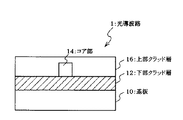
図1は、本発明の感光性組成物からなるクラッド層を含む光導波路の一例を模式的に示す断面図である。
図1中、光導波路1は、シリコンウエハの如き基板10と、下部クラッド層12と、上部クラッド層16と、これらのクラッド層12、16で保護されたコア部14とからなる。このうち、下部クラッド層12及び上部クラッド層16のいずれか一方又は両方は、本発明の感光性組成物を用いて形成される。
The manufacturing method of the optical waveguide of this invention is not specifically limited, A well-known method can be used. Specifically, the optical waveguide is manufactured as follows.
FIG. 1 is a cross-sectional view schematically showing an example of an optical waveguide including a clad layer made of the photosensitive composition of the present invention.
In FIG. 1, the optical waveguide 1 includes a substrate 10 such as a silicon wafer, a lower cladding layer 12, an upper cladding layer 16, and a core portion 14 protected by these cladding layers 12 and 16. Among these, any one or both of the lower clad layer 12 and the upper clad layer 16 are formed using the photosensitive composition of the present invention.
光導波路1を作製する方法の一例は、次のとおりである。
まず、基板10の表面にスピンコート法によって本発明の樹脂組成物を塗布し、紫外線を照射して硬化させ、下部クラッド層12を形成する。そして、下部クラッド層12の上にコア部形成用の他の感光性樹脂組成物を塗布し、上方から所定のラインパターンを有するフォトマスクを介して紫外線を照射する。これによって、紫外線が照射された箇所のみが硬化するので、それ以外の未硬化の部分を現像液によって除去し、コア部14を得る。
次いで、下部クラッド層12及びコア部14の上面に本発明の樹脂組成物を塗布し、紫外線を照射して硬化させ、上部クラッド層16を形成すれば、光導波路1が完成する。
An example of a method for producing the optical waveguide 1 is as follows.
First, the resin composition of the present invention is applied to the surface of the substrate 10 by spin coating, and cured by irradiating with ultraviolet rays to form the lower cladding layer 12. And the other photosensitive resin composition for core part formation is apply | coated on the lower clad layer 12, and an ultraviolet-ray is irradiated through the photomask which has a predetermined line pattern from upper direction. As a result, only the portion irradiated with the ultraviolet light is cured, and the other uncured portion is removed by the developer to obtain the core portion 14.
Next, the optical waveguide 1 is completed when the resin composition of the present invention is applied to the upper surfaces of the lower cladding layer 12 and the core portion 14 and cured by irradiating with ultraviolet rays to form the upper cladding layer 16.
本発明の光導波路の製造においては、基板を用いることが好ましいが、基板の材料(基材)については、特に制限されず、公知のものから適宜選択すればよい。具体的には、シリコンウエハ、ガラス板、ポリイミド基板、ガラエポ基板等が挙げられ、シリコンウエハやガラエポ基板等が好ましい。 In the production of the optical waveguide of the present invention, it is preferable to use a substrate, but the material (base material) of the substrate is not particularly limited and may be appropriately selected from known ones. Specifically, a silicon wafer, a glass plate, a polyimide substrate, a glass epoxy substrate, etc. are mentioned, and a silicon wafer, a glass epoxy substrate, etc. are preferable.
本発明の光導波路の構造は、特に限定されず、公知の如何なる構造を有していてもよい。代表的な構造としては、例えば、図1に記載のものが挙げられる。 The structure of the optical waveguide of the present invention is not particularly limited, and may have any known structure. As a typical structure, for example, the structure shown in FIG.
本発明の光導波路は、優れた光伝送特性を有し、導波路に要求される信頼性特性に優れている。 The optical waveguide of the present invention has excellent optical transmission characteristics and excellent reliability characteristics required for the waveguide.
以下、実施例を挙げて本発明をさらに具体的に説明するが、本発明は、これらの実施例に限定されるものではない。また、以下の説明において「部」及び「%」は、特にことわらない限り、それぞれ質量部及び質量%を示す。 EXAMPLES Hereinafter, although an Example is given and this invention is demonstrated further more concretely, this invention is not limited to these Examples. In the following description, “parts” and “%” represent parts by mass and mass%, respectively, unless otherwise specified.
(光導波路形成用感光性樹脂組成物の調製)
実施例1
下記表1に記載の各成分をフラスコに添加し、60℃にて均一透明液体になるまで攪拌し、液状の樹脂組成物(樹脂1)を得た。
(Preparation of photosensitive resin composition for optical waveguide formation)
Example 1
Each component described in Table 1 below was added to a flask and stirred at 60 ° C. until a uniform transparent liquid was obtained, to obtain a liquid resin composition (Resin 1).
実施例2、3及び比較例1、2
添加する成分の種類と割合を、下記表1に記載のとおりに変えた以外は実施例1と同様にして液状の樹脂組成物(樹脂2〜5)を得た。
Examples 2 and 3 and Comparative Examples 1 and 2
Liquid resin compositions (resins 2 to 5) were obtained in the same manner as in Example 1 except that the types and ratios of the components to be added were changed as shown in Table 1 below.
<屈折率の測定方法>
実施例1〜3及び比較例1、2で得られた液状の樹脂組成物(樹脂1〜5)を硬化させた硬化膜について、824nmでの屈折率を以下の手法により測定した。まず、スピンコーターを用いて、回転数及び時間を調整しながら、4インチのシリコンウエファ基板上に実施例1〜3、比較例1、2で得た各液状の樹脂組成物(樹脂1〜5)を7μm厚になるように塗布して樹脂組成物層を形成させた後、窒素雰囲気下、1.0J/cm2の紫外線をマスクアライナーから樹脂組成物層に照射し、硬化膜を得た。次いで、日本メトリコン製プリズムカップラーを用いて、この硬化膜の屈折率(824nm、25℃)を測定した。
<Measurement method of refractive index>
About the cured film which hardened | cured the liquid resin composition (resin 1-5) obtained in Examples 1-3 and Comparative Examples 1 and 2, the refractive index in 824 nm was measured with the following method. First, the liquid resin compositions (resins 1 to 5) obtained in Examples 1 to 3 and Comparative Examples 1 and 2 were formed on a 4-inch silicon wafer substrate while adjusting the rotation speed and time using a spin coater. ) To a thickness of 7 μm to form a resin composition layer, and then irradiated with 1.0 J / cm 2 of UV light from the mask aligner to the resin composition layer in a nitrogen atmosphere to obtain a cured film. . Next, the refractive index (824 nm, 25 ° C.) of this cured film was measured using a prism coupler made by Nippon Metricon.
<塗工性の評価方法>
スピンコーターを用いて回転数および時間を調整しながら、4インチのシリコンウエハ基板上に樹脂組成物を50μm厚になるように塗布して樹脂組成物層を形成させた後、温度25℃、相対湿度25%で10分放置した。放置後、塗膜表面に「はじき」や「むら」がみられた場合を「×」、「はじき」や「むら」が観察されなかった場合を「○」とした。
<Evaluation method of coatability>
A resin composition layer was formed by applying a resin composition to a thickness of 50 μm on a 4-inch silicon wafer substrate while adjusting the number of rotations and time using a spin coater. It was left for 10 minutes at a humidity of 25%. After leaving, “x” indicates that “repelling” or “unevenness” was observed on the surface of the coating film, and “◯” indicates that no “repelling” or “unevenness” was observed.
表1中の略号は以下のものを示す。
CC−15:前記式(2)において、n=15の化合物(旭電化工業製、第4級ポリエーテルアンモニウム塩;アデカコールCC−15)
CC−42:前記式(2)において、n=40の化合物(旭電化工業製、第4級ポリエーテルアンモニウム塩;アデカコールCC−42)
AA−6:メタクリロイル基含有ポリメタクリル酸メチル(PMMA)(東亞合成製;マクロマーAA−6)
V779:テトラブロモビスフェノールA型エポキシジアクリレート(日本ユピカ製;ネオポールV779)
TCDDA:トリシクロデカンジメタノールジアクリレート(三菱化学製;SA1002)
BR−31:トリブロモフェノキシエチルアクリレート(第一工業製薬製;ニューフロンティアBR−31)
VP:N−ビニルピロリドン(BASF製;VP)
NDDA:1,9−ノナンジオールジアクリレート(第一工業製薬製;LC9A)
IBXMA:イソボルニルメタクリレート(大阪有機化学製;IB−X)
Irg.184:シクロヘキシルアセトフェノン(チバスペシャリティケミカルズ製;Irgacure 184)
A203F:ポリオキシアルキレンアルキルエーテルリン酸エステル(第一工業製薬製;プライサーフ A203F)
264−WAX:変性脂肪族ジメチルエチルアンモニウムエトサルフェート(日本油脂製;エレガン 264−WAX)
The abbreviations in Table 1 indicate the following.
CC-15: Compound of the above formula (2), n = 15 (manufactured by Asahi Denka Kogyo Co., Ltd., quaternary polyether ammonium salt; Adekacol CC-15)
CC-42: In the above formula (2), n = 40 compound (Asahi Denka Kogyo Co., Ltd., quaternary polyether ammonium salt; Adekacol CC-42)
AA-6: Polymethyl methacrylate (PMMA) containing methacryloyl group (manufactured by Toagosei; Macromer AA-6)
V779: Tetrabromobisphenol A type epoxy diacrylate (manufactured by Nippon Iupika; Neopol V779)
TCDDA: Tricyclodecane dimethanol diacrylate (Mitsubishi Chemical; SA1002)
BR-31: Tribromophenoxyethyl acrylate (Daiichi Kogyo Seiyaku; New Frontier BR-31)
VP: N-vinylpyrrolidone (manufactured by BASF; VP)
NDDA: 1,9-nonanediol diacrylate (Daiichi Kogyo Seiyaku; LC9A)
IBXMA: Isobornyl methacrylate (manufactured by Osaka Organic Chemicals; IB-X)
Irg. 184: Cyclohexyl acetophenone (manufactured by Ciba Specialty Chemicals; Irgacure 184)
A203F: Polyoxyalkylene alkyl ether phosphate ester (Daiichi Kogyo Seiyaku; Prisurf A203F)
264-WAX: modified aliphatic dimethylethylammonium ethosulphate (manufactured by NOF; Elegan 264-WAX)
表1の結果から、式(1)で示される化合物以外の添加剤(界面活性剤)を添加した比較例1、2の樹脂組成物では、基板、特にシリコンウエファに対する塗工性が悪いのに対し、前記式(1)で示される化合物を添加した実施例1〜3の樹脂組成物では、塗工性が良好であり、式(1)で示される化合物の添加により、基板への塗工性が改善されることがわかる。 From the results shown in Table 1, the resin compositions of Comparative Examples 1 and 2 to which an additive (surfactant) other than the compound represented by the formula (1) is added have poor coatability on a substrate, particularly a silicon wafer. On the other hand, in the resin compositions of Examples 1 to 3 to which the compound represented by the formula (1) was added, the coating property was good, and the application to the substrate was achieved by the addition of the compound represented by the formula (1). It can be seen that the performance is improved.
(光導波路の作製)
実施例4〜6、比較例3、4
スピンコーターを用いて、回転数及び時間を調整しながら、4インチのシリコンウエファ基板の上に、実施例2で調製した樹脂2を50μm厚になるように塗布した後、当該塗布層(下部クラッド層)に、空気雰囲気下、1.0J/cm2の紫外線をマスクアライナーから照射した。次いで、スピンコーターを用いて、下部クラッド層の上に、実施例1で調製した樹脂1を、50μm厚になるように塗布した後、空気雰囲気下、1.0J/cm2の紫外線を、50μm幅の分岐のない直線形状を有するフォトマスクを介して当該塗布層に照射した。アセトンを用いて、照射後の塗布層を3分間現像処理した後、70℃に設定したオーブン中で基板を10分間加温し、コア部を形成した。さらに、この上に、樹脂2を再度、50μm厚になるように再び塗布した後、紫外線を基板に照射して上部クラッド層とし、チャネル導波路を得た。
(Production of optical waveguide)
Examples 4 to 6, Comparative Examples 3 and 4
Using a spin coater, the resin 2 prepared in Example 2 was applied to a thickness of 50 μm on a 4-inch silicon wafer substrate while adjusting the number of revolutions and time. Layer) was irradiated with 1.0 J / cm 2 of ultraviolet light from a mask aligner under an air atmosphere. Next, after applying the resin 1 prepared in Example 1 to a thickness of 50 μm on the lower clad layer using a spin coater, 1.0 J / cm 2 of ultraviolet light in an air atmosphere was applied to 50 μm. The coating layer was irradiated through a photomask having a linear shape with no branching in width. The coated layer after irradiation was developed with acetone for 3 minutes, and then the substrate was heated in an oven set at 70 ° C. for 10 minutes to form a core part. Further, the resin 2 was again applied thereon so as to have a thickness of 50 μm, and then the substrate was irradiated with ultraviolet rays to form an upper clad layer, thereby obtaining a channel waveguide.
実施例4〜6及び比較例3、4
クラッド層(下部クラッド層)及びコア部を形成する樹脂組成物を、それぞれ表2に示す樹脂組成物に変えた以外は実施例4と同様にしてチャネル導波路を作製した。
Examples 4 to 6 and Comparative Examples 3 and 4
A channel waveguide was produced in the same manner as in Example 4 except that the resin composition forming the clad layer (lower clad layer) and the core part was changed to the resin composition shown in Table 2, respectively.
実施例4〜6及び比較例3、4で得られたチャネル導波路の伝送損失、長期信頼性を評価した。結果を下記表2に示す。
<伝送損失の評価>
導波路の端面をへき開にてカットした後、マルチモードファイバ(50μm径)を介して850nmの光を挿入し、カットバック法により導波路損失を測定した。カットバックは、導波路長5cmから1cm刻みに4点測定して行なった。得られた光強度を導波路長に関してプロットし、その傾きから損失値を算出した。得られた損失値が1.0dB/cm以下であるときを「○」、それよりも高いときを「×」として評価した。
The transmission loss and long-term reliability of the channel waveguides obtained in Examples 4 to 6 and Comparative Examples 3 and 4 were evaluated. The results are shown in Table 2 below.
<Evaluation of transmission loss>
After the end face of the waveguide was cut by cleavage, 850 nm light was inserted through a multimode fiber (50 μm diameter), and the waveguide loss was measured by the cutback method. Cutback was performed by measuring four points in steps of 1 cm from a waveguide length of 5 cm. The obtained light intensity was plotted with respect to the waveguide length, and the loss value was calculated from the slope. When the obtained loss value was 1.0 dB / cm or less, “◯” was evaluated, and when the loss value was higher than that, “X” was evaluated.
<長期信頼性の評価>
1.高温高湿試験
作製した光導波路を3cm長に切断し、850nmの光を挿入し初期挿入損失を測定後、温度85℃、相対湿度85%の恒温槽内で1000時間放置した。その後、導波路を取り出し、温度25℃、相対湿度50%で24時間の状態調整を行った後、再度、挿入損失を測定した。初期挿入損失と比較し、その変化量が1dBを超えるものを「×」、1dB以内のものを「○」とした。
<Evaluation of long-term reliability>
1. High-temperature and high-humidity test The produced optical waveguide was cut to a length of 3 cm, 850 nm light was inserted and the initial insertion loss was measured, and then left in a constant temperature bath at a temperature of 85 ° C. and a relative humidity of 85% for 1000 hours. Thereafter, the waveguide was taken out and adjusted for 24 hours at a temperature of 25 ° C. and a relative humidity of 50%, and then the insertion loss was measured again. Compared with the initial insertion loss, the case where the amount of change exceeds 1 dB is indicated as “X”, and the case where the change is within 1 dB is indicated as “◯”.
2.ヒートサイクル試験
作製した光導波路を3cm長に切断し、850nmの光を挿入し初期挿入損失を測定後、−40℃と85℃での30分間隔での保存を短時間で繰り返すヒートサイクル試験を実施した。100サイクルの試験後、導波路を取り出し、温度25℃、相対湿度50%で24時間の状態調整を行った後、再度、挿入損失を測定した。初期挿入損失と比較し、その変化量が1dBを超えるものを「×」、1dB以内のものを「○」とした。
2. Heat cycle test Cut the manufactured optical waveguide into 3cm length, insert light at 850nm, measure the initial insertion loss, and then repeat the heat cycle test at -40 ° C and 85 ° C at 30 minute intervals in a short time. Carried out. After 100 cycles of the test, the waveguide was taken out, adjusted for 24 hours at a temperature of 25 ° C. and a relative humidity of 50%, and then the insertion loss was measured again. Compared with the initial insertion loss, the case where the amount of change exceeds 1 dB is indicated as “X”, and the case where the change is within 1 dB is indicated as “◯”.
表2中の略号は以下のものを示す。
PJ3001:感光性アクリル樹脂(JSR製;オプスターPJ3001)
The abbreviations in Table 2 indicate the following.
PJ3001: photosensitive acrylic resin (manufactured by JSR; Opstar PJ3001)
表2の結果から、少なくとも下部クラッド層が本発明の樹脂組成物からなる光導波路は、伝送損失が小さく、また、長期信頼性も高いことが明らかとなった。 From the results in Table 2, it is clear that the optical waveguide having at least the lower cladding layer made of the resin composition of the present invention has a small transmission loss and a high long-term reliability.
本発明によれば、前処理を施さなくても、はじきが抑制され、均一な塗膜が得られる光導波路形成用感光性樹脂組成物を提供できる。そのため、安価に大面積での導波路作製が可能になり、工業上、非常に有用である。
また、本発明の樹脂組成物を用いれば、基板との密着性が良好な塗膜が形成でき、基板からの剥離等もみられず長期信頼性の高い光導波路を作製できる。
According to the present invention, it is possible to provide a photosensitive resin composition for forming an optical waveguide in which repelling is suppressed and a uniform coating film can be obtained without performing pretreatment. Therefore, it is possible to produce a waveguide with a large area at low cost, which is very useful industrially.
Moreover, if the resin composition of this invention is used, the coating film with favorable adhesiveness with a board | substrate can be formed, and the optical waveguide with high long-term reliability can be produced, without peeling from a board | substrate etc. being seen.
1 光導波路
10 基板
12 下部クラッド層
14 コア部
16 上部クラッド層
DESCRIPTION OF SYMBOLS 1 Optical waveguide 10 Substrate 12 Lower clad layer 14 Core part 16 Upper clad layer
Claims (3)
で示される化合物、
重合性化合物、及び
光重合開始剤
を含有する光導波路形成用感光性樹脂組成物。 Following formula (1)
A compound represented by
The photosensitive resin composition for optical waveguide formation containing a polymeric compound and a photoinitiator.
An optical waveguide having a core layer and a clad layer, wherein either or both of the core layer and the clad layer are made of the photosensitive resin composition for forming an optical waveguide according to claim 1 or 2. .
Priority Applications (1)
| Application Number | Priority Date | Filing Date | Title |
|---|---|---|---|
| JP2004104549A JP4360252B2 (en) | 2004-03-31 | 2004-03-31 | Photosensitive resin composition for optical waveguide formation, and optical waveguide formed using the same |
Applications Claiming Priority (1)
| Application Number | Priority Date | Filing Date | Title |
|---|---|---|---|
| JP2004104549A JP4360252B2 (en) | 2004-03-31 | 2004-03-31 | Photosensitive resin composition for optical waveguide formation, and optical waveguide formed using the same |
Publications (2)
| Publication Number | Publication Date |
|---|---|
| JP2005290106A true JP2005290106A (en) | 2005-10-20 |
| JP4360252B2 JP4360252B2 (en) | 2009-11-11 |
Family
ID=35323415
Family Applications (1)
| Application Number | Title | Priority Date | Filing Date |
|---|---|---|---|
| JP2004104549A Expired - Fee Related JP4360252B2 (en) | 2004-03-31 | 2004-03-31 | Photosensitive resin composition for optical waveguide formation, and optical waveguide formed using the same |
Country Status (1)
| Country | Link |
|---|---|
| JP (1) | JP4360252B2 (en) |
Cited By (4)
| Publication number | Priority date | Publication date | Assignee | Title |
|---|---|---|---|---|
| CN102455464A (en) * | 2010-10-27 | 2012-05-16 | 日东电工株式会社 | Optical waveguide production method |
| US8771562B2 (en) | 2010-06-02 | 2014-07-08 | Nitto Denko Corporation | Optical waveguide production method |
| US8778451B2 (en) | 2010-07-05 | 2014-07-15 | Nitto Denko Corporation | Method of manufacturing optical waveguide |
| US8778452B2 (en) | 2010-07-05 | 2014-07-15 | Nitto Denko Corporation | Method of manufacturing optical waveguide |
-
2004
- 2004-03-31 JP JP2004104549A patent/JP4360252B2/en not_active Expired - Fee Related
Cited By (6)
| Publication number | Priority date | Publication date | Assignee | Title |
|---|---|---|---|---|
| US8771562B2 (en) | 2010-06-02 | 2014-07-08 | Nitto Denko Corporation | Optical waveguide production method |
| US8778451B2 (en) | 2010-07-05 | 2014-07-15 | Nitto Denko Corporation | Method of manufacturing optical waveguide |
| US8778452B2 (en) | 2010-07-05 | 2014-07-15 | Nitto Denko Corporation | Method of manufacturing optical waveguide |
| CN102455464A (en) * | 2010-10-27 | 2012-05-16 | 日东电工株式会社 | Optical waveguide production method |
| JP2012093564A (en) * | 2010-10-27 | 2012-05-17 | Nitto Denko Corp | Method of manufacturing optical waveguide |
| US8652569B2 (en) | 2010-10-27 | 2014-02-18 | Nitto Denko Corporation | Optical waveguide production method |
Also Published As
| Publication number | Publication date |
|---|---|
| JP4360252B2 (en) | 2009-11-11 |
Similar Documents
| Publication | Publication Date | Title |
|---|---|---|
| JP3746871B2 (en) | Liquid curable resin composition | |
| JP6106253B1 (en) | OPTICAL FIBER TAPE, OPTICAL FIBER TAPE MANUFACTURING METHOD, AND ULTRAVIOLET-CURABLE RESIN COMPOSITION USED FOR FORMING INTERCONNECTION OF INTERNAL FIXED OPTICAL FIBER TAPE | |
| JPH09278850A (en) | Liquid curable resin composition | |
| JPH10231341A (en) | Liquid curable resin composition | |
| JP2004131520A (en) | Photocurable resin composition and optical member | |
| JP2000026562A (en) | Liquid curable resin composition | |
| JP4222120B2 (en) | Photosensitive resin composition for optical waveguide formation and optical waveguide | |
| JP2003277453A (en) | Liquid curable resin composition | |
| JP2006058831A (en) | Photosensitive resin composition for optical waveguide and optical waveguide | |
| JP4385818B2 (en) | Photosensitive resin composition and optical waveguide | |
| JP4360252B2 (en) | Photosensitive resin composition for optical waveguide formation, and optical waveguide formed using the same | |
| JP4789329B2 (en) | Double layer film | |
| JP4840586B2 (en) | Photosensitive resin composition for optical waveguide, optical waveguide and method for producing the same | |
| JPWO2007125740A1 (en) | Dry film for forming optical waveguide, optical waveguide and method for producing the same | |
| JP2000239333A (en) | Photocurable resin composition and optical member | |
| CN1498234A (en) | Liquid curable resin composition and cured product | |
| JP4151508B2 (en) | Photosensitive resin composition for optical waveguide and optical waveguide | |
| JP2008116971A (en) | Optical waveguide | |
| JP2005258000A (en) | Photosensitive composition for forming optical waveguide and optical waveguide | |
| JP5115057B2 (en) | Film-shaped optical waveguide and photosensitive resin composition for film-shaped optical waveguide | |
| JP2000109528A (en) | Liquid curable resin composition | |
| JP4594775B2 (en) | Liquid curable resin composition | |
| JP4766215B2 (en) | Curable resin composition for optical fiber tape material | |
| JP2007297467A (en) | Liquid curable resin composition | |
| JP2006348198A (en) | Photocurable resin composition and prism lens sheet |
Legal Events
| Date | Code | Title | Description |
|---|---|---|---|
| A621 | Written request for application examination |
Free format text: JAPANESE INTERMEDIATE CODE: A621 Effective date: 20060727 |
|
| A977 | Report on retrieval |
Free format text: JAPANESE INTERMEDIATE CODE: A971007 Effective date: 20081222 |
|
| TRDD | Decision of grant or rejection written | ||
| A01 | Written decision to grant a patent or to grant a registration (utility model) |
Free format text: JAPANESE INTERMEDIATE CODE: A01 Effective date: 20090721 |
|
| A01 | Written decision to grant a patent or to grant a registration (utility model) |
Free format text: JAPANESE INTERMEDIATE CODE: A01 |
|
| A61 | First payment of annual fees (during grant procedure) |
Free format text: JAPANESE INTERMEDIATE CODE: A61 Effective date: 20090803 |
|
| R150 | Certificate of patent or registration of utility model |
Free format text: JAPANESE INTERMEDIATE CODE: R150 |
|
| FPAY | Renewal fee payment (event date is renewal date of database) |
Free format text: PAYMENT UNTIL: 20120821 Year of fee payment: 3 |
|
| FPAY | Renewal fee payment (event date is renewal date of database) |
Free format text: PAYMENT UNTIL: 20120821 Year of fee payment: 3 |
|
| FPAY | Renewal fee payment (event date is renewal date of database) |
Free format text: PAYMENT UNTIL: 20120821 Year of fee payment: 3 |
|
| FPAY | Renewal fee payment (event date is renewal date of database) |
Free format text: PAYMENT UNTIL: 20130821 Year of fee payment: 4 |
|
| R250 | Receipt of annual fees |
Free format text: JAPANESE INTERMEDIATE CODE: R250 |
|
| R250 | Receipt of annual fees |
Free format text: JAPANESE INTERMEDIATE CODE: R250 |
|
| R250 | Receipt of annual fees |
Free format text: JAPANESE INTERMEDIATE CODE: R250 |
|
| R250 | Receipt of annual fees |
Free format text: JAPANESE INTERMEDIATE CODE: R250 |
|
| R250 | Receipt of annual fees |
Free format text: JAPANESE INTERMEDIATE CODE: R250 |
|
| LAPS | Cancellation because of no payment of annual fees |