JP2005289298A - Electric power steering device - Google Patents
Electric power steering device Download PDFInfo
- Publication number
- JP2005289298A JP2005289298A JP2004110627A JP2004110627A JP2005289298A JP 2005289298 A JP2005289298 A JP 2005289298A JP 2004110627 A JP2004110627 A JP 2004110627A JP 2004110627 A JP2004110627 A JP 2004110627A JP 2005289298 A JP2005289298 A JP 2005289298A
- Authority
- JP
- Japan
- Prior art keywords
- inner ring
- ball
- pinion shaft
- outer ring
- balls
- Prior art date
- Legal status (The legal status is an assumption and is not a legal conclusion. Google has not performed a legal analysis and makes no representation as to the accuracy of the status listed.)
- Pending
Links
Images


Classifications
-
- F—MECHANICAL ENGINEERING; LIGHTING; HEATING; WEAPONS; BLASTING
- F16—ENGINEERING ELEMENTS AND UNITS; GENERAL MEASURES FOR PRODUCING AND MAINTAINING EFFECTIVE FUNCTIONING OF MACHINES OR INSTALLATIONS; THERMAL INSULATION IN GENERAL
- F16C—SHAFTS; FLEXIBLE SHAFTS; ELEMENTS OR CRANKSHAFT MECHANISMS; ROTARY BODIES OTHER THAN GEARING ELEMENTS; BEARINGS
- F16C19/00—Bearings with rolling contact, for exclusively rotary movement
- F16C19/02—Bearings with rolling contact, for exclusively rotary movement with bearing balls essentially of the same size in one or more circular rows
- F16C19/14—Bearings with rolling contact, for exclusively rotary movement with bearing balls essentially of the same size in one or more circular rows for both radial and axial load
- F16C19/16—Bearings with rolling contact, for exclusively rotary movement with bearing balls essentially of the same size in one or more circular rows for both radial and axial load with a single row of balls
- F16C19/163—Bearings with rolling contact, for exclusively rotary movement with bearing balls essentially of the same size in one or more circular rows for both radial and axial load with a single row of balls with angular contact
- F16C19/166—Four-point-contact ball bearings
-
- F—MECHANICAL ENGINEERING; LIGHTING; HEATING; WEAPONS; BLASTING
- F16—ENGINEERING ELEMENTS AND UNITS; GENERAL MEASURES FOR PRODUCING AND MAINTAINING EFFECTIVE FUNCTIONING OF MACHINES OR INSTALLATIONS; THERMAL INSULATION IN GENERAL
- F16C—SHAFTS; FLEXIBLE SHAFTS; ELEMENTS OR CRANKSHAFT MECHANISMS; ROTARY BODIES OTHER THAN GEARING ELEMENTS; BEARINGS
- F16C2240/00—Specified values or numerical ranges of parameters; Relations between them
- F16C2240/40—Linear dimensions, e.g. length, radius, thickness, gap
- F16C2240/70—Diameters; Radii
- F16C2240/76—Osculation, i.e. relation between radii of balls and raceway groove
-
- F—MECHANICAL ENGINEERING; LIGHTING; HEATING; WEAPONS; BLASTING
- F16—ENGINEERING ELEMENTS AND UNITS; GENERAL MEASURES FOR PRODUCING AND MAINTAINING EFFECTIVE FUNCTIONING OF MACHINES OR INSTALLATIONS; THERMAL INSULATION IN GENERAL
- F16C—SHAFTS; FLEXIBLE SHAFTS; ELEMENTS OR CRANKSHAFT MECHANISMS; ROTARY BODIES OTHER THAN GEARING ELEMENTS; BEARINGS
- F16C2361/00—Apparatus or articles in engineering in general
- F16C2361/61—Toothed gear systems, e.g. support of pinion shafts
Landscapes
- Engineering & Computer Science (AREA)
- General Engineering & Computer Science (AREA)
- Mechanical Engineering (AREA)
- Rolling Contact Bearings (AREA)
- Power Steering Mechanism (AREA)
Abstract
Description
この発明に係る電動式パワーステアリング装置は、自動車の操舵装置に組み込み、電動モータの出力を補助動力として利用する事により、運転者がステアリングホイールを操作する為に要する力の軽減を図るものである。 The electric power steering device according to the present invention is incorporated in a steering device of an automobile and uses the output of an electric motor as auxiliary power to reduce the force required for the driver to operate the steering wheel. .
操舵輪(フォークリフト等の特殊車両を除き、通常は前輪)に舵角を付与する際に運転者がステアリングホイールを操作する為に要する力の軽減を図る為の装置として、パワーステアリング装置が広く使用されている。又、この様なパワーステアリング装置で、補助動力源として電動モータを使用する電動式パワーステアリング装置も、近年、軽乗用車や小型乗用車を中心に普及し始めている。電動式パワーステアリング装置は、油圧式のパワーステアリング装置に比べて小型・軽量にでき、補助動力の大きさ(トルク)の制御が容易で、しかもエンジンの動力損失が少ない等の利点がある。この為、今後は、より大型の乗用車に電動式パワーステアリング装置が適用されていく傾向にある。図6は、この様な電動式パワーステアリング装置のうちの、コラムアシスト式と呼ばれる電動パワーステアリング装置を組み込んだ操舵装置を示している。 A power steering device is widely used as a device to reduce the force required for the driver to operate the steering wheel when giving a steering angle to the steered wheels (usually the front wheels except for special vehicles such as forklifts) Has been. In addition, an electric power steering device that uses an electric motor as an auxiliary power source in such a power steering device has recently started to spread mainly in light passenger cars and small passenger cars. The electric power steering device can be made smaller and lighter than the hydraulic power steering device, has advantages such as easy control of the magnitude (torque) of auxiliary power and less power loss of the engine. For this reason, electric power steering devices tend to be applied to larger passenger cars in the future. FIG. 6 shows a steering apparatus in which an electric power steering apparatus called a column assist type is incorporated among such electric power steering apparatuses.
この操舵装置では、ステアリングホイール1の動きを、ステアリングシャフト2、自在継手3a、中間軸4、自在継手3bを介して、ステアリングギヤ5を構成するピニオン軸6に伝達する様にしている。このピニオン軸6は、ハウジング7内に回転自在に支持されており、回転に伴ってラック9(本発明の実施例を説明する為の後述する図1参照)を軸方向に変位させ、このラック9に連結したタイロッド13を介して、操舵輪に舵角を付与する。この為に、このラック9はその中間部を上記ハウジング7に、軸方向の変位自在に支持している。又、上記ピニオン軸6は、このラック9に対し捩れの位置関係で配置している。そして、このピニオン軸6の下端部外周面に形成したピニオン8(本発明の実施例を説明する為の後述する図1参照)を、このラック9と噛合させている。
In this steering apparatus, the movement of the
一方、上記ステアリングシャフト2を内側に挿通するステアリングコラム10の下端にはギヤハウジング11を結合しており、このギヤハウジング11に電動モータ12を支持している。そして、この電動モータ12により、上記ステアリングシャフト2に回転方向の補助力を付与する様にしている。
On the other hand, a
上記電動モータ12によりこの補助力を付与する為に、上記ステアリングシャフト2の中間部には、このステアリングホイール1からこのステアリングシャフト2に加えられるトルクの方向と大きさとを検出する図示しないトルクセンサを設けている。又、上記ステアリングシャフト2の中間部に図示しない減速機の出力側を結合し、上記電動モータ12の回転軸にこの減速機の入力側を結合している。この減速機として従来から、大きなリード角を有し、動力の伝達方向に関して可逆性を有するウォーム減速装置を、一般的に使用している。即ち、回転力受取部材であるウォームホイールを上記ステアリングシャフト2の中間部に固定すると共に、回転力付与部材であり上記電動モータ12の回転軸に結合固定したウォーム軸のウォームを、上記ウォームホイールと噛合させている。又、上記トルクセンサの検出信号は、車速を表す信号と共に、上記電動モータ12への通電を制御する為の制御器に入力している。
In order to apply this auxiliary force by the
操舵輪に舵角を付与する為、上記ステアリングホイール1を操作し、上記ステアリングシャフト2が回転すると、上記トルクセンサがこのステアリングシャフト2の回転方向とトルクとを検出し、その検出値を表す信号を上記制御器に送る。するとこの制御器は、上記電動モータ12に通電して、上記減速機を介して上記ステアリングシャフト2を、上記ステアリングホイール1に基づく回転方向と同方向に回転させる。この結果、上記ステアリングシャフト2の先端部(図6の下端部)は、上記ステアリングホイール1から付与された力に基づくトルクよりも大きなトルクで回転する。
When the
この様なステアリングシャフト2の先端部の回転は、前記自在継手3a、3b及び中間軸4を介して前記ステアリングギヤ5のピニオン軸6に伝達される。そして、このピニオン軸6が前記ピニオン8を回転させ、前記ラック9を介してタイロッド13を押し引きし、操舵輪に所望の舵角を付与する。上述した説明から明らかな通り、上記ステアリングシャフト2の先端部から自在継手3aを介して中間シャフト4に伝達されるトルクは、上記ステアリングホイール1から上記ステアリングシャフト2の基端部(図6の上端部)に加えられるトルクよりも、上記電動モータ12から減速機を介して加えられる補助力分だけ大きい。従って、上記操舵輪に舵角を付与する為に運転者が上記ステアリングホイール1を操作する為に要する力は、上記補助力分だけ小さくて済む様になる。
Such rotation of the tip of the
一方、上述の図6に示したコラムアシスト式の電動式パワーステアリング装置以外にも、ピニオンアシスト式、デュアルピニオン式、ラックアシスト式と呼ばれる電動式パワーステアリング装置も、従来から一部で使用されている。このうちのピニオンアシスト式の構造は、図7に示す様に、下端部にピニオン軸を結合した入力軸14を、その内側に挿通したギヤハウジング15の側方に、電動モータ12を支持している。そして、この電動モータ12により図示しない減速機を介して、上記ピニオン軸に回転方向の補助力を付与する様にしている。そして、上述の図6に示した構造と同様に、このピニオン軸の下端部外周面に設けたピニオンを、ラック9と噛合させている。
On the other hand, in addition to the column assist type electric power steering device shown in FIG. 6 described above, electric power steering devices called pinion assist type, dual pinion type, and rack assist type have also been used in part in the past. Yes. As shown in FIG. 7, the pinion assist type structure includes an
又、上記デュアルピニオン式の構造は、図8に示す様に、ラック9の一部でピニオン軸6の外周面に設けたピニオンから外れた部分に、第二のピニオン軸16を配置している。そして、この第二のピニオン軸16の一端部外周面に設けた第二のピニオンを、上記ラック9と噛合させている。又、この第二のピニオン軸16を内側に設けたハウジング17の側方に、電動モータ12を支持している。そして、この電動モータ12により、減速機18を介して、第二のピニオン軸16に回転方向の補助力を付与する様にしている。従って、上記ラック9は、この補助力に基づく力と、運転者がステアリングホイール1に付与する力に基づきピニオン軸6から加わる力とにより、軸方向に変位する。
Further, in the dual pinion type structure, as shown in FIG. 8, the
又、図示は省略するが、上記ラックアシスト式の構造は、ラックを内側に設けたハウジングの側方に電動モータを支持しており、この電動モータの回転を、減速機と、ボールねじ機構とを介して、上記ラックの軸方向の補助力に変換する様にしている。このラックは、この補助力と、運転者がステアリングホイールに付与する力に基づきピニオン軸から加わる力とにより、軸方向に変位する。 Although not shown, the rack-assist type structure supports an electric motor on the side of a housing provided with a rack inside, and the rotation of the electric motor is reduced by a reduction gear, a ball screw mechanism, and the like. It is made to convert into the auxiliary force of the said rack axial direction via. The rack is displaced in the axial direction by the auxiliary force and the force applied from the pinion shaft based on the force applied by the driver to the steering wheel.
この様な複数の形式の電動式パワーステアリング装置のうち、上述の図6〜7に示したコラムアシスト式とピニオンアシスト式との構造は、運転者による操舵力と電動モータ12による補助力とを合わせた力により、ピニオン軸6が回転する。この為、このピニオン軸6に加わる回転トルク(入力トルク)は、前述した油圧式のパワーステアリング装置のピニオン軸に加わる回転トルクの場合と比べてかなり大きくなる。例えば、運転者による操舵力と電動モータ12による補助力との比は、1:5〜1:6程度にする場合が多い。この為、上述のコラムアシスト式とピニオンアシスト式との電動式パワーステアリング装置では、ピニオン軸6に、上述の油圧式のパワーステアリング装置の場合に加わるトルクに比べて6〜7倍程度大きなトルクが付与される。
Among such a plurality of types of electric power steering devices, the above-described column assist type and pinion assist type structures shown in FIGS. 6 to 7 provide the steering force by the driver and the auxiliary force by the
又、上述の図8に示したデュアルピニオン式の電動式パワーステアリング装置では、運転者による操舵力がピニオン軸6に、電動モータ12の補助力が、このピニオン軸6とは別の第二のピニオン軸16に、それぞれ付与される。この様なデュアルピニオン式の構造の場合、この第二のピニオン軸16に加わるトルクは、上述のコラムアシスト式又はピニオンアシスト式の構造でピニオン軸6に加わるトルクよりも小さくはなる。但し、上記第二のピニオン軸16には、電動モータ12によるトルクが付与される為、油圧式の構造でピニオン軸に付与されるトルクよりもかなり大きなトルクが付与される。
Further, in the dual pinion type electric power steering apparatus shown in FIG. 8 described above, the steering force by the driver is applied to the pinion shaft 6 and the auxiliary force of the
上述の様に、コラムアシスト式及びピニオンアシスト式の電動パワーステアリング装置を構成するピニオン軸6や、デュアルピニオン式の電動パワーステアリング装置を構成する第二のピニオン軸16には、大きな入力トルクが付与される。そして、この入力トルクが大きくなるのに従って、この入力トルクにほぼ比例した大きなギヤ反力が、ラック9から上記ピニオン軸6(図6、7の構造の場合)又は第二のピニオン軸16(図8の構造の場合)に加わる。この為、このピニオン軸6又は第二のピニオン軸16を、固定のハウジング7に回転自在に支持する軸受に加わる荷重が大きくなり、この軸受の負荷能力を高くする必要がある。これに対して、従来からこの軸受を玉軸受とする場合に、組み込む玉の数を多くする事で負荷能力を高くしているが、これら玉の数を多くする場合には、外輪の内周面で外輪軌道から両端側に外れた部分に設けた外径側肩部と、内輪の外周面で内輪軌道から両端側に外れた部分に設けた内径側肩部との高さを大きく(高く)する事ができなくなる。即ち、外輪及び内輪として、従来からそれぞれ単一の部材から成るものを使用している為、この外輪の内周面とこの内輪の外周面との間に玉を組み込む場合には、内輪を外輪に対し大きく偏心させた状態で、この間部分が大きくなった円周方向一部を通じて、これら内、外両輪の側方から内側に玉を組み込む必要がある。この為、上記各肩部の高さが大きいと、多くの玉を組み込む事ができない。従って、玉軸受の負荷能力を高くすべく多くの玉を組み込む為に、従来から、上記各肩部の高さを小さく(低く)している。
As described above, a large input torque is applied to the pinion shaft 6 constituting the column assist type and pinion assist type electric power steering device and the
但し、これら各肩部の高さを小さくすると、各玉の転動面と内輪軌道及び外輪軌道との転がり接触部がこれら各軌道の幅方向端縁部分に達する、所謂玉の乗り上げが生じ易くなる。この玉の乗り上げが生じた場合には、上記各玉の転動面と上記内輪、外輪各軌道とにエッジロードに基づく過大面圧が加わる(局部的に応力が集中する)為、これら転動面や各軌道に早期に圧痕等の損傷が生じて、軸受寿命が低下する原因となる。又、上述の様に、コラムアシスト式、ピニオンアシスト式、デュアルピニオン式の構造で、ピニオン軸6又は第二のピニオン軸16を支持する玉軸受に大きな荷重が加わる場合には、玉軸受に加わる大きなアキシアル方向の荷重により、上記玉の乗り上げがより一層生じ易くなる。
However, when the height of each shoulder portion is reduced, the rolling contact portion between the rolling surface of each ball and the inner ring raceway and the outer ring raceway reaches the edge in the width direction of each raceway, so-called ball riding is likely to occur. Become. When this ball rides on, an excessive surface pressure based on the edge load is applied to the rolling surfaces of the balls and the races of the inner ring and outer ring (stress is concentrated locally). Damage to the surface and each raceway, such as indentation, occurs early, causing a decrease in bearing life. As described above, when a large load is applied to the ball bearing supporting the pinion shaft 6 or the
一方、ピニオン軸6又は第二のピニオン軸16を支持する軸受に加わる荷重が大きくなると、この荷重にほぼ比例してこの軸受の軸受損失(摩擦損失)が大きくなる。そもそも、電動パワーステアリング装置を採用する目的の一つは、油圧式のパワーステアリング装置よりもエンジンの動力損失を少なくする点にある。この為、上記軸受損失を可能な限り小さく抑える事が好ましい。従って、上記ピニオン軸6又は第二のピニオン軸16を支持する軸受に加わる荷重が大きくなる、電動式パワーステアリング装置の場合でも、この軸受の軸受損失を小さく抑える事が望まれる。
尚、本発明に関連する先行技術文献として、特許文献1、2及び非特許文献1がある。
On the other hand, when the load applied to the bearing supporting the pinion shaft 6 or the
As prior art documents related to the present invention, there are
本発明の電動式パワーステアリング装置は、上述の様な事情に鑑みて、コラムアシスト式、ピニオンアシスト式、デュアルピニオン式等の、使用時にピニオン軸又は第二のピニオン軸に大きな入力トルクが付与される構造で、これらピニオン軸を支持する軸受として、負荷能力及び耐久性の向上と軸受損失の低減とに関して最適なものを採用する事により、負荷能力及び耐久性を十分に確保でき、且つ高効率な構造を実現すべく発明したものである。 In the electric power steering apparatus of the present invention, a large input torque is applied to the pinion shaft or the second pinion shaft during use, such as a column assist type, a pinion assist type, and a dual pinion type, in view of the above-described circumstances. By adopting the most suitable bearing for supporting these pinion shafts with regard to improving load capacity and durability and reducing bearing loss, the load capacity and durability can be sufficiently secured and high efficiency can be achieved. Invented to realize a simple structure.
本発明の電動式パワーステアリング装置は、前述した様な従来から知られている電動式パワーステアリング装置と同様に、軸方向に変位する事で操舵輪に舵角を付与するラックと、その一部外周面に設けたピニオンをこのラックと噛合させた状態で回転駆動自在とされたピニオン軸と、このピニオン軸又はこのピニオン軸よりもステアリングホイール側に連結した別の軸に回転方向の補助力を付与する電動モータとを備える。尚、この「ピニオン軸」は、デュアルピニオン式の構造を構成する第二のピニオン軸も含む(特許請求の範囲の記載に関しても同じとする。)。 The electric power steering apparatus according to the present invention includes a rack that imparts a steering angle to the steered wheels by being displaced in the axial direction, and a part of the rack, similar to the conventionally known electric power steering apparatus as described above. An auxiliary force in the rotational direction is applied to the pinion shaft that can be rotated and driven with the pinion provided on the outer peripheral surface engaged with the rack, and to another shaft connected to the steering wheel side of the pinion shaft or the pinion shaft. An electric motor to be applied. The “pinion shaft” includes a second pinion shaft constituting a dual pinion type structure (the same applies to the description of the claims).
特に、本発明の電動式パワーステアリング装置に於いては、上記ピニオン軸を固定の部分に支持する複数の軸受のうち、少なくとも何れかの軸受が、外周面に玉の転動面と2点で接触する形状の内輪軌道を有する内輪と、内周面に玉の転動面と2点で接触する形状の外輪軌道を有する外輪と、これら内輪軌道と外輪軌道との間に転動自在に設けられた複数個の玉とを備え、上記外輪軌道及び内輪軌道とこれら各玉の転動面とがそれぞれ2点ずつで接触する4点接触型であり、上記内輪又は外輪を、それぞれの軌道面が互いに対称の形状である1対の軌道輪素子を一体に重ね合わせる事により構成した玉軸受である。 In particular, in the electric power steering apparatus according to the present invention, at least one of the plurality of bearings that support the pinion shaft on the fixed portion has a ball rolling surface on the outer peripheral surface at two points. An inner ring having an inner ring raceway in contact with the inner ring, an outer ring having an outer ring raceway in contact with the ball rolling surface at two points on the inner circumferential surface, and a rollable portion provided between the inner ring raceway and the outer ring raceway. A four-point contact type in which the outer ring raceway and the inner ring raceway and the rolling surface of each ball are in contact with each other at two points, and the inner ring or outer ring is connected to each raceway surface. Is a ball bearing constructed by superimposing a pair of bearing ring elements having symmetrical shapes.
上述の様に構成する本発明の電動式パワーステアリング装置の場合には、ピニオン軸を支持する軸受のうちの少なくとも何れかの軸受を、内輪又は外輪を、それぞれの軌道面が互いに対称の形状である1対の軌道輪素子を一体に重ね合わせる事により構成した玉軸受としている。この為、この軸受として、内輪及び外輪をそれぞれ単一の部材により構成した玉軸受を使用する従来構造の場合と異なり、内輪の外周面と外輪の外周面との間に玉を組み込む場合に、内輪を外輪に対し大きく偏心させつつこの間部分が大きくなった円周方向一部を通じて、玉軸受の内側に玉を組み込む事を行なう必要がなくなる。即ち、本発明の場合には、玉軸受に玉を組み込む場合に、内輪と外輪とのうち、1対の軌道輪素子により構成する軌道輪の側から、これら両軌道輪素子を軸方向に離隔させた状態で、上記間部分に径方向に玉を組み込む事ができる。この為、上記玉軸受に組み込む玉の数を多くでき、結果として、この玉軸受の負荷能力を高くできる。しかも、上記内輪の両端部外周面に設ける外径側肩部と、外輪の両端部内周面に設ける内径側肩部との高さを大きくできる為、これら各肩部への各玉の乗り上げを生じにくくでき、結果として、上記玉軸受の耐久性の向上を図れる。 In the case of the electric power steering apparatus according to the present invention configured as described above, at least one of the bearings supporting the pinion shaft, the inner ring or the outer ring, and the respective raceway surfaces are symmetrical to each other. A ball bearing is formed by superimposing a pair of bearing ring elements integrally. For this reason, unlike the conventional structure that uses a ball bearing in which the inner ring and the outer ring are each composed of a single member as this bearing, when incorporating balls between the outer peripheral surface of the inner ring and the outer peripheral surface of the outer ring, There is no need to incorporate the ball into the inner side of the ball bearing through a part in the circumferential direction in which the inner ring is greatly decentered with respect to the outer ring while the inner portion is enlarged. That is, in the case of the present invention, when a ball is incorporated in the ball bearing, both the bearing ring elements are separated in the axial direction from the side of the bearing ring constituted by a pair of bearing ring elements of the inner ring and the outer ring. In this state, it is possible to incorporate balls in the radial direction in the above-mentioned portion. For this reason, the number of balls incorporated in the ball bearing can be increased, and as a result, the load capacity of the ball bearing can be increased. Moreover, since the height of the outer diameter side shoulder provided on the outer peripheral surface of both ends of the inner ring and the inner diameter side shoulder provided on the inner peripheral surface of both ends of the outer ring can be increased, it is possible to ride each ball on these shoulders. As a result, the durability of the ball bearing can be improved.
又、上記玉軸受に組み込む玉の数を多くできる為、各玉の直径に対する外輪軌道及び内輪軌道の曲率半径の比を大きくした場合でも、負荷能力を十分に確保し易くなる。この為、この曲率半径の比を大きくする様に設計できる分、上記各玉の転動面と外輪軌道及び内輪軌道との接触部に形成される接触楕円の面積を小さくし、軸受損失を小さくして、電動式パワーステアリング装置の性能の向上を図れる。又、上記曲率半径の比を大きくする様に設計できる分、上記各肩部への上記各玉の乗り上げを、より生じにくくできる。この結果、本発明によれば、使用時にピニオン軸に大きな入力トルクが付与されるのにも拘らず、負荷能力及び耐久性を十分に確保でき、且つ、高効率な構造を得られる。 Further, since the number of balls incorporated in the ball bearing can be increased, it is easy to sufficiently secure the load capacity even when the ratio of the radius of curvature of the outer ring raceway and the inner ring raceway to the diameter of each ball is increased. For this reason, the area of the contact ellipse formed at the contact portion between the rolling surface of each ball and the outer ring raceway and the inner ring raceway can be reduced by the amount that can be designed to increase the ratio of the curvature radii, thereby reducing the bearing loss. Thus, the performance of the electric power steering apparatus can be improved. In addition, since the design can be made to increase the ratio of the curvature radii, it is possible to make it difficult for the balls to ride on the shoulders. As a result, according to the present invention, the load capacity and the durability can be sufficiently ensured and a highly efficient structure can be obtained even though a large input torque is applied to the pinion shaft during use.
又、本発明を実施する場合に好ましくは、請求項2に記載した様に、ピニオン軸を支持する複数の軸受のうち、使用時に上端側となる側の軸受を、外周面に玉の転動面と2点で接触する形状の内輪軌道を有する内輪と、内周面に玉の転動面と2点で接触する形状の外輪軌道を有する外輪と、これら内輪軌道と外輪軌道との間に転動自在に設けられた複数個の玉とを備え、上記外輪軌道及び内輪軌道とこれら各玉の転動面とがそれぞれ2点ずつで接触する4点接触型であり、上記内輪又は外輪を、1対の軌道輪素子を一体に重ね合わせる事により構成した玉軸受とする。
この好ましい構成によれば、ピニオン軸を支持する別の軸受として、ニードル軸受等、径方向寸法を小さくできる軸受を使用する事ができ、自動車のエンジンルーム内へ各部品を最適な状態に配置し(最適レイアウトし)易くなる。
Preferably, when carrying out the present invention, preferably, among the plurality of bearings supporting the pinion shaft, the bearing on the upper end side in use is used for rolling the ball on the outer peripheral surface. An inner ring having an inner ring raceway in contact with the surface at two points, an outer ring having an outer ring raceway in contact with the ball rolling surface at two points on the inner peripheral surface, and between the inner ring raceway and the outer ring raceway. A plurality of balls provided so as to be capable of rolling, and is a four-point contact type in which the outer ring raceway and the inner ring raceway are in contact with the rolling surfaces of each of the balls at two points, respectively. A ball bearing constituted by superimposing a pair of bearing ring elements integrally.
According to this preferred configuration, a bearing that can reduce the radial dimension, such as a needle bearing, can be used as another bearing that supports the pinion shaft, and each component is optimally arranged in the engine room of the automobile. (Optimal layout) is easier.
又、より好ましくは、請求項3に記載した様に、1対の軌道輪素子を1対の内輪素子とし、内輪を、これら1対の内輪素子を一体に重ね合わせる事により構成する。
この様に構成すれば、ピニオン軸に内輪を精度良く取り付ける事を容易に行なえる。即ち、このより好ましい構成の場合と異なり、外輪を、1対の外輪素子を一体に重ね合わせる事により構成した場合には、これら各外輪素子の内周面に設けた外輪軌道の一端縁同士を正確に一致させるべく、これら各外輪素子を、ピニオン軸の周囲に設けるハウジングに高精度に内嵌する必要がある。但し、このハウジングは、アルミニウム合金等の金属をダイカスト成形する事により造る場合が多く、このハウジングの内周面を高精度に加工する事は、コストが著しく高くなる面から難しい。又、このハウジングは、普通切削仕上により仕上加工する場合が多く、外輪との嵌め合いは、隙間嵌めにする場合が多い。この様な理由から、コストの上昇を抑えつつ、各外輪素子を上記ハウジングに高精度に内嵌する事は難しい。
More preferably, as described in claim 3, the pair of race ring elements are used as a pair of inner ring elements, and the inner ring is configured by superimposing the pair of inner ring elements together.
With this configuration, the inner ring can be easily attached to the pinion shaft with high accuracy. That is, unlike the more preferable configuration, when the outer ring is configured by superimposing a pair of outer ring elements together, one end edges of the outer ring raceway provided on the inner peripheral surface of each outer ring element are connected to each other. In order to accurately match the outer ring elements, it is necessary to fit the outer ring elements into a housing provided around the pinion shaft with high accuracy. However, this housing is often manufactured by die-casting a metal such as an aluminum alloy, and it is difficult to process the inner peripheral surface of the housing with high precision from the viewpoint of significantly increasing the cost. Further, this housing is often finished by ordinary cutting, and the fit with the outer ring is often a clearance fit. For these reasons, it is difficult to insert each outer ring element into the housing with high accuracy while suppressing an increase in cost.
これに対して、内輪を、1対の内輪素子を一体に重ね合わせる事により構成する場合には、この様な問題が生じない。即ち、これら各内輪素子は、ピニオン軸に対し強い締り嵌めにより外嵌したり、かしめ等の方法によりピニオン軸に対し相対回転を不能に固定する場合が多い。又、コストの上昇を抑えつつ、ピニオン軸の外周面を高精度に仕上げる事は容易に行なえる。この為、1対の内輪素子の外周面に設けた内輪軌道の端縁同士を一致させるべく、これら各内輪素子を上記ピニオン軸に高精度に外嵌する事は、1対の外輪素子を上記ハウジングに高精度に内嵌する事よりも、コストを高くする事なく、且つ、容易に行なえる。そこで、本発明を実施する場合により好ましくは、1対の軌道輪素子を1対の内輪素子とし、内輪を、これら1対の内輪素子を一体に重ね合わせる事により構成する。 On the other hand, when the inner ring is configured by superimposing a pair of inner ring elements together, such a problem does not occur. That is, these inner ring elements are often externally fitted to the pinion shaft by a strong interference fit, or fixed relative to the pinion shaft by a method such as caulking. Further, it is possible to easily finish the outer peripheral surface of the pinion shaft with high accuracy while suppressing an increase in cost. For this reason, in order to match the edges of the inner ring raceways provided on the outer peripheral surfaces of the pair of inner ring elements with each other, the outer ring elements are fitted to the pinion shaft with high accuracy. It can be easily performed without increasing the cost, rather than being fitted into the housing with high accuracy. Therefore, more preferably, when the present invention is implemented, the pair of race ring elements are used as a pair of inner ring elements, and the inner ring is configured by superimposing the pair of inner ring elements together.
又、より好ましくは、請求項4に記載した様に、外輪の両端部内周面に設けた外径側肩部の最小内径部の内径をde とし、内輪の両端部外周面に設けた内径側肩部の最大外径部の外径をDi とし、各玉の直径をDa とした場合に、Da >(de −Di )とする。
このより好ましい構成によれば、外径側肩部及び内径側肩部の高さが大きくなる為、玉の乗り上げをより生じにくくでき、玉軸受の耐久性をより向上できる。
Further, more preferably, as set forth in claim 4, the inner diameter of the minimum inner diameter portion of the outer diameter side shoulder portions provided at the both end portions in the circumferential surface of the outer ring and d e, provided at both end portions the outer peripheral surface of the inner ring inner diameter When the outer diameter of the maximum outer diameter portion of the side shoulder is D i and the diameter of each ball is D a , D a > (d e −D i ).
According to this more preferable configuration, since the height of the outer diameter side shoulder portion and the inner diameter side shoulder portion is increased, it is possible to make it difficult for the ball to ride up and to further improve the durability of the ball bearing.
又、より好ましくは、請求項5に記載した様に、外輪の内周面によりその回転を案内する、ラジアルドロー方式の射出成形により造った合成樹脂製保持器により、各玉を転動自在に保持する。
このより好ましい構成によれば、合成樹脂製の冠型保持器により各玉を保持する場合と異なり、保持器の厚さ(径方向寸法)を十分に小さくできる。この為、外輪の両端部内周面に設けた外径側肩部と、内輪の両端部外周面に設けた内径側肩部との高さを、より大きくでき、玉軸受の耐久性をより向上できる。又、保持器を外輪案内としている為、内輪を1対の内輪素子を重ね合わせる事により構成する場合に、外輪の内径側に配置した保持器の内径側から、この保持器の複数のポケットに各玉を組み込む作業を容易に行なえる。又、保持器を合成樹脂製とする為、金属をプレス加工する事により造った保持器を組み込む場合と異なり、保持器と軌道輪の周面との間での摩擦を抑える事ができ、電動式パワーステアリング装置の性能の向上を図れる。
More preferably, as described in
According to this more preferable configuration, unlike the case where each ball is held by a synthetic resin crown-type cage, the thickness (diameter dimension) of the cage can be sufficiently reduced. For this reason, the height of the outer diameter side shoulder provided on the inner peripheral surface of both ends of the outer ring and the inner diameter side shoulder provided on the outer peripheral surface of both ends of the inner ring can be increased, further improving the durability of the ball bearing. it can. In addition, since the cage is an outer ring guide, when the inner ring is configured by superposing a pair of inner ring elements, the inner diameter side of the cage arranged on the inner diameter side of the outer ring is inserted into a plurality of pockets of the cage. The work of incorporating each ball can be easily performed. Also, since the cage is made of synthetic resin, unlike the case where a cage made by pressing metal is incorporated, friction between the cage and the peripheral surface of the race can be suppressed. The performance of the power steering device can be improved.
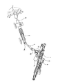
図1〜3は、本発明の実施例を示している。本実施例の電動式パワーステアリング装置は、前述の図6に示した従来構造のコラムアシスト式の電動式パワーステアリング装置に、本発明を適用している。図1は、本実施例の電動式パワーステアリング装置の下部を構成する、ピニオン軸6とラック9との噛合部と、このピニオン軸6の回転支持部とを、一部を省略して示している。又、図2〜3は、このピニオン軸6の回転支持部のうち、使用時に上端側となる、ステアリングホイール1(図6等参照)側の回転支持部を構成する玉軸受22を取り出して示している。図1〜3に示した構造以外の部分は、前述の図6に示した従来構造と同様である為、重複する図示並びに説明は省略し、以下本実施例の特徴部分を中心に説明する。
1 to 3 show an embodiment of the present invention. The electric power steering apparatus of the present embodiment applies the present invention to the column-assisted electric power steering apparatus having the conventional structure shown in FIG. FIG. 1 shows a part of the meshing part of the pinion shaft 6 and the
上記ラック9はその中間部を図示しないハウジングに、軸方向(図1の表裏方向)の変位自在に支持され、軸方向に変位する事で操舵輪に舵角を付与する。上記ピニオン軸6は、ステアリングホイール1側の玉軸受22と、このステアリングホイール1から遠い側のニードル軸受23とにより、軸方向に離隔した2個所位置を、上記ハウジングに対し回転自在に支持している。又、上記ピニオン軸6の中間部で上記両軸受22、23の間部分に形成したピニオン8を、上記ラック9と噛合させている。このピニオン軸6の上端部は、自在継手3bを介して、中間軸4(図6参照)に連結している。
The
又、本実施例の場合には、上記ラック9に関して上記ピニオン軸6と反対側に、押圧部材24を設けている。この押圧部材24は、その片面に断面円弧形の凹面部25を形成しており、この凹面部25を上記ラック9の外周面に弾性的に押し付けている。この為に、本実施例の場合には、上記押圧部材24と上記ハウジングに固定の部材との間に、弾性部材である圧縮コイルばね26と、アジャストスクリュー27とを設けている。この構成により、上記ラック9の歯面の一部が上記ピニオン8の歯面に弾性的に押し付けられ、これら両部材9、8の噛合部でのがたつきの発生が阻止される。尚、上記アジャストスクリュー27は、上記ラック9に付与する弾力の大きさを調節自在とする役目を果たす。
In this embodiment, a pressing
特に、本実施例の場合、上記1対の軸受22、23のうち、ステアリングホイール1側の軸受である玉軸受22は、図2〜3に詳示する様に、内輪28と、外輪29と、複数の玉30、30と、保持器31とを備える。このうちの内輪28は、中央で2分割した1対の素子を一体に重ね合わせた如き構成を有する。即ち、この内輪28は、第一の内輪素子32a及び第二の内輪素子32bを、その一端面同士を重ね合わせる事により構成しており、これら各内輪素子32a、32bの外周面に、それぞれ半円を中央で2分割した如き断面形状を有する第一、第二の内輪軌道33a、33bを形成している。又、これら各内輪軌道33a、33bの断面形状は、図3に示す様に上記両内輪素子32a、32bを重ね合わせた状態で重ね合わせ面から互いに軸方向に同じ量だけずれた位置にある曲率中心o1 、o2 をそれぞれの中心とした、各玉30、30の直径Da の1/2よりも大きな、互いに同じ大きさの曲率半径rを有する円弧である。この為、上記各内輪軌道33a、33bは、互いに上記重ね合わせ面を含む仮想平面に関して対称な形状となっている。そして、上記両内輪素子32a、32bの一端面同士を重ね合わせた状態で、上記各内輪軌道33a、33bの一端縁同士を一致させる事により内輪軌道34を構成している。この為、この内輪軌道34の断面形状は、1対の円弧同士を中間部で交差させた、所謂ゴシックアーチ状となる。
In particular, in the case of the present embodiment, among the pair of
一方、上記外輪29は、内周面に、上記内輪軌道34と対向する外輪軌道35を形成している。この外輪軌道35の断面形状は、上記各玉30、30の直径Da の1/2よりも大きな曲率半径を有する円弧同士を中間部で交差させた、所謂ゴシックアーチ状である。又、上記保持器31は、両端側に設けた1対の円環状のリム部の円周方向複数個所同士を、複数本の柱部により連結して成る。そして、これらリム部及び柱部の側面により、上記保持器31の円周方向複数個所にポケット36を形成している。又、この保持器31は、複数の型を径方向に遠近動させる事により対象となる製品を造る、ラジアルドロー方式により、合成樹脂を射出成形する事により造っている。そして、上記外輪軌道35と内輪軌道34との間に、複数の玉30、30を転動自在に設けると共に、これら各玉30、30を、上記保持器31に設けた複数のポケット36内に保持している。この様な構成により、前記玉軸受22は、上記各玉30、30の転動面と外輪軌道35及び内輪軌道34とが、それぞれ2点ずつ、これら各玉30、30毎に合計4点ずつ接触する4点接触型となる。尚、上記保持器31を造るのにラジアルドロー方式を採用しているのは、1対の円環状のリム部を複数本の柱部により連結して成る構造で、径方向厚さを小さくする場合に、最も適した方式である為である。
On the other hand, the
更に、本実施例の場合には、上記外輪29の内周面で上記外輪軌道35よりも両端側に外れた部分に設けた外径側肩部37、37の最小内径部の内径をde とし、前記内輪28の外周面で上記内輪軌道34よりも両端側に外れた部分に設けた内径側肩部38、38の最大外径部の外径をDi とし、上記各玉30、30の直径をDa とした場合に、Da >(de −Di )を満たす様に、各部の寸法を規制している。更に、これら各玉30、30を保持する保持器31を、上記外径側肩部37、37の内周面によりその回転を案内する、外輪29案内型としている。又、本実施例の場合には、上記外輪29の両端部内周面と上記内輪28の両端部外周面との間に、それぞれが密封部材である1対のシールド板41、41を設けている。そして、これら各シールド板41、41により、玉軸受22の内部空間に塵芥等の異物が浸入する事を防止すると共に、グリース等の潤滑剤が外部に飛散する事を防止している。但し、この様な考慮が不要である場合には、上記各シールド板41、41等の密封部材を省略する事もできる。
Further, in the case of this embodiment, the inner diameter of the minimum inner diameter portion of the outer diameter side shoulders 37, 37 provided in a portion deviated on both ends than the
上述の様に構成する4点接触型の玉軸受22は、前記ハウジングの内周面とピニオン軸6の外周面との間に固定している。又、本実施例の場合には、このピニオン軸6の一部外周面に設けたかしめ部39と、段部40との間で、上記内輪28を挟持している。
The four-point contact
上述の様に構成する本実施例の電動式パワーステアリング装置によれば、ピニオン軸6を支持する1対の軸受のうちのステアリング1側の軸受を、内輪28を、それぞれの内輪軌道33a、33bが互いに重ね合わせ面を含む仮想平面に関して対称な形状である1対の内輪素子32a、32bを一体に重ね合わせる事により構成した玉軸受22としている。この為、内輪28及び外輪29をそれぞれ単一の部材により構成した軸受を使用する従来構造の場合と異なり、内輪28の外周面と外輪29の外周面との間に各玉30、30を組み込む場合に、この内輪28をこの外輪29に対し大きく偏心させつつこの間部分が大きくなった円周方向一部を通じて、玉軸受22の内側に玉30、30を組み込む事を行なう必要がなくなる。即ち、本発明の場合には、玉軸受22に玉30、30を組み込む場合に、内輪28の側から1対の内輪素子32a、32bを軸方向に離隔させた状態で、上記間部分に径方向に玉30、30を組み込む事ができる。この為、上記玉軸受22に組み込む玉30、30の数を多くでき、結果として、この玉軸受22の負荷能力を高くできる。しかも、上記内輪28の両端部外周面に設けた内径側肩部38、38と、上記外輪29の両端部内周面に設けた外径側肩部37、37との高さを大きくできる為、これら各肩部38、37への各玉30、30の乗り上げを生じにくくできる。この為、上記玉軸受22の耐久性の向上を図れる。この結果、本発明によれば、使用時に上記ピニオン軸6に大きな入力トルクが付与されるのにも拘らず、負荷能力及び耐久性を十分に確保でき、且つ、高効率な構造を得られる。
According to the electric power steering apparatus of the present embodiment configured as described above, of the pair of bearings that support the pinion shaft 6, the
又、上記玉軸受22に組み込む玉30、30の数を多くできる為、各玉30、30の直径Da に対する外輪軌道35及び内輪軌道34の曲率半径rの比(r/Da 、r/de を大きくした場合でも、負荷能力を十分に確保し易くなる。即ち、この比を大きくする程各玉30、30の転動面と外輪、内輪各軌道35、34との接触部の接触面積は小さくなり、この接触部に作用する接触面圧は高くなる傾向になる。この為、上記比を大きくする場合には、一般的に負荷能力が低下する。これに対して、本発明の場合には、組み込む玉30、30の数を多くできる為、上記比を大きくした場合でも、負荷能力を十分に確保し易くなる。従って、この比を大きくする様に設計できる分、上記各玉30、30の転動面と外輪軌道35及び内輪軌道34との接触部に形成される接触楕円の面積を小さくし、軸受損失を小さくして、電動式パワーステアリング装置の性能の向上を図れる。又、上記比を大きくする様に設計できる分、上記各肩部37、38への上記各玉30、30の乗り上げを、より生じにくくできる。
Further, since the number of
又、前記ピニオン軸6を支持する1対の軸受のうち、使用時に上端側となる側の軸受を、上述の様な4点接触型の玉軸受22としている為、本実施例の様に、使用時に下端側となるステアリング1から遠い側の軸受として、ニードル軸受23等、径方向寸法を小さくできる軸受を使用する事ができ、自動車のエンジンルーム内へ各部品を最適な状態に配置し(最適レイアウトし)易くなる。
Further, among the pair of bearings that support the pinion shaft 6, the bearing on the upper end side in use is the four-point contact
又、本実施例の場合には、上記玉軸受22を構成する内輪28を、1対の内輪素子32a、32bを一体に重ね合わせる事により構成している為、前記ピニオン軸6にこの内輪28を精度良く取り付ける事を容易に行なえる。即ち、本実施例の場合と異なり、上記玉軸受22の代わりに、外輪29を、1対の外輪素子を一体に重ね合わせる事により構成した玉軸受を使用する場合には、これら各外輪素子の内周面に設けた外輪軌道の一端縁同士を正確に一致させるべく、これら各外輪素子を、ピニオン軸6の周囲に設けるハウジングに高精度に内嵌する必要がある。但し、このハウジングは、アルミニウム合金等の金属をダイカスト成形する事により造る場合が多く、このハウジングの内周面を高精度に加工する事は、コストが著しく高くなる面から難しい。又、このハウジングは、普通切削仕上により仕上加工する場合が多く、外輪29との嵌め合いは、隙間嵌めにする場合が多い。この様な理由から、コストの上昇を抑えつつ、各外輪素子を上記ハウジングに高精度に内嵌する事は難しい。
In the case of the present embodiment, the
これに対して、内輪28を、1対の内輪素子32a、32bを一体に重ね合わせる事により構成した本実施例の場合には、この様な問題が生じない。即ち、これら各内輪素子32a、32bは、ピニオン軸6に対し強い締り嵌めにより外嵌したり、本実施例の様に、かしめ等の方法によりピニオン軸6に対し相対回転を不能に固定する場合が多い。又、コストの上昇を抑えつつ、ピニオン軸6の外周面を高精度に仕上げる事は容易に行なえる。この為、1対の内輪素子32a、32bの外周面に設けた内輪軌道33a、33bの一端縁同士を一致させるべく、これら各内輪素子32a、32bを上記ピニオン軸6に高精度に外嵌する事は、1対の外輪素子を上記ハウジングに高精度に内嵌する場合よりも、コストを高くする事なく、且つ、容易に行なえる。そこで、本実施例では、上記内輪28を、上記1対の内輪素子を32a、32bを一体に重ね合わせる事により構成している。
On the other hand, in the case of the present embodiment in which the
又、本実施例の場合には、外輪29の両端部内周面に設けた外径側肩部37、37の最小内径部の内径をde とし、内輪28の両端部外周面に設けた内径側肩部38、38の最大外径部の外径をDi とし、各玉の直径をDa とした場合に、Da >(de −Di )を満たす様に各部の寸法を規制している。この為、上記各外径側肩部37、37及び内径側肩部38、38の高さが相対的に大きくなる為、玉30、30の乗り上げをより生じにくくでき、玉軸受22の耐久性をより向上できる。
Further, in the case of the embodiment, the inner diameter of the minimum inner diameter portion of the outer diameter side shoulders 37, 37 provided at both ends in the peripheral surface of the
更に、本実施例の場合には、各玉30、30を保持する保持器31を、外輪29の内周面によりその回転を案内するラジアルドロー方式により造った、合成樹脂製としている。この為、合成樹脂製の冠型保持器により上記各玉30、30を保持する場合と異なり、保持器31の厚さ(径方向寸法)を十分に小さくできる。従って、外輪29の両端部内周面に設けた外径側肩部37、37と、内輪28の両端部外周面に設けた内径側肩部38、38との高さを、より大きくでき、玉軸受22の耐久性をより向上できる。又、保持器31を外輪29案内としている為、本実施例の様に内輪28を1対の内輪素子32a、32bを重ね合わせる事により構成する場合に、外輪29の内径側に配置した保持器31の内径側から、この保持器31の複数のポケット36に各玉30、30を組み込む作業を容易に行なえる。又、保持器31を合成樹脂製としている為、金属をプレス加工する事により造った保持器を組み込む場合と異なり、保持器31の外周面と上記外輪29の内周面との間での摩擦を抑える事ができ、電動式パワーステアリング装置の性能の向上を図れる。
Further, in the case of the present embodiment, the cage 31 for holding the
次に、上述した本実施例により得られる効果を確認すべく行なったシミュレーションの結果に就いて説明する。このシミュレーションは、上述の図2〜3に示した玉軸受22によりピニオン軸6を支持する電動式パワーステアリング装置と同様の構造を有する実施品と、図4に示す玉軸受22aによりピニオン軸6を支持する従来構造の電動式パワーステアリング装置の比較品とを用いて、軸受損失と各玉30、30の肩部37、38への乗り上げ率ρとを数値解析により予測した。又、上記実施品に組み込む玉軸受22の諸元は次の通りである。
外輪29の外径De −−− 42mm
内輪28の内径di −−− 18mm
各内輪素子32a、32bの幅B1 −−− 6.5mm
内輪28及び外輪29の幅B2 −−− 13mm
外輪29に設けた外径側肩部37、37の最小内径部の内径de
−−− 31.9mm
内輪28に設けた内径側肩部38、38の最大外径部の外径Di
−−− 29.1mm
内輪、外輪各軌道34、35の曲率半径r
−−− 3.643mm
各玉30、30の直径Da −−− 6.74688mm
玉の数n −−− 11個
接触角α −−− 20°
各玉30、30の直径Da に対する内輪、外輪各軌道34、35の曲率半径rの割合
−−− 54%
複数の玉30、30のピッチ円直径D30
−−− 30.5mm
Next, the result of simulation performed to confirm the effect obtained by the above-described embodiment will be described. In this simulation, the pinion shaft 6 is mounted by an embodiment product having the same structure as the electric power steering device that supports the pinion shaft 6 by the
Inner ring inner diameter d i ---- 18 mm
Width B 1 of each
Width B 2 of
The inner diameter d e of the minimum inner diameter portion of the outer diameter side shoulders 37, 37 provided on the
---- 31.9mm
The outer diameter D i of the maximum outer diameter portion of the inner diameter
---- 29.1 mm
Radius of curvature r of inner ring and
--- 3.643mm
Diameter of each
Number of balls n --- 11 pieces Contact angle α ---- 20 °
The inner ring to the diameter D a of each
---- 54%
The pitch circle diameter D 30 of the
---- 30.5mm
上述の諸元から明らかな通り、実施品の玉軸受22は、Da (=6.74688)>de −Di (=2.8)の関係を満たしている。又、複数の玉30、30のピッチ円直径D30を上記諸元の様に規制する場合に好ましくは、組み込む玉30、30の数を10個以上とし、より好ましくは11個以上とする。又、この玉30、30の数の上限を13個とする。この様に玉30、30の好ましい数を規制する理由は、組み込む玉30、30の数を多くする程、負荷能力を高くできる為である。又、後述する様に、比較品の玉軸受22aには8個の玉30、30を組み込める為、実施品の玉軸受22の負荷能力を比較品よりも高くする為には、玉30、30を10個以上としないと、比較品に対して顕著な効果を得られない。又、玉30、30の数nは、n<{(D30×π)/Da }の関係を満たす必要がある。そこで、玉30、30の好ましい数の範囲を上述の様に規制した。この為、本発明を実施する場合に好ましくは、玉軸受22に組み込む玉30、30の数を10個以上とし、より好ましくは、n<{(D30×π)/Da }を満たす最大の整数個とする。又、この様に多くの玉30、30を組み込める為、玉軸受22の負荷能力を高くでき、その分、各玉30、30の直径Da に対する内輪、外輪各軌道34、35の曲率半径rの割合を、54%と大きくした。この割合を大きくした場合でも、玉軸受22の負荷能力を十分に確保できる。又、この割合を大きくできる分、摩擦損失を小さくでき、電動式パワーステアリング装置の性能の向上を図れる。更に、内径側、外径側各肩部38、37への玉30、30の乗り上げをより生じにくくでき、耐久性の向上を図れる。尚、上記各軌道34、35の曲率半径が過大になると、これら各軌道34、35と各玉30、30との接触部での面圧が過大になり、軸受寿命の低下を招く。この事から、各玉30、30の直径Da に対する各軌道34、35の曲率半径rの割合r/Da は、52%を越え、60%以下とする事が好ましい。これに対して、この割合が60%を越えると、軸受寿命の低下が著しくなる。より好ましくは、上記直径Da に対する上記曲率半径rの割合r/Da は、53%以上58%以下とする。
As is clear from the above-mentioned specifications, the
一方、前記比較品を構成する玉軸受22aは、図4に示す様に、内輪28aと外輪29とをそれぞれ単一の部材により構成した4点接触型である。この様な玉軸受22aでは、上記実施品の玉軸受22の場合と異なり、組み込み可能な玉30、30の数が少なくなる。シミュレーションに使用する玉軸受22aの玉30、30の数n´は、最大限に組み込み可能な数である8個とした。比較品を構成する玉軸受22aの諸元で、この数n´以外に上記実施品の玉軸受22の場合と異なるものは次の通りである。
外輪29の両端部内周面に設けた外径側肩部37a、37aの最小内径部の内径de ´
−−− 34.4mm
内輪28aの両端部外周面に設けた内径側肩部38a、38aの最大外径部の外径Di ´ −−− 26.6mm
内輪、外輪各軌道34、35の曲率半径r´ −−− 3.508mm
接触角α´ −−− 35°
各玉30、30の直径Da に対する内輪、外輪各軌道34、35の曲率半径r´の割合
−−− 52%
各玉30、30の直径Da −−− 6.74688mm
On the other hand, as shown in FIG. 4, the
Inner diameter d e ′ of the smallest inner diameter portion of outer
---- 34.4mm
The outer diameter D i 'of the maximum outer diameter portion of the inner diameter
Radius of curvature r ′ of inner and
Contact angle α ′ −−− 35 °
The ratio of the radius of curvature r ′ of the inner and
---- 52%
Diameter of each
上述の諸元から明らかな通り、比較品の玉軸受22aは、Da <de ´−Di ´の関係を満たしている。この理由は、玉30、30を組み込む場合に、内輪28aを外輪29に対し大きく偏心させつつ玉軸受22aの側方から、上記内径側肩部38aの外周面と外径側肩部37aの内周面との間部分を通じて、内側に玉30、30を組み込む必要がある為である。又、組み込む玉30、30の数が8個と少ない為、玉軸受22aの負荷能力をその分大きくする必要があり、内輪、外輪各軌道34、35の曲率半径r´を小さくしている。そして、各玉30、30の直径Da に対するこの曲率半径r´の割合を、52%と小さくしている。又、これに伴って、接触角α´は、35°と大きくなっている。
As is apparent from the above specifications, the
シミュレーションは、それぞれが上述の様な諸元を有する玉軸受22、22aを組み込んだ、実施品と比較品との電動式パワーステアリング装置を用いて、ピニオン軸6(図1)に加わる入力トルクを種々に異ならせた場合での、玉軸受22、22aで発生する摩擦トルクと、各玉30、30の肩部37、37a、38、38aへの乗り上げ率ρとを、数値解析で予測した。尚、この乗り上げ率ρは、次の様に定義する。先ず、各玉30、30の直径Da、各軌道34、35の形状、材料物性、玉軸受22、22aに付与される荷重を基に、Hertzの点接触理論の計算式を用いて、図5に斜格子で示す様な、各玉30と各軌道34、35との転がり接触部での接触楕円を求める。次いで、この接触楕円の長軸方向の長さL1 と、この接触楕円のうち、肩部38、37の幅方向端縁部分に乗り上げた(端縁部分からはみ出した)部分の長軸方向の長さL2 とを求める。そして、これら長さL1 、L2 の比を、各玉30、30の乗り上げ率ρ(=L2 /L1 )とした。又、上記数値解析として、非特許文献1に記載されている方法を使用した。この様な条件で、ピニオン軸6に加わる入力トルクを70Nm、55Nm、40Nmの3種類に異ならせつつ、シミュレーションした結果を、次の表1に示している。
In the simulation, the input torque applied to the pinion shaft 6 (FIG. 1) is calculated by using the electric power steering device of the implementation product and the comparison product, each incorporating the

この表1に示したシミュレーションの結果から明らかな通り、実施品の場合には、比較品の場合に対して、摩擦トルクを2/3程度に小さくできると共に、各玉30の乗り上げ率ρを25%以下に低下させる事ができた。この様なシミュレーションの結果から明らかな通り、本発明によれば、負荷能力が高く、且つ、高効率な電動式パワーステアリング装置を得られる事を確認できた。
As is apparent from the results of the simulation shown in Table 1, in the case of the actual product, the friction torque can be reduced to about 2/3 as compared with the comparative product, and the running rate ρ of each
尚、上述した実施例は、コラムアシスト式の電動式パワーステアリング装置に本発明を適用した場合に就いて説明した。但し、本発明は、この様な構造に限定するものではなく、例えば、前述の図7に示した様なピニオンアシスト式の電動式パワーステアリング装置や、前述の図8に示した様な、デュアルピニオン式の電動式パワーステアリング装置に、本発明を適用する事もできる。例えば、図7に示したピニオンアシスト式の電動式パワーステアリング装置に本発明を適用する場合、ラック9と噛合するピニオンをその外周面に形成した、ピニオン軸の回転支持部のうち、ステアリングホイール1側の回転支持部を構成する軸受を、前述の図2〜3に示した様な4点接触型の玉軸受22とする。又、このピニオン軸の一部にウォーム減速機を構成するウォームホイールを外嵌固定すると共に、このピニオン軸に、このウォーム減速機を介して、電動モータ12の補助力を付与する様にする。
In the above-described embodiment, the case where the present invention is applied to a column assist type electric power steering apparatus has been described. However, the present invention is not limited to such a structure. For example, the pinion assist type electric power steering device as shown in FIG. 7 or the dual power as shown in FIG. The present invention can also be applied to a pinion type electric power steering apparatus. For example, when the present invention is applied to the pinion assist type electric power steering apparatus shown in FIG. 7, the
又、図8に示したデュアルピニオン式の電動式パワーステアリング装置に本発明を適用する場合、ラック9の一部でピニオン軸6のピニオンから外れた部分に、第二のピニオン軸16を配置すると共に、この第二のピニオン軸16の回転支持部のうち、ステアリングホイール1側の回転支持部を構成する軸受を、図2〜3に示した様な4点接触型の玉軸受22とする。又、上記第二のピニオン軸16の一部にウォーム減速機を構成するウォームホイールを外嵌固定すると共に、この第二のピニオン軸に、このウォーム減速機を介して、電動モータ12の補助力を付与する様にする。
Further, when the present invention is applied to the dual pinion type electric power steering apparatus shown in FIG. 8, the
1 ステアリングホイール
2 ステアリングシャフト
3a、3b 自在継手
4 中間軸
5 ステアリングギヤ
6 ピニオン軸
7 ハウジング
8 ピニオン
9 ラック
10 ステアリングコラム
11 ギヤハウジング
12 電動モータ
13 タイロッド
14 入力軸
15 ギヤハウジング
16 第二のピニオン軸
17 ハウジング
18 減速機
22、22a 玉軸受
23 ニードル軸受
24 押圧部材
25 凹面部
26 圧縮コイルばね
27 アジャストスクリュ−
28、28a 内輪
29 外輪
30 玉
31 保持器
32a 第一の内輪素子
32b 第二の内輪素子
33a 第一の内輪軌道
33b 第二の内輪軌道
34 内輪軌道
35 外輪軌道
36 ポケット
37、37a 外径側肩部
38、38a 内径側肩部
39 かしめ部
40 段部
41 シールド板
DESCRIPTION OF
28,
Claims (5)
The electric ball according to any one of claims 1 to 4, wherein each ball is slidably held by a synthetic resin cage made by injection molding of a radial draw method that guides the rotation by the inner peripheral surface of the outer ring. Power steering device.
Priority Applications (1)
| Application Number | Priority Date | Filing Date | Title |
|---|---|---|---|
| JP2004110627A JP2005289298A (en) | 2004-04-05 | 2004-04-05 | Electric power steering device |
Applications Claiming Priority (1)
| Application Number | Priority Date | Filing Date | Title |
|---|---|---|---|
| JP2004110627A JP2005289298A (en) | 2004-04-05 | 2004-04-05 | Electric power steering device |
Publications (2)
| Publication Number | Publication Date |
|---|---|
| JP2005289298A true JP2005289298A (en) | 2005-10-20 |
| JP2005289298A5 JP2005289298A5 (en) | 2007-05-17 |
Family
ID=35322734
Family Applications (1)
| Application Number | Title | Priority Date | Filing Date |
|---|---|---|---|
| JP2004110627A Pending JP2005289298A (en) | 2004-04-05 | 2004-04-05 | Electric power steering device |
Country Status (1)
| Country | Link |
|---|---|
| JP (1) | JP2005289298A (en) |
Cited By (4)
| Publication number | Priority date | Publication date | Assignee | Title |
|---|---|---|---|---|
| JP2010149573A (en) * | 2008-12-24 | 2010-07-08 | Jtekt Corp | Electric power steering device |
| JP2014015124A (en) * | 2012-07-09 | 2014-01-30 | Jtekt Corp | Steering device and method of manufacturing the same |
| JP2014238141A (en) * | 2013-06-07 | 2014-12-18 | 日本精工株式会社 | Worm reduction gear and dual pinion type electric power steering device |
| JP2019537694A (en) * | 2016-11-09 | 2019-12-26 | ローベルト ボツシユ ゲゼルシヤフト ミツト ベシユレンクテル ハフツングRobert Bosch Gmbh | Fixed bearings and steering gears |
-
2004
- 2004-04-05 JP JP2004110627A patent/JP2005289298A/en active Pending
Cited By (4)
| Publication number | Priority date | Publication date | Assignee | Title |
|---|---|---|---|---|
| JP2010149573A (en) * | 2008-12-24 | 2010-07-08 | Jtekt Corp | Electric power steering device |
| JP2014015124A (en) * | 2012-07-09 | 2014-01-30 | Jtekt Corp | Steering device and method of manufacturing the same |
| JP2014238141A (en) * | 2013-06-07 | 2014-12-18 | 日本精工株式会社 | Worm reduction gear and dual pinion type electric power steering device |
| JP2019537694A (en) * | 2016-11-09 | 2019-12-26 | ローベルト ボツシユ ゲゼルシヤフト ミツト ベシユレンクテル ハフツングRobert Bosch Gmbh | Fixed bearings and steering gears |
Similar Documents
| Publication | Publication Date | Title |
|---|---|---|
| CN100519300C (en) | Electric-powered power steering apparatus | |
| US10787195B2 (en) | Electric power steering system | |
| US20060156855A1 (en) | Telescopic shaft for motor vehicle steering | |
| EP1693579A2 (en) | Telescopic shaft | |
| JP6268711B2 (en) | Multi-point contact ball bearing and manufacturing method thereof | |
| US20060082120A1 (en) | Telescopic shaft for motor vehicle steering | |
| EP3020991A1 (en) | Telescopic shaft | |
| JP2008185062A (en) | Load supporting device | |
| EP1878929A1 (en) | Rolling bearing | |
| JP5235392B2 (en) | Double row angular contact ball bearings | |
| JP2005289298A (en) | Electric power steering device | |
| DE112007003354A5 (en) | Longitudinal drive shaft for motor vehicles | |
| CN100570177C (en) | Improved preloaded ball screw with multiple spot Gothic arch section thread contour | |
| JP2007321939A (en) | Bearing assembling method, rolling bearing, and cage for bearing | |
| JP2006044375A (en) | Electric power steering device | |
| JP2011149551A (en) | Tripod constant-velocity universal joint | |
| JP2000055069A (en) | Constant velocity joint | |
| KR20160103564A (en) | Wheel bearing | |
| JP3941239B2 (en) | Constant velocity joint | |
| JP2018035912A (en) | Ball screw device, and steering device including ball screw device | |
| JP5004312B2 (en) | Koma type ball screw | |
| JP2004183828A (en) | Worm shaft supporting device and power assist unit | |
| JP2004218790A (en) | Bearing device for steering column | |
| JP2007239878A (en) | Drive shaft boot | |
| US20200158166A1 (en) | Automotive differential gear and automotive transmission |
Legal Events
| Date | Code | Title | Description |
|---|---|---|---|
| A521 | Written amendment |
Free format text: JAPANESE INTERMEDIATE CODE: A523 Effective date: 20070328 |
|
| A621 | Written request for application examination |
Free format text: JAPANESE INTERMEDIATE CODE: A621 Effective date: 20070328 |
|
| RD04 | Notification of resignation of power of attorney |
Free format text: JAPANESE INTERMEDIATE CODE: A7424 Effective date: 20070328 |
|
| A131 | Notification of reasons for refusal |
Free format text: JAPANESE INTERMEDIATE CODE: A131 Effective date: 20090728 |
|
| A02 | Decision of refusal |
Free format text: JAPANESE INTERMEDIATE CODE: A02 Effective date: 20091201 |