JP2005253300A - Ac motor driving device - Google Patents
Ac motor driving device Download PDFInfo
- Publication number
- JP2005253300A JP2005253300A JP2005145762A JP2005145762A JP2005253300A JP 2005253300 A JP2005253300 A JP 2005253300A JP 2005145762 A JP2005145762 A JP 2005145762A JP 2005145762 A JP2005145762 A JP 2005145762A JP 2005253300 A JP2005253300 A JP 2005253300A
- Authority
- JP
- Japan
- Prior art keywords
- motor
- power
- short circuit
- current
- circuit
- Prior art date
- Legal status (The legal status is an assumption and is not a legal conclusion. Google has not performed a legal analysis and makes no representation as to the accuracy of the status listed.)
- Pending
Links
Images
Landscapes
- Control Of Ac Motors In General (AREA)
- Maintenance And Inspection Apparatuses For Elevators (AREA)
- Elevator Door Apparatuses (AREA)
Abstract
Description
本発明は、交流電動機駆動装置に関する。 The present invention relates to an AC motor drive device.
従来、エレベータ駆動装置が故障したり、電源喪失が発生してエレベータを緊急停止させた場合、また停電や故障が発生してかご内部に乗客が閉じ込められた場合、救出階に安全に移動するまでは簡単にドアが開かないようにする対策がとられている。 Conventionally, if the elevator drive system fails or the elevator loses power due to loss of power, or if a power outage or malfunction occurs and passengers are trapped inside the car, it will be safe to move to the rescue floor Measures are taken to prevent the door from opening easily.
非常時にエレベータドアが開かないようにする方式には、ドア開閉駆動用の電動機のタイプにより複数の方式がある。その一つは、電磁ブレーキを使用する方式である。この方式は、電動機のタイプを問わずに実施可能である。 There are a plurality of methods for preventing the elevator door from being opened in an emergency, depending on the type of electric motor for door opening / closing drive. One of them is a method using an electromagnetic brake. This method can be implemented regardless of the type of electric motor.
図5に電磁ブレーキを使用したときの電動機駆動装置の構成を示している。これは、直流電源1により平滑コンデンサ2を介して電力制御装置3に電力を供給し、この電力制御装置3の直流出力によって電動機4を回転駆動し、エレベータドア6を開閉駆動する構成である。そして電力制御装置3を制御するときには、ブレーキ制御リレー23をオンしてブレーキ回路に電流を流し、電磁ブレーキ21を開路し、電動機4の回転駆動を可能にする。また電力制御装置3の制御を停止した場合又は停電時にはブレーキ制御リレー23をオフさせてブレーキ回路に電流を流れなくし、電磁ブレーキ21を働かせて電動機4を停止させ、エレベータドア6の開閉駆動も停止させる。
FIG. 5 shows the configuration of the electric motor drive device when the electromagnetic brake is used. This is a configuration in which power is supplied to the
電動機駆動装置の別の方式は、永久磁石直流電動機を駆動力とするドア駆動装置に適用されるもので、永久磁石直流電動機の端子をアマチュア短絡し、制動力を得る方式である。 Another method of the electric motor drive device is applied to a door drive device using a permanent magnet DC motor as a driving force, and is a method of obtaining a braking force by short-circuiting the terminals of the permanent magnet DC motor.
図6及び図7にアマチュア短絡回路を使用したときの直流電動機駆動装置の構成を示している。これは、直流電源1により電力制御装置3に電力を供給し、この電力制御装置3の直流出力を電動機4に供給して回転させ、エレベータドア6を開閉駆動する構成であり、電力制御装置3の直流出力側に永久磁石直流電動機4と並列に、B接点リレー5と電流制限抵抗7を有するアマチュア短絡回路を設けている。そして、電力制御装置3を制御するときにはB接点リレー5をオン(開路動作)させてアマチュア短絡回路をオープンし、電力制御装置3の出力を永久磁石直流電動機4に供給して回転駆動し、エレベータドア6を開閉駆動する。
FIG. 6 and FIG. 7 show the configuration of a DC motor driving device when an amateur short circuit is used. This is a configuration in which power is supplied to the
また、電力制御装置3の制御を停止した場合又は停電時には、B接点リレー5をオフ(閉路動作)させ、永久磁石直流電動機4の端子を制限抵抗7を介して短絡させることにより発電制動力を発生させて永久磁石直流電動機4を停止させ、エレベータドア6の開閉駆動も停止させる。なお、図7において11は電動機4の内部リアクトル、12は内部抵抗、13は制動発電機である。
In addition, when the control of the
しかしながら、従来の電磁ブレーキを設ける方式の電動機駆動装置の場合、コスト面、電動機の大型化等の面で問題点があった。 However, in the case of a conventional motor drive device having an electromagnetic brake, there are problems in terms of cost, increase in size of the motor, and the like.
また、アマチュア短絡回路により永久磁石直流電動機の端子を短絡させて発電制動する直流電動機駆動装置は、直流電動機には適用できても、永久磁石同期電動機のような交流電動機には適用できなかった。 Further, a DC motor driving device that short-circuits a terminal of a permanent magnet DC motor by an amateur short circuit and can perform dynamic braking can be applied to a DC motor but cannot be applied to an AC motor such as a permanent magnet synchronous motor.
本発明はこのような従来の問題点に鑑みてなされたもので、永久磁石同期電動機のような交流電動機においてアマチュア短絡回路を構成し、制御不能時に交流電動機を効果的に制動することができる交流電動機駆動装置を提供することを目的とする。 The present invention has been made in view of such conventional problems. An AC short circuit is formed in an AC motor such as a permanent magnet synchronous motor, and an AC motor that can effectively brake the AC motor when it cannot be controlled. An object is to provide an electric motor drive device.
また、永久磁石同期電動機のような交流電動機においてアマチュア短絡回路を構成した場合、直流電動機と異なり、電動機発電電圧の位相制御ができないために力率が下がり、制動力が低下することがあるが、本発明はその問題点を解決した交流電動機駆動装置を提供することを目的とする。 Also, when an amateur short circuit is configured in an AC motor such as a permanent magnet synchronous motor, unlike a DC motor, the power factor is lowered because the phase control of the motor generated voltage cannot be performed, and the braking force may be reduced. An object of this invention is to provide the alternating current motor drive device which solved the problem.
請求項1の発明の交流電動機駆動装置は、直流電源の直流電力を交流電力に変換する電力変換装置と、この電力変換装置の交流電力によって回転駆動される交流電動機と、前記電力変換装置の交流出力側に設けられ、前記電力変換装置の制御停止時に前記交流電動機をアマチュア短絡させ、制動力を発生させるアマチュア短絡回路とを備え、前記アマチュア短絡回路には、前記アマチュア短絡時の電流位相を進めることによって前記交流電動機の力率を改善し、必要な制動力を確保するための進相コンデンサを直列に挿入したことを特徴とするものである。 An AC motor drive device according to a first aspect of the present invention is a power conversion device that converts DC power of a DC power source into AC power, an AC motor that is rotationally driven by the AC power of the power conversion device, and an AC of the power conversion device. An amateur short circuit that is provided on the output side and shorts the AC motor when the control of the power converter is stopped and generates a braking force, and advances the current phase at the time of the amateur short circuit. Thus, a phase advance capacitor for improving the power factor of the AC motor and ensuring a necessary braking force is inserted in series.
請求項2の発明は、請求項1の交流電動機駆動装置において、前記アマチュア短絡回路には、前記アマチュア短絡時の電流を制限して前記交流電動機を最大定格電流以下とするための電流制限抵抗と、電流位相を進めることによって前記交流電動機の力率を改善するための進相コンデンサとを直列に挿入したことを特徴とするものである。 According to a second aspect of the present invention, in the AC motor drive device according to the first aspect, the amateur short circuit includes a current limiting resistor for limiting a current at the time of the amateur short circuit so that the AC motor is equal to or lower than a maximum rated current. A phase advance capacitor for improving the power factor of the AC motor by advancing the current phase is inserted in series.
本発明によれば、電力変換装置の交流出力側に、電力変換装置の制御停止時に構成されるアマチュア短絡回路を設けることにより、電力変換装置の制御停止時には交流電動機をアマチュア短絡させ、制動力を発生させて停止させることができる。加えて、進相コンデンサによってアマチュア短絡時の電流位相を進めることによって力率を改善し、必要な制動力を確保することができる。 According to the present invention, by providing an amateur short circuit configured when the control of the power converter is stopped on the AC output side of the power converter, the AC motor is short-circuited when the control of the power converter is stopped, and the braking force is increased. It can be generated and stopped. In addition, the power factor is improved by advancing the current phase at the time of the amateur short circuit by the phase advance capacitor, and the necessary braking force can be ensured.
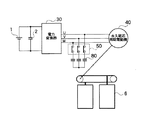
以下、本発明の実施の形態を図に基づいて詳説する。図1は本発明の第1の実施の形態の構成を示している。直流電源1から平滑コンデンサ2を介してインバータのような電力変換器30に直流電力を供給し、この電力変換器30で変換したU,V,W3相交流電力を交流電動機である永久磁石同期電動機40に供給する。
Hereinafter, embodiments of the present invention will be described in detail with reference to the drawings. FIG. 1 shows the configuration of the first embodiment of the present invention. A DC power is supplied from a DC power source 1 to a
電力変換器30の交流出力側にはB接点リレー50が接続してあり、電力変換器30のオン/オフと同期して、このB接点リレー50がオン/オフ動作し、電力変換器30がオンすると同時にB接点リレー50はオン(開路動作)し、電力変換器30の交流出力を交流電動機である永久磁石同期電動機40の各相に供給し、電力変換器30がオフすると同時にB接点リレー50がオフ(閉路動作)し、アマチュア短絡回路を構成するようにしてある。電力変換器30の交流出力側の各相には、B接点リレー50と直列に進相コンデンサ80が接続してある。
A B
次に、上記構成の交流電動機駆動装置の動作について、図2の回路を参照して説明する。電力変換器30が動作している間はB接点リレー50が開路状態にあり、電力変換器30の交流出力が永久磁石同期電動機40に供給され、永久磁石同期電動機が回転駆動してエレベータドア6を開閉駆動する。
Next, the operation of the AC motor driving apparatus having the above configuration will be described with reference to the circuit of FIG. While the
電力変換器30が停止すると同時に、図2に示す回路のように、B接点リレー50はオフ(閉路動作)し、永久磁石同期電動機40のアマチュアを短絡し、内部リアクトル110、内部抵抗120そして制動発電機130が直列に接続されたアマチュア短絡回路を構成する。このとき、永久磁石同期電動機40が制動発電機130となり、エネルギを制動発電機130の発電電圧に変換し、この電圧を内部リアクトル110、内部抵抗120、そして進相コンデンサ80によって消費し、永久磁石同期電動機4を制動し、ひいてはエレベータドア6を制動することができる。そして本実施の形態の場合、進相コンデンサ80により制動時にアマチュア短絡回路に発生する電圧と流れる電流との位相関係を制御し、力率を改善して制動力を増すことにより、電動機40を安全に停止させることができる。
At the same time when the
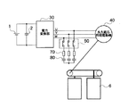
次に、本発明の第2の実施の形態の交流電動機駆動装置を図3及び図4に参照して説明する。第2の実施の形態の特徴は、図1に示した第1の実施の形態に対して、電力変換器30の交流出力の各相にB接点リレー50と直列に制限抵抗70と進相コンデンサ80とを接続した点にある。その他の構成は、図1に示した第1の実施の形態と共通する。
Next, an AC motor driving apparatus according to a second embodiment of the present invention will be described with reference to FIGS. The feature of the second embodiment is that, with respect to the first embodiment shown in FIG. 1, a
第2の実施の形態の交流電動機駆動装置の場合、電力変換器30の停止時には図4に示すようなアマチュア短絡回路が構成される。このとき、永久磁石同期電動機40が制動発電機130となり、エネルギを制動発電機130の発電電圧に変換し、この電圧を内部リアクトル110、内部抵抗120、制限抵抗70、そして進相コンデンサ80によって消費し、永久磁石同期電動機40を制動し、ひいてはエレベータドア6を制動することができる。そして第2の実施の形態の場合、制限抵抗70により制動時にアマチュア短絡回路に流れる電流が永久磁石同期電動機40の最大定格電流を超えることがないようにし、同時に進相コンデンサ80によりアマチュア短絡回路に発生する電圧と流れる電流との位相関係を制御して力率を改善して制動力を増すことができ、ひいてはエレベータドア6のドアパネルの重量が大きくなった場合でも安全に停止させることができる。
In the case of the AC motor driving device of the second embodiment, an amateur short circuit as shown in FIG. 4 is configured when the
1 直流電源
6 エレベータドア
30 電力変換器
40 永久磁石同期電動機
50 B接点リレー
70 制限抵抗
80 進相コンデンサ
110 内部リアクトル
120 内部抵抗
130 制動発電機
DESCRIPTION OF SYMBOLS 1
Claims (2)
この電力変換装置の交流電力によって回転駆動される交流電動機と、
前記電力変換装置の交流出力側に設けられ、前記電力変換装置の制御停止時に前記交流電動機をアマチュア短絡させ、制動力を発生させるアマチュア短絡回路とを備え、
前記アマチュア短絡回路には、前記アマチュア短絡時の電流位相を進めることによって前記交流電動機の力率を改善し、必要な制動力を確保するための進相コンデンサを直列に挿入したことを特徴とする交流電動機駆動装置。 A power conversion device that converts DC power of a DC power source into AC power;
An AC motor that is rotationally driven by the AC power of the power converter;
An AC short circuit provided on the AC output side of the power converter, causing the AC motor to short-circuit when control of the power converter is stopped, and generating a braking force;
The armature short circuit has a phase advance capacitor inserted in series to improve the power factor of the AC motor by advancing the current phase at the time of the armature short circuit and to secure a necessary braking force. AC motor drive device.
Priority Applications (1)
| Application Number | Priority Date | Filing Date | Title |
|---|---|---|---|
| JP2005145762A JP2005253300A (en) | 2005-05-18 | 2005-05-18 | Ac motor driving device |
Applications Claiming Priority (1)
| Application Number | Priority Date | Filing Date | Title |
|---|---|---|---|
| JP2005145762A JP2005253300A (en) | 2005-05-18 | 2005-05-18 | Ac motor driving device |
Related Parent Applications (1)
| Application Number | Title | Priority Date | Filing Date |
|---|---|---|---|
| JP2000265883A Division JP2002068632A (en) | 2000-09-01 | 2000-09-01 | Elevator door driving device |
Publications (2)
| Publication Number | Publication Date |
|---|---|
| JP2005253300A true JP2005253300A (en) | 2005-09-15 |
| JP2005253300A5 JP2005253300A5 (en) | 2006-11-16 |
Family
ID=35033244
Family Applications (1)
| Application Number | Title | Priority Date | Filing Date |
|---|---|---|---|
| JP2005145762A Pending JP2005253300A (en) | 2005-05-18 | 2005-05-18 | Ac motor driving device |
Country Status (1)
| Country | Link |
|---|---|
| JP (1) | JP2005253300A (en) |
Cited By (4)
| Publication number | Priority date | Publication date | Assignee | Title |
|---|---|---|---|---|
| CN101521483B (en) * | 2008-02-28 | 2011-11-30 | 日立空调·家用电器株式会社 | Motor driver |
| CN104602947A (en) * | 2013-01-21 | 2015-05-06 | 株式会社东芝 | Drive control device for railway vehicles |
| EP3409633A1 (en) * | 2017-05-29 | 2018-12-05 | KONE Corporation | Door operating arrangement in an elevator |
| CN115973884A (en) * | 2022-11-23 | 2023-04-18 | 菱王电梯有限公司 | Fault monitoring method and device for elevator door motor and electronic equipment |
-
2005
- 2005-05-18 JP JP2005145762A patent/JP2005253300A/en active Pending
Cited By (6)
| Publication number | Priority date | Publication date | Assignee | Title |
|---|---|---|---|---|
| CN101521483B (en) * | 2008-02-28 | 2011-11-30 | 日立空调·家用电器株式会社 | Motor driver |
| CN104602947A (en) * | 2013-01-21 | 2015-05-06 | 株式会社东芝 | Drive control device for railway vehicles |
| EP3409633A1 (en) * | 2017-05-29 | 2018-12-05 | KONE Corporation | Door operating arrangement in an elevator |
| US11279595B2 (en) | 2017-05-29 | 2022-03-22 | Kone Corporation | Door operating arrangement in an elevator |
| CN115973884A (en) * | 2022-11-23 | 2023-04-18 | 菱王电梯有限公司 | Fault monitoring method and device for elevator door motor and electronic equipment |
| CN115973884B (en) * | 2022-11-23 | 2024-08-02 | 菱王电梯有限公司 | Fault monitoring method and device for elevator door motor and electronic equipment |
Similar Documents
| Publication | Publication Date | Title |
|---|---|---|
| CN107134952B (en) | Motor drive | |
| KR100913337B1 (en) | Elevator control apparatus | |
| JP4718561B2 (en) | Actuator for elevator system | |
| EP2528226B1 (en) | Rescue operation device of elevator | |
| JP6536555B2 (en) | Motor control system and method for starting the same, and auxiliary device for motor control | |
| JP2990058B2 (en) | Emergency operation device of synchronous motor for elevator operation | |
| JPS5859179A (en) | Controller for alternating current elevator | |
| JP2005253300A (en) | Ac motor driving device | |
| JP2007166885A (en) | Electric vehicle controller | |
| JPWO2004025819A1 (en) | Induction motor control method | |
| JP5191351B2 (en) | Power converter | |
| JP2002068632A (en) | Elevator door driving device | |
| JP2010172115A (en) | Power supply method, and power supply system for ac/dc train | |
| JP5392582B2 (en) | Motor control device | |
| JP2015009954A (en) | Door controller for elevator | |
| JP2005253264A (en) | Electric rolling stock controlling device | |
| KR101036163B1 (en) | Three-phase motor driving apparatus | |
| JP2014009041A (en) | Elevator control device | |
| JP2004032913A (en) | Braking method for servomotor | |
| JPH036742B2 (en) | ||
| KR20210126362A (en) | Elevator drive system including ard | |
| JP2006176257A (en) | Elevator control device | |
| JPS5980195A (en) | Controller for elevator | |
| CN220067247U (en) | Star sealing circuit, frequency converter and elevator | |
| JP4378935B2 (en) | Electric motor control device |
Legal Events
| Date | Code | Title | Description |
|---|---|---|---|
| A521 | Written amendment |
Free format text: JAPANESE INTERMEDIATE CODE: A523 Effective date: 20061002 |
|
| A131 | Notification of reasons for refusal |
Free format text: JAPANESE INTERMEDIATE CODE: A131 Effective date: 20080520 |
|
| A02 | Decision of refusal |
Free format text: JAPANESE INTERMEDIATE CODE: A02 Effective date: 20081111 |


