JP2005247162A - Hydraulic drive type industrial vehicle - Google Patents
Hydraulic drive type industrial vehicle Download PDFInfo
- Publication number
- JP2005247162A JP2005247162A JP2004061489A JP2004061489A JP2005247162A JP 2005247162 A JP2005247162 A JP 2005247162A JP 2004061489 A JP2004061489 A JP 2004061489A JP 2004061489 A JP2004061489 A JP 2004061489A JP 2005247162 A JP2005247162 A JP 2005247162A
- Authority
- JP
- Japan
- Prior art keywords
- hydraulic
- drive
- wheels
- proportional electromagnetic
- hydraulic motor
- Prior art date
- Legal status (The legal status is an assumption and is not a legal conclusion. Google has not performed a legal analysis and makes no representation as to the accuracy of the status listed.)
- Pending
Links
Images


Landscapes
- Non-Deflectable Wheels, Steering Of Trailers, Or Other Steering (AREA)
- Arrangement Or Mounting Of Propulsion Units For Vehicles (AREA)
- Motor Power Transmission Devices (AREA)
Abstract
Description
本発明は、たとえばフォークリフトなど油圧駆動形式の産業用車両に関するものである。 The present invention relates to a hydraulic drive type industrial vehicle such as a forklift.
この種の車両の駆動方式としては、操作や構造が簡単で、遠隔操作が容易な油圧駆動方式を採用することが多く、その構成は1ポンプ−複数モータ、複数ポンプ−複数モータなど、車両の仕様によって異なる。一般に車両には複数の駆動車輪があり、これら駆動車輪の全てが乾燥地上(路面上)に接地しなければならないが、路面の凹凸や軟弱地の程度によっては駆動車輪がスリップ状となって空転し、他の駆動車輪に駆動力が発生しなくなり、走行不能になることがある。 As a drive system for this type of vehicle, a hydraulic drive system that is simple in operation and structure and easy in remote operation is often adopted, and the configuration thereof includes one pump-multiple motor, multiple pump-multiple motor, and the like. It depends on the specifications. In general, a vehicle has a plurality of drive wheels, and all of these drive wheels must contact the dry ground (on the road surface). However, depending on the unevenness of the road surface and the degree of soft ground, the drive wheel slips and slips. However, the driving force is not generated on the other driving wheels, and traveling may become impossible.
このような問題点を解決するために、従来、次のような構成が提供されている。すなわち、左右後輪の各油圧モータに対する直通通路の途中にそれぞれ開閉バルブを配置し、これら開閉バルブを挟んで、直通通路とそれぞれ並列に絞り油路を設けている。 In order to solve such problems, the following configuration has been conventionally provided. That is, open / close valves are arranged in the middle of the direct passages for the hydraulic motors of the left and right rear wheels, and throttle oil passages are provided in parallel with the direct passages, with these open / close valves being sandwiched therebetween.
これによると、通常走行時、油圧モータを出た圧油は、それぞれ直通通路と絞り油路との両方を通過するため、圧油の通過抵抗が、直通通路のみの場合より小さくなってスムーズに圧油が移動できる。そして、路面の凹凸などで一方の後輪が空転などしたときには、2つの開閉バルブを同時に励磁する。すると圧油は、絞り油路のみを通って流れるので、空転していた後輪の油圧モータへの圧油供給量が制限され、その結果、他の油圧モータに対する圧油圧力が上昇し、路面の凹凸などに入っていない他方の後輪に駆動力が発生し、路面の凹凸などから脱出できる、とされている(たとえば、特許文献1参照。)。
しかし、上記した従来構成によると、各油圧モータにそれぞれ対応して絞り油路(配管)を設けなければならないことから、構成が複雑にかつ高価になる。しかも、供給量が制限された圧油は、両後輪の油圧モータへ等量で供給されていることから、その空転状態は継続されることになり、以て大きな荷重のとき、脱出に十分な駆動力が発生しない場合もある。 However, according to the above-described conventional configuration, it is necessary to provide a throttle oil passage (pipe) corresponding to each hydraulic motor, which makes the configuration complicated and expensive. In addition, since the pressure oil with a limited supply amount is supplied to the hydraulic motors of both rear wheels in an equal amount, the idling state is continued, and is sufficient for escape when a large load is applied. In some cases, a driving force is not generated.
そこで本発明の請求項1記載の発明は、簡単かつ安価な構成であり、しかも常に脱出に十分な駆動力を得られる油圧駆動形式の産業用車両を提供することを目的としたものである。 SUMMARY OF THE INVENTION An object of the present invention is to provide a hydraulic drive type industrial vehicle having a simple and inexpensive configuration and capable of always obtaining a sufficient driving force for escape.
前述した目的を達成するために、本発明の請求項1記載の油圧駆動形式の産業用車両は、車体には左右一対の車輪が前後に複数組で設けられ、少なくとも1組の車輪は、それぞれ油圧モータに連動連結された駆動車輪に構成され、車体側には1個の油圧ポンプが設けられるとともに、この油圧ポンプから各油圧モータへの配管中にはそれぞれ、対応する駆動車輪のスリップ状検出により流量を絞るとともに、油圧モータの正逆回転を切り換えるための比例電磁切換弁が介在されていることを特徴としたものである。
In order to achieve the above-described object, in the hydraulic drive type industrial vehicle according to
したがって請求項1の発明によると、各比例電磁切換弁を切り換え動して、油圧ポンプからの作動油の流れの方向を切り換えることにより、両油圧モータを介して両駆動車輪を正回転させた前進走行時と、両油圧モータを介して両駆動車輪を逆回転させた後進走行時とに切り換え得る。このような前後進走行時における旋回のコントロールは、各比例電磁切換弁を制御して各油圧モータの回転数や回転方向を制御することで行える。 Therefore, according to the first aspect of the invention, each proportional electromagnetic switching valve is switched and the direction of the flow of hydraulic oil from the hydraulic pump is switched, so that both drive wheels are forwardly rotated through both hydraulic motors. It is possible to switch between traveling and reverse traveling in which both drive wheels are reversely rotated via both hydraulic motors. Such turning control during forward / reverse running can be performed by controlling each proportional electromagnetic switching valve to control the rotation speed and rotation direction of each hydraulic motor.
すなわち、旋回内側の比例電磁切換弁を絞り制御して、旋回内側の油圧モータを低速回転させることにより、左右同方向の回転で、旋回内側の駆動車輪を低速回転させ得、以て左右の回転数に差を持たせることで旋回走行を行える。また、旋回内側の比例電磁切換弁を連通停止状態として、旋回内側の油圧モータの回転を止めることにより、旋回外側の駆動車輪のみ回転させてピボット走行を行える。そして、旋回内側の比例電磁切換弁を切り換えるとともに絞り制御して、旋回内側の油圧モータを低速逆回転させることにより、左右逆方向の回転で、旋回内側の駆動車輪を低速回転させてピボット走行を行える。さらに、旋回内側の比例電磁切換弁を切り換え制御して、旋回内側の油圧モータを逆回転させることにより、左右の油圧モータ、すなわち左右の両駆動車輪は左右逆方向の回転で回転数は同じとなり、以て旋回半径を極小化したスピンターンを行える。これらにより、前後進走行時における右旋回や左旋回を行える。 That is, by controlling the throttle of the proportional electromagnetic switching valve on the inside of the turn and rotating the hydraulic motor on the inside of the turn at a low speed, the drive wheel on the inside of the turn can be rotated at a low speed by rotating in the same direction in the left and right directions, so Turning can be done by giving a difference in number. Further, by setting the proportional electromagnetic switching valve on the inside of the turn to the communication stop state and stopping the rotation of the hydraulic motor on the inside of the turn, only the driving wheel on the outside of the turn can be rotated to perform the pivot travel. Then, the proportional electromagnetic switching valve on the inside of the turn is switched and the throttle control is performed, and the hydraulic motor on the inside of the turn is rotated in the reverse direction at a low speed, thereby rotating the driving wheel on the inside of the turn at a low speed and rotating in the pivot direction. Yes. Furthermore, by switching and controlling the proportional electromagnetic switching valve on the inside of the turn and reversely rotating the hydraulic motor on the inside of the turn, the left and right hydraulic motors, that is, the left and right drive wheels, rotate in the left and right directions and have the same rotational speed. Therefore, a spin turn with a minimized turning radius can be performed. As a result, it is possible to perform a right turn or a left turn during forward / backward travel.
このような通常走行時などにおいて、左右の駆動車輪のうち、一方の駆動車輪がスリップ状態(空転状態)となって、他方の駆動車輪に駆動力が発生しなくなったとき、スリップ状の検出に基づいて、一方の駆動車輪に対応する比例電磁切換弁を絞り操作する。これにより、一方のスリップ状の駆動車輪に対応する油圧モータへの作動油供給量を低減して、スリップ状の駆動車輪を低速回転させるとともに、他方の駆動車輪に対応する油圧モータへの作動油供給量を増加することになる。したがって、他方の駆動車輪に対応する油圧モータでは作動油の圧力が上昇することになり、以て他方の駆動車輪を大きい駆動力で回転させて走行可能とし得る。 In such normal driving, when one of the left and right drive wheels is in a slip state (idle state) and no drive force is generated on the other drive wheel, slip detection is detected. Based on this, the proportional electromagnetic switching valve corresponding to one drive wheel is throttled. As a result, the amount of hydraulic oil supplied to the hydraulic motor corresponding to one slip-like drive wheel is reduced, the slip-like drive wheel is rotated at a low speed, and the hydraulic oil to the hydraulic motor corresponding to the other drive wheel is reduced. The supply will be increased. Therefore, in the hydraulic motor corresponding to the other drive wheel, the pressure of the hydraulic oil rises, so that the other drive wheel can be rotated with a large driving force to be able to travel.
また本発明の請求項2記載の油圧駆動形式の産業用車両は、車体には左右一対の車輪が前後に複数組で設けられ、少なくとも1組の車輪は、それぞれ油圧モータに連動連結された駆動車輪に構成され、車体側には1個の油圧ポンプが設けられるとともに、この油圧ポンプから各油圧モータへの配管中にはそれぞれ、対応する駆動車輪のスリップ状検出により流量を絞る比例電磁弁と、油圧モータの正逆回転を切り換えるための比例電磁切換弁とが介在されていることを特徴としたものである。
Further, in the hydraulic drive type industrial vehicle according to
したがって請求項2の発明によると、各比例電磁切換弁を切り換え動して、油圧ポンプからの作動油の流れの方向を切り換えることにより、両油圧モータを介して両駆動車輪を正回転させた前進走行時と、両油圧モータを介して両駆動車輪を逆回転させた後進走行時とに切り換え得る。このような前後進走行時に各比例電磁弁は通常の連通状態にある。そして前後進走行時における旋回のコントロールは、各比例電磁切換弁を制御して各油圧モータの回転数や回転方向を制御することで行える。 Therefore, according to the second aspect of the present invention, each proportional electromagnetic switching valve is switched and the direction of the flow of hydraulic oil from the hydraulic pump is switched, so that both drive wheels are forwardly rotated through both hydraulic motors. It is possible to switch between traveling and reverse traveling in which both drive wheels are reversely rotated via both hydraulic motors. Each proportional solenoid valve is in a normal communication state during such forward / reverse travel. The turning control during forward / reverse running can be performed by controlling the proportional electromagnetic switching valves to control the rotation speed and rotation direction of each hydraulic motor.
このような通常走行時などにおいて、左右の駆動車輪のうち、一方の駆動車輪がスリップ状態(空転状態)となって、他方の駆動車輪に駆動力が発生しなくなったとき、スリップ状の検出に基づいて、一方の駆動車輪に対応する比例電磁弁を絞り操作する。これにより、一方のスリップ状の駆動車輪に対応する油圧モータへの作動油供給量を低減して、スリップ状の駆動車輪を低速回転させるとともに、他方の駆動車輪に対応する油圧モータへの作動油供給量を増加することになる。したがって、他方の駆動車輪に対応する油圧モータでは作動油の圧力が上昇することになり、以て他方の駆動車輪を大きい駆動力で回転させて走行可能とし得る。 In such normal driving, when one of the left and right drive wheels is in a slip state (idle state) and no drive force is generated on the other drive wheel, slip detection is detected. Based on this, the proportional solenoid valve corresponding to one drive wheel is throttled. As a result, the amount of hydraulic oil supplied to the hydraulic motor corresponding to one slip-like drive wheel is reduced, the slip-like drive wheel is rotated at a low speed, and the hydraulic oil to the hydraulic motor corresponding to the other drive wheel is reduced. The supply will be increased. Therefore, in the hydraulic motor corresponding to the other drive wheel, the pressure of the hydraulic oil rises, and thus the other drive wheel can be rotated with a large driving force to be able to travel.
そして本発明の請求項3記載の油圧駆動形式の産業用車両は、上記した請求項1または2記載の構成において、ハンドルで制御される左右の駆動車輪の回転差以上の差が生じたらスリップ状と見なし、その検出により、ハンドル切れ角で決められた所定の回転数よりも回転数の多い側の比例電磁切換弁または比例電磁弁を操作して流量を絞るように構成したことを特徴としたものである。
In the hydraulic drive type industrial vehicle according to
したがって請求項3の発明によると、左右の駆動車輪のうち、一方の駆動車輪がスリップ状態(空転状態)となって、他方の駆動車輪に駆動力が発生しなくなったとき、ハンドルで制御される左右の駆動車輪の回転差以上の差が生じたらスリップ状と見なして検出され、この検出に基づいて、ハンドル切れ角で決められた所定の回転数よりも回転数の多い側の比例電磁切換弁または比例電磁弁、すなわち、一方の駆動車輪に対応する比例電磁切換弁または比例電磁弁を絞り操作する。これにより比例電磁切換弁または比例電磁弁を、スリップ状の検出により自動的に制御し得る。
Therefore, according to the invention of
さらに本発明の請求項4記載の油圧駆動形式の産業用車両は、上記した請求項2または3記載の構成において、比例電磁弁が比例電磁絞り弁からなることを特徴としたものである。
Furthermore, the hydraulic drive type industrial vehicle according to
したがって請求項4の発明によると、絞り作用を容易に行える。
Therefore, according to the invention of
上記した本発明の請求項1によると、通常走行時などにおいて、左右の駆動車輪のうち、一方の駆動車輪がスリップ状態(空転状態)となって、他方の駆動車輪に駆動力が発生しなくなったとき、スリップ状の検出に基づいて、一方の駆動車輪に対応する比例電磁切換弁を絞り操作することにより、一方のスリップ状の駆動車輪に対応する油圧モータへの作動油供給量を低減して、スリップ状の駆動車輪を低速回転できるとともに、他方の駆動車輪に対応する油圧モータへの作動油供給量を増加できることになる。したがって、他方の駆動車輪に対応する油圧モータでは作動油の圧力を上昇できることになり、以て他方の駆動車輪を大きい駆動力で回転させて走行可能できて、スリップ状態から脱出できる。 According to the first aspect of the present invention described above, during normal traveling, one of the left and right drive wheels is in a slip state (idle state), and no drive force is generated on the other drive wheel. The amount of hydraulic oil supplied to the hydraulic motor corresponding to one slip-shaped drive wheel is reduced by restricting the proportional electromagnetic switching valve corresponding to one drive wheel based on the slip-shaped detection. Thus, the slip drive wheel can be rotated at a low speed, and the amount of hydraulic oil supplied to the hydraulic motor corresponding to the other drive wheel can be increased. Therefore, the hydraulic motor corresponding to the other drive wheel can increase the pressure of the hydraulic oil, so that the other drive wheel can be rotated with a large driving force and can travel to escape from the slip state.
これらのことにより、通常の配管中に介在される油圧モータの正逆回転を切り換えるための弁を比例電磁切換弁に入れ替えた簡単かつ安価な構成でありながら、路面の凹凸や軟弱地などによるスリップ状態からの脱出に十分な駆動力を得ることができる。 This makes it possible to replace the valve for switching the forward / reverse rotation of the hydraulic motor interposed in normal piping with a proportional electromagnetic switching valve, while slipping due to road surface unevenness or soft ground. A driving force sufficient to escape from the state can be obtained.
また上記した本発明の請求項2によると、通常走行時などにおいて、左右の駆動車輪のうち、一方の駆動車輪がスリップ状態(空転状態)となって、他方の駆動車輪に駆動力が発生しなくなったとき、スリップ状の検出に基づいて、一方の駆動車輪に対応する比例電磁弁を絞り操作することにより、一方のスリップ状の駆動車輪に対応する油圧モータへの作動油供給量を低減して、スリップ状の駆動車輪を低速回転できるとともに、他方の駆動車輪に対応する油圧モータへの作動油供給量を増加できることになる。したがって、通常の配管中に比例電磁弁を介在した簡単かつ安価な構成でありながら、路面の凹凸や軟弱地などによるスリップ状態からの脱出に十分な駆動力を得ることができる。 According to the second aspect of the present invention described above, during normal traveling, one of the left and right drive wheels is in a slip state (idle state), and a drive force is generated in the other drive wheel. When there is no more slip, the proportional solenoid valve corresponding to one drive wheel is throttled based on the slip detection, thereby reducing the amount of hydraulic oil supplied to the hydraulic motor corresponding to one slip drive wheel. Thus, the slip drive wheel can be rotated at a low speed, and the amount of hydraulic oil supplied to the hydraulic motor corresponding to the other drive wheel can be increased. Therefore, it is possible to obtain a driving force sufficient for escape from a slip state due to road surface unevenness or soft ground, while having a simple and inexpensive configuration in which a proportional solenoid valve is interposed in normal piping.
そして上記した本発明の請求項3によると、左右の駆動車輪のうち、一方の駆動車輪がスリップ状態(空転状態)となって、他方の駆動車輪に駆動力が発生しなくなったとき、ハンドルで制御される左右の駆動車輪の回転差以上の差が生じたらスリップ状と見なして検出し、この検出に基づいて、ハンドル切れ角で決められた所定の回転数よりも回転数の多い側の比例電磁切換弁または比例電磁弁、すなわち、一方の駆動車輪に対応する比例電磁切換弁または比例電磁弁を絞り操作でき、これにより比例電磁切換弁または比例電磁弁を、スリップ状の検出により自動的に制御することで、流量を的確かつ確実に絞り制御できる。
According to
さらに上記した本発明の請求項4によると、絞り作用を容易に正確に行うことができる。 Further, according to the fourth aspect of the present invention, the squeezing action can be performed easily and accurately.
[実施の形態1]
以下に、本発明の実施の形態1を図1〜図5に基づいて説明する。
図1、図2において、フォークリフト(産業用車両の一例)1は、車体2の前部に左右一対の前車輪(駆動車輪)3A,3Bが設けられるとともに、後部に左右一対の後車輪4A,4Bが設けられ、そして車体2の前部で上方には運転席5が設けられる。前記車体2の前端部には上下方向で伸縮自在なマスト6が、車幅方向の連結軸7を介して前後方向に回動自在に取り付けられるとともに、前後回動を行わせるティルトシリンダー8が、車体2とマスト6との間に設けられる。
[Embodiment 1]
Hereinafter,
1 and 2, a forklift (an example of an industrial vehicle) 1 is provided with a pair of left and right front wheels (drive wheels) 3A and 3B at the front of a
前記マスト6は、フォークリフト1側の左右一対の外枠9と、この外枠9に案内されて昇降自在な左右一対の内枠10とからなり、外枠9と内枠10との間にリフトシリンダー11が設けられている。内枠10側に案内されて昇降自在なリフトブラケット12が設けられ、このリフトブラケット12に上下一対のフィンガーバを介して、左右一対のフォーク13が設けられている。前記運転席5には、座席15や、この座席15の前方に位置されるハンドル16などが配設され、上方には、車体2側から立設されたフロントパイプ17やリヤパイプ18を介してヘッドガード19が配設されている。座席15の後方で車体2上にはカウンターウエイト20が設けられている。
The
左右一対の前車輪3A,3Bは、そのリム3a,3bがそれぞれ油圧モータ21A,21Bの回転フランジ(駆動軸)22A,22Bに連結具23A,23Bを介して直接に取り付けられることで、油圧モータ21A,21B側に連動連結されている。そして、油圧モータ21A,21Bのマウントは車体2側、すなわちフロントフレームに固定されている。
The
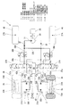
前記車体2側にはエンジン(駆動源の一例)25が設けられるとともに、このエンジン25には、1個の定容量形油圧ポンプ(油圧ポンプの一例)30が直接状に取り付けられている。そして、2個の油圧モータ21A,21Bに1個の定容量形油圧ポンプ30が対応されるように、すなわち、1ポンプ2モータタイプの油圧駆動システム(HSTシステム)になるように、定容量形油圧ポンプ30におけるポート31からの主供給配管32が、それぞれ分岐供給配管(油圧ホースなど)32A,32Bと比例電磁切換弁(コントロールバルブ)37A,37Bと給排配管(油圧ホースなど)33A,33B、34A,34Bとを介して、油圧モータ21A,21Bにおける両ポート35A,35B、36A,36Bに接続されている。39は吐き出し配管を示す。
An engine (an example of a drive source) 25 is provided on the
ここで比例電磁切換弁37A,37Bは、それぞれ油圧モータ21A,21Bの正逆回転と停止とを切り換えるために介在されている。そして、油圧ポンプ30からそれぞれの比例電磁切換弁37A,37Bへの分岐供給配管32A,32B中には、対応する前車輪3A,3Bのスリップ状検出により流量を絞る比例電磁絞り弁(比例電磁弁の一例)38A,38Bが介在されている。ここで比例電磁切換弁37A,37Bへの切換信号37a,37b、ならびに比例電磁絞り弁38A,38Bへの制御信号38a,38bは、コントローラ40から出すように構成されている。
Here, the proportional
すなわちコントローラ40には、運転席5に設けられた前後進切り換えレバー(チェンジレバー)50により操作される前後進切り換えスイッチ41からの前後進切り換え信号41aと、ハンドル16に設けた操舵輪切れ角センサ42からの切れ角信号42aと、両前車輪3A,3Bに対応して設けられた回転センサ43A,43Bからの回転数信号43a,43bと、電気式のアクセルペダル51からの車速指令信号51aと、電気式のブレーキペダル52からのブレーキ信号52aとが入力されるように構成されている。
That is, the
そして、ハンドル16で制御される左右の前車輪3A,3Bの回転差以上の差が生じたらスリップ状と見なし、その検出に基づいてコントローラ40から各比例電磁絞り弁38A,38Bへ出力される制御信号38a,38bにより、ハンドル切れ角で決められた所定の回転数よりも回転数の多い側の比例電磁絞り弁38A,38Bを操作して流量を絞るように構成されている。さらに、コントローラ40から各比例電磁切換弁37A,37Bへ出力される切換信号37a,37bにより、各前車輪3A,3Bの回転差と正逆転と停止とを制御するように構成されている。なお左右一対の後車輪4A,4Bは、それぞれ車体2に対して縦軸心27A,27Bの周りに旋回自在に設けられている。
Then, if a difference greater than the rotation difference between the left and right
以下に、上記した実施の形態1における作用を説明する。
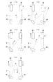
図1、図2、ならびに図5の(a)は通常の前進走行時を示している。このとき左右の前車輪3A,3Bならびに左右の後車輪4A,4Bは前後方向に向いている。また両比例電磁切換弁37A,37Bは一方オン(励磁)で正転連通状態にあり、そして比例電磁絞り弁38A,38Bは通常の連通状態にある。
Hereinafter, the operation in the first embodiment will be described.
1, 2, and 5 (a) show a normal forward travel time. At this time, the left and right
このようなフォークリフト1は、運転席5の座席15に座った作業者がハンドル16を操縦することで走行動し得る。その際に前後進走行は前後進切り換えレバー50で行い、その操作による前後進切り換えスイッチ41からの前後進切り換え信号41aをコントローラ40に入れ、このコントローラ40からの切換信号37a,37bにより各比例電磁切換弁37A,37Bを切り換え動させることにより、定容量形油圧ポンプ30からの作動油の流れの方向を切り換え、油圧モータ21A,21Bの回転方向を変える。
Such a
すなわち、両比例電磁切換弁37A,37Bが一方オンの状態にある図1においては、ポート31からの作動油を、主供給配管32、分岐供給配管32A,32B、比例電磁絞り弁38A,38B、比例電磁切換弁37A,37B、給排配管33A,33Bを介してポート35A,35Bに供給することで、油圧モータ21A,21Bを介して前車輪3A,3Bを正回転させて前進走行時とし得る。また、両比例電磁切換弁37A,37Bが他方オンの状態にある図3においては、ポート31からの作動油を、主供給配管32、分岐供給配管32A,32B、比例電磁絞り弁38A,38B、比例電磁切換弁37A,37B、給排配管34A,34Bを介してポート36A,36Bに供給することで、油圧モータ21A,21Bを介して前車輪3A,3Bを逆回転させて後進走行時とし得る。
That is, in FIG. 1 in which both proportional
さらに、アクセルペダル51にて車速指令信号51aをコントローラ40に入れることで、エンジン25の回転数、すなわち定容量形油圧ポンプ30からの油圧(作動油の流量)を制御し、以て油圧モータ21A,21Bの回転数を変えてスピードのコントロールを行う。なお停止などは、ブレーキペダル52によりブレーキ信号52aをコントローラ40に入れることで行える。
Further, by inputting the vehicle
旋回のコントロールは、運転席5の座席15に座った作業者がハンドル16を操作することで行い、その際に走行速度の変更は、ハンドル16の切れ角(回転角)による操舵輪切れ角センサ42からの切れ角信号42aをコントローラ40に入れ、このコントローラ40からの切換信号37a,37bにより各比例電磁切換弁37A,37Bを切り換え制御し、油圧モータ21A,21Bの回転数や回転方向を制御することで行える。つまり、以下のように、ハンドル16の切れ角に応じて両油圧モータ21A,21Bの回転数や回転方向を制御することで行える。
The turning control is performed by the operator sitting on the
すなわち、ハンドル16がニュートラルの場合、前述した図1のように、両比例電磁切換弁37A,37Bが一方オンの状態にあることから、図5の(a)に示されるように、左右の油圧モータ21A,21Bの回転数は同じとなり、直進を行う。
That is, when the
そしてハンドル切れ角が小さい場合、コントローラ40に入る切れ角信号42aに基づいて、コントローラ40から旋回内側の比例電磁切換弁37Bに出された切換信号37bにより、この比例電磁切換弁37Bを絞り制御して旋回内側の油圧モータ21Bを低速回転させる。これにより図5の(b)に示されるように、左右同方向の回転で、旋回内側の前車輪3Bを低速回転させ、以て左右の回転数に差を持たせることで旋回走行を行える。
When the steering wheel turning angle is small, the proportional
またハンドル切れ角が中間の場合、コントローラ40に入る切れ角信号42aに基づいて、コントローラ40から旋回内側の比例電磁切換弁37Bへの切換信号37bが停止されて、この比例電磁切換弁37Bはオフ(非励磁)で連通停止状態になり、以て旋回内側の油圧モータ21Bの回転を止める。これにより図5の(c)に示されるように、旋回外側の前車輪3Aのみ回転させ、以てピボット走行を行える。
When the steering wheel turning angle is intermediate, the
そしてハンドル切れ角が中間よりも大きい場合、コントローラ40に入る切れ角信号42aに基づいて、コントローラ40から旋回内側の比例電磁切換弁37Bに出された切換信号37bにより、この比例電磁切換弁37Bを、他方オンの状態に切り換えるとともに絞り制御し、以て旋回内側の油圧モータ21Bを低速逆回転させる。これにより図5の(d)に示されるように、左右逆方向の回転で、旋回内側の前車輪3Bを低速回転させ、以てピボット走行を行える。
When the steering angle is larger than the middle, the proportional
さらにハンドル切れ角が最大(ハンドルロック)の場合、コントローラ40に入る切れ角信号42aに基づいて、コントローラ40から旋回内側の比例電磁切換弁37Bに出された切換信号37bにより、この比例電磁切換弁37Bを他方オンの状態に切り換え制御し、以て旋回内側の油圧モータ21Bを逆回転させる。これにより図5の(e)に示されるように、左右の油圧モータ21A,21B、すなわち両前車輪3A,3Bは左右逆方向の回転で回転数は同じとなり、以て旋回半径を極小化したスピンターンを行える。
Further, when the steering angle is maximum (handle lock), the proportional electromagnetic switching valve is output from the
上記において、図5の(b)〜図5の(e)は右旋回の場合を示しているが、ハンドル16の切れ方向を逆にすることで、左旋回も同様に行われるものである。また前進の場合を示しているが、図3の状態で、後進の場合も同様に行われるものである。そして左右の旋回の際に、旋回キャスタ形式である左右の後車輪4A,4Bは追従換向される。
5 (b) to FIG. 5 (e) show the case of a right turn, the left turn is similarly performed by reversing the cutting direction of the
前述したような通常走行時などにおいて、左右一対の前車輪3A,3Bのうち、一方の前車輪、たとえば右側の前車輪3Bが軟弱地上に、そして他方の左側の前車輪3Aが乾燥地上にある場合、軟弱地上の前車輪3Bが空転状態となって、乾燥地上の前車輪3Aに駆動力が発生しなくなる。このとき、両回転センサ43A,43Bからの回転数信号43a,43bがコントローラ40において比較され、ハンドル16で制御される左右の前車輪3A,3Bの回転差以上の差が生じたらスリップ状と見なして検出される。
During normal running as described above, of the pair of left and right
すると、この検出に基づいて、ハンドル切れ角で決められた所定の回転数よりも回転数の多い側の比例電磁絞り弁、すなわち、軟弱地上の前車輪3Bに対応する比例電磁絞り弁38Bに制御信号38bが出され、この比例電磁絞り弁38Bを絞り操作する。
Then, based on this detection, the proportional
これにより、軟弱地上の前車輪3Bに対応する油圧モータ12Bへの作動油供給量を低減して、空転していた右側の後車輪11Bを低速回転させるとともに、乾燥地上の前車輪3Aに対応する油圧モータ12Aへの作動油供給量を増加することになる。したがって、乾燥地上の前車輪3Aに対応する油圧モータ12Aでは作動油の圧力が上昇することになり、以て乾燥地上の前車輪3Aを大きい駆動力で回転させて走行可能とし、軟弱地に入り込んだ状態から脱出し得る。
As a result, the amount of hydraulic oil supplied to the hydraulic motor 12B corresponding to the
なお、左側の前車輪3Aが軟弱地などで空転などしたときには、左側の前車輪3Aに対応する比例電磁絞り弁38Aに制御信号38aが出され、この比例電磁絞り弁38Aを絞り操作することで、上述と同様に作用し得る。
When the
これらのことにより、通常の配管中に比例電磁絞り弁38A,38Bを介在した簡単かつ安価な構成でありながら、常に脱出に十分な駆動力を得られることになる。しかも比例電磁絞り弁38A,38Bを、スリップ状の検出によりコントローラ40を介して自動的に制御し得ることで、流量を的確かつ確実に絞り制御し得る。
As a result, it is possible to always obtain a sufficient driving force for escape while having a simple and inexpensive configuration in which proportional
このようなフォークリフト1は、運転席5の座席15に座った作業者が、たとえば、リフト用レバーを操作しリフトシリンダー11を作動させることで、リフトブラケット12などを介してフォーク13をマスト6に沿って昇降動させ得、以て所期のフォーク作業を行える。またティルト用レバーを操作しティルトシリンダー8を作動させることで、マスト6を連結軸7の周りで回動(傾倒)させ得、以てリフトブラケット12などを介してフォーク13の姿勢を変化させ得る。
[実施の形態2]
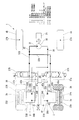
次に、本発明の実施の形態2を、図6に基づいて説明する。
In such a
[Embodiment 2]
Next, a second embodiment of the present invention will be described with reference to FIG.
上述した実施の形態1から比例電磁絞り弁38A,38Bを除去した構成とされている。この実施の形態2によると、通常走行時などにおいて、左右一対の前車輪3A,3Bのうち、一方の前車輪、たとえば右側の前車輪3Bが軟弱地上に、そして他方の左側の前車輪3Aが乾燥地上にある場合、軟弱地上の前車輪3Bが空転状態となって、乾燥地上の前車輪3Aに駆動力が発生しなくなる。このとき、両回転センサ43A,43Bからの回転数信号43a,43bがコントローラ40において比較され、ハンドル16で制御される左右の前車輪3A,3Bの回転差以上の差が生じたらスリップ状と見なして検出される。
The proportional
すると、この検出に基づいて、ハンドル切れ角で決められた所定の回転数よりも回転数の多い側の比例電磁切換弁、すなわち、軟弱地上の前車輪3Bに対応する比例電磁切換弁37Bに制御信号37bが出され、この比例電磁切換弁37Bを絞り操作する。
Then, based on this detection, control is performed to the proportional
これにより、軟弱地上の前車輪3Bに対応する油圧モータ12Bへの作動油供給量を低減して、空転していた右側の後車輪11Bを低速回転させるとともに、乾燥地上の前車輪3Aに対応する油圧モータ12Aへの作動油供給量を増加することになる。したがって、乾燥地上の前車輪3Aに対応する油圧モータ12Aでは作動油の圧力が上昇することになり、以て乾燥地上の前車輪3Aを大きい駆動力で回転させて走行可能とし、軟弱地に入り込んだ状態から脱出し得る。
As a result, the amount of hydraulic oil supplied to the hydraulic motor 12B corresponding to the
なお、左側の前車輪3Aが軟弱地などで空転などしたときには、左側の前車輪3Aに対応する比例電磁切換弁37Aに制御信号37aが出され、この比例電磁切換弁37Aを絞り操作することで、上述と同様に作用し得る。
When the
これらのことにより、通常の配管中に介在される油圧モータ21A,21Bの正逆回転を切り換えるための弁を比例電磁切換弁37A,37Bに入れ替えた簡単かつ安価な構成でありながら、常に脱出に十分な駆動力を得られることになる。しかも比例電磁切換弁37A,37Bを、スリップ状の検出によりコントローラ40を介して自動的に制御し得ることで、流量を的確かつ確実に絞り制御し得る。
As a result, the valve for switching the forward / reverse rotation of the
上記した実施の形態1、2では、左右一対の前車輪3A,3Bと左右一対の後車輪4A,4Bとからなる前後に2組の形式(4輪形式)が示されているが、これは左右一対でかつ前後多数組の車輪が設けられた形式の大型の走行台車などであってもよい。この場合には、全ての組が駆動車輪に構成されても、実施の形態1、2の要領で一部の組が駆動車輪に構成されてもよい。
In the first and second embodiments described above, two sets (four-wheel type) are shown before and after the pair of left and right
上記した実施の形態1では、比例電磁弁として比例電磁絞り弁38A,38Bが使用されているが、これは比例電磁流量調整弁などであってもよい。
上記した実施の形態1、2では、産業用車両としてカウンタータイプのフォークリフト1が示されているが、これは横行システムを持った産業用車両(フォークリフト)であってもよい。この場合には、油圧ポンプとして可変容量形油圧ポンプなどが使用される。
In the first embodiment described above, the proportional
In the first and second embodiments described above, the
上記した実施の形態1、2では、左右一対の後車輪4A,4Bとして、追従換向される旋回キャスタ形式が採用されているが、これは左右一対の後車輪4A,4Bのうち、一方の後車輪4をハンドルホイールによりシリンダーなどによって強制的に換向させるステア形式、他方の後車輪4を旋回キャスタ形式としてもよい。
In the above-described first and second embodiments, the pair of left and right
上記した実施の形態1、2では、定容量形油圧ポンプ30の駆動源としてエンジン25が示されているが、これは電動モータなどであってもよい。
上記した実施の形態1、2では、旋回時の走行速度の変更が、ハンドル16の切れ角に応じて油圧モータ21A,21Bの回転数を制御して行われているが、たとえば旋回時の走行速度は、ハンドル16の切れ角に関係なく、アクセルペダル51により油圧モータ21A,21Bの回転数を制御して行ってもよい。
In the first and second embodiments described above, the
In the first and second embodiments described above, the travel speed at the time of turning is changed by controlling the rotational speeds of the
上記した実施の形態1、2では、産業用車両としてカウンタータイプのフォークリフト1が示されているが、産業用車両としては、大型の運搬車、ローダ、サイドフォークリフトなどであっても同様に作用し得るものである。
In the above-described first and second embodiments, the
1 フォークリフト(産業用車両)
2 車体
3A 前車輪(駆動車輪)
3B 前車輪(駆動車輪)
4A 後車輪
4B 後車輪
13 フォーク
16 ハンドル
21A 油圧モータ
21B 油圧モータ
25 エンジン(駆動源)
30 定容量形油圧ポンプ(油圧ポンプ)
32 主供給配管
32A 分岐供給配管
32B 分岐供給配管
33A 給排配管
33B 給排配管
34A 給排配管
34B 給排配管
37A 比例電磁切換弁
37a 切換信号
37B 比例電磁切換弁
37b 切換信号
38A 比例電磁絞り弁(比例電磁弁)
38a 制御信号
38B 比例電磁絞り弁(比例電磁弁)
38b 制御信号
40 コントローラ
41 前後進切り換えスイッチ
41a 前後進切り換え信号
42 操舵輪切れ角センサ
42a 切れ角信号
43A 回転センサ
43a 回転数信号
43B 回転センサ
43b 回転数信号
50 前後進切り換えレバー
51 アクセルペダル
51a 車速指令信号
52 ブレーキペダル
52a ブレーキ信号
1 Forklift (industrial vehicle)
2
3B Front wheel (drive wheel)
30 Constant displacement hydraulic pump (hydraulic pump)
32 Main supply piping 32A
38a Control signal 38B Proportional solenoid throttle valve (proportional solenoid valve)
Claims (4)
4. The hydraulic drive type industrial vehicle according to claim 2, wherein the proportional solenoid valve is a proportional solenoid throttle valve.
Priority Applications (1)
| Application Number | Priority Date | Filing Date | Title |
|---|---|---|---|
| JP2004061489A JP2005247162A (en) | 2004-03-05 | 2004-03-05 | Hydraulic drive type industrial vehicle |
Applications Claiming Priority (1)
| Application Number | Priority Date | Filing Date | Title |
|---|---|---|---|
| JP2004061489A JP2005247162A (en) | 2004-03-05 | 2004-03-05 | Hydraulic drive type industrial vehicle |
Publications (1)
| Publication Number | Publication Date |
|---|---|
| JP2005247162A true JP2005247162A (en) | 2005-09-15 |
Family
ID=35028069
Family Applications (1)
| Application Number | Title | Priority Date | Filing Date |
|---|---|---|---|
| JP2004061489A Pending JP2005247162A (en) | 2004-03-05 | 2004-03-05 | Hydraulic drive type industrial vehicle |
Country Status (1)
| Country | Link |
|---|---|
| JP (1) | JP2005247162A (en) |
Cited By (3)
| Publication number | Priority date | Publication date | Assignee | Title |
|---|---|---|---|---|
| JP2007177983A (en) * | 2005-12-28 | 2007-07-12 | Toyota Motor Corp | Drive device |
| JP2010058693A (en) * | 2008-09-04 | 2010-03-18 | Toyota Industries Corp | Fuel cell powered vehicle |
| WO2016028469A1 (en) * | 2014-08-21 | 2016-02-25 | Caterpillar Paving Products Inc. | Use of wheel slip to help identify soft spots |
-
2004
- 2004-03-05 JP JP2004061489A patent/JP2005247162A/en active Pending
Cited By (5)
| Publication number | Priority date | Publication date | Assignee | Title |
|---|---|---|---|---|
| JP2007177983A (en) * | 2005-12-28 | 2007-07-12 | Toyota Motor Corp | Drive device |
| JP4618124B2 (en) * | 2005-12-28 | 2011-01-26 | トヨタ自動車株式会社 | Drive device |
| JP2010058693A (en) * | 2008-09-04 | 2010-03-18 | Toyota Industries Corp | Fuel cell powered vehicle |
| WO2016028469A1 (en) * | 2014-08-21 | 2016-02-25 | Caterpillar Paving Products Inc. | Use of wheel slip to help identify soft spots |
| US10113929B2 (en) | 2014-08-21 | 2018-10-30 | Caterpillar Paving Products Inc. | Use of wheel slip to help identify soft spots |
Similar Documents
| Publication | Publication Date | Title |
|---|---|---|
| AU2008253242B2 (en) | Three-wheel forklift truck | |
| US6793036B1 (en) | Working vehicle with transverse system | |
| JP2000142145A (en) | Four-wheel drive car for industrial use and hydraulic drive device for it | |
| JP2001001918A (en) | Hydraulic power steering device | |
| JP2005247162A (en) | Hydraulic drive type industrial vehicle | |
| JP2005255064A (en) | Industrial vehicle of hydraulic drive type | |
| JP2021177100A (en) | Hydraulic system of working machine | |
| JP2000318995A (en) | Hydraulically driven forklift | |
| JP7290619B2 (en) | work vehicle | |
| JP3441772B2 (en) | Hydraulic excavator travel restriction device | |
| WO2001064575A1 (en) | Hydraulic-driven working vehicle | |
| JPS621792Y2 (en) | ||
| JP2006232142A (en) | Turning control device of working vehicle | |
| JP2002362889A (en) | Working vehicle with traverse system | |
| JP2547724Y2 (en) | Work vehicle vehicle drive | |
| KR100660981B1 (en) | Hydraulically operated fork lift | |
| JP3249105B2 (en) | Work vehicle with traversing system | |
| JP4518316B2 (en) | Industrial vehicle steering device | |
| JP2022033105A (en) | Work machine | |
| JP4687237B2 (en) | Industrial vehicle cargo handling control device | |
| JP5016560B2 (en) | Work vehicle traveling device | |
| JP2021025273A (en) | Work machine | |
| JP2001090706A (en) | Device for changing combination of operating device and actuator | |
| JP2012219578A (en) | Travel operation device for construction machine | |
| JP2006341732A (en) | Wheel type construction machine |
Legal Events
| Date | Code | Title | Description |
|---|---|---|---|
| A621 | Written request for application examination |
Free format text: JAPANESE INTERMEDIATE CODE: A621 Effective date: 20060927 |
|
| RD04 | Notification of resignation of power of attorney |
Free format text: JAPANESE INTERMEDIATE CODE: A7424 Effective date: 20080430 |
|
| A977 | Report on retrieval |
Free format text: JAPANESE INTERMEDIATE CODE: A971007 Effective date: 20081112 |
|
| A131 | Notification of reasons for refusal |
Effective date: 20081118 Free format text: JAPANESE INTERMEDIATE CODE: A131 |
|
| A02 | Decision of refusal |
Free format text: JAPANESE INTERMEDIATE CODE: A02 Effective date: 20090407 |