JP2005241237A - Condenser and heat exchanger - Google Patents
Condenser and heat exchanger Download PDFInfo
- Publication number
- JP2005241237A JP2005241237A JP2005011090A JP2005011090A JP2005241237A JP 2005241237 A JP2005241237 A JP 2005241237A JP 2005011090 A JP2005011090 A JP 2005011090A JP 2005011090 A JP2005011090 A JP 2005011090A JP 2005241237 A JP2005241237 A JP 2005241237A
- Authority
- JP
- Japan
- Prior art keywords
- refrigerant
- header
- inlet
- condenser
- headers
- Prior art date
- Legal status (The legal status is an assumption and is not a legal conclusion. Google has not performed a legal analysis and makes no representation as to the accuracy of the status listed.)
- Pending
Links
- 239000003507 refrigerant Substances 0.000 claims abstract description 306
- 239000010687 lubricating oil Substances 0.000 claims abstract description 19
- 238000004781 supercooling Methods 0.000 claims description 42
- 238000005192 partition Methods 0.000 claims description 24
- 238000005057 refrigeration Methods 0.000 claims description 16
- 239000012530 fluid Substances 0.000 claims description 7
- 239000002826 coolant Substances 0.000 claims description 5
- 230000005494 condensation Effects 0.000 description 22
- 238000009833 condensation Methods 0.000 description 22
- XAGFODPZIPBFFR-UHFFFAOYSA-N aluminium Chemical compound [Al] XAGFODPZIPBFFR-UHFFFAOYSA-N 0.000 description 15
- 229910052782 aluminium Inorganic materials 0.000 description 15
- 230000000694 effects Effects 0.000 description 7
- 230000000052 comparative effect Effects 0.000 description 6
- 230000007423 decrease Effects 0.000 description 6
- 239000007788 liquid Substances 0.000 description 4
- 238000012360 testing method Methods 0.000 description 3
- 230000006866 deterioration Effects 0.000 description 2
- 238000003780 insertion Methods 0.000 description 2
- 230000037431 insertion Effects 0.000 description 2
- 239000000126 substance Substances 0.000 description 2
- 229910000838 Al alloy Inorganic materials 0.000 description 1
- 230000003247 decreasing effect Effects 0.000 description 1
- 238000011156 evaluation Methods 0.000 description 1
- 238000002474 experimental method Methods 0.000 description 1
- 239000000314 lubricant Substances 0.000 description 1
- 238000005461 lubrication Methods 0.000 description 1
- 230000002093 peripheral effect Effects 0.000 description 1
- 238000011160 research Methods 0.000 description 1
- 238000000638 solvent extraction Methods 0.000 description 1
Images


Classifications
-
- F—MECHANICAL ENGINEERING; LIGHTING; HEATING; WEAPONS; BLASTING
- F25—REFRIGERATION OR COOLING; COMBINED HEATING AND REFRIGERATION SYSTEMS; HEAT PUMP SYSTEMS; MANUFACTURE OR STORAGE OF ICE; LIQUEFACTION SOLIDIFICATION OF GASES
- F25B—REFRIGERATION MACHINES, PLANTS OR SYSTEMS; COMBINED HEATING AND REFRIGERATION SYSTEMS; HEAT PUMP SYSTEMS
- F25B2339/00—Details of evaporators; Details of condensers
- F25B2339/04—Details of condensers
- F25B2339/044—Condensers with an integrated receiver
-
- F—MECHANICAL ENGINEERING; LIGHTING; HEATING; WEAPONS; BLASTING
- F25—REFRIGERATION OR COOLING; COMBINED HEATING AND REFRIGERATION SYSTEMS; HEAT PUMP SYSTEMS; MANUFACTURE OR STORAGE OF ICE; LIQUEFACTION SOLIDIFICATION OF GASES
- F25B—REFRIGERATION MACHINES, PLANTS OR SYSTEMS; COMBINED HEATING AND REFRIGERATION SYSTEMS; HEAT PUMP SYSTEMS
- F25B40/00—Subcoolers, desuperheaters or superheaters
- F25B40/02—Subcoolers
Landscapes
- Heat-Exchange Devices With Radiators And Conduit Assemblies (AREA)
Abstract
Description
この発明は、たとえば自動車に搭載される冷凍サイクルであるカーエアコンに使用される凝縮器および熱交換器に関する。 The present invention relates to a condenser and a heat exchanger used in, for example, a car air conditioner that is a refrigeration cycle mounted on an automobile.
この明細書および特許請求の範囲において、各図面の上下、左右をそれぞれ上下、左右というものとする。 In the present specification and claims, the upper and lower sides and the left and right sides of each drawing are respectively referred to as the upper and lower sides and the left and right sides.
カーエアコンを構成する冷凍サイクルは、圧縮機、凝縮器、減圧器(膨張弁)および蒸発器を有しており、圧縮機により圧縮された高温高圧のガス状冷媒が凝縮器により凝縮されて液状冷媒となり、液状冷媒が膨張弁により減圧膨張させられた後、蒸発器で蒸発させられるようになっている。また、近年、冷凍サイクルの高効率化を図るために、凝縮器で凝縮された液状冷媒を、さらに凝縮温度よりも5〜15℃程度低い温度まで過冷却する過冷却器が用いられるようになってきている。 The refrigeration cycle that constitutes a car air conditioner has a compressor, a condenser, a decompressor (expansion valve), and an evaporator. The high-temperature and high-pressure gaseous refrigerant compressed by the compressor is condensed by the condenser to be liquid. It becomes a refrigerant, and after the liquid refrigerant is decompressed and expanded by the expansion valve, it is evaporated by the evaporator. In recent years, in order to increase the efficiency of the refrigeration cycle, a supercooler that supercools the liquid refrigerant condensed in the condenser to a temperature lower by about 5 to 15 ° C. than the condensation temperature has come to be used. It is coming.
従来、凝縮器としては、互いに間隔をおいて配置された上下方向にのびる1対のヘッダと、両ヘッダ間に上下方向に間隔をおいて並列状に配置されかつ両端部が両ヘッダにそれぞれ接続された複数の偏平状冷媒流通管と、隣接する冷媒流通管間に配置されたフィンとを備えており、一方のヘッダに、その内部に冷媒を流入させる冷媒入口が形成されるとともに、他方のヘッダに、その内部から冷媒を流出させる冷媒出口が形成され、冷媒入口から一方のヘッダに流入した冷媒が全ての冷媒流通管を他方のヘッダ側に流れるようになっているものが知られている(たとえば、特許文献1参照)。なお、特許文献1に記載されているのは、上述した凝縮器からなる凝縮部の下方に、互いに間隔をおいて配置された上下方向にのびる1対のヘッダと、両ヘッダ間に上下方向に間隔をおいて並列状に配置されかつ両端部が両ヘッダにそれぞれ接続された複数の偏平状冷媒流通管と、隣接する冷媒流通管間に配置されたフィンとを備えた過冷却部が配置されており、凝縮部の両ヘッダに、仕切りを介して過冷却部の両ヘッダが設けられ、凝縮部における冷媒出口が形成されたヘッダと、このヘッダに連結された過冷却部のヘッダにまたがるようにレシーバタンクが取り付けられ、凝縮部の冷媒出口から流出した冷媒がレシーバタンクを通過して過冷却部のヘッダに流入するようになっている熱交換器である。 Conventionally, as a condenser, a pair of headers that are vertically spaced apart from each other and a pair of headers that are spaced in parallel in the vertical direction between both headers, and both end portions are connected to both headers, respectively. A plurality of flat refrigerant flow pipes and fins arranged between adjacent refrigerant flow pipes, and one header is formed with a refrigerant inlet through which the refrigerant flows into the other header. It is known that a refrigerant outlet for allowing a refrigerant to flow out from the inside of the header is formed in the header so that the refrigerant flowing into one header from the refrigerant inlet flows through all the refrigerant flow pipes to the other header side. (For example, refer to Patent Document 1). Note that Patent Document 1 describes a pair of headers arranged in the vertical direction below the condensing unit composed of the above-described condenser and extending in the vertical direction between the headers. A supercooling section is provided that includes a plurality of flat refrigerant flow pipes arranged in parallel at intervals and having both ends connected to both headers, and fins arranged between adjacent refrigerant flow pipes. Both headers of the supercooling unit are provided on both headers of the condensing unit via a partition, and straddle the header in which the refrigerant outlet in the condensing unit is formed and the header of the supercooling unit connected to the header. The refrigerant tank which is attached to the receiver tank and flows out from the refrigerant outlet of the condensing part passes through the receiver tank and flows into the header of the supercooling part.
ところで、冷凍サイクルの圧縮機としては、通常、摺動部の潤滑のために潤滑油を使用しており、そのため冷媒中には3〜10質量%程度の圧縮機潤滑油が必然的に混入している。そして、冷媒中に圧縮機潤滑油が混入していると、凝縮器の凝縮性能が低下し、冷凍サイクルの冷凍効率が低下するという問題がある。特に、特許文献1に記載されているような、互いに間隔をおいて配置された上下方向にのびる1対のヘッダと、両ヘッダ間に上下方向に間隔をおいて並列状に配置されかつ両端部が両ヘッダにそれぞれ接続された複数の偏平状冷媒流通管と、隣接する冷媒流通管間に配置されたフィンとを備えており、一方のヘッダに、その内部に冷媒を流入させる冷媒入口が形成されるとともに、他方のヘッダに、その内部から冷媒を流出させる冷媒出口が形成され、冷媒入口から一方のヘッダに流入した冷媒が全ての冷媒流通管を他方のヘッダ側に流れるようになっているタイプの凝縮器の場合に、上述した凝縮性能の低下は顕著であるという問題がある。
この発明の目的は、上記問題を解決し、冷媒中に圧縮機潤滑油が混入している場合における凝縮性能の低下を防止しうる凝縮器を提供することにある。 An object of the present invention is to provide a condenser that solves the above-described problems and can prevent a decrease in condensation performance when compressor lubricating oil is mixed in the refrigerant.
本発明者は、上記課題を解決すべく種々実験、研究を重ねた結果、特許文献1記載の凝縮器においては、冷媒入口の上下方向の中心よりも下方に存在する冷媒流通管の本数が、冷媒に圧縮機潤滑油が混入している場合の凝縮性能の低下に影響を及ぼすことを見出した。すなわち、この本数が多過ぎると圧縮機潤滑油が入口ヘッダの下方に沈降して主に下部に位置する冷媒流通管内を流れ、その結果下部に位置する冷媒流通管内を流れる冷媒量が少なくなって、凝縮に寄与する冷媒流通管の数が少なくなることを見出した。 As a result of repeated various experiments and researches to solve the above problems, the inventor has found that the number of refrigerant flow pipes existing below the center in the vertical direction of the refrigerant inlet in the condenser described in Patent Document 1, It has been found that it affects the reduction of condensation performance when compressor lubricant is mixed in the refrigerant. That is, if the number is too large, the compressor lubricating oil settles below the inlet header and flows mainly in the refrigerant flow pipe located at the lower part, and as a result, the amount of refrigerant flowing in the refrigerant flow pipe located at the lower part decreases. It has been found that the number of refrigerant flow pipes contributing to condensation is reduced.
この発明は、このような知見に基づいて完成されたものであり、以下の態様よりなる。 The present invention has been completed based on such knowledge and comprises the following aspects.
1)左右方向に間隔をおいて配置された上下方向にのびる入口ヘッダおよび出口ヘッダと、両ヘッダ間に上下方向に間隔をおいて並列状に配置されかつ両端部が両ヘッダにそれぞれ接続された複数の偏平状冷媒流通管と、隣接する冷媒流通管間に配置されたフィンとを備えており、入口ヘッダに、その内部に冷媒を流入させる冷媒入口が形成されるとともに、出口ヘッダに、その内部から冷媒を流出させる冷媒出口が形成され、冷媒入口から入口ヘッダに流入した冷媒が全ての冷媒流通管内を出口ヘッダ側に流れるようになっている凝縮器であって、冷媒入口の上下方向の中心よりも下方に存在する冷媒流通管の本数が21本以下である凝縮器。 1) Vertically extending inlet and outlet headers spaced apart in the left-right direction, and both headers arranged in parallel with vertical spacing between both headers, and both ends connected to both headers. A plurality of flat refrigerant flow pipes and fins disposed between adjacent refrigerant flow pipes are provided, and an inlet header is formed with a refrigerant inlet for allowing the refrigerant to flow therein, and an outlet header A condenser outlet is formed in which a refrigerant outlet for allowing the refrigerant to flow out from the inside is formed, and the refrigerant flowing into the inlet header from the refrigerant inlet flows through all the refrigerant flow pipes toward the outlet header side, and is arranged in the vertical direction of the refrigerant inlet. A condenser in which the number of refrigerant flow pipes existing below the center is 21 or less.
2)冷媒入口の上下方向の中心よりも下方に存在する冷媒流通管の本数が16本以下である上記1)記載の凝縮器。 2) The condenser according to 1) above, wherein the number of refrigerant circulation pipes existing below the center of the refrigerant inlet in the vertical direction is 16 or less.
3)冷媒入口の上下方向の中心よりも下方に存在する冷媒流通管の本数が7本以下である上記1)記載の凝縮器。 3) The condenser according to 1) above, wherein the number of refrigerant circulation pipes existing below the center of the refrigerant inlet in the vertical direction is 7 or less.
4)冷媒流通管の総本数が22〜70本である上記1)〜3)のうちのいずれかに記載の凝縮器。 4) The condenser according to any one of 1) to 3) above, wherein the total number of refrigerant circulation pipes is 22 to 70.
5)正面から見た高さが150〜500mm、左右方向の幅が200〜800mm、冷媒流通管の高さが0.8〜3mm、隣接する冷媒流通管間の間隔が4.5〜12mmである上記1)〜4)のうちのいずれかに記載の凝縮器。 5) The height viewed from the front is 150 to 500 mm, the width in the left-right direction is 200 to 800 mm, the height of the refrigerant flow pipe is 0.8 to 3 mm, and the interval between adjacent refrigerant flow pipes is 4.5 to 12 mm. The condenser according to any one of 1) to 4) above.
6)左右方向に間隔をおいて配置された上下方向にのびる2つのヘッダと、両ヘッダ間に上下方向に間隔をおいて並列状に配置されかつ両端部が両ヘッダにそれぞれ接続された複数の偏平状冷媒流通管と、隣接する冷媒流通管間に配置されたフィンとを備えており、上下に連続して並んだ複数の冷媒流通管からなる通路群が上下方向に並んで複数設けられ、各通路群を構成する全ての冷媒流通管における冷媒の流れ方向が同一となっているとともに、隣り合う2つの通路群の冷媒流通管における冷媒の流れ方向が異なっており、一方のヘッダにおける上端の通路群と対応する高さ位置に、その内部に冷媒を流入させる冷媒入口が形成されるとともに、冷媒入口が形成された上記一方のヘッダまたは他方のヘッダにおける下端の通路群と対応する高さ位置に、その内部から冷媒を流出させる冷媒出口が形成され、冷媒入口から送り込まれた冷媒が、全ての通路群の冷媒流通管を通って冷媒出口から排出されるようになされている凝縮器であって、上端通路群における冷媒入口の上下方向の中心よりも下方に存在する冷媒流通管の本数が21本以下である凝縮器。 6) Two headers extending in the vertical direction spaced apart in the left-right direction, and a plurality of headers arranged in parallel with a space in the vertical direction between the headers and both ends connected to both headers. A flat refrigerant flow pipe, and fins disposed between adjacent refrigerant flow pipes, and a plurality of passage groups consisting of a plurality of refrigerant flow pipes arranged continuously in the vertical direction are provided in the vertical direction. The refrigerant flow directions in all the refrigerant flow pipes constituting each passage group are the same, and the refrigerant flow directions in the refrigerant flow pipes of the two adjacent passage groups are different. At the height corresponding to the passage group, a refrigerant inlet through which the refrigerant flows is formed, and corresponds to the lower end passage group in the one header or the other header in which the refrigerant inlet is formed. In this position, a refrigerant outlet for allowing the refrigerant to flow out from the inside is formed, and the refrigerant sent from the refrigerant inlet is discharged from the refrigerant outlet through the refrigerant flow pipes of all the passage groups. And the condenser whose number of the refrigerant | coolant circulation pipes which exist below the center of the up-down direction of the refrigerant | coolant inlet in an upper end channel group is 21 or less.
7)上端通路群における冷媒入口の上下方向の中心よりも下方に存在する冷媒流通管の本数が16本以下である上記6)記載の凝縮器。 7) The condenser according to 6) above, wherein the number of refrigerant flow pipes existing below the center of the refrigerant inlet in the upper end passage group is 16 or less.
8)上端通路群における冷媒入口の上下方向の中心よりも下方に存在する冷媒流通管の本数が7本以下である上記6)記載の凝縮器。 8) The condenser according to 6) above, wherein the number of refrigerant circulation pipes existing below the center of the refrigerant inlet in the upper end passage group is 7 or less.
9)上端通路群を構成する冷媒流通管の総本数が22〜70本である上記6)〜8)のうちのいずれかに記載の凝縮器。 9) The condenser according to any one of 6) to 8) above, wherein the total number of refrigerant circulation pipes constituting the upper end passage group is 22 to 70.
10)左右方向の幅が200〜800mm、冷媒流通管の高さが0.8〜3mm、隣接する冷媒流通管間の間隔が4.5〜12mmであり、上端通路群の正面から見た高さが150〜500mmである上記6)〜9)のうちのいずれかに記載の凝縮器。 10) The horizontal width is 200 to 800 mm, the height of the refrigerant flow pipe is 0.8 to 3 mm, the distance between adjacent refrigerant flow pipes is 4.5 to 12 mm, and the height seen from the front of the upper end passage group The condenser in any one of said 6) -9) whose length is 150-500 mm.
11)使用される冷媒に3〜10質量%の圧縮機潤滑油が混入している上記1)〜10)のうちのいずれかに記載の凝縮器。 11) The condenser according to any one of 1) to 10) above, wherein 3 to 10% by mass of compressor lubricating oil is mixed in the refrigerant used.
12)各冷媒流通管内に、複数の冷媒通路が並列状に設けられており、冷媒通路の流体直径が0.2〜1.6mmである上記1)〜11)のうちのいずれかに記載の凝縮器。 12) A plurality of refrigerant passages are provided in parallel in each refrigerant circulation pipe, and the fluid diameter of the refrigerant passages is 0.2 to 1.6 mm. Condenser.
13)上記1)〜5)のうちのいずれかに記載の凝縮器からなる凝縮部の下方に、左右方向に間隔をおいて配置された上下方向にのびる1対のヘッダと、両ヘッダ間に上下方向に間隔をおいて並列状に配置されかつ両端部が両ヘッダにそれぞれ接続された複数の偏平状冷媒流通管と、隣接する冷媒流通管間に配置されたフィンとを備えた過冷却部が配置され、凝縮部の出口ヘッダに仕切りを介して過冷却部の一方のヘッダが設けられるとともに、凝縮部の入口ヘッダに仕切りを介して過冷却部の他方のヘッダが設けられ、凝縮部の出口ヘッダと、過冷却部の一方のヘッダにまたがるようにレシーバタンクが取り付けられ、凝縮部の冷媒出口から流出した冷媒がレシーバタンクを通過して過冷却部の一方のヘッダに流入するようになっている熱交換器。。 13) A pair of headers extending in the up-down direction and spaced apart in the left-right direction below the condensing unit comprising the condenser according to any one of 1) to 5) above, and between both headers A supercooling section provided with a plurality of flat refrigerant flow pipes arranged in parallel at intervals in the vertical direction and having both ends connected to both headers, and fins arranged between adjacent refrigerant flow pipes Is disposed, and one header of the supercooling unit is provided via the partition at the outlet header of the condensing unit, and the other header of the supercooling unit is provided via the partition at the inlet header of the condensing unit, A receiver tank is attached so as to straddle the outlet header and one header of the supercooling unit, and the refrigerant flowing out from the refrigerant outlet of the condensing unit passes through the receiver tank and flows into one header of the supercooling unit. Heat exchanger. .
14)上記6)〜10)のうちのいずれかに記載の凝縮器からなる凝縮部の下方に、左右方向に間隔をおいて配置された上下方向にのびる1対のヘッダと、両ヘッダ間に上下方向に間隔をおいて並列状に配置されかつ両端部が両ヘッダにそれぞれ接続された複数の偏平状冷媒流通管と、隣接する冷媒流通管間に配置されたフィンとを備えた過冷却部が配置され、凝縮部における冷媒出口が形成された一方のヘッダに仕切りを介して過冷却部の一方のヘッダが設けられるとともに、凝縮部における他方のヘッダに仕切りを介して過冷却部の他方のヘッダが設けられ、凝縮部の冷媒出口が形成されたヘッダと、過冷却部の一方のヘッダにまたがるようにレシーバタンクが取り付けられ、凝縮部の冷媒出口から流出した冷媒がレシーバタンクを通過して過冷却部の一方のヘッダに流入するようになっている熱交換器。 14) A pair of vertically extending headers arranged at intervals in the left-right direction below the condensing unit comprising the condenser according to any one of 6) to 10) above, and between both headers A supercooling section provided with a plurality of flat refrigerant flow pipes arranged in parallel at intervals in the vertical direction and having both ends connected to both headers, and fins arranged between adjacent refrigerant flow pipes Is arranged, and one header of the supercooling unit is provided via a partition in one header where the refrigerant outlet in the condensing unit is formed, and the other header of the supercooling unit is provided via the partition in the other header of the condensing unit A header is provided and a receiver tank is attached so as to straddle the header in which the refrigerant outlet of the condensing part is formed and one header of the supercooling part, and the refrigerant flowing out from the refrigerant outlet of the condensing part passes through the receiver tank. Supercooling Heat exchanger adapted to flow into one of the headers of.
15)使用される冷媒に3〜10質量%の圧縮機潤滑油が混入している上記13)または14)記載の熱交換器。 15) The heat exchanger according to 13) or 14) above, wherein 3 to 10% by mass of compressor lubricating oil is mixed in the refrigerant used.
16)過冷却器の各冷媒流通管内に、複数の冷媒通路が並列状に設けられており、冷媒通路の流体直径が0.2〜1.6mmである上記13)〜15)のうちのいずれかに記載の熱交換器。 16) A plurality of refrigerant passages are provided in parallel in each refrigerant circulation pipe of the subcooler, and the fluid diameter of the refrigerant passage is 0.2 to 1.6 mm, any of the above 13) to 15) The heat exchanger according to crab.
17)圧縮機、上記1)〜12)のうちのいずれかに記載の凝縮器、膨張弁および蒸発器を有しており、3〜10質量%の圧縮機潤滑油が混入している冷媒が使用される冷凍サイクル。 17) A compressor, the condenser according to any one of the above 1) to 12), an expansion valve and an evaporator, and a refrigerant mixed with 3 to 10% by mass of compressor lubricating oil The refrigeration cycle used.
18)圧縮機、上記13)〜16)のうちのいずれかに記載の熱交換器、膨張弁および蒸発器を有しており、3〜10質量%の圧縮機潤滑油が混入している冷媒が使用される冷凍サイクル。 18) Compressor, refrigerant having the heat exchanger, expansion valve, and evaporator according to any one of the above 13) to 16), in which 3 to 10% by mass of compressor lubricating oil is mixed Refrigeration cycle used.
19)上記17)または18)記載の冷凍サイクルをエアコンとして備えている車両。 19) A vehicle equipped with the refrigeration cycle according to 17) or 18) as an air conditioner.
上記1)の凝縮器によれば、冷媒入口の上下方向の中心よりも下方に存在する冷媒流通管の本数が21本以下であるから、冷媒に圧縮機潤滑油が混入している場合にも、冷媒は下部に位置する冷媒流通管内にも流れ易くなり、凝縮に寄与する冷媒流通管の数が比較的多くなって凝縮性能の低下が抑制される。 According to the condenser of 1), since the number of refrigerant circulation pipes existing below the center of the refrigerant inlet in the vertical direction is 21 or less, even when compressor lubricating oil is mixed in the refrigerant, The refrigerant easily flows into the refrigerant flow pipe located in the lower part, and the number of refrigerant flow pipes contributing to condensation is relatively large, so that a reduction in condensation performance is suppressed.
上記2)の凝縮器によれば、凝縮性能の低下を抑制する効果が一層優れたものになる。 According to the condenser of 2) above, the effect of suppressing a decrease in condensation performance is further improved.
上記3)の凝縮器によれば、凝縮性能の低下を抑制する効果がさらに一層優れたものになる。 According to the condenser of 3) above, the effect of suppressing a decrease in condensation performance is further improved.
上記4)のように、冷媒流通管の総本数が22〜70本の場合に、上記1)〜3)の凝縮器は顕著な効果を奏する。 As in 4) above, when the total number of refrigerant circulation pipes is 22 to 70, the condensers 1) to 3) have a remarkable effect.
上記6)の凝縮器によれば、上端通路群における冷媒入口の上下方向の中心よりも下方に存在する冷媒流通管の本数が21本以下であるから、冷媒に圧縮機潤滑油が混入している場合にも、冷媒は上端通路群の下部に位置する冷媒流通管内にも流れ易くなり、凝縮に寄与する冷媒流通管の数が比較的多くなって上端通路群での凝縮性能の低下が抑制される。 According to the condenser 6), since the number of refrigerant flow pipes existing below the center of the refrigerant inlet in the upper end passage group is 21 or less, compressor lubricating oil is mixed into the refrigerant. Even when the refrigerant is present, the refrigerant easily flows into the refrigerant flow pipes located below the upper end passage group, and the number of refrigerant flow pipes contributing to condensation is relatively large, and the deterioration of the condensation performance in the upper end passage group is suppressed. Is done.
上記7)の凝縮器によれば、上端通路群での凝縮性能の低下を抑制する効果が一層優れたものになる。 According to the condenser of the above 7), the effect of suppressing a decrease in the condensation performance in the upper end passage group is further improved.
上記8)の凝縮器によれば、上端通路群での凝縮性能の低下を抑制する効果がさらに一層優れたものになる。 According to the condenser of the above 8), the effect of suppressing the deterioration of the condensation performance in the upper end passage group becomes even more excellent.
上記9)のように、上端通路群を構成する冷媒流通管の総本数が22〜70本の場合に、上記6)〜8)の凝縮器は顕著な効果を奏する。 As in 9) above, when the total number of refrigerant circulation pipes constituting the upper end passage group is 22 to 70, the condensers in 6) to 8) have a remarkable effect.
上記11)のように、冷媒に3〜10質量%の圧縮機潤滑油が混入している場合に、上記1)〜10)の凝縮器は顕著な効果を奏する。 As in the above 11), when 3 to 10% by mass of compressor lubricating oil is mixed in the refrigerant, the condensers 1) to 10) have a remarkable effect.
以下、この発明の実施形態を、図面を参照して説明する。なお、全図面を通じて同一部分および同一物には同一符号を付して重複する説明を省略する。 Embodiments of the present invention will be described below with reference to the drawings. In addition, the same code | symbol is attached | subjected to the same part and the same thing through all drawings, and the overlapping description is abbreviate | omitted.
この実施形態は、この発明を、凝縮部と過冷却部とが一体化された熱交換器に適用したものである。なお、以下の説明において、「アルミニウム」という語には、純アルミニウムの他にアルミニウム合金を含むものとする。 In this embodiment, the present invention is applied to a heat exchanger in which a condensing unit and a supercooling unit are integrated. In the following description, the term “aluminum” includes aluminum alloys in addition to pure aluminum.
図1はこの発明による凝縮器からなる凝縮部を備えた熱交換器の全体構成を示し、図2はその要部の構成を示す。 FIG. 1 shows the overall structure of a heat exchanger having a condensing part comprising a condenser according to the present invention, and FIG. 2 shows the structure of the main part thereof.
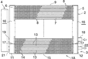
図1において、熱交換器(1)は、凝縮部(2)および過冷却部(3)が同一垂直面内において上下に並んで設けられ、凝縮部(2)および過冷却部(3)にまたがってレシーバタンク(4)が設けられたものである。 In FIG. 1, a heat exchanger (1) has a condensing part (2) and a supercooling part (3) arranged vertically in the same vertical plane, and the condensing part (2) and the supercooling part (3) A receiver tank (4) is provided across the board.
凝縮部(2)は、互いに間隔をおいて配置されかつ上下方向にのびるアルミニウム製入口ヘッダ(5)およびアルミニウム製出口ヘッダ(6)と、両ヘッダ(5)(6)間に上下方向に間隔をおいて並列状に配置されかつ両端部が両ヘッダ(5)(6)にそれぞれ接続された複数のアルミニウム製偏平状冷媒流通管(7)と、隣接する冷媒流通管(7)間に配置されて冷媒流通管(7)にろう付されたアルミニウム製コルゲートフィン(8)とを備えている。上端の冷媒流通管(7)の上方にはこの冷媒流通管(7)と間隔をおいてアルミニウム製サイドプレート(9)が配置され、サイドプレート(9)と冷媒流通管(7)との間にもアルミニウム製コルゲートフィン(8)が配置されてサイドプレート(9)および冷媒流通管(7)にろう付されている。 The condensing part (2) is spaced apart from each other and extends vertically between the aluminum inlet header (5) and aluminum outlet header (6), and between the headers (5) and (6). Between the adjacent refrigerant flow pipes (7) and the plurality of aluminum flat refrigerant flow pipes (7) arranged in parallel with both ends connected to both headers (5) and (6), respectively. And an aluminum corrugated fin (8) brazed to the refrigerant flow pipe (7). An aluminum side plate (9) is disposed above the refrigerant flow pipe (7) at the upper end with a space from the refrigerant flow pipe (7), between the side plate (9) and the refrigerant flow pipe (7). Further, an aluminum corrugated fin (8) is disposed and brazed to the side plate (9) and the refrigerant flow pipe (7).
過冷却部(3)は、互いに間隔をおいて配置されかつ上下方向にのびるアルミニウム製第1ヘッダ(11)およびアルミニウム製第2ヘッダ(12)と、両ヘッダ(11)(12)間に上下方向に間隔をおいて並列状に配置されかつ両端部が両ヘッダ(11)(12)にそれぞれ接続された複数のアルミニウム製偏平状冷媒流通管(13)と、隣接する冷媒流通管(13)間に配置されて冷媒流通管(13)にろう付されたアルミニウム製コルゲートフィン(14)とを備えている。下端の冷媒流通管(13)の下方にはこの冷媒流通管(13)と間隔をおいてアルミニウム製サイドプレート(15)が配置され、サイドプレート(15)と冷媒流通管(13)との間にもアルミニウム製コルゲートフィン(14)が配置されてサイドプレート(15)および冷媒流通管(13)にろう付されている。 The supercooling section (3) is arranged between the first header (11) made of aluminum and the second header made of aluminum (12), which are spaced apart from each other and extend vertically, and between the headers (11), (12). A plurality of aluminum flat refrigerant flow pipes (13) arranged in parallel at intervals in the direction and connected to both headers (11) and (12) at both ends, and adjacent refrigerant flow pipes (13) An aluminum corrugated fin (14) disposed in between and brazed to the refrigerant flow pipe (13) is provided. An aluminum side plate (15) is arranged below the refrigerant flow pipe (13) at the lower end with a space from the refrigerant flow pipe (13), and between the side plate (15) and the refrigerant flow pipe (13). Further, an aluminum corrugated fin (14) is disposed and brazed to the side plate (15) and the refrigerant flow pipe (13).
凝縮部(2)および過冷却部(3)の冷媒流通管(7)(13)には、図示は省略したが、複数の横断面非円形冷媒通路が並列状に設けられている。冷媒流通管(7)(13)の流体直径(Dh)は0.2〜1.6mmであることが好ましい。流体直径(Dh)とは、複数の非円形冷媒通路を有する冷媒流通管(7)(13)を、1つの管路を有する円管とみなした場合の管路の等価直径を意味するものであり、次式で定義される。 Although not shown in the drawings, the refrigerant flow pipes (7) and (13) of the condensing unit (2) and the supercooling unit (3) are provided with a plurality of cross-sectional noncircular refrigerant passages in parallel. The fluid diameter (Dh) of the refrigerant flow pipes (7) and (13) is preferably 0.2 to 1.6 mm. The fluid diameter (Dh) means an equivalent diameter of a pipe line when the refrigerant flow pipe (7) (13) having a plurality of non-circular refrigerant paths is regarded as a circular pipe having one pipe line. Yes, defined by
Dh=4m
但し、m=Ac/Piであり、Ac:複数の冷媒通路の通路断面積の合計、Pi:複数の冷媒通路の断面内周長である。
Dh = 4m
However, m = Ac / Pi, Ac: the sum of the cross-sectional areas of the plurality of refrigerant passages, Pi: the inner circumferential length of the plurality of refrigerant passages.
凝縮部(2)の両ヘッダ(5)(6)および過冷却部(3)の両ヘッダ(11)(12)は、左右1対の上下方向にのびかつ両端が閉鎖されたタンク(16)内を、その下部において仕切り(17)により仕切ることにより形成されたものであり、右側タンク(16)における仕切り(17)よりも上方の部分が凝縮部(2)の入口ヘッダ(5)となり、同じく下方の部分が過冷却部(3)の第2ヘッダ(12)となっている。また、左側タンク(16)における仕切り(17)よりも上方の部分が凝縮部(2)の出口ヘッダ(6)となり、同じく下方の部分が過冷却部(3)の第1ヘッダ(11)となっている。 Both headers (5) and (6) of the condensing part (2) and both headers (11) and (12) of the supercooling part (3) are a tank (16) extending in a pair of left and right directions and closed at both ends. It is formed by partitioning the inside with a partition (17) at the lower part, and the part above the partition (17) in the right tank (16) becomes the inlet header (5) of the condensing part (2), Similarly, the lower part is the second header (12) of the supercooling part (3). Further, the upper part of the left tank (16) above the partition (17) is the outlet header (6) of the condensing part (2), and the lower part is also the first header (11) of the supercooling part (3). It has become.
凝縮部(2)の入口ヘッダ(5)に、その内部に冷媒を流入させる冷媒入口部材(18)が接続されるとともに、出口ヘッダ(6)に、その内部から冷媒をレシーバタンク(4)に流出させる冷媒出口部材(19)が接続されている。凝縮部(2)の冷媒入口部材(18)は、図2に示すように、入口ヘッダ(5)の周壁に形成された冷媒入口(23)内に挿入される挿入部(18a)を有しており、一端が挿入部(18a)先端面に開口するとともに、他端が入口ヘッダ(5)外に存在する部分の端面に開口した冷媒流通路(18b)が形成されている。 The inlet header (5) of the condensing unit (2) is connected to a refrigerant inlet member (18) that allows the refrigerant to flow into its interior, and the refrigerant from the inside to the receiver header (4) is connected to the outlet header (6). A refrigerant outlet member (19) to be discharged is connected. As shown in FIG. 2, the refrigerant inlet member (18) of the condensing part (2) has an insertion part (18a) inserted into the refrigerant inlet (23) formed in the peripheral wall of the inlet header (5). A refrigerant flow passageway (18b) is formed in which one end is opened at the distal end surface of the insertion portion (18a) and the other end is opened at an end surface of a portion existing outside the inlet header (5).
過冷却部(3)の第1ヘッダ(11)に、その内部にレシーバタンク(4)から冷媒を流入させる冷媒入口部材(21)が接続されるとともに、第2ヘッダ(12)に、その内部から冷媒を流出させる冷媒出口部材(22)が接続されている。 A refrigerant inlet member (21) through which refrigerant flows from the receiver tank (4) is connected to the first header (11) of the supercooling section (3), and the second header (12) A refrigerant outlet member (22) for allowing the refrigerant to flow out of the refrigerant is connected.
なお、図示は省略したが、過冷却部(3)の冷媒出口部材(22)も冷媒入口部材(18)と同様な構成であり、冷媒入口部材(18)の場合と同様に第2ヘッダ(12)に形成された冷媒出口(図示略)に接続されている。また、凝縮部(2)の冷媒出口部材(19)は、出口ヘッダ(6)の下端部に形成された冷媒出口(図示略)とレシーバタンク(4)の冷媒入口(図示略)とを連通させるように出口ヘッダ(6)およびレシーバタンク(4)に接続され、過冷却部(3)の冷媒入口部材(21)は、レシーバタンク(4)の冷媒出口(図示略)と第1ヘッダ(11)に形成された冷媒入口(図示略)とを連通させるように、第1ヘッダ(11)およびレシーバタンク(4)に接続されている。 Although not shown, the refrigerant outlet member (22) of the supercooling section (3) has the same configuration as the refrigerant inlet member (18), and the second header ( It is connected to a refrigerant outlet (not shown) formed in 12). The refrigerant outlet member (19) of the condensing part (2) communicates the refrigerant outlet (not shown) formed at the lower end of the outlet header (6) and the refrigerant inlet (not shown) of the receiver tank (4). The refrigerant inlet member (21) of the supercooling section (3) is connected to the refrigerant outlet (not shown) and the first header (not shown) of the receiver tank (4). It is connected to the first header (11) and the receiver tank (4) so as to communicate with a refrigerant inlet (not shown) formed in 11).
レシーバタンク(4)の内部には、冷媒から異物を除去するフィルタおよび冷媒中の水分を吸収するためのドライヤ(いずれも図示略)が配置されている。 Inside the receiver tank (4), a filter for removing foreign substances from the refrigerant and a dryer (both not shown) for absorbing moisture in the refrigerant are arranged.
そして、圧縮機により圧縮された高温高圧のガス状冷媒が、冷媒入口部材(18)を通して凝縮部(2)の冷媒入口(23)から入口ヘッダ(5)内に流入し、全ての冷媒流通管(7)内を左方に流れる間に凝縮して出口ヘッダ(6)内に流入し、冷媒出口から冷媒出口部材(19)を通してレシーバタンク(4)に流入し、ここで異物および水分が除去された後、冷媒入口部材(21)を通してから過冷却部(3)の第1ヘッダ(11)に流入し、全ての冷媒流通管(13)内を右方に流れる間に5〜15℃過冷却され、第2ヘッダ(12)に流入した後、冷媒出口部材(22)を通して膨張弁を経て蒸発器に送られる。 Then, the high-temperature and high-pressure gaseous refrigerant compressed by the compressor flows into the inlet header (5) from the refrigerant inlet (23) of the condensing unit (2) through the refrigerant inlet member (18), and all the refrigerant circulation pipes. (7) Condensates while flowing leftward and flows into the outlet header (6), and flows from the refrigerant outlet to the receiver tank (4) through the refrigerant outlet member (19), where foreign matter and moisture are removed. Then, after passing through the refrigerant inlet member (21), the refrigerant flows into the first header (11) of the supercooling section (3) and flows to the right through 5 to 15 ° C. in all the refrigerant flow pipes (13). After being cooled and flowing into the second header (12), the refrigerant is sent to the evaporator through the refrigerant outlet member (22) and the expansion valve.
ここで、凝縮部(2)は、たとえば正面から見た高さ(H)が150〜500mm、冷媒流通管(7)の長さ方向(左右方向)の幅(W)が200〜800mm、冷媒流通管(7)の高さが0.8〜3mm、隣接する冷媒流通管(7)間の間隔(フィン高さ)が4.5〜12mmであり、凝縮部(2)における冷媒流通管(7)の総本数が22〜70本である。そして、凝縮部(2)の入口ヘッダ(5)における冷媒入口(23)の上下方向の中心(O)(図2参照)よりも下方に存在する冷媒流通管(7)の本数は21本以下である。冷媒入口(23)の上下方向の中心(O)よりも下方に存在する冷媒流通管(7)の本数は16本以下であることが好ましく、7本以下であることが望ましい。 Here, the condensation part (2) has a height (H) as viewed from the front of 150 to 500 mm, a width (W) in the length direction (left and right direction) of the refrigerant flow pipe (7) of 200 to 800 mm, a refrigerant, for example. The height of the flow pipe (7) is 0.8 to 3 mm, the interval (fin height) between the adjacent refrigerant flow pipes (7) is 4.5 to 12 mm, and the refrigerant flow pipe ( The total number of 7) is 22-70. And the number of the refrigerant | coolant circulation pipes (7) which exist below the center (O) (refer FIG. 2) of the up-down direction of the refrigerant | coolant inlet (23) in the inlet header (5) of a condensation part (2) is 21 or less. It is. The number of the refrigerant flow pipes (7) existing below the center (O) in the vertical direction of the refrigerant inlet (23) is preferably 16 or less, and more preferably 7 or less.
上述した熱交換器(1)は、潤滑油を使用する圧縮機、減圧器(膨張弁)および蒸発器とともに冷凍サイクルを構成するようになっている。したがって、この冷凍サイクルを循環する冷媒には、3〜10質量%の圧縮機潤滑油が混入している。このような冷凍サイクルは、たとえば自動車のような車両のエアコンとして用いられる。 The heat exchanger (1) described above constitutes a refrigeration cycle together with a compressor that uses lubricating oil, a decompressor (expansion valve), and an evaporator. Therefore, 3 to 10% by mass of compressor lubricating oil is mixed in the refrigerant circulating in the refrigeration cycle. Such a refrigeration cycle is used as an air conditioner for vehicles such as automobiles.
次に、上述した構成の熱交換器を用いて行ったこの発明の具体的実施例を、比較例とともに説明する。 Next, specific examples of the present invention performed using the heat exchanger having the above-described configuration will be described together with comparative examples.
実施例1
凝縮部(2)と過冷却部(3)とを合わせた全体の高さが360mm、同じく左右方向の幅が600mm、凝縮部(2)の高さ(H)が300mmであり、凝縮部(2)の冷媒流通管(7)の総本数が43本、過冷却部(3)の冷媒流通管(13)の総本数が7本であり、凝縮部(2)おける冷媒入口(23)の上下方向の中心よりも下方に存在する冷媒流通管(7)の本数が21本である熱交換器(1)(図1参照)。
Example 1
The total height of the condensing unit (2) and the supercooling unit (3) is 360 mm, the horizontal width is 600 mm, the condensing unit (2) height (H) is 300 mm, and the condensing unit ( The total number of refrigerant flow pipes (7) in 2) is 43, the total number of refrigerant flow pipes (13) in the supercooling section (3) is 7, and the refrigerant inlet (23) in the condensation section (2) A heat exchanger (1) in which the number of refrigerant flow pipes (7) existing below the center in the vertical direction is 21 (see FIG. 1).
実施例2
凝縮部(2)おける冷媒入口(23)の上下方向の中心(O)よりも下方に存在する冷媒流通管(7)の本数が7本である他は、実施例1と同じ構成の熱交換器(1A)(図3参照)。
Example 2
Heat exchange with the same configuration as in Example 1 except that the number of refrigerant flow pipes (7) existing below the center (O) in the vertical direction of the refrigerant inlet (23) in the condensing part (2) is seven. (1A) (see Fig. 3).
比較例
凝縮部(2)おける冷媒入口(23)の上下方向の中心(O)よりも下方に存在する冷媒流通管(7)の本数が40本である他は、実施例1と同じ構成の熱交換器(1B)(図4参照)。
Comparative Example The same configuration as in Example 1 except that the number of refrigerant flow pipes (7) existing below the center (O) in the vertical direction of the refrigerant inlet (23) in the condenser (2) is 40. Heat exchanger (1B) (see Fig. 4).
評価試験
これらの熱交換器(1)(1A)(1B)と、圧縮機、膨張弁および蒸発器とを用いて冷凍サイクルを組み立て、車速40km/hに相当する擬似走行条件で運転試験を行った。ここで、凝縮部(2)の隣接する冷媒流通管(7)間に導入される空気の温度である空気側入口温度(T)は40℃、同じく風速2m/sである。
Evaluation test Using these heat exchangers (1), (1A), and (1B), a compressor, an expansion valve, and an evaporator, a refrigeration cycle is assembled, and an operation test is performed under simulated driving conditions corresponding to a vehicle speed of 40 km / h. It was. Here, the air side inlet temperature (T), which is the temperature of the air introduced between the refrigerant flow pipes (7) adjacent to the condensing section (2), is 40 ° C., and the wind speed is 2 m / s.
そして、平均凝縮温度(Tc)を測定するとともに、平均凝縮温度(Tc)と空気側入口温度(T)との差(Tx)を求めた。その結果を表1に示す。また、1/Txを求め、比較例の1/Txを100とした場合の結果を表1に示す。なお、1/Txの値が大きいほど性能が優れていることになる。

表1に示す結果から、平均凝縮温度(Tc)と空気側入口温度(T)との差(Tx)は、実施例2<実施例1<比較例となり、実施例2の熱交換器(1A)における凝縮部(2)の凝縮性能が最も優れていることが分かる。 From the results shown in Table 1, the difference (Tx) between the average condensing temperature (Tc) and the air side inlet temperature (T) is Example 2 <Example 1 <comparative example, and the heat exchanger of Example 2 (1A It can be seen that the condensing performance of the condensing part (2) is the most excellent.
また、上述した運転試験中において、凝縮部(2)の部分の温度を、サーモトレーサにより測定した。その結果、実施例1の熱交換器(1)の凝縮部(2)においては、図1に鎖線で示す比較的狭い部分Xの温度が低くなっており、この部分Xの冷媒流通管(7)に冷媒があまり流れていないことが分かった。実施例2の熱交換器(1A)においては、温度の低い部分が存在せず、全ての冷媒流通管(7)に冷媒がほぼ均一に流れていることが分かる。比較例の熱交換器(1B)においては、実施例1の場合よりも広範囲の図4に鎖線で示す部分Yの温度が低くなっており、この部分の冷媒流通管(7)に冷媒があまり流れていないことが分かった。 Further, during the operation test described above, the temperature of the condensing part (2) was measured with a thermotracer. As a result, in the condensing part (2) of the heat exchanger (1) of Example 1, the temperature of the comparatively narrow part X shown by the chain line in FIG. ) Showed that the refrigerant was not flowing very much. In the heat exchanger (1A) of Example 2, it can be seen that there is no portion having a low temperature, and the refrigerant flows through all the refrigerant flow pipes (7) almost uniformly. In the heat exchanger (1B) of the comparative example, the temperature of the portion Y indicated by the chain line in FIG. 4 in a wider range than in the case of the first embodiment is lower, and there is not much refrigerant in the refrigerant circulation pipe (7) of this portion. I found that it was not flowing.
図5はこの発明の他の実施形態を示す。 FIG. 5 shows another embodiment of the present invention.
図5に示す熱交換器(30)の場合、この発明による凝縮器からなる凝縮部(31)には入口ヘッダと出口ヘッダとの区別はないため、図1の熱交換器(1)の凝縮部(2)における右側ヘッダ(入口ヘッダ(5))を第1ヘッダ(5)といい、同じく左側ヘッダ(出口ヘッダ(6))を第2ヘッダ(6)というものとする。 In the case of the heat exchanger (30) shown in FIG. 5, there is no distinction between the inlet header and the outlet header in the condensing section (31) comprising the condenser according to the present invention, so the condensation of the heat exchanger (1) in FIG. The right header (entrance header (5)) in the section (2) is referred to as a first header (5), and the left header (exit header (6)) is also referred to as a second header (6).
熱交換器(30)の凝縮部(31)は、第1ヘッダ(5)の中程より上方位置の内部に設けられたアルミニウム製第1仕切板(32)と、第2ヘッダ(6)の中程より下方位置の内部に設けられた第2仕切板(33)とを備えている。そして、凝縮部(31)には、第1仕切板(32)よりも上方の部分、両仕切板(32)(33)間の部分および第2仕切板(33)よりも下方の部分において、それぞれ上下に連続して並んだ冷媒流通管(7)からなる通路群(34)(35)(36)が設けられている。各通路群(34)(35)(36)を構成する冷媒流通管(7)の本数は、上から順次減少している。また、各通路群(34)(35)(36)を構成する全ての冷媒流通管(7)における冷媒の流れ方向が同一となっているとともに、隣り合う2つの通路群(34)(35)および(35)(36)における冷媒の流れ方向が異なっている。 The condensing part (31) of the heat exchanger (30) includes an aluminum first partition plate (32) provided inside a position above the middle of the first header (5), and a second header (6). And a second partition plate (33) provided in the lower position from the middle. The condensing unit (31) includes a portion above the first partition plate (32), a portion between the partition plates (32) and (33), and a portion below the second partition plate (33). Passage groups (34), (35), and (36) each including a refrigerant flow pipe (7) arranged continuously in the vertical direction are provided. The number of the refrigerant flow pipes (7) constituting each of the passage groups (34), (35), and (36) is sequentially decreased from the top. Further, the refrigerant flow directions in all the refrigerant flow pipes (7) constituting each of the passage groups (34) (35) (36) are the same, and two adjacent passage groups (34) (35) And the flow directions of the refrigerant in (35) and (36) are different.
第1ヘッダ(5)における第1仕切板(32)よりも上方でかつ上端通路群(34)の下部と対応する高さ位置に、図1の熱交換器(1)の凝縮部(2)の場合と同様に冷媒入口(23)が形成され、冷媒入口(23)に冷媒入口部材(18)が接続されている。上端通路群(34)における冷媒入口(23)の上下方向の中心(O)よりも下方に存在する冷媒流通管(7)の本数は21本以下である。上端通路群(34)における冷媒入口(23)の上下方向の中心(O)よりも下方に存在する冷媒流通管(7)の本数は16本以下であることが好ましく、7本以下であることが望ましい。 In the first header (5) above the first partition plate (32) and at a height corresponding to the lower part of the upper end passage group (34), the condenser (2) of the heat exchanger (1) in FIG. Similarly to the case, a refrigerant inlet (23) is formed, and a refrigerant inlet member (18) is connected to the refrigerant inlet (23). The number of the refrigerant flow pipes (7) existing below the center (O) in the vertical direction of the refrigerant inlet (23) in the upper end passage group (34) is 21 or less. The number of refrigerant flow pipes (7) existing below the vertical center (O) of the refrigerant inlet (23) in the upper end passage group (34) is preferably 16 or less, and 7 or less. Is desirable.
第2ヘッダ(6)における第2仕切板(33)よりも下方でかつ下端通路群(36)の中央部と対応する高さ位置に、図1の熱交換器(1)の凝縮部(2)の場合と同様に冷媒出口が形成され、冷媒出口に冷媒出口部材(19)が接続されている。 In the second header (6) below the second partition plate (33) and at a height corresponding to the central portion of the lower end passage group (36), the condensing part (2 ), A refrigerant outlet is formed, and a refrigerant outlet member (19) is connected to the refrigerant outlet.
レシーバタンク(4)は、凝縮部(31)の第2ヘッダ(6)における第2仕切板(33)よりも下方の部分と、過冷却部(3)の第1ヘッダ(11)とにまたがるように取り付けられている。 The receiver tank (4) spans a portion below the second partition plate (33) in the second header (6) of the condensing unit (31) and the first header (11) of the supercooling unit (3). It is attached as follows.
そして、圧縮機により圧縮された高温高圧のガス状冷媒が、冷媒入口部材(18)を通して凝縮部(2)の冷媒入口(23)から第1ヘッダ(5)における第1仕切板(32)よりも上方の部分内に流入し、凝縮部(31)内を各通路群(34)(35)(36)単位に蛇行状に流れる間に凝縮して第2ヘッダ(6)における第2仕切板(33)よりも下方の部分内に流入し、冷媒出口から冷媒出口部材(19)を通してレシーバタンク(4)に流入し、ここで異物および水分が除去さ れた後、冷媒入口部材(21)を通して過冷却部(3)の第1ヘッダ(11)に流入し、全ての冷媒流通管(13)内を右方に流れる間に5〜15℃過冷却され、第2ヘッダ(12)に流入した後、冷媒出口部材(22)を通して膨張弁を経て蒸発器に送られる。 Then, the high-temperature and high-pressure gaseous refrigerant compressed by the compressor passes through the refrigerant inlet member (18) from the refrigerant inlet (23) of the condensing unit (2) from the first partition plate (32) in the first header (5). Also flows into the upper part, condenses while flowing in the condensing part (31) in a meandering manner in units of the passage groups (34), (35) and (36), and the second partition plate in the second header (6). Into the receiver tank (4) from the refrigerant outlet through the refrigerant outlet member (19), where foreign substances and moisture are removed, and then the refrigerant inlet member (21) And flows into the first header (11) of the supercooling section (3) through, is cooled to 5 to 15 ° C while flowing right through all the refrigerant flow pipes (13), and flows into the second header (12) After that, the refrigerant is sent to the evaporator through the refrigerant outlet member (22) and the expansion valve.
ここで、凝縮部(31)の冷媒流通管(7)の長さ方向(左右方向)の幅、冷媒流通管(7)の高さ、隣接する冷媒流通管(7)間の間隔(フィン高さ)、凝縮部(31)における冷媒流通管(7)の総本数、および冷媒流通管(7)の流体直径(Dh)は、それぞれ図1の熱交換器(1)の場合と同じである。また、上端通路群(34)の正面から見た高さ(H1)は150〜500mmであることが好ましい。その他の構成は図1に示す熱交換器(1)と同じである。 Here, the length of the refrigerant flow pipe (7) of the condensing part (31) in the length direction (left-right direction), the height of the refrigerant flow pipe (7), the interval between adjacent refrigerant flow pipes (7) (fin height The total number of refrigerant flow pipes (7) in the condensing section (31) and the fluid diameter (Dh) of the refrigerant flow pipe (7) are the same as those of the heat exchanger (1) in FIG. . Moreover, it is preferable that the height (H1) seen from the front of the upper end passage group (34) is 150 to 500 mm. Other configurations are the same as those of the heat exchanger (1) shown in FIG.
図5に示す熱交換器(30)において、通路群の数は、複数であれば適宜変更可能である。通路群の数は、第1ヘッダ(5)の内部に設けられる仕切板の数および第2ヘッダ(6)の内部に設けられる仕切板の数を適宜変更することにより、変更される。通路群の数が奇数の場合には、第1ヘッダ(5)における上端通路群と対応する位置に、冷媒入口を有する冷媒入口部材が接続され、同じく偶数の場合には、第2ヘッダ(6)における上端通路群と対応する位置に冷媒入口を有する冷媒入口部材が接続される。 In the heat exchanger (30) shown in FIG. 5, the number of passage groups can be appropriately changed as long as it is plural. The number of passage groups is changed by appropriately changing the number of partition plates provided in the first header (5) and the number of partition plates provided in the second header (6). When the number of passage groups is an odd number, a refrigerant inlet member having a refrigerant inlet is connected to a position corresponding to the upper end passage group in the first header (5). ) Is connected to a refrigerant inlet member having a refrigerant inlet at a position corresponding to the upper end passage group.
上記2つの実施形態においては、この発明の凝縮器からなる凝縮部が、過冷却部と一体となった熱交換器に適用された場合について説明したが、この発明による凝縮器は、当然のことながら、過冷却器と別体となった単独の凝縮器にも適用可能である。 In the above-described two embodiments, the case where the condensing unit composed of the condenser of the present invention is applied to a heat exchanger integrated with the supercooling unit has been described. However, the present invention can also be applied to a single condenser separated from the supercooler.
(1)(1A)(30):熱交換器
(2)(31):凝縮部
(3):過冷却部
(4):受液器
(5):入口ヘッダ
(6):出口ヘッダ
(7):冷媒流通管
(8):コルゲートフィン
(11):入口ヘッダ(11)
(12):出口ヘッダ(12)
(13):冷媒流通管
(14):コルゲートフィン
(23):冷媒入口
(34)(35)(36):通路群
(1) (1A) (30): Heat exchanger
(2) (31): Condensing part
(3): Supercooling section
(4): Liquid receiver
(5): Entrance header
(6): Exit header
(7): Refrigerant distribution pipe
(8): Corrugated fin
(11): Entrance header (11)
(12): Exit header (12)
(13): Refrigerant distribution pipe
(14): Corrugated fin
(23): Refrigerant inlet
(34) (35) (36): Passage group
Claims (19)
Priority Applications (1)
| Application Number | Priority Date | Filing Date | Title |
|---|---|---|---|
| JP2005011090A JP2005241237A (en) | 2004-01-27 | 2005-01-19 | Condenser and heat exchanger |
Applications Claiming Priority (2)
| Application Number | Priority Date | Filing Date | Title |
|---|---|---|---|
| JP2004018412 | 2004-01-27 | ||
| JP2005011090A JP2005241237A (en) | 2004-01-27 | 2005-01-19 | Condenser and heat exchanger |
Publications (1)
| Publication Number | Publication Date |
|---|---|
| JP2005241237A true JP2005241237A (en) | 2005-09-08 |
Family
ID=35023143
Family Applications (1)
| Application Number | Title | Priority Date | Filing Date |
|---|---|---|---|
| JP2005011090A Pending JP2005241237A (en) | 2004-01-27 | 2005-01-19 | Condenser and heat exchanger |
Country Status (1)
| Country | Link |
|---|---|
| JP (1) | JP2005241237A (en) |
Cited By (8)
| Publication number | Priority date | Publication date | Assignee | Title |
|---|---|---|---|---|
| JP2007263434A (en) * | 2006-03-28 | 2007-10-11 | Sanyo Electric Co Ltd | Refrigerant cycle device |
| JP2008075896A (en) * | 2006-09-19 | 2008-04-03 | Showa Denko Kk | Heat exchanger |
| WO2008126848A1 (en) * | 2007-04-11 | 2008-10-23 | Calsonic Kansei Corporation | Refrigerating unit and heat exchanger used for the same |
| WO2009148199A1 (en) * | 2008-06-03 | 2009-12-10 | Lg Electronics Inc. | Refrigerant system |
| JP2012172850A (en) * | 2011-02-17 | 2012-09-10 | Denso Corp | Refrigerant radiator |
| KR101195891B1 (en) | 2006-07-07 | 2012-10-30 | 한라공조주식회사 | Condensor with Receiver Dryer |
| JP2014521048A (en) * | 2011-07-15 | 2014-08-25 | ステレンボッシュ ユニバーシティ | Dephlegmator |
| KR101511955B1 (en) | 2008-08-05 | 2015-04-14 | 한라비스테온공조 주식회사 | Condenser |
Citations (7)
| Publication number | Priority date | Publication date | Assignee | Title |
|---|---|---|---|---|
| JPH053864U (en) * | 1991-07-03 | 1993-01-22 | 日本電子機器株式会社 | Refrigerant condition detector |
| JPH0559353A (en) * | 1991-09-02 | 1993-03-09 | Hitachi Ltd | Compression-type refrigerator and additive therefor |
| JPH07103612A (en) * | 1993-10-12 | 1995-04-18 | Nippondenso Co Ltd | Liquid receiver-integrated refrigerant condenser |
| JPH09170854A (en) * | 1995-10-18 | 1997-06-30 | Calsonic Corp | Condenser having liquid tank |
| JP2001174167A (en) * | 1999-12-21 | 2001-06-29 | Zexel Valeo Climate Control Corp | Heat exchanger |
| JP2001194081A (en) * | 1999-03-08 | 2001-07-17 | Denso Corp | Tube for radiator or evaporator |
| JP2001336860A (en) * | 2000-05-26 | 2001-12-07 | Zexel Valeo Climate Control Corp | Heat dissipator in freezing cycle |
-
2005
- 2005-01-19 JP JP2005011090A patent/JP2005241237A/en active Pending
Patent Citations (7)
| Publication number | Priority date | Publication date | Assignee | Title |
|---|---|---|---|---|
| JPH053864U (en) * | 1991-07-03 | 1993-01-22 | 日本電子機器株式会社 | Refrigerant condition detector |
| JPH0559353A (en) * | 1991-09-02 | 1993-03-09 | Hitachi Ltd | Compression-type refrigerator and additive therefor |
| JPH07103612A (en) * | 1993-10-12 | 1995-04-18 | Nippondenso Co Ltd | Liquid receiver-integrated refrigerant condenser |
| JPH09170854A (en) * | 1995-10-18 | 1997-06-30 | Calsonic Corp | Condenser having liquid tank |
| JP2001194081A (en) * | 1999-03-08 | 2001-07-17 | Denso Corp | Tube for radiator or evaporator |
| JP2001174167A (en) * | 1999-12-21 | 2001-06-29 | Zexel Valeo Climate Control Corp | Heat exchanger |
| JP2001336860A (en) * | 2000-05-26 | 2001-12-07 | Zexel Valeo Climate Control Corp | Heat dissipator in freezing cycle |
Cited By (8)
| Publication number | Priority date | Publication date | Assignee | Title |
|---|---|---|---|---|
| JP2007263434A (en) * | 2006-03-28 | 2007-10-11 | Sanyo Electric Co Ltd | Refrigerant cycle device |
| KR101195891B1 (en) | 2006-07-07 | 2012-10-30 | 한라공조주식회사 | Condensor with Receiver Dryer |
| JP2008075896A (en) * | 2006-09-19 | 2008-04-03 | Showa Denko Kk | Heat exchanger |
| WO2008126848A1 (en) * | 2007-04-11 | 2008-10-23 | Calsonic Kansei Corporation | Refrigerating unit and heat exchanger used for the same |
| WO2009148199A1 (en) * | 2008-06-03 | 2009-12-10 | Lg Electronics Inc. | Refrigerant system |
| KR101511955B1 (en) | 2008-08-05 | 2015-04-14 | 한라비스테온공조 주식회사 | Condenser |
| JP2012172850A (en) * | 2011-02-17 | 2012-09-10 | Denso Corp | Refrigerant radiator |
| JP2014521048A (en) * | 2011-07-15 | 2014-08-25 | ステレンボッシュ ユニバーシティ | Dephlegmator |
Similar Documents
| Publication | Publication Date | Title |
|---|---|---|
| JP3988889B2 (en) | Automotive heat exchanger | |
| US6425261B2 (en) | Condenser for a vehicle air-conditioning system | |
| US20150027672A1 (en) | Heat exchanger | |
| CN101469920A (en) | Double-wall-tube heat exchanger | |
| US20090173102A1 (en) | Condenser | |
| US20070131393A1 (en) | Heat exchanger | |
| EP3051244A1 (en) | Heat exchanger and air conditioner using same | |
| JP2005241237A (en) | Condenser and heat exchanger | |
| JP2018017408A (en) | Condenser for compression refrigerator | |
| US8991479B2 (en) | Condenser | |
| JP6842915B6 (en) | Evaporator | |
| US7143822B2 (en) | Variable oil cooler tube size for combo cooler | |
| KR101385194B1 (en) | A Condenser | |
| JP2005106329A (en) | Subcool type condenser | |
| JP2005037054A (en) | Heat exchanger for refrigerant cycle device | |
| KR102011278B1 (en) | Condenser | |
| KR200259605Y1 (en) | Integral Condenser | |
| JP2007078292A (en) | Heat exchanger, and dual type heat exchanger | |
| JP3367235B2 (en) | Refrigeration cycle of vehicle air conditioner | |
| JP2010065880A (en) | Condenser | |
| JP2008157506A (en) | Heat exchanger | |
| JPH07243720A (en) | Refrigerating apparatus | |
| KR100941706B1 (en) | heat transmitter | |
| JP5484150B2 (en) | Capacitor | |
| KR20090080312A (en) | Integral condenser |
Legal Events
| Date | Code | Title | Description |
|---|---|---|---|
| A621 | Written request for application examination |
Effective date: 20071002 Free format text: JAPANESE INTERMEDIATE CODE: A621 |
|
| A977 | Report on retrieval |
Free format text: JAPANESE INTERMEDIATE CODE: A971007 Effective date: 20090831 |
|
| A131 | Notification of reasons for refusal |
Effective date: 20100720 Free format text: JAPANESE INTERMEDIATE CODE: A131 |
|
| A521 | Written amendment |
Effective date: 20100915 Free format text: JAPANESE INTERMEDIATE CODE: A523 |
|
| A02 | Decision of refusal |
Effective date: 20110201 Free format text: JAPANESE INTERMEDIATE CODE: A02 |
|
| A521 | Written amendment |
Free format text: JAPANESE INTERMEDIATE CODE: A523 Effective date: 20110425 |
|
| A911 | Transfer of reconsideration by examiner before appeal (zenchi) |
Effective date: 20110502 Free format text: JAPANESE INTERMEDIATE CODE: A911 |
|
| A912 | Removal of reconsideration by examiner before appeal (zenchi) |
Free format text: JAPANESE INTERMEDIATE CODE: A912 Effective date: 20110701 |