JP6842915B6 - Evaporator - Google Patents
Evaporator Download PDFInfo
- Publication number
- JP6842915B6 JP6842915B6 JP2016255489A JP2016255489A JP6842915B6 JP 6842915 B6 JP6842915 B6 JP 6842915B6 JP 2016255489 A JP2016255489 A JP 2016255489A JP 2016255489 A JP2016255489 A JP 2016255489A JP 6842915 B6 JP6842915 B6 JP 6842915B6
- Authority
- JP
- Japan
- Prior art keywords
- leeward
- tube
- tube group
- section
- refrigerant
- Prior art date
- Legal status (The legal status is an assumption and is not a legal conclusion. Google has not performed a legal analysis and makes no representation as to the accuracy of the status listed.)
- Active
Links
- 239000003507 refrigerant Substances 0.000 claims description 126
- 238000005192 partition Methods 0.000 claims description 19
- 238000009423 ventilation Methods 0.000 claims description 13
- 238000011144 upstream manufacturing Methods 0.000 claims description 4
- XAGFODPZIPBFFR-UHFFFAOYSA-N aluminium Chemical compound [Al] XAGFODPZIPBFFR-UHFFFAOYSA-N 0.000 description 10
- 229910052782 aluminium Inorganic materials 0.000 description 10
- 238000001816 cooling Methods 0.000 description 5
- 238000005219 brazing Methods 0.000 description 3
- 238000005057 refrigeration Methods 0.000 description 3
- 230000001174 ascending effect Effects 0.000 description 2
- 239000000463 material Substances 0.000 description 2
- 229910000838 Al alloy Inorganic materials 0.000 description 1
- 239000012530 fluid Substances 0.000 description 1
Images


Classifications
-
- B—PERFORMING OPERATIONS; TRANSPORTING
- B60—VEHICLES IN GENERAL
- B60H—ARRANGEMENTS OF HEATING, COOLING, VENTILATING OR OTHER AIR-TREATING DEVICES SPECIALLY ADAPTED FOR PASSENGER OR GOODS SPACES OF VEHICLES
- B60H1/00—Heating, cooling or ventilating [HVAC] devices
- B60H1/32—Cooling devices
- B60H1/3204—Cooling devices using compression
- B60H1/3227—Cooling devices using compression characterised by the arrangement or the type of heat exchanger, e.g. condenser, evaporator
-
- F—MECHANICAL ENGINEERING; LIGHTING; HEATING; WEAPONS; BLASTING
- F25—REFRIGERATION OR COOLING; COMBINED HEATING AND REFRIGERATION SYSTEMS; HEAT PUMP SYSTEMS; MANUFACTURE OR STORAGE OF ICE; LIQUEFACTION SOLIDIFICATION OF GASES
- F25B—REFRIGERATION MACHINES, PLANTS OR SYSTEMS; COMBINED HEATING AND REFRIGERATION SYSTEMS; HEAT PUMP SYSTEMS
- F25B39/00—Evaporators; Condensers
- F25B39/02—Evaporators
- F25B39/028—Evaporators having distributing means
-
- F—MECHANICAL ENGINEERING; LIGHTING; HEATING; WEAPONS; BLASTING
- F25—REFRIGERATION OR COOLING; COMBINED HEATING AND REFRIGERATION SYSTEMS; HEAT PUMP SYSTEMS; MANUFACTURE OR STORAGE OF ICE; LIQUEFACTION SOLIDIFICATION OF GASES
- F25B—REFRIGERATION MACHINES, PLANTS OR SYSTEMS; COMBINED HEATING AND REFRIGERATION SYSTEMS; HEAT PUMP SYSTEMS
- F25B39/00—Evaporators; Condensers
-
- F—MECHANICAL ENGINEERING; LIGHTING; HEATING; WEAPONS; BLASTING
- F28—HEAT EXCHANGE IN GENERAL
- F28D—HEAT-EXCHANGE APPARATUS, NOT PROVIDED FOR IN ANOTHER SUBCLASS, IN WHICH THE HEAT-EXCHANGE MEDIA DO NOT COME INTO DIRECT CONTACT
- F28D1/00—Heat-exchange apparatus having stationary conduit assemblies for one heat-exchange medium only, the media being in contact with different sides of the conduit wall, in which the other heat-exchange medium is a large body of fluid, e.g. domestic or motor car radiators
- F28D1/02—Heat-exchange apparatus having stationary conduit assemblies for one heat-exchange medium only, the media being in contact with different sides of the conduit wall, in which the other heat-exchange medium is a large body of fluid, e.g. domestic or motor car radiators with heat-exchange conduits immersed in the body of fluid
- F28D1/04—Heat-exchange apparatus having stationary conduit assemblies for one heat-exchange medium only, the media being in contact with different sides of the conduit wall, in which the other heat-exchange medium is a large body of fluid, e.g. domestic or motor car radiators with heat-exchange conduits immersed in the body of fluid with tubular conduits
- F28D1/053—Heat-exchange apparatus having stationary conduit assemblies for one heat-exchange medium only, the media being in contact with different sides of the conduit wall, in which the other heat-exchange medium is a large body of fluid, e.g. domestic or motor car radiators with heat-exchange conduits immersed in the body of fluid with tubular conduits the conduits being straight
- F28D1/0535—Heat-exchange apparatus having stationary conduit assemblies for one heat-exchange medium only, the media being in contact with different sides of the conduit wall, in which the other heat-exchange medium is a large body of fluid, e.g. domestic or motor car radiators with heat-exchange conduits immersed in the body of fluid with tubular conduits the conduits being straight the conduits having a non-circular cross-section
- F28D1/05366—Assemblies of conduits connected to common headers, e.g. core type radiators
- F28D1/05391—Assemblies of conduits connected to common headers, e.g. core type radiators with multiple rows of conduits or with multi-channel conduits combined with a particular flow pattern, e.g. multi-row multi-stage radiators
-
- F—MECHANICAL ENGINEERING; LIGHTING; HEATING; WEAPONS; BLASTING
- F28—HEAT EXCHANGE IN GENERAL
- F28D—HEAT-EXCHANGE APPARATUS, NOT PROVIDED FOR IN ANOTHER SUBCLASS, IN WHICH THE HEAT-EXCHANGE MEDIA DO NOT COME INTO DIRECT CONTACT
- F28D21/00—Heat-exchange apparatus not covered by any of the groups F28D1/00 - F28D20/00
- F28D2021/0019—Other heat exchangers for particular applications; Heat exchange systems not otherwise provided for
- F28D2021/008—Other heat exchangers for particular applications; Heat exchange systems not otherwise provided for for vehicles
- F28D2021/0085—Evaporators
Landscapes
- Engineering & Computer Science (AREA)
- Physics & Mathematics (AREA)
- Mechanical Engineering (AREA)
- Thermal Sciences (AREA)
- General Engineering & Computer Science (AREA)
- Heat-Exchange Devices With Radiators And Conduit Assemblies (AREA)
- Details Of Heat-Exchange And Heat-Transfer (AREA)
Description
この発明は、たとえば自動車に搭載される冷凍サイクルであるカーエアコンに好適に使用されるエバポレータに関する。 The present invention relates to, for example, an evaporator preferably used for a car air conditioner which is a refrigerating cycle mounted on an automobile.
この明細書および特許請求の範囲において、図1〜図4の上下、左右を上下、左右というものとし、図1および図2に矢印Xで示す方向を通風方向というものとする。 Within the scope of this specification and claims, the vertical and horizontal directions of FIGS. 1 to 4 are referred to as vertical and horizontal, and the directions indicated by arrows X in FIGS. 1 and 2 are referred to as ventilation directions.
この種のエバポレータとして、長手方向を上下方向に向けるとともに左右方向に間隔をおいて配置された複数の熱交換チューブからなり、かつ通風方向に並んで設けられた風下側および風上側チューブ列と、風下側および風上側チューブ列の熱交換チューブの上下両端部が通じさせられた風下側および風上側上下両ヘッダ部とを備えており、両チューブ列に、複数の熱交換チューブからなり、かつ冷媒が上から下に流れる下降流チューブ群と冷媒が下から上に流れる上昇流チューブ群とが交互に並ぶように設けられ、風下側チューブ列に3つのチューブ群があるとともに風上側チューブ列に2つのチューブ群があり、風下側上ヘッダ部の一端に冷媒入口が設けられ、風上側上ヘッダ部における冷媒入口と同一端に冷媒出口が設けられ、風下側チューブ列における冷媒入口に最も近い位置にある最近チューブ群、および冷媒入口から最も遠い位置にある最遠チューブ群が冷媒が上から下に流れる下降流チューブ群であるとともに、両下降流チューブ群間の中間チューブ群が冷媒が下から上に流れる上昇流チューブ群であり、風上側チューブ列における冷媒出口に最も近い位置にある最近チューブ群が冷媒が下から上に流れる上昇流チューブ群であるとともに、冷媒出口から最も遠い位置にある最遠チューブ群が下降流チューブ群であり、風下側チューブ列の最遠チューブ群の風上側に風上側チューブ列の最遠チューブ群が配置されるとともに、両最遠チューブ群により1つのパスが構成され、風下側チューブ列の最遠チューブ群および最遠チューブ群の冷媒流れ方向上流側に隣り合う中間チューブ群の上端部が、風下側上ヘッダ部に設けられかつ両端が閉鎖された1つの風下区画に通じさせられ、風上側チューブ列の最遠チューブ群の上端部が、風上側上ヘッダ部に設けられ、かつ両端が閉鎖されるとともに前記風下区画よりも左右方向の長さが短い1つの風上区画に通じさせられ、風下区画および風上区画の全体がそれぞれ1つの空間となるともに、風下区画の最遠チューブ群が通じさせられている部分と風上区画とが冷媒通過部によって通じさせられ、風下側チューブ列の中間チューブ群から風下区画に流入した冷媒が同最遠チューブ群側に流れて当該最遠チューブ群の熱交換チューブ内を下方に流れ、これと同時に、風下側チューブ列の中間チューブ群から風下区画に流入した冷媒が同最遠チューブ群側に流れるとともに前記冷媒通過部を通って風上区画に流入した後、風上側チューブ列の最遠チューブ群の熱交換チューブ内を下方に流れようになされているエバポレータが知られている(特許文献1参照)。 As this type of evaporator, a row of leeward and leeward tubes, which consist of a plurality of heat exchange tubes arranged in the vertical direction and spaced in the horizontal direction and arranged side by side in the ventilation direction, The leeward and leeward tube rows are provided with both leeward and leeward upper and lower headers through which both upper and lower ends of the heat exchange tubes are communicated, and both tube rows consist of a plurality of heat exchange tubes and are refrigerants. The downwind tube group where the flow from top to bottom and the upflow tube group where the refrigerant flows from bottom to top are provided so as to be arranged alternately. There are three tube groups in the leeward tube row and 2 in the leeward tube row. There are two tube groups, a refrigerant inlet is provided at one end of the leeward upper header portion, a refrigerant outlet is provided at the same end as the refrigerant inlet in the leeward upper header portion, and is located closest to the refrigerant inlet in the leeward side tube row. A recent tube group and the farthest tube group farthest from the refrigerant inlet are the leeward tube group in which the refrigerant flows from top to bottom, and the intermediate tube group between the two downwind tube groups is the leeward tube group in which the refrigerant flows from bottom to top. The upwind tube group that flows to, and the most recent tube group that is closest to the refrigerant outlet in the windward tube row is the upwind tube group that the refrigerant flows from bottom to top, and the farthest position from the refrigerant outlet. The far tube group is the descending flow tube group, the farthest tube group of the leeward tube row is arranged on the windward side of the farthest tube group of the leeward tube group, and one path is composed of both farthest tube groups. One leeward side where the upper end of the farthest tube group of the leeward tube row and the intermediate tube group adjacent to the upstream side in the direction of the flow of the refrigerant of the farthest tube group is provided on the leeward side upper header part and both ends are closed. One that is communicated to the compartment, the upper end of the farthest tube group of the windward tube row is provided on the windward upper header portion, both ends are closed, and the length in the left-right direction is shorter than that of the leeward compartment. It is communicated to the leeward section, and the entire leeward section and the leeward section become one space, and the part through which the farthest tube group of the leeward section is communicated and the leeward section are communicated by the refrigerant passing portion. The refrigerant that has been forced to flow from the middle tube group in the leeward tube row to the leeward section flows toward the farthest tube group and flows downward in the heat exchange tube of the farthest tube group, and at the same time, the leeward tube. The refrigerant that has flowed into the leeward section from the middle tube group in the row flows to the farthest tube group side. There is known an evaporator that flows downward into the heat exchange tube of the farthest tube group in the windward tube row after flowing into the upwind section through the refrigerant passage portion (see Patent Document 1). ).
特許文献1記載のエバポレータでは、風下側上ヘッダ部の風下区画において、風下側チューブ列の中間チューブ群から風下区画に流入した冷媒は、同最遠チューブ群側に流れた後、冷媒通過部を通過して風上側チューブ列の下降流チューブ群に流入するよりも風下側チューブ列の最遠チューブ群の熱交換チューブ内に流入しやすくなり、前記1つのパスを構成する2つの最遠チューブ群の熱交換チューブ内を流れる冷媒量が不均一になる。
In the evaporator described in
したがって、冷却性能の向上を目的として、熱交換チューブ内の冷媒の流れ方向が同一方向である風下側チューブ列および風上側チューブ列の最遠チューブ群の熱交換チューブ内を流れる冷媒量を均一化することが求められる。 Therefore, for the purpose of improving the cooling performance, the amount of refrigerant flowing in the heat exchange tubes of the farthest tube group of the leeward tube row and the leeward tube row in which the flow directions of the refrigerant in the heat exchange tube are the same is made uniform. Is required to do.
ところで、風下側上ヘッダ部と風上側上ヘッダ部とが、1つのタンク内を左右方向にのびる仕切部により通風方向に2つの空間に分割することにより設けられ、前記風下区画の最遠チューブ群が通じさせられている部分と風上区画とを通じさせる冷媒通過部が、前記仕切部を風上区画の全長にわたって除去することにより形成されているエバポレータが知られている(特許文献2参照)。 By the way, the leeward upper header portion and the leeward upper header portion are provided by dividing one tank into two spaces in the ventilation direction by a partition portion extending in the left-right direction, and the farthest tube group of the leeward section. There is known an evaporator in which a refrigerant passing portion through which a portion is communicated and an upwind compartment is formed by removing the partition portion over the entire length of the upwind compartment (see Patent Document 2).
特許文献2記載のエバポレータによれば、冷媒が、風下側チューブ列における前記1つのパスを構成する下降流チューブ群に流入するよりも、冷媒通過部を通って風上区画に流入しやすくなって風上側チューブ列における前記1つのパスを構成する下降流チューブ群に流入しやすくなり、その結果風下側チューブ列および風上側チューブ列の最遠チューブ群の熱交換チューブ内を流れる冷媒量を均一化することが可能になるが、逆に、風上側チューブ列における前記1つのパスを構成する下降流チューブ群を流れる冷媒量が、風下側チューブ列における前記1つのパスを構成する下降流チューブ群を流れる冷媒量よりも多くなるおそれがある。しかも、風下側上ヘッダ部と風上側上ヘッダ部とを有するタンクの耐圧性が低下するおそれがある。
According to the evaporator described in
この発明の目的は、上記問題を解決し、通風方向に並んで設けられて1つのパスを構成する2つの下降流チューブ群の熱交換チューブ内を流れる冷媒量を均一化して冷却性能を向上しうるエバポレータを提供することにある。 An object of the present invention is to solve the above problems and to improve the cooling performance by equalizing the amount of refrigerant flowing in the heat exchange tubes of the two descending flow tube groups provided side by side in the ventilation direction to form one path. It is to provide a cooling evaporator.
本発明は、上記目的を達成するために以下の態様からなる。 The present invention comprises the following aspects in order to achieve the above object.
1)長手方向を上下方向に向けるとともに左右方向に間隔をおいて配置された複数の熱交換チューブからなり、かつ通風方向に並んで設けられた風下側および風上側チューブ列と、風下側および風上側チューブ列の熱交換チューブの上下両端部が通じさせられた左右方向に長い風下側および風上側上下両ヘッダ部とを備えており、両チューブ列に、複数の熱交換チューブからなり、かつ冷媒が上から下に流れる下降流チューブ群と冷媒が下から上に流れる上昇流チューブ群とが交互に並ぶように設けられ、風下側チューブ列に3以上のチューブ群があるとともに風上側チューブ列に風下側チューブ列のチューブ群の数よりも1つ少ないチューブ群があり、風下側チューブ列の1つの下降流チューブ群の風上側に風上側チューブ列の1つの下降流チューブ群が配置されるとともに、両下降流チューブ群により1つのパスが構成され、風下側チューブ列における当該1つのパスを構成する下降流チューブ群および当該下降流チューブ群の冷媒流れ方向上流側に隣り合う上昇流チューブ群の上端部が、風下側上ヘッダ部に設けられかつ両端が閉鎖された1つの風下区画に通じさせられ、風上側チューブ列における前記1つのパスを構成する下降流チューブ群の上端部が、風上側上ヘッダ部に設けられ、かつ両端が閉鎖されるとともに前記風下区画よりも左右方向の長さが短い1つの風上区画に通じさせられ、風下区画および風上区画がそれぞれ全体に1つとなった内部空間を有するとともに、風下区画の下降流チューブ群が通じさせられている部分と風上区画とが冷媒通過部によって通じさせられ、風下区画に通じている下降流チューブ群の全熱交換チューブの上端部が風下区画内にあるとともに、風上区画に通じている下降流チューブ群の全熱交換チューブの上端部が風上区画内にあり、風下区画に通じている上昇流チューブ群から流入した冷媒が、風下区画に通じている下降流チューブ群側に流れて当該下降流チューブ群の熱交換チューブ内を下方に流れ、これと同時に、風下区画に通じている上昇流チューブ群から流入した冷媒が、風下区画に通じている下降流チューブ群側に流れるとともに冷媒通過部を通って風上区画に流入した後、風上区画に通じている下降流チューブ群の熱交換チューブ内を下方に流れようになされているエバポレータであって、
風下区画の下降流チューブ群が通じさせられている部分と風上区画との間に、風上区画の全長にわたって仕切部が設けられ、冷媒通過部が、仕切部に左右方向に間隔をおいて形成された複数の貫通穴からなり、各貫通穴の下端が風下区画および風上区画の内部空間の底面よりも上方に離隔しており、冷媒通過部を構成する全貫通穴の下端が、前記1つのパスを構成する2つの下降流チューブ群の全熱交換チューブの上端よりも下方の高さ位置にあり、冷媒通過部を構成する全貫通穴の総面積をA、前記1つのパスを構成する風下側チューブ列の下降流チューブ群の全熱交換チューブの冷媒通路の総通路断面積をBとした場合、A>Bという関係を満たしているエバポレータ。
1) The leeward and leeward tube rows, which consist of a plurality of heat exchange tubes arranged in the vertical direction and spaced in the left and right directions and arranged side by side in the ventilation direction, and the leeward and leeward tubes. The upper and leeward ends of the heat exchange tubes in the upper tube row are long in the left-right direction, and both the leeward and leeward upper and lower headers are provided. The downwind tube group where the fluid flows from top to bottom and the upwind tube group where the refrigerant flows from bottom to top are provided alternately, and there are three or more tube groups in the leeward tube row and the leeward tube row. There is one less tube group than the number of tubes in the leeward tube row, and one downwind tube group in the leeward tube row is placed on the leeward side of one downwind tube group in the leeward tube row. , One path is composed of both downwind tube groups, and the downwind tube group forming the one path in the leeward tube row and the upwind tube group adjacent to the upstream side in the refrigerant flow direction of the downwind tube group. The upper end is connected to one leeward compartment provided on the leeward upper header and closed at both ends, and the upper end of the downwind tube group forming the one path in the leeward tube row is on the leeward side. It is provided in the upper header part, and both ends are closed, and the leeward section and the leeward section are connected to one leeward section whose length is shorter in the left-right direction than the leeward section. A part of the total heat exchange tube of the downwind tube group that has an internal space and is communicated with the downwind tube group in the leeward section and the upwind section is communicated by the refrigerant passing portion. with the upper end portion is in the downwind section, the upper end portion of the total heat exchange tubes downflow tube group that communicates with windward compartment is within windward compartment, flowing from the upflow tube group that communicates downwind section The refrigerant flows toward the downwind tube group leading to the leeward section, flows downward in the heat exchange tube of the downwind tube group, and at the same time, flows in from the upwind tube group leading to the leeward section. Flows toward the downwind tube group leading to the leeward section, flows into the upwind section through the refrigerant passage, and then flows downward in the heat exchange tube of the downwind tube group leading to the leeward section. It ’s an evaporator that is made like this,
A partition is provided over the entire length of the leeward section between the portion through which the downward flow tube group of the leeward section is communicated and the leeward section, and the refrigerant passing portion is spaced from the partition in the left-right direction. It is composed of a plurality of formed through holes, the lower end of each through hole is separated above the bottom surface of the internal space of the leeward section and the upwind section, and the lower ends of all the through holes constituting the refrigerant passage portion are described above. It is located at a height below the upper end of the total heat exchange tube of the two descending flow tubes that make up one path, and the total area of all through holes that make up the refrigerant passage is A, and the one pass is made up. An evaporator that satisfies the relationship A> B, where B is the total passage cross-sectional area of the refrigerant passages of the total heat exchange tubes of the downwind tube group of the leeward side tube row.
2)冷媒通過部を構成する全貫通穴の総面積が、風下区画の下降流チューブ群が通じさせられている部分と風上区画と間に設けられた仕切部の面積の40%以下である上記1)記載のエバポレータ。 2) The total area of all through holes constituting the refrigerant passage part is 40% or less of the area of the partition part provided between the part through which the descending flow tube group of the leeward section is communicated and the upwind section. The evaporator described in 1) above.
3)冷媒通過部を構成する全貫通穴の下端が同一高さ位置にあり、前記1つのパスを構成する2つの下降流チューブ群の全熱交換チューブの上端が同一高さ位置にある上記1)または2)記載のエバポレータ。 3) The lower ends of all the through holes that make up the refrigerant passage are at the same height position, and the upper ends of the total heat exchange tubes of the two descending flow tubes that make up the one path are at the same height position. ) Or 2) The evaporator described.
4)冷媒通過部を構成する全貫通穴の面積が等しくなっている上記1)〜3)のうちのいずれかに記載のエバポレータ。 4) The evaporator according to any one of 1) to 3) above, in which the areas of all through holes constituting the refrigerant passage portion are equal.
5)風下側上ヘッダ部の一端に冷媒入口が設けられるとともに風上側上ヘッダ部の冷媒入口と同一端に冷媒出口が設けられ、風下側チューブ列に3つのチューブ群が設けられるとともに、冷媒入口に最も近い最近チューブ群および冷媒入口から最も遠い最遠チューブ群が下降流チューブ群であり、風上側チューブ列に2つのチューブ群が設けられるとともに、冷媒出口とは反対側のチューブ群が下降流チューブ群であり、風下側チューブ列の最遠チューブ群と風上側チューブ列の下降流チューブ群とによって1つのパスが構成されている上記1)〜4)のうちのいずれかに記載のエバポレータ。 5) A refrigerant inlet is provided at one end of the leeward upper header portion, a refrigerant outlet is provided at the same end as the refrigerant inlet of the leeward upper header portion, three tube groups are provided in the leeward side tube row, and the refrigerant inlet is provided. The most recent tube group closest to and the farthest tube group farthest from the refrigerant inlet are the downward flow tube group, two tube groups are provided on the windward tube row, and the tube group on the opposite side of the refrigerant outlet is the downward flow. The evaporator according to any one of 1) to 4) above, which is a tube group and one path is composed of the farthest tube group in the leeward tube row and the downward flow tube group in the leeward tube row.
上記1)〜5)のエバポレータによれば、風下区画の下降流チューブ群が通じさせられている部分と風上区画との間に、風上区画の全長にわたって仕切部が設けられ、冷媒通過部が、仕切部に左右方向に間隔をおいて形成された複数の貫通穴からなり、各貫通穴の下端が風下区画および風上区画の内部空間の底面よりも上方に離隔しており、冷媒通過部を構成する全貫通穴の下端が、前記1つのパスを構成する2つの下降流チューブ群の全熱交換チューブの上端よりも下方の高さ位置にあり、冷媒通過部を構成する全貫通穴の総面積をA、前記1つのパスを構成する風下側チューブ列の下降流チューブ群の全熱交換チューブの冷媒通路の総通路断面積をBとした場合、A>Bという関係を満たしているので、風下側上ヘッダ部の風下区画に通じている上昇流チューブ群から風下区画内に流入した冷媒は、風下側上ヘッダ部の風下区画に通じている下降流チューブ群の熱交換チューブに流入するよりも冷媒通過部を通って風上区画に流入しやすくなり、しかも冷媒通過部を通って風上区画に流入する冷媒量が過剰になることが抑制される。したがって、風下側および風上側チューブ列における前記1つのパスを構成する下降流チューブ群の全熱交換チューブを流れる冷媒量を均一化することが可能になって、エバポレータの冷却性能が優れたものになる。 According to the evaporators 1) to 5) above, a partition is provided over the entire length of the upwind section between the part through which the downflow tube group of the leeward section is communicated and the upwind section, and the refrigerant passage part is provided. However, it consists of a plurality of through holes formed in the partition portion at intervals in the left-right direction, and the lower end of each through hole is separated above the bottom surface of the internal space of the leeward section and the upwind section, and the refrigerant passes through. The lower end of the total through hole constituting the portion is located at a height lower than the upper end of the total heat exchange tube of the two descending flow tube groups constituting the one path, and the total through hole constituting the refrigerant passage portion is located. When the total area of is A and the total passage cross-sectional area of the refrigerant passage of the total heat exchange tube of the downwind tube group of the leeward tube row constituting the one path is B, the relationship of A> B is satisfied. Therefore, the refrigerant that has flowed into the leeward section from the ascending flow tube group leading to the leeward section of the leeward side upper header portion flows into the heat exchange tube of the descending flow tube group leading to the leeward section of the leeward side upper header portion. It is easier to flow into the upwind section through the refrigerant passing portion, and it is suppressed that the amount of refrigerant flowing into the upwind section through the refrigerant passing section becomes excessive. Therefore, it is possible to equalize the amount of the refrigerant flowing through the total heat exchange tube of the descending flow tube group constituting the one path on the leeward side and the leeward side tube row, and the cooling performance of the evaporator is excellent. Become.
さらに、風下側上ヘッダ部と風上側上ヘッダ部とを有するタンクの耐圧性の低下が、仕切部の働きにより抑制される。 Further, the decrease in pressure resistance of the tank having the leeward side upper header portion and the leeward upper header portion is suppressed by the action of the partition portion.
上記2)のエバポレータによれば、風下側上ヘッダ部と風上側上ヘッダ部とを有するタンクの耐圧性の低下が、仕切部の働きにより効果的に抑制される。 According to the evaporator of 2) above, the decrease in pressure resistance of the tank having the leeward side upper header portion and the leeward upper header portion is effectively suppressed by the action of the partition portion.
以下、この発明の実施形態を、図面を参照して説明する。以下に述べる実施形態は、この発明によるエバポレータをカーエアコンを構成する冷凍サイクルに適用したものである。 Hereinafter, embodiments of the present invention will be described with reference to the drawings. In the embodiment described below, the evaporator according to the present invention is applied to a refrigeration cycle constituting a car air conditioner.
なお、以下の説明において、「アルミニウム」という用語には、純アルミニウムの他にアルミニウム合金を含むものとする。 In the following description, the term "aluminum" includes an aluminum alloy in addition to pure aluminum.
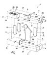
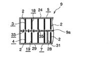
図1〜図4はこの発明のエバポレータの全体構成を示し、図5〜図8はその要部の構成を示す。なお、図2においては、熱交換チューブやフィンなどの具体的な図示は省略されている。 1 to 4 show the overall configuration of the evaporator of the present invention, and FIGS. 5 to 8 show the configuration of the main part thereof. Note that in FIG. 2, specific illustrations of heat exchange tubes, fins, and the like are omitted.
図1〜図4において、エバポレータ(1)は、幅方向を図1および図2に矢印Xで示す通風方向に向けるとともに長手方向を上下方向に向けた状態で左右方向(通風方向と直角をなす方向)に間隔をおいて配置された複数のアルミニウム製扁平状熱交換チューブ(2)からなる風下側チューブ列(3)および風上側チューブ列(4)と、風下側チューブ列(3)の熱交換チューブ(2)の上下両端側に長手方向を左右方向(熱交換チューブ(2)の並び方向)に向けて配置され、かつ風下側チューブ列(3)の全熱交換チューブ(2)が接続されたアルミニウム製風下側上ヘッダ部(5)およびアルミニウム製風下側下ヘッダ部(6)と、風上側チューブ列(4)の熱交換チューブ(2)の上下両端側に長手方向を左右方向に向けて配置され、かつ風上側チューブ列(4)の全熱交換チューブ(2)が接続されたアルミニウム製風上側上ヘッダ部(7)および風上側下ヘッダ部(8)とを備えている。 In FIGS. 1 to 4, the evaporator (1) is oriented in the left-right direction (perpendicular to the ventilation direction) with the width direction directed to the ventilation direction indicated by the arrow X in FIGS. 1 and 2 and the longitudinal direction directed to the vertical direction. The heat of the leeward tube row (3) and the leeward tube row (4) and the leeward tube row (3) consisting of a plurality of aluminum flat heat exchange tubes (2) arranged at intervals (direction). The exchange tube (2) is arranged on both the upper and lower ends with the longitudinal direction facing the left-right direction (the direction in which the heat exchange tubes (2) are arranged), and the total heat exchange tube (2) in the leeward tube row (3) is connected. The aluminum leeward upper header part (5) and the aluminum leeward lower header part (6), and the heat exchange tube (2) of the leeward tube row (4) on both the upper and lower ends in the longitudinal direction in the left-right direction. It is provided with an aluminum wind-up upper header portion (7) and an aluminum wind-up upper header portion (7) and an aluminum wind-up upper header portion (8) arranged so as to face and to which a total heat exchange tube (2) of the wind-up side tube row (4) is connected.
風下側上ヘッダ部(5)と風上側上ヘッダ部(7)、および風下側下ヘッダ部(6)と風上側下ヘッダ部(8)とは、たとえば1つのタンク(9)(11)内を左右方向にのびる板状の仕切部(9a)(11a)により通風方向に2つの空間に分割することにより設けられている。風下側上ヘッダ部(5)の右端部に冷媒入口(12)が設けられるとともに、風上側上ヘッダ部(7)の右端部に冷媒出口(13)が設けられている。風下側チューブ列(3)および風上側チューブ列(4)の全熱交換チューブ(2)は、上下両端寄りの一定長さ部分が、両上ヘッダ部(5)(7)および両下ヘッダ部(6)(8)内に挿入された状態で、両タンク(9)(11)にろう材によって接合されている(以下、ろう材による接合をろう付と称する)。全熱交換チューブ(2)の上端および下端は同一高さ位置にある。なお、全熱交換チューブ(2)の上端の高さ位置および下端の高さ位置は若干異なっている場合もある。また、風下側チューブ列(3)の熱交換チューブ(2)の数と風上側チューブ列(4)の熱交換チューブ(2)の数とは等しくなっている。 The leeward upper header portion (5) and the leeward upper header portion (7), and the leeward lower header portion (6) and the leeward lower header portion (8) are, for example, in one tank (9) (11). Is provided by dividing the space into two spaces in the ventilation direction by plate-shaped partition portions (9a) and (11a) extending in the left-right direction. A refrigerant inlet (12) is provided at the right end of the leeward upper header portion (5), and a refrigerant outlet (13) is provided at the right end of the leeward upper header portion (7). The total heat exchange tube (2) of the leeward side tube row (3) and the leeward side tube row (4) has a fixed length portion near both the upper and lower ends, which are both upper header portions (5) (7) and both lower header portions. (6) In the state of being inserted in (8), both tanks (9) and (11) are joined by brazing material (hereinafter, joining by brazing material is referred to as brazing). The upper and lower ends of the total heat exchange tube (2) are at the same height. The height position of the upper end and the height position of the lower end of the total heat exchange tube (2) may be slightly different. Further, the number of heat exchange tubes (2) in the leeward tube row (3) is equal to the number of heat exchange tubes (2) in the leeward tube row (4).
両チューブ列(3)(4)の隣接する熱交換チューブ(2)どうしの間の通風間隙および左右両端の熱交換チューブ(2)の外側に、それぞれ両チューブ列(3)(4)の熱交換チューブ(2)に跨って共有されるようにアルミニウム製コルゲートフィン(14)が配置されて両熱交換チューブ(2)にろう付され、左右両端のコルゲートフィン(14)の外側にそれぞれアルミニウム製サイドプレート(15)が配置されてコルゲートフィン(14)にろう付されている。左右両端の熱交換チューブ(2)とサイドプレート(15)との間も通風間隙となっている。両チューブ列(3)(4)の隣接する熱交換チューブ(2)どうしの間の通風間隙を通過した空気は、車両用空調装置が搭載されている車両の車室内に送り込まれる。 The heat of both tube rows (3) and (4) on the outside of the ventilation gap between the adjacent heat exchange tubes (2) of both tube rows (3) and (4) and the heat exchange tubes (2) on both the left and right ends, respectively. Aluminum corrugated fins (14) are arranged and brazed to both heat exchange tubes (2) so as to be shared across the exchange tubes (2), and are made of aluminum on the outside of the corrugated fins (14) on both the left and right ends. Side plates (15) are placed and brazed to corrugated fins (14). There is also a ventilation gap between the heat exchange tubes (2) on both the left and right ends and the side plates (15). The air that has passed through the ventilation gap between the adjacent heat exchange tubes (2) in both tube rows (3) and (4) is sent into the passenger compartment of the vehicle equipped with the vehicle air conditioner.
風下側チューブ列(3)に、連続して並んだ複数の熱交換チューブ(2)からなる3以上の奇数、ここでは3つチューブ群(16)(17)(18)が、冷媒入口(12)側端部(右端部)から他端部側(左端部)に向かって並んで設けられ、風上側チューブ列(4)に、連続して並んだ複数の熱交換チューブ(2)からなりかつ風下側チューブ列(3)のチューブ群(16)(17)(18)よりも1つ少ない数、ここでは2つのチューブ群(19)(21)が、冷媒出口(13)とは反対側の端部(左端部)から冷媒出口(13)側端部(右端部)に向かって並んで設けられている。以下、風下側チューブ列(3)の3つのチューブ群(16)(17)(18)を冷媒入口(12)側端部(右端部)から他端部(左端部)に向かって第1〜第3チューブ群といい、風上側チューブ列(4)の2つのチューブ群(19)(21)を冷媒出口(13)とは反対側端部から右端部に向かって第4および第5チューブ群というものとする。 In the leeward side tube row (3), three or more odd numbers consisting of a plurality of heat exchange tubes (2) arranged in succession, in which three tube groups (16) (17) (18), are the refrigerant inlets (12). ) It is provided side by side from the side end (right end) to the other end side (left end), and consists of a plurality of heat exchange tubes (2) continuously arranged in the windward tube row (4). One less than the tube group (16) (17) (18) in the leeward tube row (3), here the two tube groups (19) (21) are on the opposite side of the refrigerant outlet (13). It is provided side by side from the end (left end) toward the refrigerant outlet (13) side end (right end). Hereinafter, the three tube groups (16), (17), and (18) of the leeward side tube row (3) are moved from the refrigerant inlet (12) side end (right end) to the other end (left end). It is called the 3rd tube group, and the 2 tube groups (19) (21) of the windward tube row (4) are the 4th and 5th tube groups from the end opposite to the refrigerant outlet (13) toward the right end. Let's say.
第1チューブ群(16)が、風下側チューブ列(3)における冷媒入口(12)に最も近い位置にある最近チューブ群であり、第3チューブ群(18)が、風下側チューブ列(3)における冷媒入口(12)から最も遠い位置にある最遠チューブ群である。また、第4チューブ群(19)が、風上側チューブ列(4)における冷媒出口(13)から最も遠い位置にある最遠チューブ群であり、第5チューブ群(21)が、冷媒出口(13)に最も近い位置にある最近チューブ群である。風下側チューブ列(3)の第1および第2チューブ群(16)(17)を構成する熱交換チューブ(2)の合計数は、風上側チューブ列(4)の第5チューブ群(21)を構成する熱交換チューブ(2)の数と等しくなっており、第1および第2チューブ群(16)(17)の左右方向の合計幅は、第5チューブ群(21)の左右方向の幅と同一である。風下側チューブ列(3)の第3チューブ群(18)を構成する熱交換チューブ(2)の数は、風上側チューブ列(4)の第4チューブ群(19)を構成する熱交換チューブ(2)の数と等しくなっており、両チューブ群(18)(19)の左右方向の幅は同一である。 The first tube group (16) is the most recent tube group located closest to the refrigerant inlet (12) in the leeward tube row (3), and the third tube group (18) is the leeward tube row (3). It is the farthest tube group located at the position farthest from the refrigerant inlet (12) in. Further, the fourth tube group (19) is the farthest tube group located at the position farthest from the refrigerant outlet (13) in the windward tube row (4), and the fifth tube group (21) is the refrigerant outlet (13). ) Is the most recent tube group. The total number of heat exchange tubes (2) constituting the first and second tube groups (16) (17) of the leeward tube row (3) is the fifth tube group (21) of the leeward tube row (4). The total width of the first and second tube groups (16) (17) in the left-right direction is equal to the number of heat exchange tubes (2) constituting the fifth tube group (21) in the left-right direction. Is the same as. The number of heat exchange tubes (2) constituting the third tube group (18) of the leeward tube row (3) is the heat exchange tubes (19) constituting the fourth tube group (19) of the leeward tube row (4). It is equal to the number in 2), and the widths of both tube groups (18) and (19) in the left-right direction are the same.
風下側上ヘッダ部(5)内が板状の分割部(22)により左右方向に並んだ2つの区画(23)(24)に分割されることによって、風下側上ヘッダ部(5)に、冷媒入口(12)に通じるとともに、第1チューブ群(16)の熱交換チューブ(2)の上端部が通じる区画(23)と、第2および第3チューブ群(17)(18)の熱交換チューブ(2)の上端部が通じる区画(24)とが設けられ、風下側下ヘッダ部(6)内が分割部(25)により左右方向に並んだ2つの区画(26)(27)に分割されることによって、風下側下ヘッダ部(6)に、第1および第2チューブ群(16)(17)の熱交換チューブ(2)の下端部が通じる区画(26)と、第3チューブ群(18)の熱交換チューブ(2)の下端部が通じる区画(27)とが設けられている。また、風上側上ヘッダ部(7)内が分割部(28)により左右方向に並んだ2つの区画(29)(31)に分割されることによって、風上側上ヘッダ部(7)に、第4チューブ群(19)の熱交換チューブ(2)の上端部が通じる区画(29)と、冷媒出口(13)に通じるとともに、第5チューブ群(21)の熱交換チューブ(2)の上端部が通じる区画(31)とが設けられている。また、風上側下ヘッダ部(8)内の全体に、第4および第5チューブ群(19)(21)の熱交換チューブ(2)の下端部が通じる区画(32)が設けられている。 The inside of the leeward side upper header part (5) is divided into two sections (23) (24) arranged in the left-right direction by the plate-shaped dividing part (22), so that the leeward side upper header part (5) is divided into two sections (23) (24). Heat exchange between the compartment (23) leading to the refrigerant inlet (12) and the upper end of the heat exchange tube (2) of the first tube group (16) and the second and third tube groups (17) (18). A section (24) through which the upper end of the tube (2) communicates is provided, and the inside of the lower header part (6) on the leeward side is divided into two sections (26) (27) arranged in the left-right direction by the dividing part (25). By doing so, the lower header portion (6) on the leeward side communicates with the lower end portions of the heat exchange tubes (2) of the first and second tube groups (16) and (17), and the third tube group. There is a section (27) through which the lower end of the heat exchange tube (2) of (18) communicates. Further, the inside of the windward upper header portion (7) is divided into two compartments (29) and (31) arranged in the left-right direction by the dividing portion (28), so that the windward upper header portion (7) is divided into two sections (7). The upper end of the heat exchange tube (2) of the 5th tube group (21) as well as the compartment (29) through which the upper end of the heat exchange tube (2) of the 4 tube group (19) communicates with the refrigerant outlet (13). There is a section (31) that leads to. Further, a section (32) through which the lower end portions of the heat exchange tubes (2) of the fourth and fifth tube groups (19) and (21) are communicated is provided in the entire windward lower header portion (8).
以下、風下側上ヘッダ部(5)の冷媒入口(12)に通じるとともに第1チューブ群(16)の熱交換チューブ(2)の上端部が通じる区画(23)を第1区画、風下側下ヘッダ部(6)の第1および第2チューブ群(16)(17)の熱交換チューブ(2)の下端部が通じる区画(26)を第2区画、風下側上ヘッダ部(5)の第2および第3チューブ群(17)(18)の熱交換チューブ(2)の上端部が通じる区画(24)を第3区画、風下側下ヘッダ部(6)の第3チューブ群(18)の熱交換チューブ(2)の下端部が通じる区画(27)を第4区画、風上側上ヘッダ部(7)の第4チューブ群(19)の熱交換チューブ(2)の上端部が通じる区画(29)を第5区画、風上側下ヘッダ部(8)の第4および第5チューブ群(19)(21)の熱交換チューブ(2)の下端部が通じる区画(32)を第6区画、風上側上ヘッダ部(7)の冷媒出口(13)に通じるとともに、第5チューブ群(21)の上端部が通じる区画(31)を第7区画というものとする。 Hereinafter, the section (23) leading to the refrigerant inlet (12) of the leeward side upper header portion (5) and the upper end portion of the heat exchange tube (2) of the first tube group (16) is the first section, and the leeward side lower section. The second section is the section (26) through which the lower ends of the heat exchange tubes (2) of the first and second tube groups (16) and (17) of the header part (6) communicate, and the second section of the leeward upper header part (5). The section (24) through which the upper end of the heat exchange tube (2) of the second and third tube groups (17) (18) communicates is the third section, and the third tube group (18) of the leeward lower header portion (6) The section (27) through which the lower end of the heat exchange tube (2) communicates is the fourth section, and the section (2) through which the upper end of the heat exchange tube (2) of the fourth tube group (19) of the windward upper header portion (7) communicates ( 29) is the 5th compartment, and the compartment (32) through which the lower end of the heat exchange tubes (2) of the 4th and 5th tube groups (19) (21) of the windward lower header portion (8) is connected is the 6th compartment. The section (31) leading to the refrigerant outlet (13) of the windward upper header portion (7) and the upper end portion of the fifth tube group (21) is referred to as a seventh section.
第3区画(24)における第3チューブ群(18)の熱交換チューブ(2)の上端部が通じている部分と、第5区画(29)とは、上側タンク(9)内を風下側上ヘッダ部(5)と風上側上ヘッダ部(7)とに分割する仕切部(9a)に設けられた冷媒通過部(33)により通じさせられている。 The portion of the third compartment (24) through which the upper end of the heat exchange tube (2) of the third tube group (18) communicates with the fifth compartment (29) is leeward and upward in the upper tank (9). It is communicated by a refrigerant passage portion (33) provided in a partition portion (9a) that divides the header portion (5) and the windward upper header portion (7).
第4区画(27)と、第6区画(32)における第4チューブ群(19)の熱交換チューブ(2)の下端部が通じさせられている部分とは、下側タンク(11)内を風下側下ヘッダ部(6)と風上側下ヘッダ部(8)とに分割する仕切部(11a)に設けられた下部冷媒通過部(34)により通じさせられている。 The portion where the lower end of the heat exchange tube (2) of the fourth tube group (19) in the fourth compartment (27) and the sixth compartment (32) is communicated with each other is in the lower tank (11). It is communicated by a lower refrigerant passage portion (34) provided in a partition portion (11a) that divides the leeward side lower header portion (6) and the leeward upper lower header portion (8).
上述のようにして冷媒入口(12)、冷媒出口(13)、第1〜第5チューブ群(16)(17)(18)(19)(21)、第1〜第7区画(23)(26)(24)(27)(29)(32)(31)、および冷媒通過部(33)(34)が設けられることによって、冷媒は、風下側チューブ列(3)の最近チューブ群である第1チューブ群(16)、風下側チューブ列(3)の最遠チューブ群である第3チューブ群(18)および風上側チューブ列(4)の最遠チューブ群である第4チューブ群(19)の熱交換チューブ(2)内を上から下に流れることになり、これらのチューブ群(16)(18)(19)が下降流チューブ群となっている。また、冷媒は、風下側チューブ列(3)の第2チューブ群(17)、および風上側チューブ列(4)の第5チューブ群(21)の熱交換チューブ(2)内を下から上に流れることになり、これらのチューブ群(17)(21)が上昇流チューブ群となっている。したがって、両チューブ列(3)(4)に、複数の熱交換チューブ(2)からなり、かつ冷媒が上から下に流れる下降流チューブ群と冷媒が下から上に流れる上昇流チューブ群とが交互に並ぶように設けられている。 As described above, the refrigerant inlet (12), the refrigerant outlet (13), the first to fifth tube groups (16) (17) (18) (19) (21), the first to seventh compartments (23) ( With the provision of 26) (24) (27) (29) (32) (31) and refrigerant passages (33) (34), the refrigerant is a recent tube group of leeward tube rows (3). The first tube group (16), the third tube group (18) which is the farthest tube group of the leeward tube row (3), and the fourth tube group (19) which is the farthest tube group of the leeward tube row (4). ) Flows from top to bottom in the heat exchange tube (2), and these tube groups (16), (18), and (19) form a downward flow tube group. Further, the refrigerant flows from the bottom to the top in the heat exchange tube (2) of the second tube group (17) of the leeward side tube row (3) and the fifth tube group (21) of the leeward side tube row (4). It will flow, and these tube groups (17) and (21) are upflow tube groups. Therefore, in both tube rows (3) and (4), there are a group of downflow tubes in which the refrigerant flows from top to bottom and a group of upflow tubes in which the refrigerant flows from bottom to top, which are composed of a plurality of heat exchange tubes (2). They are provided so as to be arranged alternately.
すなわち、風下側チューブ列(3)の下降流チューブ群である第3チューブ群(18)の風上側に風上側チューブ列(4)の下降流チューブ群である第4チューブ群(19)が配置されるとともに、両チューブ群(18)(19)により1つのパスが構成され、第3チューブ群(18)および第3チューブ群(18)の冷媒流れ方向上流側に隣り合う上昇流チューブ群である第2チューブ群(17)の上端部が、風下側上ヘッダ部(5)に設けられかつ両端が閉鎖された1つの風下区画である第3区画(24)に通じさせられている。また、風上側チューブ列(4)における下降流チューブ群である第4チューブ群(19)の上端部が、風上側上ヘッダ部(7)に設けられ、かつ両端が閉鎖されるとともに第3区画(24)よりも左右方向の長さが短い1つの風上区画である第5区画(29)に通じさせられている。さらに、第3区画(24)および第5区画(29)はそれぞれ全体が1つとなった内部空間を有するとともに、第3区画(24)の第3チューブ群(18)が通じている部分と第5区画(29)とが冷媒通過部(33)によって通じさせられている。なお、第3および第4チューブ群(18)(19)を除いた残りのチューブ群(16)(17)(21)は、それぞれ単独で1つのパスを構成している。 That is, the fourth tube group (19), which is the downwind tube group of the leeward tube row (4), is arranged on the windward side of the third tube group (18), which is the downwind tube group of the leeward side tube row (3). At the same time, one path is formed by both tube groups (18) and (19), and the ascending flow tube groups adjacent to each other on the upstream side in the refrigerant flow direction of the third tube group (18) and the third tube group (18). The upper end of a second tube group (17) is communicated to a third compartment (24), which is one leeward compartment provided on the leeward upper header portion (5) and closed at both ends. Further, the upper end of the fourth tube group (19), which is the descending flow tube group in the windward tube row (4), is provided on the windward upper header portion (7), and both ends are closed and the third compartment is closed. It is connected to the fifth section (29), which is one upwind section having a shorter length in the left-right direction than (24). Further, the third compartment (24) and the fifth compartment (29) each have an internal space that is one as a whole, and the portion through which the third tube group (18) of the third compartment (24) communicates with the third compartment (24). The five compartments (29) are communicated with each other by the refrigerant passage portion (33). The remaining tube groups (16), (17), and (21) excluding the third and fourth tube groups (18) and (19) each independently constitute one path.
したがって、冷媒入口(12)から流入した冷媒は、次のように2つの経路を流れて冷媒出口(13)から流出するようになされている。第1の経路は、第1区画(23)、第1チューブ群(16)、第2区画(26)、第2チューブ群(17)、第3区画(24)、第3チューブ群(18)、第4区画(27)、第6区画(32)、第5チューブ群(21)および第7区画(31)であり、第2の経路は、第1区画(23)、第1チューブ群(16)、第2区画(26)、第2チューブ群(17)、第3区画(24)、第5区画(29)、第4チューブ群(19)、第6区画(32)、第5チューブ群(21)および第7区画(31)である。 Therefore, the refrigerant flowing in from the refrigerant inlet (12) flows through the two paths as follows and flows out from the refrigerant outlet (13). The first route is the first compartment (23), the first tube group (16), the second compartment (26), the second tube group (17), the third compartment (24), the third tube group (18). , 4th compartment (27), 6th compartment (32), 5th tube group (21) and 7th compartment (31), and the second route is the 1st compartment (23), 1st tube group ( 16), 2nd compartment (26), 2nd tube group (17), 3rd compartment (24), 5th compartment (29), 4th tube group (19), 6th compartment (32), 5th tube Group (21) and 7th compartment (31).
図5〜図7に示すように、上タンク(9)の仕切部(9a)における第3区画(24)の第3チューブ群(18)の熱交換チューブ(2)の上端部が通じさせられている部分と、第5区画(29)との間に位置する部分に、両区画(24)(29)を通じさせる複数の貫通穴(35)が左右方向に間隔をおいて設けられており、全貫通穴(35)により、第3区画(24)における第3チューブ群(18)の熱交換チューブ(2)の上端部が通じさせられている部分と、第5区画(29)とを通じさせる冷媒通過部(33)が構成されている。各貫通穴(35)の下端は第3区画(24)および第5区画(29)の内部空間の底面よりも上方に離隔しており、かつ全貫通穴(35)の下端が同一高さ位置にある。また、全貫通穴(35)の下端は、1つのパスを構成する下降流チューブ群である第3チューブ群(18)および第4チューブ群(19)の上端よりも下方の高さ位置にある。 As shown in FIGS. 5 to 7, the upper end of the heat exchange tube (2) of the third tube group (18) of the third section (24) in the partition portion (9a) of the upper tank (9) is communicated. A plurality of through holes (35) through which both compartments (24) and (29) are passed are provided at intervals in the left-right direction in the portion located between the portion and the fifth compartment (29). Through all through holes (35), the portion through which the upper end of the heat exchange tube (2) of the third tube group (18) in the third compartment (24) is communicated is passed through the fifth compartment (29). A refrigerant passage portion (33) is configured. The lower end of each through hole (35) is separated above the bottom surface of the internal space of the third compartment (24) and the fifth compartment (29), and the lower ends of all the through holes (35) are at the same height position. It is in. Further, the lower end of the total through hole (35) is located at a height lower than the upper ends of the third tube group (18) and the fourth tube group (19), which are the descending flow tube groups constituting one path. ..
ここで、冷媒通過部(33)を構成する全貫通穴(35)の総面積は、前記1つのパスを構成する風下側チューブ列(3)の下降流チューブ群である第3チューブ群(18)の全熱交換チューブ(2)の通路の総通路断面積よりも大きくなっている。すなわち、冷媒通過部(33)を構成する全貫通穴(35)の総面積をA、前記1つのパスを構成する風下側チューブ列(3)の下降流チューブ群である第3チューブ群(18)の全熱交換チューブ(2)の冷媒通路の総通路断面積をBとした場合、A>Bという関係を満たしている。さらに、冷媒通過部(33)を構成する全貫通穴(35)の総面積は、上タンク(9)の仕切部(9a)における第3区画(24)の第3チューブ群(18)の熱交換チューブ(2)の上端部が通じさせられている部分と、第5区画(29)との間に位置する部分の面積の40%以下であることが好ましい。 Here, the total area of all through holes (35) constituting the refrigerant passage portion (33) is the third tube group (18) which is the downflow tube group of the leeward tube row (3) constituting the one path. ) Is larger than the total passage cross-sectional area of the passage of the total heat exchange tube (2). That is, the total area of all through holes (35) constituting the refrigerant passage portion (33) is A, and the third tube group (18) which is a downward flow tube group of the leeward tube row (3) constituting the one path. ), When the total passage cross-sectional area of the refrigerant passage of the total heat exchange tube (2) is B, the relationship of A> B is satisfied. Further, the total area of all through holes (35) constituting the refrigerant passage portion (33) is the heat of the third tube group (18) of the third compartment (24) in the partition portion (9a) of the upper tank (9). It is preferably 40% or less of the area of the portion where the upper end portion of the exchange tube (2) is communicated and the portion located between the fifth compartment (29).
図8に示すように、風下側下ヘッダ部(6)の第4区画(27)と、風上側下ヘッダ部(8)の第6区画(32)における第4チューブ群(19)の熱交換チューブ(2)の下端部が通じている部分とを通じさせる下部冷媒通過部(34)は、下側タンク(11)内を風下側下ヘッダ部(6)と風下側下ヘッダ部(8)とに分割する仕切部(11a)を、第4区画(27)の全長にわたって除去することにより形成された1つの貫通穴(36)からなる。貫通穴(36)は、第4区画(27)の全高および全長にわたって形成されている。 As shown in FIG. 8, heat exchange between the fourth compartment (27) of the leeward lower header portion (6) and the fourth tube group (19) in the sixth compartment (32) of the leeward lower header portion (8). The lower refrigerant passage part (34) through which the lower end of the tube (2) communicates is the leeward side lower header part (6) and the leeward side lower header part (8) in the lower tank (11). It consists of one through hole (36) formed by removing the partition (11a) divided into the entire length of the fourth compartment (27). The through hole (36) is formed over the entire height and overall length of the fourth compartment (27).
上述したエバポレータ(1)は、圧縮機、冷媒冷却器としてのコンデンサおよび減圧器としての膨張弁とともに冷凍サイクルを構成し、カーエアコンとして車両、たとえば自動車に搭載される。カーエアコンの稼働時には、圧縮機、コンデンサおよび膨張弁を通過した冷媒が、上述した2つの経路を通って、冷媒入口(12)から流入するとともに冷媒出口(13)から流出し、冷媒が風下側チューブ列(3)の熱交換チューブ(2)内、および風上側チューブ列(4)の熱交換チューブ(2)内を流れる間に、隣り合う熱交換チューブ(2)どうしの間の通風間隙を通過する空気と熱交換をし、空気は冷却され、冷媒は気相となって流出する。 The above-mentioned evaporator (1) constitutes a refrigeration cycle together with a compressor, a condenser as a refrigerant cooler, and an expansion valve as a decompressor, and is mounted on a vehicle as a car air conditioner, for example, an automobile. When the car air conditioner is in operation, the refrigerant that has passed through the compressor, the condenser, and the expansion valve flows in from the refrigerant inlet (12) and outflows from the refrigerant outlet (13) through the above two paths, and the refrigerant flows downwind. While flowing through the heat exchange tube (2) of the tube row (3) and the heat exchange tube (2) of the wind-up side tube row (4), a ventilation gap between adjacent heat exchange tubes (2) is created. It exchanges heat with the passing air, the air is cooled, and the refrigerant flows out as a gas phase.
上述したエバポレータ(1)においては、冷媒通過部(33)を構成する全貫通穴(35)の下端が第3区画(24)および第5区画(29)の内部空間の底面よりも上方に離隔しているとともに全貫通穴(35)の下端が同一高さ位置にあり、かつ全貫通穴(35)の下端が、前記1つのパスを構成する2つの下降流チューブ群である第3チューブ群(18)および第4チューブ群(19)の上端よりも下方の高さ位置にあること、ならびに冷媒通過部(33)を構成する全貫通穴(35)の総面積が、第3チューブ群(18)の全熱交換チューブ(2)の冷媒通路の総通路断面積よりも大きくなっているので、第2チューブ群(17)から第3区画(24)内に流入した冷媒は、第3チューブ群(18)の熱交換チューブ(2)に流入するよりも冷媒通過部(33)を通って第5区画(29)に流入しやすくなり、しかも冷媒通過部(33)を通って第5区画(29)に流入する冷媒量が過剰になることが抑制される。したがって、風下側および風上側チューブ列(3)(4)における1つのパスを構成する第3チューブ群(18)および第4チューブ群(19)の全熱交換チューブ(2)を流れる冷媒量を均一化することが可能になって、エバポレータ(1)の冷却性能が優れたものになる。 In the above-mentioned evaporator (1), the lower ends of all the through holes (35) constituting the refrigerant passage portion (33) are separated above the bottom surfaces of the internal spaces of the third compartment (24) and the fifth compartment (29). A third tube group in which the lower ends of all through holes (35) are at the same height and the lower ends of all through holes (35) are two descending flow tube groups constituting the one path. The third tube group (18) and the fourth tube group (19) are located at a height below the upper end, and the total area of all the through holes (35) constituting the refrigerant passage portion (33) is the third tube group (18). Since it is larger than the total passage cross-sectional area of the refrigerant passage of the total heat exchange tube (2) of 18), the refrigerant flowing into the third section (24) from the second tube group (17) is the third tube. It is easier to flow into the fifth compartment (29) through the refrigerant passage (33) than into the heat exchange tube (2) of the group (18), and moreover, it is easier to flow into the fifth compartment (29) through the refrigerant passage (33). It is suppressed that the amount of the refrigerant flowing into (29) becomes excessive. Therefore, the amount of refrigerant flowing through the total heat exchange tubes (2) of the third tube group (18) and the fourth tube group (19) constituting one path in the leeward side and leeward side tube rows (3) (4). It becomes possible to make it uniform, and the cooling performance of the evaporator (1) becomes excellent.
この発明によるエバポレータは、カーエアコンを構成する冷凍サイクルに好適に用いられる。 The evaporator according to the present invention is suitably used for a refrigeration cycle constituting a car air conditioner.
(1):エバポレータ
(2):熱交換チューブ
(3):風下側チューブ列
(4):風上側チューブ列
(5):風下側上ヘッダ部
(6):風下側下ヘッダ部
(7):風上側上ヘッダ部
(8):風上側下ヘッダ部
(9a):仕切部
(16)(17)(18):第1〜第3チューブ群
(19)(21):第4および第5チューブ群
(24):第3区画(両端が閉鎖された風下区画)
(29):第5区画(両端が閉鎖された風上区画)
(33):冷媒通過部
(35):貫通穴
(1): Evaporator
(2): Heat exchange tube
(3): Downwind tube row
(4): Windward tube row
(5): Upwind header
(6): Downwind header
(7): Windward upper header
(8): Windward lower header
(9a): Partition
(16) (17) (18): 1st to 3rd tube groups
(19) (21): 4th and 5th tube groups
(24): Third section (leeward section with both ends closed)
(29): Fifth section (upwind section with both ends closed)
(33): Refrigerant passage
(35): Through hole
Claims (5)
風下区画の下降流チューブ群が通じさせられている部分と風上区画との間に、風上区画の全長にわたって仕切部が設けられ、冷媒通過部が、仕切部に左右方向に間隔をおいて形成された複数の貫通穴からなり、各貫通穴の下端が風下区画および風上区画の内部空間の底面よりも上方に離隔しており、冷媒通過部を構成する全貫通穴の下端が、前記1つのパスを構成する2つの下降流チューブ群の全熱交換チューブの上端よりも下方の高さ位置にあり、冷媒通過部を構成する全貫通穴の総面積をA、前記1つのパスを構成する風下側チューブ列の下降流チューブ群の全熱交換チューブの冷媒通路の総通路断面積をBとした場合、A>Bという関係を満たしているエバポレータ。 The leeward and leeward tube rows and the leeward and leeward tubes, which consist of a plurality of heat exchange tubes arranged in the longitudinal direction in the vertical direction and spaced in the horizontal direction and arranged side by side in the ventilation direction. It is equipped with both leeward and leeward upper and lower headers that are long in the leeward direction through which the upper and lower ends of the row of heat exchange tubes are communicated. The downwind tube group that flows downward from the bottom and the upwind tube group that the refrigerant flows from the bottom to the top are provided so as to be arranged alternately. There are three or more tube groups in the leeward tube row and the leeward side in the leeward tube row. There is one less tube group than the number of tube groups in the tube row, and one downwind tube group in the leeward tube row is placed on the windward side of one downwind tube group in the leeward tube row, and both One path is composed of the downwind tube group, and the upper end of the downwind tube group forming the one path in the leeward tube row and the upwind tube group adjacent to the upstream side in the refrigerant flow direction of the downwind tube group. However, the upper end of the downwind tube group, which is provided in the leeward upper header portion and is connected to one leeward compartment with both ends closed and constitutes the one path in the leeward tube row, is the leeward upper header. An internal space provided in a section, both ends of which are closed, and one upwind section that is shorter in the left-right direction than the leeward section, and one leeward section and one leeward section as a whole. And the upper end of the total heat exchange tube of the downwind tube group that is connected to the leeward section by the part where the downwind tube group of the leeward section is communicated and the upwind section are communicated by the refrigerant passing portion. together but is within downwind section, the upper end portion of the total heat exchange tubes downflow tube group that communicates with windward compartment is within windward compartment, the refrigerant that has flowed from the upflow tube group that communicates downwind section , Flowing to the downwind tube group side leading to the leeward section and flowing downward in the heat exchange tube of the downwind tube group, and at the same time, the refrigerant flowing in from the upwind tube group leading to the leeward section After flowing to the downwind tube group side leading to the leeward section and flowing into the upwind section through the refrigerant passage portion, flow downward in the heat exchange tube of the downwind tube group leading to the leeward section. It ’s an evaporator that is being done,
A partition is provided over the entire length of the leeward section between the portion through which the downward flow tube group of the leeward section is communicated and the leeward section, and the refrigerant passing portion is spaced from the partition in the left-right direction. It is composed of a plurality of formed through holes, the lower end of each through hole is separated above the bottom surface of the internal space of the leeward section and the upwind section, and the lower ends of all the through holes constituting the refrigerant passage portion are described above. It is located at a height below the upper end of the total heat exchange tube of the two descending flow tubes that make up one path, and the total area of all through holes that make up the refrigerant passage is A, and the one pass is made up. An evaporator that satisfies the relationship A> B, where B is the total passage cross-sectional area of the refrigerant passages of the total heat exchange tubes of the downwind tube group of the leeward side tube row.
Priority Applications (3)
| Application Number | Priority Date | Filing Date | Title |
|---|---|---|---|
| JP2016255489A JP6842915B6 (en) | 2016-12-28 | 2016-12-28 | Evaporator |
| US15/844,622 US10408510B2 (en) | 2016-12-28 | 2017-12-18 | Evaporator |
| CN201711444231.1A CN108253665B (en) | 2016-12-28 | 2017-12-27 | Evaporator with a heat exchanger |
Applications Claiming Priority (1)
| Application Number | Priority Date | Filing Date | Title |
|---|---|---|---|
| JP2016255489A JP6842915B6 (en) | 2016-12-28 | 2016-12-28 | Evaporator |
Publications (4)
| Publication Number | Publication Date |
|---|---|
| JP2018105593A JP2018105593A (en) | 2018-07-05 |
| JP2018105593A5 JP2018105593A5 (en) | 2019-09-12 |
| JP6842915B2 JP6842915B2 (en) | 2021-03-17 |
| JP6842915B6 true JP6842915B6 (en) | 2021-04-14 |
Family
ID=62629489
Family Applications (1)
| Application Number | Title | Priority Date | Filing Date |
|---|---|---|---|
| JP2016255489A Active JP6842915B6 (en) | 2016-12-28 | 2016-12-28 | Evaporator |
Country Status (3)
| Country | Link |
|---|---|
| US (1) | US10408510B2 (en) |
| JP (1) | JP6842915B6 (en) |
| CN (1) | CN108253665B (en) |
Families Citing this family (4)
| Publication number | Priority date | Publication date | Assignee | Title |
|---|---|---|---|---|
| AR107872A1 (en) | 2016-03-16 | 2018-06-13 | Godo Sushei Co Ltd | PROTEINASE B AND LACTASE SOLUTION USING ITS PROPERTIES AND METHOD TO PRODUCE IT |
| CN113330268B (en) * | 2019-02-04 | 2023-05-16 | 三菱电机株式会社 | Heat exchanger and air conditioner provided with same |
| CN112361663A (en) * | 2020-11-13 | 2021-02-12 | 珠海格力电器股份有限公司 | Heat exchanger and air conditioner with same |
| US11867438B2 (en) * | 2021-11-22 | 2024-01-09 | Air International (Us) Inc. | Multiple expansion device evaporators and HVAC systems |
Family Cites Families (14)
| Publication number | Priority date | Publication date | Assignee | Title |
|---|---|---|---|---|
| JPH11287587A (en) * | 1998-04-03 | 1999-10-19 | Denso Corp | Refrigerant evaporator |
| US6449979B1 (en) * | 1999-07-02 | 2002-09-17 | Denso Corporation | Refrigerant evaporator with refrigerant distribution |
| KR100590658B1 (en) * | 2004-04-28 | 2006-06-19 | 모딘코리아 유한회사 | Header Pipe of Evaporator for Automobile |
| JP5136050B2 (en) | 2007-12-27 | 2013-02-06 | 株式会社デンソー | Heat exchanger |
| JP5408951B2 (en) * | 2008-10-16 | 2014-02-05 | 三菱重工業株式会社 | Refrigerant evaporator and air conditioner using the same |
| US20100147501A1 (en) * | 2008-12-15 | 2010-06-17 | Delphi Technologies, Inc. | Curled manifold for evaporator |
| JP2010197008A (en) * | 2009-02-26 | 2010-09-09 | Mitsubishi Heavy Ind Ltd | Heat exchanger |
| US8485248B2 (en) * | 2009-12-15 | 2013-07-16 | Delphi Technologies, Inc. | Flow distributor for a heat exchanger assembly |
| US10047984B2 (en) * | 2010-06-11 | 2018-08-14 | Keihin Thermal Technology Corporation | Evaporator |
| JP5693346B2 (en) * | 2010-07-30 | 2015-04-01 | 株式会社ケーヒン・サーマル・テクノロジー | Evaporator |
| JP5740134B2 (en) * | 2010-10-25 | 2015-06-24 | 株式会社ケーヒン・サーマル・テクノロジー | Evaporator |
| JP5764345B2 (en) * | 2011-02-15 | 2015-08-19 | 株式会社ケーヒン・サーマル・テクノロジー | Evaporator |
| JP5759762B2 (en) * | 2011-03-22 | 2015-08-05 | 株式会社ケーヒン・サーマル・テクノロジー | Evaporator |
| JP2015157507A (en) | 2014-02-21 | 2015-09-03 | 株式会社ケーヒン・サーマル・テクノロジー | Air conditioner for vehicle |
-
2016
- 2016-12-28 JP JP2016255489A patent/JP6842915B6/en active Active
-
2017
- 2017-12-18 US US15/844,622 patent/US10408510B2/en active Active
- 2017-12-27 CN CN201711444231.1A patent/CN108253665B/en active Active
Also Published As
| Publication number | Publication date |
|---|---|
| CN108253665B (en) | 2020-08-11 |
| JP2018105593A (en) | 2018-07-05 |
| CN108253665A (en) | 2018-07-06 |
| US20180180335A1 (en) | 2018-06-28 |
| JP6842915B2 (en) | 2021-03-17 |
| US10408510B2 (en) | 2019-09-10 |
Similar Documents
| Publication | Publication Date | Title |
|---|---|---|
| JP5486782B2 (en) | Evaporator | |
| JP5740134B2 (en) | Evaporator | |
| JP5693346B2 (en) | Evaporator | |
| JP2006170598A (en) | Heat exchanger | |
| JP6842915B6 (en) | Evaporator | |
| JP5764345B2 (en) | Evaporator | |
| JP5759762B2 (en) | Evaporator | |
| JP2012197974A5 (en) | ||
| JP2013044504A5 (en) | ||
| JP2005195316A (en) | Heat exchanger | |
| JP2015034670A (en) | Evaporator | |
| JP5636215B2 (en) | Evaporator | |
| JP2013024517A (en) | Laminated heat exchanger | |
| JP2011257111A5 (en) | ||
| JP6785137B2 (en) | Evaporator | |
| JP2018087646A5 (en) | ||
| JP6617003B2 (en) | Heat exchanger | |
| JP2017015310A (en) | Evaporator | |
| JP5736164B2 (en) | Evaporator | |
| JP4617148B2 (en) | Heat exchanger | |
| JP5674376B2 (en) | Evaporator | |
| JP5238408B2 (en) | Heat exchanger | |
| JP5238421B2 (en) | Heat exchanger | |
| JP2018119747A (en) | Evaporator | |
| JP2018119736A (en) | Evaporator |
Legal Events
| Date | Code | Title | Description |
|---|---|---|---|
| A521 | Request for written amendment filed |
Free format text: JAPANESE INTERMEDIATE CODE: A523 Effective date: 20190805 |
|
| A621 | Written request for application examination |
Free format text: JAPANESE INTERMEDIATE CODE: A621 Effective date: 20190805 |
|
| A977 | Report on retrieval |
Free format text: JAPANESE INTERMEDIATE CODE: A971007 Effective date: 20200727 |
|
| A131 | Notification of reasons for refusal |
Free format text: JAPANESE INTERMEDIATE CODE: A131 Effective date: 20200804 |
|
| TRDD | Decision of grant or rejection written | ||
| A01 | Written decision to grant a patent or to grant a registration (utility model) |
Free format text: JAPANESE INTERMEDIATE CODE: A01 Effective date: 20210126 |
|
| A61 | First payment of annual fees (during grant procedure) |
Free format text: JAPANESE INTERMEDIATE CODE: A61 Effective date: 20210222 |
|
| R150 | Certificate of patent or registration of utility model |
Ref document number: 6842915 Country of ref document: JP Free format text: JAPANESE INTERMEDIATE CODE: R150 |
|
| S111 | Request for change of ownership or part of ownership |
Free format text: JAPANESE INTERMEDIATE CODE: R313113 |
|
| R360 | Written notification for declining of transfer of rights |
Free format text: JAPANESE INTERMEDIATE CODE: R360 |
|
| R360 | Written notification for declining of transfer of rights |
Free format text: JAPANESE INTERMEDIATE CODE: R360 |
|
| R371 | Transfer withdrawn |
Free format text: JAPANESE INTERMEDIATE CODE: R371 |
|
| S111 | Request for change of ownership or part of ownership |
Free format text: JAPANESE INTERMEDIATE CODE: R313113 |
|
| R350 | Written notification of registration of transfer |
Free format text: JAPANESE INTERMEDIATE CODE: R350 |
|
| R250 | Receipt of annual fees |
Free format text: JAPANESE INTERMEDIATE CODE: R250 |