JP2005238331A - Composite material and its manufacturing method - Google Patents
Composite material and its manufacturing method Download PDFInfo
- Publication number
- JP2005238331A JP2005238331A JP2005010020A JP2005010020A JP2005238331A JP 2005238331 A JP2005238331 A JP 2005238331A JP 2005010020 A JP2005010020 A JP 2005010020A JP 2005010020 A JP2005010020 A JP 2005010020A JP 2005238331 A JP2005238331 A JP 2005238331A
- Authority
- JP
- Japan
- Prior art keywords
- aluminum
- composite material
- main body
- mold
- ceramic particles
- Prior art date
- Legal status (The legal status is an assumption and is not a legal conclusion. Google has not performed a legal analysis and makes no representation as to the accuracy of the status listed.)
- Pending
Links
Images


Classifications
-
- H—ELECTRICITY
- H01—ELECTRIC ELEMENTS
- H01L—SEMICONDUCTOR DEVICES NOT COVERED BY CLASS H10
- H01L2224/00—Indexing scheme for arrangements for connecting or disconnecting semiconductor or solid-state bodies and methods related thereto as covered by H01L24/00
- H01L2224/01—Means for bonding being attached to, or being formed on, the surface to be connected, e.g. chip-to-package, die-attach, "first-level" interconnects; Manufacturing methods related thereto
- H01L2224/42—Wire connectors; Manufacturing methods related thereto
- H01L2224/47—Structure, shape, material or disposition of the wire connectors after the connecting process
- H01L2224/48—Structure, shape, material or disposition of the wire connectors after the connecting process of an individual wire connector
- H01L2224/4805—Shape
- H01L2224/4809—Loop shape
- H01L2224/48091—Arched
-
- H—ELECTRICITY
- H01—ELECTRIC ELEMENTS
- H01L—SEMICONDUCTOR DEVICES NOT COVERED BY CLASS H10
- H01L2924/00—Indexing scheme for arrangements or methods for connecting or disconnecting semiconductor or solid-state bodies as covered by H01L24/00
- H01L2924/0001—Technical content checked by a classifier
- H01L2924/00011—Not relevant to the scope of the group, the symbol of which is combined with the symbol of this group
-
- H—ELECTRICITY
- H01—ELECTRIC ELEMENTS
- H01L—SEMICONDUCTOR DEVICES NOT COVERED BY CLASS H10
- H01L2924/00—Indexing scheme for arrangements or methods for connecting or disconnecting semiconductor or solid-state bodies as covered by H01L24/00
- H01L2924/01—Chemical elements
- H01L2924/01015—Phosphorus [P]
-
- H—ELECTRICITY
- H01—ELECTRIC ELEMENTS
- H01L—SEMICONDUCTOR DEVICES NOT COVERED BY CLASS H10
- H01L2924/00—Indexing scheme for arrangements or methods for connecting or disconnecting semiconductor or solid-state bodies as covered by H01L24/00
- H01L2924/30—Technical effects
- H01L2924/301—Electrical effects
- H01L2924/3025—Electromagnetic shielding
Abstract
Description
本発明は、セラミック粒体とアルミニウムまたはアルミニウム合金からなる複合材およびその製造方法に関する。 The present invention relates to a composite material composed of ceramic particles and aluminum or an aluminum alloy, and a method for producing the same.
例えば、パワー半導体素子は大電流で駆動されるため発熱し、素子特性を維持するための放熱性に優れた放熱板が必要とされる。近年、特に高密度集積化や制御回路との混載による小型、軽量化が進められているため、高密度熱流の放散が重要な課題となっており、高熱伝導性の放熱基板が求められている。また、プラズマテレビ製造用の均熱板や、液晶パネル用ガラス基板に真空中でパターンを蒸着する際にも高熱が発生するため高熱伝導性の放熱基板が求められている。 For example, since a power semiconductor element is driven by a large current, it generates heat, and a heat dissipation plate with excellent heat dissipation is required to maintain element characteristics. In recent years, especially with the progress of miniaturization and weight reduction due to high density integration and mixed mounting with control circuit, dissipation of high density heat flow has become an important issue, and a highly heat conductive heat dissipation substrate is required. . Further, since a high heat is generated when a pattern is deposited on a soaking plate for manufacturing a plasma television or a glass substrate for a liquid crystal panel in a vacuum, a highly heat-conductive heat dissipation substrate is required.
さらに、小型パソコンや測定機器、プロジェクタ等の分野においては、半導体素子の高密度集積化が進むに従って、半導体素子の発熱量が増大する一方で、機器の小型化によって、放熱に困難な構造となる傾向にある。このように、筐体、ヒートシンク材に対しても高熱伝導性の放熱基板が求められている。
また、車両においては、例えば、制動の分野においてブレーキディスクには高い放熱性が要求されており、パワートランジスタ等を使うような部分では、高熱伝導性の放熱基板が求められている。
以上のように、様々な分野で熱伝導性の高い材料が求められており、この要望に対して、従来は、SiC(シリコンカーバイド)とA1(アルミニウム)との複合材であるSiC/A1系複合材が提案されている(例えば、特許文献1)。
Furthermore, in the fields of small personal computers, measuring instruments, projectors, etc., as the density of semiconductor elements increases, the amount of heat generated by the semiconductor elements increases. There is a tendency. Thus, a heat dissipation board with high thermal conductivity is also required for the housing and the heat sink material.
In a vehicle, for example, a brake disk is required to have high heat dissipation in the field of braking, and a heat dissipation board with high thermal conductivity is required in a portion where a power transistor or the like is used.
As described above, materials having high thermal conductivity are demanded in various fields, and in response to this demand, conventionally, a SiC / A1 system, which is a composite material of SiC (silicon carbide) and A1 (aluminum). A composite material has been proposed (for example, Patent Document 1).
しかし、金属板を使用する場合は熱膨張係数が大きい問題があり、一方、SiC/A1系複合材は熱伝導率が充分ではないという問題がある。
また、従来のSiC/A1系複合材では、アルミニウム溶湯の中にSiC粉末を分散させる方法、SiC粒体とアルミニウムまたはアルミニウム合金粒子をバインダーや焼結助剤を加えて成形し、次いで焼結する方法などがある。これらの方法において熱伝導率が充分でないのは、以下に示す理由によるものと考えられている。
・SiCの含有率が20%容積程度と低いため。
・SiCの粒度が10μ〜100μと非常に細かく、アルミニウムとの接触面積が非常に大きくなるため。
・SiCとアルミニウムとの界面にバインダーや焼結助剤の残留物が異物として残るため。
・SiCとアルミニウムとの界面に空気を含んだ空隙が存在するため、などである。
However, when a metal plate is used, there is a problem that the coefficient of thermal expansion is large. On the other hand, the SiC / A1 composite material has a problem that the thermal conductivity is not sufficient.
In addition, in the conventional SiC / A1-based composite material, a method in which SiC powder is dispersed in molten aluminum, SiC particles and aluminum or aluminum alloy particles are formed by adding a binder or a sintering aid, and then sintered. There are methods. The reason why the thermal conductivity is not sufficient in these methods is considered to be as follows.
-The content of SiC is as low as about 20% volume.
-SiC has a very fine particle size of 10-100 μm, and the contact area with aluminum becomes very large.
-Residues of binder and sintering aid remain as foreign matter at the interface between SiC and aluminum.
This is because there is a void containing air at the interface between SiC and aluminum.
さらに、以上のようなSiC/A1系複合材を、例えば放熱基板として、MPUやパワーモジュール等の半導体と接続して使用する場合、SiC/A1系複合材と半導体とを接着することが多い。場合によってはねじ止めすることもある。
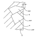
しかし、複合材を構成するSiCとA1との収縮率が違うため、複合材が収縮したとき、図16に示すように、SiC4の尖端部4Aが複合材100の表面から寸法Sだけ突出した状態となり、複合材100の表面に微妙な凹凸が生じている。凹凸は、例えば0.05mm程度であるが、凹凸にかわりはなく、複合材100の表面は平滑ではない。そのため、複合材100をそのままの状態で使用し、SiC/A1系複合材とパワーモジュール等の半導体とを接着、固定した場合、両者の対向する表面間に上記0.05mm程度の凹凸があることから、互いが充分に密着されない。その結果、半導体からの放熱がSiC/A1系複合材100に充分に伝達されなくなり、放熱基板としての充分な機能を果たせないという問題が生じている。
Furthermore, when the SiC / A1 composite material as described above is used as a heat dissipation substrate connected to a semiconductor such as an MPU or a power module, the SiC / A1 composite material and the semiconductor are often bonded. In some cases, it may be screwed.
However, since the shrinkage rates of SiC and A1 constituting the composite material are different, when the composite material is contracted, the
そこで、平滑性を得て密着性をよくするために、SiC/A1系複合材の表面を研削または研磨することが行われるが、SiCの尖端が多数突出しているうえ、そのSiCの硬度が大きいため、研削加工の場合、工具の損傷が早い。また、研磨加工の場合は、長時間にわたる作業となり効率が悪く、大量の需要がある場合に対応できない。
さらに、研削、研磨加工して平滑に仕上げられた取り付け面に、被取り付け部材を取り付けたとしても、SiC/A1系複合材と被取り付け部材との膨張率の違いから、繰り返し使用のうちに、互いが剥離してしまうという問題も生じている。
Therefore, in order to obtain smoothness and improve adhesion, the surface of the SiC / A1-based composite material is ground or polished. However, many SiC tips protrude and the hardness of the SiC is large. Therefore, in the case of grinding, the tool is damaged quickly. Also, in the case of polishing, the work takes a long time, the efficiency is poor, and it is not possible to cope with a large amount of demand.
Furthermore, even if the attached member is attached to the attachment surface that has been smoothed by grinding and polishing, due to the difference in expansion coefficient between the SiC / A1 composite and the attached member, There is also a problem that they are separated from each other.
本発明の目的は、高熱伝導性を得ることができるとともに、表面を容易に高精度の平滑面とできて被取り付け部材に密着して取り付けることができ、かつ、繰り返し使用しても被取り付け部材との間で剥離することがない複合材およびその製造方法を提供することにある。 It is an object of the present invention to obtain high thermal conductivity, to easily attach a surface to a member to be attached in a highly accurate and smooth surface, and to attach a member even when used repeatedly. It is to provide a composite material that does not peel between and a manufacturing method thereof.
本発明の複合材は、比較的大きな粒度のセラミック粒体が40〜85容積%、アルミニウムまたはアルミニウム合金が15〜60容積%からなるとともに、前記セラミック粒体間の間隙に前記アルミニウムまたはアルミニウム合金が連続相を形成し、かつ、前記セラミック粒体とアルミニウムまたはアルミニウム合金との界面に隙間がないようにした複合材において、前記セラミック粒体およびアルミニウムまたはアルミニウム合金で構成された板状の本体部と、この本体部の厚さ方向の少なくとも一方側表面を覆いかつ加工性に優れた被覆部とで形成されていることを特徴とする。 The composite material of the present invention comprises a ceramic particle having a relatively large particle size of 40 to 85% by volume, aluminum or an aluminum alloy of 15 to 60% by volume, and the aluminum or aluminum alloy is placed in a gap between the ceramic particles. In a composite material that forms a continuous phase and has no gap at the interface between the ceramic particles and aluminum or aluminum alloy, a plate-shaped main body portion made of the ceramic particles and aluminum or aluminum alloy; The body portion is formed of a covering portion that covers at least one surface in the thickness direction and is excellent in workability.
このような本発明によれば、複合材の本体部が、粒度が比較的大きなセラミック粒体をできるだけ多く含有させ、しかも、セラミック粒体とアルミニウムまたはアルミニウム合金とが連続相となっているので、互いの密着性が高まって形成される。セラミック粒体とアルミニウムとも、熱伝導性が鉄等他の金属と比べて優れており、その結果、高熱伝導性の複合材を得ることができる。 According to the present invention, since the main body portion of the composite material contains as many ceramic particles having a relatively large particle size as possible, and the ceramic particles and aluminum or aluminum alloy are in a continuous phase, It is formed with increased mutual adhesion. Both ceramic particles and aluminum are superior in thermal conductivity compared to other metals such as iron, and as a result, a composite material having high thermal conductivity can be obtained.
また、複合材を被取り付け部材に取付ける際には、加工性に優れた被覆部を加工すればよく、被覆部の表面を容易に高精度の平滑面とできる。その結果、被取り付け部材との間で充分に密着して取り付けることができ、被取り付け部材の熱が本体部に充分に伝達されて放熱されるので、放熱基板としての充分な機能を発揮することができる。 In addition, when the composite material is attached to the member to be attached, it is only necessary to process the covering portion with excellent workability, and the surface of the covering portion can be easily made a highly accurate smooth surface. As a result, it can be mounted in close contact with the mounted member, and the heat of the mounted member is sufficiently transmitted to the main body to be dissipated, so that it exhibits a sufficient function as a heat dissipation substrate. Can do.
さらに、本体部中に粒度が比較的大きなセラミック粒体が多く含有されているので、本体部の線膨張率を小さく抑えることができる。従って、寸法精度が極めて優れた本体部となり、このような本体部を被取り付け部材に取り付けたとき、被取り付け部材との膨張率の違いにより互いが剥離することを防止でき、その結果、繰り返し使用が可能となり、複合材の長寿命化を図ることができる。 Furthermore, since the main body contains a large number of ceramic particles having a relatively large particle size, the linear expansion coefficient of the main body can be kept small. Therefore, it becomes a main body part with extremely excellent dimensional accuracy, and when such a main body part is attached to a member to be attached, it can be prevented from being separated from each other due to a difference in expansion coefficient from the member to be attached. This makes it possible to extend the life of the composite material.
以上の複合材において、セラミック粒体の粒度とは、幅方向および厚さ方向の最大外接円の大きさをいい、比較的大きな粒度としては、0.15mm(100meshふるい上)以上あればよいが、0.3mm〜2.0mm(48〜49mesh)程度が好ましい。 In the above composite material, the particle size of the ceramic particles refers to the size of the maximum circumscribed circle in the width direction and the thickness direction, and the relatively large particle size may be 0.15 mm (above 100 mesh sieve) or more. And about 0.3 mm to 2.0 mm (48 to 49 mesh) is preferable.
本発明の複合材において、前記請求項1記載の被覆部が、前記本体部の表面に施された無電解ニッケルメッキからなる無電解ニッケルメッキ層で形成されていることが好ましい。
In the composite material of the present invention, it is preferable that the covering portion according to
このような本発明によれば、本体部の表面に、セラミックとアルミニウムとの収縮率の違いによる微妙な凹凸が形成されていても、外部電源を必要としない無電解ニッケルメッキ処理によれば、対象物がセラミックであっても施すことができるので、上記凹凸を解消することができる。
また、無電解ニッケルメッキ層を形成するには、例えば金型で製造した本体部を、前処理を施した後に、無電解ニッケルメッキ処理装置に収容してメッキ処理を行なえばよく、容易に被覆部を形成することができる。
さらに、無電解ニッケルメッキ層の表面は所定の平滑度を有する平滑面となる。そのため、被取り付け部材の種類によっては、新たに平面加工をしなくても、そのままの状態で用いることができ、その場合は加工の手間を省くこともできる。
According to the present invention, even if subtle irregularities due to the difference in shrinkage between ceramic and aluminum are formed on the surface of the main body, according to the electroless nickel plating process that does not require an external power supply, Since the object can be applied even if it is ceramic, the above unevenness can be eliminated.
In addition, in order to form an electroless nickel plating layer, for example, a main body manufactured with a mold may be pretreated and then accommodated in an electroless nickel plating apparatus to perform the plating process. The part can be formed.
Furthermore, the surface of the electroless nickel plating layer becomes a smooth surface having a predetermined smoothness. Therefore, depending on the type of the member to be attached, it can be used as it is without performing a new planar process, and in that case, the labor of the process can be saved.
以上の本発明において、無電解ニッケルメッキとしては、自己触媒型科学還元メッキ型を用いると好適である。
無電解ニッケルメッキは、外部電源を必要としないメッキ法であり、外部電源を必要とする電気メッキに対応するものである。外部電源を用いない金属析出法としては、金属の標準酸化還元電位(イオン化傾向)の差によって生じる置換(浸漬)メッキと、還元剤を用いる科学還元メッキとの2つがよく知られている。
In the present invention described above, it is preferable to use an autocatalytic chemical reduction plating type as the electroless nickel plating.
Electroless nickel plating is a plating method that does not require an external power source, and corresponds to electroplating that requires an external power source. Two well-known metal deposition methods that do not use an external power source are displacement (dipping) plating caused by a difference in standard oxidation-reduction potential (ionization tendency) of metal and scientific reduction plating using a reducing agent.
科学還元メッキは、金属イオンが還元剤によって還元析出するものであり、析出金属が還元剤の反応に対して触媒作用を有することに最大の特徴がある。つまり、この自己触媒作用により、金属析出反応は連続的に進行し、メッキ皮膜が成長する。
現在、広く工業的に利用されている無電解ニッケルメッキや、無電解銅メッキは、以上に述べた自己触媒型科学還元メッキである。
なお、置換(浸漬)メッキによって無電解ニッケルメッキ層を形成してもよい。また、無電解ニッケルメッキに替えて、本体部に無電解銅メッキ処理を施して被覆部を形成してもよい。
Scientific reduction plating is one in which metal ions are reduced and deposited by a reducing agent, and the greatest feature is that the deposited metal has a catalytic action on the reaction of the reducing agent. That is, by this autocatalytic action, the metal deposition reaction proceeds continuously, and the plating film grows.
Electroless nickel plating and electroless copper plating, which are currently widely used industrially, are the above-described self-catalytic scientific reduction plating.
An electroless nickel plating layer may be formed by displacement (immersion) plating. Moreover, it may replace with electroless nickel plating and may perform an electroless copper plating process to a main-body part, and may form a coating | coated part.
本発明の複合材において、請求項2に記載の複合材における前記無電解ニッケルメッキ層の表面には、電気メッキを施した電気メッキ層が形成されていることが好ましい。
In the composite material of the present invention, it is preferable that an electroplated layer subjected to electroplating is formed on the surface of the electroless nickel plated layer in the composite material according to
このような本発明によれば、本体部の表面に、セラミックとアルミニウムとの収縮率の違いによりセラミックが露出していても、まず、無電解ニッケルメッキを施すことで、セラミックとアルミニウムとの収縮率の違いによる凹凸を解消することができる。そして、無電解ニッケルメッキより経費が少なくてすむ電気メッキを無電解ニッケルメッキの表面に施すことで、全体の経費節減を図ることができる。
また、電気メッキ層の表面は所定の平滑度を有する平滑面となる。そのため、被取り付け部材の種類によっては、新たに平面加工をしなくても、そのままの状態で用いることができ、その場合は加工の手間を省くこともできる。
According to the present invention, even if the ceramic is exposed on the surface of the main body due to the difference in shrinkage between the ceramic and aluminum, first, the electroless nickel plating is applied to shrink the ceramic and aluminum. Unevenness due to the difference in rate can be eliminated. Then, by applying electroplating on the surface of the electroless nickel plating, which requires less cost than electroless nickel plating, the overall cost can be reduced.
Further, the surface of the electroplating layer is a smooth surface having a predetermined smoothness. Therefore, depending on the type of the member to be attached, it can be used as it is without performing a new planar process, and in that case, the labor of the process can be saved.
前記複合材を製造するため、本発明の製造方法は、請求項2に記載の複合材を製造する方法であって、金型を用いて前記セラミック粒体とアルミニウムまたはアルミニウム合金とを複合する際に、前記金型のキャビティ内に前記セラミック粒体を収容した後、前記金型のキャビティ内を真空で吸引しながら前記アルミニウムまたはアルミニウム合金の溶湯を前記セラミック粒体間の間隙に含浸させて前記本体部を形成し、この本体部が前記金型内で冷却された後、金型から取り出され、次いで、前記本体部の表裏面に無電解ニッケルメッキ処理を施して形成された無電解ニッケルメッキ層により被覆部を形成することを特徴とする。
In order to manufacture the composite material, the manufacturing method of the present invention is a method of manufacturing the composite material according to
通常の凝固を行い、セラミック粒体とアルミニウムとの界面、あるいはアルミニウムと遮蔽部材との界面に空隙ができたものについて、その空隙を除去する方法として以下の方法が有効である。
・複合材の本体部を、アルミニウムまたはアルミニウム合金が半溶融状態になる温度まで加熱し、圧力をかけて空隙を埋めてしまう方法。
・複合材の本体部を、アルミニウムまたはアルミニウム合金が軟化する温度で押出加工する方法。
・複合材の本体部を、アルミニウムまたはアルミニウム合金が軟化する温度で熱間圧延する方法。
・複合材の本体部を、アルミニウムまたはアルミニウム合金が軟化する温度で熱間鍛造する方法。
The following method is effective as a method for removing the voids in the solidified state where voids are formed at the interface between the ceramic particles and aluminum or between the aluminum and the shielding member.
A method in which the body of the composite material is heated to a temperature at which aluminum or an aluminum alloy is in a semi-molten state, and pressure is applied to fill the gap.
A method of extruding the main body of the composite material at a temperature at which aluminum or aluminum alloy softens.
A method of hot rolling the main body of the composite material at a temperature at which aluminum or aluminum alloy softens.
A method of hot forging the main body of the composite material at a temperature at which aluminum or aluminum alloy is softened.
前記記載のすべての方法において使用される溶湯について、セラミック微粉末をセラミック粒体に塗す他に、セラミック微粉末を、溶融したアルミニウムまたはアルミニウム合金の中に混入して攪拌した溶湯に使うことで、セラミック微粉末の含有量をさらに多くすることができる。
また、セラミック微粉末とアルミニウムまたはアルミニウム合金との濡れをよくするために、ニッケルのメッキをセラミック粒体に施してもよい。
Regarding the molten metal used in all the methods described above, in addition to coating the ceramic particles with the ceramic fine powder, the ceramic fine powder can be used for molten metal mixed in molten aluminum or aluminum alloy and stirred. Further, the content of the ceramic fine powder can be further increased.
Further, in order to improve the wettability between the ceramic fine powder and aluminum or aluminum alloy, nickel plating may be applied to the ceramic particles.
以下、本発明の実施形態を添付図面に基づいて説明する。
図1,2に示すように、第1実施形態の複合材1は本体部2と、この本体部2の表裏面を覆い、かつ本体部2と一体化された被覆部2Aとで構成されている。
Hereinafter, embodiments of the present invention will be described with reference to the accompanying drawings.
As shown in FIGS. 1 and 2, the
本体部2は、分散したセラミック粒体4の間に、アルミニウムまたはアルミニウム合金(以下、単にアルミニウムという)5を隙間なく混入して形成された連続相を有している。複合材1の厚さTは、例えば、3mmとなっているが、この厚さTは、3mmに限定されず、3mm以上でもよく、あるいは3mm以下でもよい。
The
セラミック粒体4としては、SiCの他、A1N、BN、カーボン等の粒体が用いられ、その粒度は比較的大きなものが用いられている。比較的大きな粒度としては、例えば、0.15mm(100meshふるい上)以上あればよいが、製品の厚さなどを考慮に入れると、0.3mm〜2.0mm(48〜9mesh)程度の粒度範囲が好ましい。
As the
ここで、セラミック粒体4の粒度が0.15mm未満であると、セラミック粒体4間の間隙が小さくなりすぎて、アルミニウムの溶湯が入り込まなくなり、含浸不良を起こす。また、セラミック粒体4の使用に際しては、全体をほぼ同じ粒度のものとしてもよいが、異なる粒度のセラミック粒体4を組み合わせて使用してもよい。
なお、セラミック粒体4の粒度とは、幅方向および厚さ方向の最大外接円の大きさをいう。また、セラミック粒体4は粒体ばかりでなく、繊維状のものを併用してもよい。さらに、カーボンとしては、カーボンブラック、カーボンバルーン等を用いることができる。
そして、本実施形態ではセラミック粒体4として、例えば、粒度0.7mmのSiC4が使用されている。
Here, when the particle size of the
The particle size of the
In this embodiment, for example,
SiC4の量は、40〜85容積%が適当である。40容積%未満であれば、複合材1における本体部2の熱伝導率が高くならず、85容積%を越えると本体部2の強度が不十分となる。一方、アルミニウムの量は、SiC4の量に対応して15〜60容積%とされている。
このように、本体部2の中に、比較的粒度が大きいSiC4を比較的多量に含有させたので、熱伝導率を200W/mK以上、線膨張係数を9〜12×10−6程度にすることができる。
また、SiC4には、予めセラミック微粉末が塗されている。このセラミック微粉末の量はSiC4に対して、例えば、1:0.2〜0.4の割合とすることが好ましい。
A suitable amount of SiC4 is 40 to 85% by volume. If it is less than 40% by volume, the thermal conductivity of the
As described above, since a relatively large amount of SiC4 having a relatively large particle size is contained in the
Moreover, SiC4 is coated with ceramic fine powder in advance. The amount of the ceramic fine powder is preferably set to a ratio of, for example, 1: 0.2 to 0.4 with respect to SiC4.
以上の本体部2は、図3に示すような製造装置10で製造することができる。
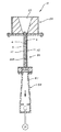
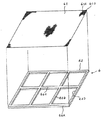
製造装置10は、金型20と、注湯部30と、吸引部40とを含み構成されている。金型20は、一対の板状体21,22、および板状体21,22と直交しかつ結合される一対の側板(図示しない)を含み構成され、これらの板状体21,22および側板によりキャビティ20Aが形成されている。
注湯部30には、キャビティ20Aの上端に連通する湯道31が形成されている。また、キャビティ20Aの下端は、真空ポンプPによって吸引される真空ボックス41に連通している。
The
The
The pouring part 30 is formed with a
本体部2の製造に際しては、まず、金型20のキャビティ20Aの内部に、セラミックの微粉末を塗したSiC4を充填する。
次いで、キャビティ20A内を真空ポンプPによって吸引しながら、アルミニウム5の溶湯を注湯部30の湯道31から流入、充填する。このアルミニウム5の溶湯は、キャビティ20A内のSiC4同士の間隙に含浸して本体部2を形成する。
なお、金型20の下部と吸引部40との間には、例えばシート状の受け部材(図示しない)が設けられている。この受け部材には、アルミニウム5の溶湯は通さないが、エアを吸引できる極細の孔が多数あけられている。
In manufacturing the
Next, while the inside of the
A sheet-like receiving member (not shown) is provided between the lower part of the
以上のように金型20で形成された本体部2を冷却後に取出したとき、その表裏面には、前述のようにアルミニウム5とSiC4とが現われ、かつ両者5,4の収縮率の違いにより、本体部2の表裏面は、前述のように微妙な凹凸となっている。
As described above, when the
アルミニウム溶湯の凝固の時に、普通に凝固させると、アルミニウム溶湯の凝固収縮が大きいために、SiC4とアルミニウム5との界面に真空の空隙ができてしまう。この真空の空隙は熱伝導率を著しく低下させる。従って、この真空の空隙は除去しなければならない。真空の空隙を除去する方法として以下の各方法が有効である。
・本体部2を、その構成要素のアルミニウム5が半溶融状態になる温度まで加熱し、圧力をかけて、アルミニウム5で真空の空隙を埋めてしまう方法。
・本体部2を、その構成要素のアルミニウム5が軟化する温度で押し出す方法。この方法では、押し出し加工時に、軟化状態のアルミニウム5が真空の空隙を埋めてしまう。
・本体部2を、その構成要素のアルミニウム5が軟化する温度で熱間圧延する方法。
・本体部2を、その構成要素のアルミニウム5が軟化する温度で熱間鍛造する方法。
・キャビティ20A内を真空で吸引しながら、アルミニウム5の溶湯を注入している間に、同時にアルミニウム溶湯を加圧する。
If the molten aluminum is solidified normally when the molten aluminum is solidified, the solidified shrinkage of the molten aluminum is large, so that a vacuum gap is formed at the interface between the
A method in which the
A method of extruding the
A method of hot rolling the
A method of hot forging the
-While the
前記いずれの方法においても、SiC4の粒度を0.15mm以上と大きくすることができる。また、その含有量も40容積%以上とすることができる。さらに、SiC4とアルミニウム5以外は特に何も使わないでよい。そして、最後にSiC4とアルミニウム5との界面にできる空隙を除去することが可能となる。その結果、より熱伝導性に優れた複合材1の製造が可能となる。
In any of the above methods, the particle size of SiC4 can be increased to 0.15 mm or more. Moreover, the content can also be 40 volume% or more. Further, nothing other than SiC4 and
図4に示すように、被覆部2Aは、本体部2の表裏面に施工された厚さ寸法がDの無電解ニッケルメッキ層で構成されている。この無電解ニッケルメッキ層の厚さDは、例えば10μ〜50μに形成されており、製造された本体部2の前記微妙な凹凸を埋めることができる厚さになっている。
無電解ニッケルメッキ層は、金型20から取り出した本体部2の表裏面に所定の前処理を施した後、その本体部2を、図示しない無電解ニッケルメッキ用装置に収容し、無電解ニッケルメッキ処理を施して形成される。そして、この無電解ニッケルメッキ層により本体部2の表裏面の微妙な凹凸が埋められ、高精度の平滑面となっている。そのため、被取付け部材の種類によっては、表面の二次加工をしなくても、そのままの状態で使用することができる。
As shown in FIG. 4, the covering
The electroless nickel plating layer is subjected to a predetermined pretreatment on the front and back surfaces of the
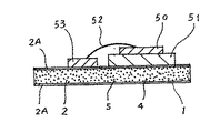
以上のような複合材1の使用状態の一例が模式図として、図5に示されている。
この使用例では、被覆部2Aの表面が、無電解ニッケルメッキ処理された状態のままのものが使用され、研磨加工等の二次加工は行なわれていない。なお、被覆部2Aの表面は、被取付け部材との間で要求される密着度を満たす程度に平滑面となっている
An example of the usage state of the
In this use example, the surface of the covering
図5に示すように、例えばMPU用のパワー半導体素子50は、A1Nチップ51に固着されており、このA1Nチップ51は、複合材1の被覆部2Aに固着されている。従って、複合材1と、A1Nチップ51および導体回路配線53とが、高精度の密着度で相互に取り付けられている。また、パワー半導体素子50には、ワイヤ52により導体回路配線53が接続されている。
As shown in FIG. 5, for example, a
以上のような本実施形態によれば、次の効果がある。
(1)複合材1の本体部2が、粒度が比較的大きなSiC4が40〜85容積%、アルミニウム5が15〜60容積%からなり、SiC4間の間隙にアルミニウム5が連続相を形成し、かつ、SiC4とアルミニウム5との界面に隙間がないように形成されているので、熱伝導率を200W/mK以上にすることができる。その結果、高熱伝導性の複合材1を得ることができ、優れた放熱基板として利用することができる。
According to the present embodiment as described above, the following effects are obtained.
(1) The
(2)複合材1の線膨張係数を9〜12×10−6程度に抑えることができるので、複合材1が膨張しにくい。従って、パワートランジスタ等の被取付け部材に取付けたとき、互いの膨張率の違いから生じる、繰り返し使用による剥がれ等を防止することができ、複合材1の長寿命化を図ることができる。
(2) Since the linear expansion coefficient of the
(3)本体部2の表面に、SiC4とアルミニウム5との収縮率の違いによる微妙な凹凸が形成されていても、対象物がSiC4であっても無電解ニッケルメッキ処理を施すことができるので、上記凹凸を解消することができる。無電解ニッケルメッキ層の表面は高精度の平滑面となっているので、複合材1を、パワートランジスタ等の被取付け部材に取付けるために、研削加工、あるいは研磨加工を省略することも可能となり、その分の手間を省くことができる。
(3) Since the surface of the
(4)本体部2の被覆部2Aが無電解ニッケルメッキ層により形成され、その表面は、例えば10〜20μ程度の凹凸となった高精度の平滑面となっているので、熱伝導率が200W/mK以上ある複合材1を、パワートランジスタ、各種半導体デバイス部品、液晶パネル用のガラス基板、プラズマテレビ製造用の均熱板等の被取付け部材に対して高精度の密着性を維持して接続させることができる。従って、急速な放熱が可能となるので、放熱基板としての機能を充分に果たすことができる。
(4) Since the covering
(5)SiC4には予めセラミック微粉末が塗されているので、SiC4の粒体間の隙間にアルミニウム5が充填され、収縮する際、SiC4にまとわりついたセラミックの微粉末に、アルミニウム5の収縮時にアルミニウム5を引っ張る作用が生じるため、アルミニウム5の収縮をわずかでも抑えることができる。その結果、SiC4の粒体とアルミニウム5との界面に生じる空隙を少なくでき、より高性能の熱伝導性を有する複合材1とできる。
(5) Since
(6)複合材1の熱伝導率が200W/mK以上となっており、高熱伝導性のものとなっているので、複合材1を、高熱伝導性が必要な製品、例えば、プロジェクタの熱源である電灯の放熱対策に利用したり、パネルヒータのパネル本体、遠赤外線ヒータの発熱面、アイロンの掛け面用、例えばフライパンや、炊飯器の釜や、調理用の鍋等、料理用の器具に用いることもでき、多方面での利用が可能となる。
(6) Since the thermal conductivity of the
次に、図6に基づいて本発明の第2実施形態を説明する。
この実施形態および以下の各実施形態において、前記第1実施形態の各部材と同一構成部材には、同一符号を付すとともに、その詳細な説明は省略または簡略化する。
Next, a second embodiment of the present invention will be described based on FIG.
In this embodiment and the following embodiments, the same components as those of the first embodiment are denoted by the same reference numerals, and detailed description thereof is omitted or simplified.
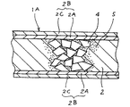
本第2実施形態の複合材1Aは、前記本体部2と、この本体部2の表裏面を覆い、かつ当該本体部2と一体となった被覆部2Bとで構成されている。
被覆部2Bは2層構造とされ、本体部2側の第1層が前記被覆部2Aで形成され、この被覆部2Aの表面に電気メッキを施して形成された電気メッキ層2Cが第2層となっている。電気メッキ層2Cは、本体部2に無電解ニッケルメッキ処理を施した後、図示しない電気メッキ用のメッキ槽に収容して形成される。
The
The covering portion 2B has a two-layer structure, the first layer on the
以上のような第2実施形態によれば、前記(1)〜(6)とほぼ同様の効果の他、次のような効果が得られる。
(7)本体部2の表面に、セラミック4とアルミニウム5との収縮率の違いによりセラミック4が露出していても、無電解ニッケルメッキ処理により、本体部表面の凹凸を解消することができるうえに、無電解ニッケルメッキより経費が少なくてすむ電気メッキが無電解ニッケルメッキの表面に施されているので、全体の経費節減を図ることができる。
According to the second embodiment as described above, the following effects can be obtained in addition to substantially the same effects as the above (1) to (6).
(7) Even if the ceramic 4 is exposed on the surface of the
次に、図7〜図9に基づいて本発明の第3実施形態を説明する。
第3実施形態の複合材1Bは、本体部3と、この本体部3の一表面を覆うとともに当該本体部3と一体となった被覆部3Aとで構成されている。
Next, a third embodiment of the present invention will be described with reference to FIGS.
The
本体部3は、前記本体部2とほぼ同様の構成となっているが、被覆部3Aが本体部3と同時に製造される点が、前記第1、第2実施形態と異なっている。
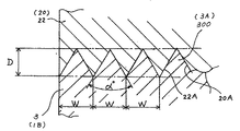
被覆部3Aは、図8に示すように、本体部3の一方側表面から外側に突出し、かつ、図8の紙面直交方向である縦方向(次に述べる金型20においてアルミニウム溶湯の流れ方向)に連続した多数条の突出部300により形成されている。
この突出部300は、金型20のキャビティ20Aを構成する一対の板状体21,22、および図示しない一対の側板のうち、一方の板状体22に形成された縦溝22Aにアルミニウムの溶湯を流入、充填することにより形成される。
The
As shown in FIG. 8, the covering
The
縦溝22Aは、図9に示すように、前記一方の板状体22の一方側表面全面に、アルミニウムの溶湯が流れる縦方向(実施形態では垂直方向)に連続して形成されている。この縦溝22Aは、図8に示すように、根元の幅寸法Wが例えば0.5mmで、抜け勾配としての角度αが例えば約60°で、深さDが例えば0.5mmの断面三角形状の空間に形成されている。そのため、縦溝22Aには、粒度が0.7mmのSiC4がほとんど侵入できない構成となっている。
As shown in FIG. 9, the
そして、隣り合う縦溝22A同士は幅方向に隙間なく連続しており、それらの縦溝22Aを、当該縦溝22Aと直行する方向から見たとき鋸歯状になっている。
なお、縦溝22Aは、垂直に形成されているだけでなく、例えば傾斜角5度程度のわずかな傾斜に沿って形成されていてもよい。あるいは、例えばS字状に蛇行した溝でもよい。要は、アルミニウム5の溶湯がスムーズに流入できる溝であればよい。
Adjacent
Note that the
縦溝22Aの幅W、角度αおよび深さDの寸法は、上記寸法0.5mmに限定されない。例えば、幅Wを0.5mm以下としてもよく、あるいは0.5mm以上に形成してもよい。ただし、幅Wをあまり小さくすると、アルミニウム5の溶湯が流れにくくなるので、例えば0.3mm程度までに抑えた方が好ましい。また、あまり大きくすると、SiC4が侵入しやすくなるので、例えば0.6mm程度までに抑えた方が好ましい。
The dimensions of the width W, the angle α, and the depth D of the
以上の複合材1Bは、前述した図3に示す製造装置10で製造することができる。
すなわち、製造装置10の金型20を構成する一方の板状体22を、前記縦溝22Aが形成されたものとすることで、前述と同じ手順により製造することができる。なお、縦溝22Aが前記キャビティ20Aに臨むように金型20の板状体22が配置される。
The above composite material 1B can be manufactured with the
That is, one plate-
複合材1Bを製造した後、突出部300からなる被覆部3Aの平滑面を得るために平面加工をする必要が生じる。この場合、例えばホットプレスを使用することができる。その手順としては、まず、本体部3を所定の載置台(図略)の上に載せ、突出部300の上端にホットプレスを当接させた後、ホットプレスにより徐々に熱を加えながら、多数状の突出部300の先端を押圧する。これにより、突出部300が潰され、平滑面が形成される。
After the composite material 1B is manufactured, it is necessary to perform planar processing in order to obtain a smooth surface of the covering
あるいは、多数状の突出部300からなる被覆部3Aを、工具により研削あるいは研磨して平面加工し、高精度な平滑面としてもよい。
また、被覆部3Aの表面加工は、前述のホットプレス、研削、研磨加工に限らず、例えば、圧延加工で行ってもよい。すなわち、複合材1Bを金型20から取り出した後、その複合材1Bを、所定温度、例えば200℃〜300℃で焼きなまし処理して圧延加工しやすいようにし、圧延ロール間を通すことにより突出部300、つまり被覆部3Aを圧延し、これにより、高精度な平滑面としてもよい。この場合、断面三角形状の突出部300の頂点と谷との間の寸法、例えば前記0.5mmの寸法の半分、つまり、0.25mmだけ圧延するようにすれば、頂点と谷とが互いに埋まり合って、容易に平滑な仕上げ面とすることができる。従って、複合材1Bの表面には圧延加工された0.25mmの被覆部3Aが形成されていることになる。
Alternatively, the covering
Further, the surface processing of the covering
以上のような第3実施形態によれば、前記(1)、(2)、(5)、(6)とほぼ同様の効果の他、次のような効果が得られる。
(8)一方の板状体22に形成された多数条の縦溝22Aは、根元の幅寸法Wが0.5mmとなっているので、粒度が0.7mmのSiC4が、キャビティ20A内を勢いよく連続して落下するときそれらの縦溝22Aに侵入することはほとんどない。その結果、複合材1の表面を平面加工する際、縦溝22A内に充填されて形成されたアルミニウムからなる突出部300を加工すればよいので、容易に高精度の平滑面ととすることができる。
According to the third embodiment as described above, the following effects can be obtained in addition to substantially the same effects as the above (1), (2), (5), and (6).
(8) Since the root width dimension W of the multiple
(9)被覆部3Aを構成する多数条の突出部300は、金型20のキャビティ20Aに形成された多数状の縦溝22Aにアルミニウム5の溶湯を流入させることで形成でき、縦溝22Aはアルミニウム5の溶湯の流入方向と同じ方向の縦方向に形成されているので、アルミニウム5の溶湯がスムーズに流れる。従って、突出部300の幅寸法Wが小さくても突出部300を容易に形成できる。
(9) The
(10)被覆部3Aを構成する多数条の突出部300の平面加工は、ホットプレスを利用したり、工具による研削加工、研磨加工、あるいは、所定温度で突出部300のアルミニウムを加熱して焼きなまし処理を行い、突出部300を圧延加工して高精度な仕上げ面を得ることもできる。その結果、表面加工の選択が拡がるので、設備に応じた表面加工を行うことができる。
(10) Planar processing of the
次に、図10〜図12に基づいて本発明の第4実施形態を説明する。
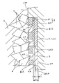
図10に示すように、本第4実施形態の複合材1Cは、本体部7と、この本体部7における厚さ方向の一方側表面から寸法Lだけ内側に入った位置に埋設された遮蔽部材6とを含み構成され、この遮蔽部材6と一方側表面との間に被覆部7Aが形成されている。
Next, a fourth embodiment of the present invention will be described based on FIGS.
As shown in FIG. 10, the
前記遮蔽部材6は、図11、図12に示すように、金網61とこの金網61を支持する支持部材62とで構成されている。
金網61は、針金部材61Aを編み込んで形成されている。針金部材61Aの銅線の太さは、線径が例えば0.5mmのものが用いられ、その網目は、例えば0.4mmとなっている。そして、この0.4mmの網目により連通孔61Dが構成されている。
また、連通孔61Dが0.4mmとなっているので、図12に示すように、粒度が例えば0.7mmのSiC4は、連通孔61Dを通り抜けることができず、SiC4の尖端4Aの一部が引っかかった状態となっている。
As shown in FIGS. 11 and 12, the shielding member 6 includes a
The
Further, since the communication hole 61D is 0.4 mm, as shown in FIG. 12,
支持部材62は、例えば0.5mmの厚さの銅板で形成されており、枠体62A、縦桟62B、および横桟62Cを含み構成され、例えば6つの大きな開口部62Dが形成されている。枠体62A、縦桟62B、および横桟62Cの幅寸法は、例えば0.5mmに形成されている。
The
そして、遮蔽部材6を金型200のキャビティ200Aに装着したとき、キャビティ200Aの一方側表面と金網61との間隔は寸法Lとなっている。また、キャビティ200Aの一方側表面から寸法L1だけ内側に入った位置で平面加工すれば、SiC4に触れずに加工することができ、かつ仕上げ記号で示したように、高精度の平滑面7Bを得ることができる。
When the shielding member 6 is attached to the
金網61が被覆部7A内に埋設されていても、金網61および支持部材62は銅で形成されており、銅の熱伝導率は、0.938cal/cm・/sec/°Cであるのに対して、アルミニウム5の熱伝導率0.534cal/cm・/sec/°Cであり、銅の方がアルミニウム5よりもはるかに熱伝導率が大きい。従って、被覆部4Aに金網61、支持部材62が埋設されていても、複合材1Cの高熱伝導性を何ら阻害するものではない。
また、銅の融点が1083度であるのに対して、アルミニウム5の融点が660度であり、銅の方がアルミニウム5よりはるかに高いので、予熱されている金型のキャビティ200Aにアルミニウム5の溶湯を注入しても、金網61および支持部材62がへたることはない。
Even though the
In addition, the melting point of copper is 1083 degrees, whereas the melting point of
以上のような第4実施形態によれば、前記(1)、(2)、(5)、(6)とほぼ同様の効果の他、次のような効果が得られる。
(11)キャビティ20Aの一方側表面から所定寸法Lだけ入り込んだ内部に埋設された金網61が連通孔61Dを有し、この連通孔61Dの孔径は使用されるSiC4の粒度より小さく形成されているので、金網61と本体部7の一方側表面との間の被覆部7Aにアルミニウム5は充填されるが、SiC4は入り込まない。従って、複合材1Cの使用に際しては、被覆部7Aを構成するアルミニウム5と支持部材62の一部とを平面加工すればよいので、加工が容易となり、かつ短時間で高精度の平滑面7Bを得ることができる。
According to the fourth embodiment as described above, the following effects can be obtained in addition to substantially the same effects as the above (1), (2), (5), and (6).
(11) A
(12)金網61は銅製の針金部材61を編み込んで形成されるので、容易に製作することができるとともに、針金部材61を編みこむ際に、網目の大きさ、つまり連通孔61Dを任意に変えることができるので、粒度の異なるSiC4に柔軟に対応することができる。
(12) Since the
(13)遮蔽部材6が、金網61を支持部材62に取り付けて構成されているので、金網61が波打ったり、一部が凹んだりすることがない。そのうえ、銅の融点がアルミニウム5の融点よりはるかに高いので、予熱されている金型のキャビティ200Aにアルミニウム5の溶湯を注入しても、金網61および支持部材62がへたることはない。従って、遮蔽部材6を安定して装着することができる。
(13) Since the shielding member 6 is configured by attaching the
次に、図13に基づいて本発明の第5実施形態を説明する。
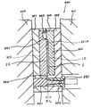
前記各実施形態では、本体部2、本体部3、本体部7を製造するのに製造装置10を用いていたが、本第5実施形態は、ダイカスト機300により複合材1Dを製造するものである。
Next, a fifth embodiment of the present invention will be described based on FIG.
In each of the above embodiments, the
図13に示すように、ダイカスト機300の可動型310と固定型311とに、可動金型321と固定金型322とがそれぞれ取り付けられ、これらの金型321,322は、分割面(パーティングライン;P・L)で互いに当接され、強固に型締めされている。
可動金型321、固定金型322には、それぞれ入れ子323,324が嵌入され、これらの入れ子323,324の当接面にキャビティ321Aが形成されている。そして、このキャビティ321Aに前記本体部2が、図示しない支持具により支持されて装着されるようになっている。
キャビティ321Aの厚さ寸法は、本体部2の厚さ寸法よりも、例えば0.5mm厚い寸法に形成されており、この0.5mmの隙間にアルミニウムが射出されることにより、被覆部2Gが形成されるようになっている。
As shown in FIG. 13, a
The thickness of the
可動金型321と固定金型322とのそれぞれの内部には、可動側ブッシュ331と固定側ブッシュ332とが装着され、これらにより湯道330が形成されている。そして、この湯道330と前記キャビティ321Aとは湯口340で接続されている。また、キャビティ321Aの外周、かつ各ブッシュ331,332の反対側には、湯出口341を介してキャビティ321Aに接続された湯溜まり343が形成されている。この湯溜まり343にはガス抜き部344が連続して形成され、射出時にキャビティ321A内の空気を大気に逃がすようになっている。
A movable bush 331 and a fixed
前記湯道330には、図示しない給湯口から供給されスリーブで射出されたアルミニウムの溶湯が流入し、その溶湯は、湯口340からキャビティ321Aと本体部2との隙間に充填され、前記被覆部2Gが形成される。また、溶湯の一部は、湯出口341を経由して湯溜まり343に充填される。
The molten metal of aluminum supplied from a hot water supply port (not shown) and injected by the sleeve flows into the
以上のような第5実施形態によれば、前記(1)、(2)、(6)、(7)とほぼ同様の効果の他、次のような効果が得られる。
(14)複合材1Dの生産サイクルが短時間で可能となり、大量生産できるので、大量の需要に対しても容易に対応することができる。
According to the fifth embodiment as described above, the following effects can be obtained in addition to substantially the same effects as the above (1), (2), (6), and (7).
(14) Since the production cycle of the composite material 1D is possible in a short time and can be mass-produced, it is possible to easily cope with a large amount of demand.
(15)金型20で製造した本体部2が、ダイカスト機300の可動金型321と固定金型322のキャビティ321Aに装着された後、キャビティ321Aと本体部2との隙間にアルミニウムの溶湯が充填されて被覆部2Gが形成されるので、被覆部2Gはアルミニウムだけで形成される。その結果、被覆部2Gを容易に形成することができ、かつ加工が容易となるので、高精度の平滑面を容易に形成することができる。
(15) After the
なお、本発明は前述の各実施形態に限定されるものではなく、本発明の目的を達成できる範囲での変形、改良等は本発明に含まれるものである。
例えば、前記第1実施形態では、金型20で製造した本体部2の表裏面に、無電解ニッケルメッキ処理を施して被覆部2Aを形成したが、これに限らない。第3実施形態の多数状の突出部300で形成された被覆部3Aに無電解ニッケルメッキ処理を施し、平滑面としてもよい。
The present invention is not limited to the above-described embodiments, and modifications, improvements, and the like within the scope that can achieve the object of the present invention are included in the present invention.
For example, in the first embodiment, the
また、前記第5実施形態では、金型20で形成された本体部2を、ダイカスト機300のキャビティ321Aに装着しておいて、アルミニウム5を射出して被覆部2Gを形成したが、これに限らない。例えば、ダイカスト機に、第3実施形態の縦溝22Aが形成された金型20を用い、SiC4とアルミニウム5とを所定の割合で混在させた溶湯を金型のキャビティ内に射出して、複合材を形成してもよい。
In the fifth embodiment, the
さらに、前記第5実施形態では、金型のキャビティ321A内に成形後の本体部2を装着した後、アルミニウムの溶湯を射出したが、これに限らない。例えば、第1実施形態にの金型20で形成された本体部2に代えて、例えば、特開平11−170027号公報に記載されているような、高圧鋳造法で使用されるプリフォームを用いてもよい。このプリフォームは、炭化珪素等のセラミック粒子または繊維で形成されており、そのプリフォームを、キャビティ20A内に装着後、キャビティ20A内にアルミニウムの溶湯を射出して、アルミニウムをプリフォームに含浸させ本体部を形成すると同時に、被覆部を形成してもよい。
Further, in the fifth embodiment, after the molded
また、前記第3実施形態では、被覆部3Aが多数状の縦溝22Aに充填されたアルミニウムにより形成され、第2実施形態では、被覆部2Bが無電解ニッケルメッキを施した無電解ニッケルメッキ層により形成されているが、これに限らない。本体部2を形成した後、例えば、前記隣り合う突出部300の間に、無電解ニッケルメッキを施してもよく、あるいは、本体部2に真空蒸着によりアルミニウム、ニッケル等をコーティングして被覆部を形成してもよい。
In the third embodiment, the covering
次に、本発明の実施例について説明する。 Next, examples of the present invention will be described.
前記複合材1の本体部2を製造するために、厚さ3mmのキャビティを有する金型に、0.35〜0.85mmの粒度(42〜20meshの粒度)のSiC粒体をキャビティ容積の58%の量だけ充填し、同時に金型の下端から真空ポンプによりキャビティ内を真空に吸引した。吸引を続けながら、金型上部より、鋳物用アルミニウムAC3Aの690℃〜700℃の溶湯を注入し、SiC粒体の間隙にアルミニウム溶湯を含浸させた。ここまでは、金型の温度は550℃であり、次に凝固させるために金型温度を530℃にして、3分間保持した。
これにより、金型はアルミニウムが流れない程度に冷却されているので、金型を開いて本体部2を取り出し、室温で完全に凝固させた。
なお、この実施例では、高熱伝導率を検証するために製造したものである。
In order to manufacture the
As a result, the mold was cooled to such an extent that aluminum did not flow. Therefore, the mold was opened, the
In addition, in this Example, it manufactured in order to verify high thermal conductivity.
この本体部について、電子顕微鏡観察とレーザフラッシュ法による熱伝導率測定を行った。その結果、図14に示すように、SiC4とアルミニウム5との界面に空隙6が存在していることがわかった。一方、熱伝導率は138W/mKであった。SiC粒体とアルミニウム5との界面にある空隙8をなくして、さらに熱伝導率を向上させるために以下の処理を行った。
(イ)アルミニウムAC3Aが半溶融状態または軟化状態になる温度450℃、500℃、550℃で、それぞれ2トン/cm2の圧力を5分間かけ処理した。その結果、図15に示すように、SiC粒体とアルミニウムとの界面の空隙がほぼなくなったことがわかる。一方、熱伝導率は450℃のとき212W/mK、500℃のとき280W/mK、550℃のとき280W/mKであり、非常に高い熱伝導率が得られた。
(ロ)炉で450℃に加熱した後、炉より取り出して、圧延率10%で1.3mmまで圧延した。このものについても、SiC粒体とアルミニウムの界面の空隙がほぼなくなっていた。また、熱伝導率も205W/mKであり、この場合にも高い値が得られた。
(ハ)上記板状成形体、つまり、本体部2を鍛造温度460℃で鍛造処理を行った。その結果、SiC粒体とアルミニウムの界面の空隙がほぼなくなっていた。また、熱伝導率も240W/mKであり、この場合にも良好な結果が得られた。
About this main-body part, the thermal conductivity measurement by an electron microscope observation and the laser flash method was performed. As a result, as shown in FIG. 14, it was found that voids 6 exist at the interface between
(A) The aluminum AC3A was processed at a temperature of 450 ° C., 500 ° C., and 550 ° C. at which the aluminum AC3A is in a semi-molten state or a softened state, respectively, with a pressure of 2 ton /
(B) After heating to 450 ° C. in a furnace, it was taken out from the furnace and rolled to 1.3 mm at a rolling rate of 10%. In this case, the voids at the interface between the SiC particles and the aluminum were almost eliminated. The thermal conductivity was also 205 W / mK, and a high value was also obtained in this case.
(C) The plate-shaped molded body, that is, the
本体部2を製造するために、直径100mmの円柱のキャビティを有する金型に、0.7〜7mmの粒度(24〜10meshの粒度)のSiC粒体をキャビティ容積の52%の量だけ充填し、同時に金型の下端から真空ポンプによりキャビティ内を真空に吸引した。吸引を続けながら、金型上部から鋳物用アルミニウムAC3Aの690℃〜700℃の溶湯を注入し、SiC粒体の間隙にアルミニウム溶湯を含浸させた。ここまでは金型の温度は550℃であり、次に凝固させるために金型温度を530℃にして、3分間保持した。これにより、金型が、アルミニウムが流れない程度に冷却されているので、金型を開いて円柱の本体部を取り出して室温で完全に凝固させた。
In order to manufacture the
この直径100mmの円柱の本体部を600℃の温度で、6mm厚さ、幅50mmの板に押し出し加工した。この板状の本体部について、前記実施例1と同じように評価したところ、SiC粒体とアルミニウムとの界面に空隙がほとんど認められなかった。また、熱伝導率は265W/mKと非常に高い値を示した。 The cylindrical main body having a diameter of 100 mm was extruded at a temperature of 600 ° C. into a plate having a thickness of 6 mm and a width of 50 mm. When this plate-like main body was evaluated in the same manner as in Example 1, almost no voids were observed at the interface between the SiC particles and aluminum. Further, the thermal conductivity was a very high value of 265 W / mK.
次に、前記各実施例に対する比較例を説明する。
各実施例と同様に、厚さ3mmのキャビティを有する金型に、0.35〜0.85mmの粒度のSiC粒体をキャビティ容積の58%の量だけ充填した。しかし、金型の下から真空で吸引することはせず、金型上部より、鋳物用アルミニウムAC3Aの690℃〜700℃の溶湯を注入し、SiC粒体の間隙にアルミニウム溶湯を含浸させようとした。冷却凝固後、金型を開いたところアルミニウムが充分に含浸されていなかった。
Next, a comparative example for each of the embodiments will be described.
As in each example, a mold having a cavity with a thickness of 3 mm was filled with SiC particles having a particle size of 0.35 to 0.85 mm in an amount of 58% of the cavity volume. However, vacuum is not sucked from the bottom of the mold, and a molten aluminum of 690 ° C. to 700 ° C. of casting aluminum AC3A is injected from the upper part of the mold to try to impregnate the molten aluminum in the gaps of the SiC particles. did. After cooling and solidification, the mold was opened and aluminum was not sufficiently impregnated.
本発明は、MPUやパワーモジュール等の半導体から発生した熱を吸収、放熱する放熱用基板や、基板の表面に薄膜を形成する成膜装置としての、真空蒸着装置、スパッタリング装置、CVD(化学的気相成長)装置等に用いられる放熱用基板あるいは搬送用基板、プラズマテレビ製造用の均熱板、小型パソコン、測定機器等の電子機器に用いられる筐体、ヒートシンク材、さらに、車両の制御部等で発生した熱を吸収、放熱し、あるいは、ブレーキ部等に利用することができる。 The present invention relates to a substrate for heat dissipation that absorbs and dissipates heat generated from a semiconductor such as an MPU or a power module, and a vacuum deposition apparatus, sputtering apparatus, CVD (chemical) as a film forming apparatus that forms a thin film on the surface of the substrate. Heat-emission substrate or carrier substrate used in vapor phase growth) equipment, heat equalizing plate for plasma TV production, housing used in electronic devices such as small personal computers and measuring devices, heat sink material, and vehicle control unit It is possible to absorb and dissipate the heat generated by the etc., or use it for the brake part or the like.
1、1A〜1D…複合材
2,3,7…本体部
2A、2B…被覆部
2C…電気メッキ層
3A、3G…被覆部
4…セラミック粒体であるSiC
5…アルミニウム
7A…被覆部
10…製造装置
20…金型
20A…キャビティ
22A…縦溝
P…真空ポンプ
1, 1A-1D ... Composite material
2, 3, 7 ... Main body
2A, 2B ... covering part
2C ... electroplating layer
3A, 3G ... covering part
4 ... SiC which is ceramic particles
5 ... Aluminum
7A ... covering part
10 ... Manufacturing equipment
20 ... Mold
20A ... cavity
22A ... Vertical groove
P ... Vacuum pump
Claims (4)
前記セラミック粒体およびアルミニウムまたはアルミニウム合金で構成された板状の本体部と、この本体部の厚さ方向の少なくとも一方側表面を覆いかつ加工性に優れた被覆部とで形成されていることを特徴とする複合材。 The ceramic particles having a relatively large particle size are 40 to 85% by volume, the aluminum or aluminum alloy is 15 to 60% by volume, and the aluminum or aluminum alloy forms a continuous phase in the gap between the ceramic particles, and In the composite material in which there is no gap at the interface between the ceramic particles and aluminum or aluminum alloy,
It is formed of a plate-shaped main body portion made of the ceramic particles and aluminum or an aluminum alloy, and a covering portion that covers at least one surface in the thickness direction of the main body portion and has excellent workability. Characteristic composite material.
前記被覆部が、前記本体部の表面に施された無電解ニッケルメッキからなる無電解ニッケルメッキ層で形成されていることを特徴とする複合材。 The composite material according to claim 1,
The composite material, wherein the covering portion is formed of an electroless nickel plating layer made of electroless nickel plating applied to a surface of the main body portion.
前記無電解ニッケルメッキ層の表面には、電気メッキを施した電気メッキ層が形成されていることを特徴とする複合材。 The composite material according to claim 2,
An electroplated layer formed by electroplating is formed on the surface of the electroless nickel plated layer.
金型を用いて前記セラミック粒体とアルミニウムまたはアルミニウム合金とを複合する際に、前記金型のキャビティ内に前記セラミック粒体を収容した後、前記金型のキャビティ内を真空で吸引しながら前記アルミニウムまたはアルミニウム合金の溶湯を前記セラミック粒体間の間隙に含浸させて前記本体部を形成し、この本体部が前記金型内で冷却された後、金型から取り出され、次いで、前記本体部の表裏面に無電解ニッケルメッキ処理を施して形成された無電解ニッケルメッキ層により被覆部を形成することを特徴とする複合材の製造方法。
A method for producing the composite material according to claim 2,
When the ceramic particles are combined with aluminum or an aluminum alloy using a mold, after the ceramic particles are accommodated in the cavity of the mold, the cavity of the mold is suctioned in vacuum The main body is formed by impregnating the gap between the ceramic particles with a molten aluminum or aluminum alloy, and after the main body is cooled in the mold, it is taken out of the mold, and then the main body A covering material is formed by an electroless nickel plating layer formed by performing electroless nickel plating on the front and back surfaces of the composite material.
Priority Applications (1)
| Application Number | Priority Date | Filing Date | Title |
|---|---|---|---|
| JP2005010020A JP2005238331A (en) | 2004-01-26 | 2005-01-18 | Composite material and its manufacturing method |
Applications Claiming Priority (2)
| Application Number | Priority Date | Filing Date | Title |
|---|---|---|---|
| JP2004016694 | 2004-01-26 | ||
| JP2005010020A JP2005238331A (en) | 2004-01-26 | 2005-01-18 | Composite material and its manufacturing method |
Publications (2)
| Publication Number | Publication Date |
|---|---|
| JP2005238331A true JP2005238331A (en) | 2005-09-08 |
| JP2005238331A5 JP2005238331A5 (en) | 2006-12-21 |
Family
ID=35020608
Family Applications (1)
| Application Number | Title | Priority Date | Filing Date |
|---|---|---|---|
| JP2005010020A Pending JP2005238331A (en) | 2004-01-26 | 2005-01-18 | Composite material and its manufacturing method |
Country Status (1)
| Country | Link |
|---|---|
| JP (1) | JP2005238331A (en) |
Cited By (9)
| Publication number | Priority date | Publication date | Assignee | Title |
|---|---|---|---|---|
| WO2010007922A1 (en) * | 2008-07-17 | 2010-01-21 | 電気化学工業株式会社 | Aluminum-diamond composite and method for producing the same |
| JP2015501073A (en) * | 2011-12-19 | 2015-01-08 | サン−ゴバン グラス フランス | Lighting window for vehicles |
| CN107470588A (en) * | 2017-09-18 | 2017-12-15 | 上海开朋科技有限公司 | In the method for aluminium gold diamond composite material surface covering copper foil |
| CN107552768A (en) * | 2017-09-18 | 2018-01-09 | 江苏凯讯新材料有限公司 | The technique that aluminum silicon carbide composite material heat-radiating substrate surface covers metal level |
| CN107611040A (en) * | 2017-09-18 | 2018-01-19 | 上海开朋科技有限公司 | The technique of aluminium gold diamond composite material surface covering copper foil while ceramic embedded material |
| CN107649663A (en) * | 2017-09-18 | 2018-02-02 | 江苏凯讯新材料有限公司 | A kind of process in aluminium gold diamond composite material surface covering molybdenum foil |
| CN107695321A (en) * | 2017-09-18 | 2018-02-16 | 江南大学 | A kind of technique in aluminum silicon carbide composite material surface covering aluminium foil |
| CN114582730A (en) * | 2022-02-28 | 2022-06-03 | 江南大学 | Method for preparing high-performance aluminum-based composite material heat dissipation substrate |
| CN114603315A (en) * | 2022-02-28 | 2022-06-10 | 江南大学 | Turning forming method for arched surface of metal-based ceramic composite material substrate |
-
2005
- 2005-01-18 JP JP2005010020A patent/JP2005238331A/en active Pending
Cited By (19)
| Publication number | Priority date | Publication date | Assignee | Title |
|---|---|---|---|---|
| WO2010007922A1 (en) * | 2008-07-17 | 2010-01-21 | 電気化学工業株式会社 | Aluminum-diamond composite and method for producing the same |
| CN102149493A (en) * | 2008-07-17 | 2011-08-10 | 电气化学工业株式会社 | Aluminum-diamond composite and method for producing the same |
| RU2505378C2 (en) * | 2008-07-17 | 2014-01-27 | Денки Кагаку Когио Кабусики Кайся | Aluminium-diamond composite material and its production method |
| US9017824B2 (en) | 2008-07-17 | 2015-04-28 | Denki Kagaku Kogyo Kabushiki Kaisha | Aluminum-diamond composite and manufacturing method |
| JP5940244B2 (en) * | 2008-07-17 | 2016-06-29 | デンカ株式会社 | Aluminum-diamond composite and method for producing the same |
| CN105886825A (en) * | 2008-07-17 | 2016-08-24 | 电气化学工业株式会社 | Aluminum-Diamond Composite And Method For Producing The Same |
| JP2015501073A (en) * | 2011-12-19 | 2015-01-08 | サン−ゴバン グラス フランス | Lighting window for vehicles |
| CN107552768A (en) * | 2017-09-18 | 2018-01-09 | 江苏凯讯新材料有限公司 | The technique that aluminum silicon carbide composite material heat-radiating substrate surface covers metal level |
| CN107470588A (en) * | 2017-09-18 | 2017-12-15 | 上海开朋科技有限公司 | In the method for aluminium gold diamond composite material surface covering copper foil |
| CN107611040A (en) * | 2017-09-18 | 2018-01-19 | 上海开朋科技有限公司 | The technique of aluminium gold diamond composite material surface covering copper foil while ceramic embedded material |
| CN107649663A (en) * | 2017-09-18 | 2018-02-02 | 江苏凯讯新材料有限公司 | A kind of process in aluminium gold diamond composite material surface covering molybdenum foil |
| CN107695321A (en) * | 2017-09-18 | 2018-02-16 | 江南大学 | A kind of technique in aluminum silicon carbide composite material surface covering aluminium foil |
| CN107470588B (en) * | 2017-09-18 | 2019-05-10 | 上海开朋科技有限公司 | In the method for aluminium gold hard rock composite material surface covering copper foil |
| CN107649663B (en) * | 2017-09-18 | 2019-06-14 | 江苏凯讯新材料有限公司 | A kind of process in aluminium gold hard rock composite material surface covering molybdenum foil |
| CN107611040B (en) * | 2017-09-18 | 2019-06-14 | 上海开朋科技有限公司 | The technique that aluminium gold hard rock composite material surface covers copper foil while ceramic embedded material |
| CN107552768B (en) * | 2017-09-18 | 2019-06-14 | 江苏凯讯新材料有限公司 | A kind of process in aluminium gold hard rock composite material surface covering molybdenum foil |
| CN114582730A (en) * | 2022-02-28 | 2022-06-03 | 江南大学 | Method for preparing high-performance aluminum-based composite material heat dissipation substrate |
| CN114603315A (en) * | 2022-02-28 | 2022-06-10 | 江南大学 | Turning forming method for arched surface of metal-based ceramic composite material substrate |
| CN114582730B (en) * | 2022-02-28 | 2022-11-04 | 江南大学 | Method for preparing high-performance aluminum matrix composite heat dissipation substrate |
Similar Documents
| Publication | Publication Date | Title |
|---|---|---|
| JP2005238331A (en) | Composite material and its manufacturing method | |
| JP3841633B2 (en) | Semiconductor laser module | |
| CN107936777B (en) | Three-dimensional network porous heat conduction and dissipation device and preparation method thereof | |
| US7603775B2 (en) | Heat spreader with vapor chamber and method of manufacturing the same | |
| JP2007247058A (en) | Composite material and its production method | |
| TWI357788B (en) | ||
| JP3351778B2 (en) | Carbon-based metal composite material plate-shaped body and manufacturing method | |
| CN105239026A (en) | One-dimensional diamond reinforced aluminum matrix composite material and preparing method thereof | |
| US20070039718A1 (en) | Heat pipe and manufacturing method for the same | |
| CN105220049A (en) | A kind of sheet diamond reinforced metal-base composite material and preparation method | |
| KR20190008275A (en) | Heat-dissipating base plate for semiconductor mounting and manufacturing method thereof | |
| JP2000336438A (en) | Metal-ceramics composite material and its manufacture | |
| KR101860236B1 (en) | Heat Dissipation sheet having electromagnetic wave shield function and manufacturing method thereof | |
| JP2011508447A (en) | Method for forming pyrolytic graphite embedded heat sink | |
| JP2007123516A (en) | Heat spreader, its manufacturing method, and semiconductor device using the same | |
| CN105506355A (en) | Diamond/copper gradient composite material and preparation method thereof | |
| JP2001105124A (en) | Heat radiation substrate for semi conductor device | |
| CN111607716B (en) | Method for preparing diamond/copper composite material with high surface finish by combining ultrasonic electrodeposition | |
| JP2003309232A (en) | Heat sink | |
| US20220394882A1 (en) | Composite material and heat dissipation part | |
| JP2002314013A (en) | Heat dissipating material and method for manufacturing the same | |
| CN215898269U (en) | Forming device for manufacturing radiating fin and forming module thereof | |
| JP3812321B2 (en) | Heat sink and manufacturing method thereof | |
| JP2019114755A (en) | Heat sink and electronic apparatus using the same | |
| CN104972096B (en) | Device for molding aluminum/silicon carbide composite and manufacturing method using same |
Legal Events
| Date | Code | Title | Description |
|---|---|---|---|
| A521 | Written amendment |
Free format text: JAPANESE INTERMEDIATE CODE: A821 Effective date: 20050118 |
|
| A521 | Written amendment |
Free format text: JAPANESE INTERMEDIATE CODE: A523 Effective date: 20060628 |
|
| A621 | Written request for application examination |
Free format text: JAPANESE INTERMEDIATE CODE: A621 Effective date: 20060628 |
|
| A871 | Explanation of circumstances concerning accelerated examination |
Free format text: JAPANESE INTERMEDIATE CODE: A871 Effective date: 20060628 |
|
| A521 | Written amendment |
Free format text: JAPANESE INTERMEDIATE CODE: A821 Effective date: 20061011 |
|
| A521 | Written amendment |
Free format text: JAPANESE INTERMEDIATE CODE: A523 Effective date: 20061011 |
|
| A521 | Written amendment |
Free format text: JAPANESE INTERMEDIATE CODE: A821 Effective date: 20061011 |
|
| A975 | Report on accelerated examination |
Free format text: JAPANESE INTERMEDIATE CODE: A971005 Effective date: 20061208 |
|
| A131 | Notification of reasons for refusal |
Free format text: JAPANESE INTERMEDIATE CODE: A131 Effective date: 20061219 |
|
| A521 | Written amendment |
Free format text: JAPANESE INTERMEDIATE CODE: A523 Effective date: 20070219 |
|
| A521 | Written amendment |
Free format text: JAPANESE INTERMEDIATE CODE: A523 Effective date: 20070411 |
|
| A02 | Decision of refusal |
Free format text: JAPANESE INTERMEDIATE CODE: A02 Effective date: 20070515 |
|
| A521 | Written amendment |
Free format text: JAPANESE INTERMEDIATE CODE: A523 Effective date: 20070713 |