JP2005216112A - Control method and controller of carrying robot for reciprocating machine - Google Patents
Control method and controller of carrying robot for reciprocating machine Download PDFInfo
- Publication number
- JP2005216112A JP2005216112A JP2004023726A JP2004023726A JP2005216112A JP 2005216112 A JP2005216112 A JP 2005216112A JP 2004023726 A JP2004023726 A JP 2004023726A JP 2004023726 A JP2004023726 A JP 2004023726A JP 2005216112 A JP2005216112 A JP 2005216112A
- Authority
- JP
- Japan
- Prior art keywords
- unit
- press machine
- robot
- crossbar
- workpiece
- Prior art date
- Legal status (The legal status is an assumption and is not a legal conclusion. Google has not performed a legal analysis and makes no representation as to the accuracy of the status listed.)
- Pending
Links
Images


Classifications
-
- B—PERFORMING OPERATIONS; TRANSPORTING
- B30—PRESSES
- B30B—PRESSES IN GENERAL
- B30B15/00—Details of, or accessories for, presses; Auxiliary measures in connection with pressing
- B30B15/14—Control arrangements for mechanically-driven presses
- B30B15/146—Control arrangements for mechanically-driven presses for synchronising a line of presses
Landscapes
- Engineering & Computer Science (AREA)
- Mechanical Engineering (AREA)
- Numerical Control (AREA)
- Manipulator (AREA)
- Press Drives And Press Lines (AREA)
Abstract
Description
本発明は隣接するプレス機械等間でワークを搬送する往復作動式機械用搬送ロボットの制御方法及び制御装置に関する。 The present invention relates to a control method and a control device for a reciprocating machine transfer robot for transferring a workpiece between adjacent press machines and the like.
例えば、一つのワークを複数のプレス機械で順次加工する場合、隣接するプレス機械間でのワークの搬送(受け渡し)を搬送ロボットで行うことがある。種々のタイプのプレス機械及び搬送ロボットが知られているが、どのようなタイプであれ、プレス機械のプレス加工及び搬送のサイクルタイムが短く(第1の要求)、しかも搬送ロボットがプレス機械と干渉しないこと(第2の要求)が要求される。 For example, when one workpiece is sequentially processed by a plurality of press machines, the transfer (delivery) of workpieces between adjacent press machines may be performed by a transfer robot. Various types of press machines and transfer robots are known. Any type of press machine and transfer cycle time of the press machine are short (first requirement), and the transfer robot interferes with the press machine. No (second request) is required.
上記二つの要求は本来相反するものであり、サイクルタイムの短縮を優先すればプレス機械と搬送ロボットとの干渉のおそれが増大し、干渉の回避を優先すればサイクルタイムが長くなる。両方の要求を満たすためには、プレス機械の作動即ち上下金型の開閉と、搬送ロボットの作動即ち搬送アームのプレス機械への進入及び退出とを如何に同期させるかがポイントになる。そのためにインタロック機構やプレイバック機構が採用されることがある。 The above two requirements are contrary to each other. If priority is given to shortening the cycle time, the risk of interference between the press machine and the transport robot increases. If priority is given to avoiding interference, the cycle time becomes longer. In order to satisfy both requirements, the point is how to synchronize the operation of the press machine, that is, the opening and closing of the upper and lower molds, and the operation of the transfer robot, that is, the entry and exit of the transfer arm to and from the press machine. Therefore, an interlock mechanism or a playback mechanism may be employed.
従来のプレス機械とロボットとの同期装置(特許文献1参照)を図6から図9をもとに説明する。図6に示すように、ロボット100はツイスト軸103の回りに回転する搬入アーム部101及び搬出アーム部102を含む。プレス機械105は固定された下型106と、クランクの回転により昇降する上型107とを含む。
A conventional synchronizer (see Patent Document 1) between a press machine and a robot will be described with reference to FIGS. As shown in FIG. 6, the
搬入アーム部101はプレス機械105とこの左方にあるプレス機械(不図示)との間に位置し、左方のプレス機械で加工されたワークをプレス機械105に搬入する。搬入アーム部101は上型107が上昇した後にプレス機械105へ進入する必要があり、進入がそれよりも早いとプレス機械105と干渉する。これに対して、搬出アーム部102はプレス機械105とこの右方にあるプレス機械(不図示)との間に位置し、プレス機械105加工されたワークをこれから搬出し、右方のプレス機械に搬入する。搬出アーム部102は上型107が下降する前にプレス機械105から退出する必要があり、退出がそれよりも遅いとプレス機械105と干渉する。
The carry-in
プレス機械105の作動と搬送ロボット100の作動とを同期させるため、図8に示すように、プレス機械105のクランク角及びロボット100の移動位置に関する情報がロボットコントローラ110に入力されている。
In order to synchronize the operation of the
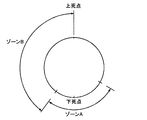
ロボットコントローラ110は、入力されるクランク角情報に基づきプレス機械105(特にその上型107)の位置を判定している。図9において、プレス機械のクランク角がロボット進入不可ゾーンAにあるときは上型107と搬入部101とが干渉するおそれがあるが、ロボット進入可能ゾーンBにあるときは干渉のおそれがない。
The robot controller 110 determines the position of the press machine 105 (particularly the upper die 107) based on the input crank angle information. In FIG. 9, when the crank angle of the press machine is in the robot inaccessible zone A, the
また、ロボットコントローラ110に入力されるロボット100の搬入アーム部101及び搬出アーム102の位置情報に基づき、搬入制御部111が搬入アーム101の作動を制御し、搬出制御部112が搬出アーム102の作動を制御する。図7において、OP1は移動開始位置、OP2はプレス干渉外位置、そしてOP3は金型上方位置である。位置OP1とOP2との間では、プレス機械105を作動させてもロボット100がプレス機械105と干渉するおそれはない。これに対して、位置OP2とOP3との間では、クランク角がロボット進入可能ゾーンBに入っているときはロボット100はプレス機械105へ進入可能であるが、ロボット進入不可能ゾーンAに入っているときは進入不可能である。
上記従来例では、プレス機械105とロボット100の同期のための制御が複雑になる。その理由は、ロボットコントローラ110において、プレス機械105からのクランク角情報と、ロボット100の搬入アーム101の位置情報とを照合しているからである。
In the conventional example, the control for synchronizing the
詳述すると、たとえばロボット100の動きがプレス機械105の動きよりも早すぎ、搬入アーム101の位置がOP2のとき、クランク角がゾーンBになっていなければ、ロボットをOP2で停止させ、クランク角がゾーンBになるまで待機させる。別言すれば、ロボット100がプレス機械105に進入するときは、その時点でのクランク角即ち上型107の位置を確認し、非干渉が確認された後でなければプレス機械105に進入できない。
More specifically, for example, when the movement of the
そのためにロボットコントローラ110での制御が複雑になっている。つまり、ロボットコントローラ110はプレス機械105のクランク角情報を受け取る部分、ロボット100の位置情報を受け取る部分、及び両者を照合する部分等が必要になる。
Therefore, the control by the robot controller 110 is complicated. That is, the robot controller 110 needs a part for receiving the crank angle information of the
本発明は上記事情に鑑みてなされたもので、簡単な制御でありながら、ワーク搬送時に往復作動式機械との干渉を確実に防止できる搬送ロボットの制御方法及び制御装置を提供することを目的とする。 The present invention has been made in view of the above circumstances, and an object of the present invention is to provide a control method and a control device for a transfer robot capable of reliably preventing interference with a reciprocating machine during workpiece transfer while being simple control. To do.
本発明の基本的な技術思想は、予め準備した、往復作動式機械の各位置に対して干渉しないロボットの各位置をテーブル化したデータテーブルに基づき搬送ロボットを作動させることである。
(1)本願の第1発明による往復作動式機械用搬送ロボットの制御方法は、請求項1に記載したように、ライン状に配置された複数のプレス機械のうち隣接する往復作動式機械間でワークを搬送ロボットで搬送するに際し、搬送ロボットの搬送部と往復作動式機械の作動部とが干渉しないように搬送ロボットの作動を制御するものである。この往復作動式機械用搬送ロボットの制御方法において、往復作動式機械によるワーク加工時における作動部の位置を逐次検出し;作動部の各位置と各位置にある作動部と干渉しない搬送部の各位置との関係が記憶されたデータテーブルに基づき、搬送ロボットの搬送部の作動を制御する。
The basic technical idea of the present invention is to operate the transport robot based on a data table prepared in advance, in which the positions of the robot that do not interfere with the positions of the reciprocating machine are tabulated.
(1) The reciprocating machine transport robot control method according to the first invention of the present application is as described in
請求項2の制御方法は、請求項1において、第1往復作動式機械からのワークの搬出時と第2往復作動式機械へのワークの搬入時とは異なるデータテーブルを使用する。
(2)本願の第2発明による往復作動式機械用搬送ロボットの制御装置は、請求項3に記載したように、隣接する往復作動式機械間で、隣接する往復作動式を結ぶ方向に移動する第1搬送部、第1搬送部に枢支され隣接する往復作動式機械を結ぶ方向に揺動する第2搬送部、及び第2搬送部の自由端に結合されワークを保持し移動するクロスバーを含む搬送ロボットによりワークを搬送する際、クロスバーと往復作動式機械の作動部とが干渉しないように搬送ロボットの作動を制御するものである。
The control method according to claim 2 uses a data table different from that at the time of unloading the workpiece from the first reciprocating machine and the loading of the workpiece into the second reciprocating machine.
(2) The control device for a reciprocating machine transport robot according to the second invention of the present application moves between adjacent reciprocating machines in a direction connecting adjacent reciprocating machines as described in claim 3. A first transport unit, a second transport unit pivotally supported by the first transport unit and swinging in a direction connecting adjacent reciprocating machines, and a crossbar coupled to the free end of the second transport unit to hold and move the workpiece When the work is transported by the transport robot including the control unit, the operation of the transport robot is controlled so that the cross bar and the operation unit of the reciprocating machine do not interfere with each other.
この往復作動式機械用搬送ロボットの制御装置は、往復作動式機械によるワーク加工時における作動部の作動位置を逐次検出する位置検出部材と、作動部の各位置と各位置にある作動部と干渉しないクロスバーの位置との関係が記憶されたデータテーブルを含み、作動部の位置情報をクロスバーの位置情報に変換する第1変換部と;データテーブルに基づき求めた位置にクロスバーが移動するように、第1搬送部及び第2搬送部を運動させる駆動手段と;から成る。 The control device for the reciprocating machine transport robot includes a position detection member that sequentially detects the operating position of the operating unit during workpiece machining by the reciprocating machine, and each position of the operating unit and the operating unit at each position interferes with each other. A first conversion unit that includes a data table in which a relationship with the position of the crossbar that is not stored is stored and that converts the position information of the operating unit into the position information of the crossbar; and the crossbar moves to the position obtained based on the data table And a driving means for moving the first transport unit and the second transport unit.
請求項4の制御装置は、請求項3において、第1搬送部及び第2搬送部はクロスバーをXY平面内で移動させ、データテーブルはクロスバーと干渉しないX方向位置及びY方向位置が記憶されている。請求項5の制御装置は、請求項4において、位置検出部材は、作動部を昇降させるために回転する回転部材の回転位相を検出することにより作動部の位置を検出する。 According to a fourth aspect of the present invention, there is provided the control device according to the third aspect, wherein the first transport unit and the second transport unit move the crossbar in the XY plane, and the data table stores the X direction position and the Y direction position that do not interfere with the crossbar. Has been. According to a fifth aspect of the present invention, in the control device according to the fourth aspect, the position detecting member detects the position of the operating portion by detecting the rotational phase of the rotating member that rotates to raise and lower the operating portion.
請求項6の制御装置は、請求項4において、データテーブルは、回転部材の所定の位相角毎にクロスバーのX軸座標及びY軸座標をテーブル化し、所定の位相角の間の位相角に対応するクロスバーのX軸座標及びY軸座標は比例計算で求める。請求項7の制御装置は、請求項3において、更にデータテーブルの位置情報を駆動手段の作動情報に変換する第2変換部を含む。 The control device according to claim 6 is the control device according to claim 4, wherein the data table tabulates the X-axis coordinate and the Y-axis coordinate of the crossbar for each predetermined phase angle of the rotating member, and sets the phase angle between the predetermined phase angles. The X-axis coordinate and Y-axis coordinate of the corresponding crossbar are obtained by proportional calculation. According to a seventh aspect of the present invention, there is provided the control device according to the third aspect, further comprising a second conversion unit for converting the position information of the data table into the operation information of the driving means.
(1)第1発明にかかる往復作動式機械用搬送ロボットの制御方法によれば、逐次検出される往復作動式機械の作動部の位置に対して干渉を生じない搬送ロボットの搬送部の位置がデータテーブルにより選出される。作動部の位置のみを検出すれば良く、搬送部の位置は検出不要である。データテーブルは、各位相角での金型の位置から干渉しない搬送部の位置を予め求めることができ、一度準備したデータテーブルを繰り返し使用できる。その結果、搬送ロボットの搬送部の作動の制御が簡単になる。 (1) According to the control method for the reciprocating machine transport robot according to the first aspect of the present invention, the position of the transport section of the transport robot that does not interfere with the position of the operating section of the reciprocating machine that is sequentially detected is determined. Selected by data table. It is only necessary to detect the position of the operating unit, and the position of the transport unit is not required to be detected. The data table can determine in advance the position of the conveyance unit that does not interfere with the position of the mold at each phase angle, and the data table once prepared can be used repeatedly. As a result, the control of the operation of the transfer unit of the transfer robot is simplified.
請求項2の制御方法によれば、ある搬送ロボットと、この搬送ロボットがワークを搬出する第1往復作動式機械の作動部、及びこの搬送ロボットがワークを搬入する第2往復作動式機械の作動部との干渉が防止できる。
(2)第2発明にかかる往復作動式機械用搬送ロボットの制御装置によれば、第1往復作動式機械と第2往復作動式機械との間でワークを搬送するために移動する搬送ロボットのクロスバーの作動を、データテーブルに基づき制御することにより、クロスバーと第1往復作動式機械及び第2往復作動式機械の作動部との干渉が防止できる。データテーブルの使用による効果については制御方法の欄で説明した。このクロスバーを含む搬送ロボットは、コンパクトな構造でありながら、第1往復作動式機械からのワークの搬出及び第2往復作動式機械へのワークの搬入が行える。
According to the control method of claim 2, a certain transfer robot, an operation unit of the first reciprocating machine that carries the workpiece by the transfer robot, and an operation of the second reciprocating machine that carries the workpiece by the transfer robot. Interference with the part can be prevented.
(2) According to the control device for the reciprocating machine transport robot according to the second aspect of the invention, the transport robot that moves to transport the workpiece between the first reciprocating machine and the second reciprocating machine. By controlling the operation of the crossbar based on the data table, it is possible to prevent interference between the crossbar and the operating portion of the first reciprocating machine and the second reciprocating machine. The effect of using the data table was explained in the control method column. Although the transfer robot including the crossbar has a compact structure, it can carry out the work from the first reciprocating machine and carry the work into the second reciprocating machine.
請求項4の制御装置によれば、XY平面内においてクロスバーを作動部と干渉することなく移動させることができる。請求項5の制御装置によれば、回転部材の位相の検出により作動部の位置が検出でき、検出が容易でしかも正確に行える。請求項6の制御装置によれば、回転部材の位置がより正確に検出でき、それによりクロスバーはより確実に作動部と干渉しない軌跡に沿って移動されることになる。請求項7の制御装置によれば、駆動手段により第1搬送部及び第2搬送部が確実に駆動される。 According to the control device of the fourth aspect, the crossbar can be moved in the XY plane without interfering with the operating portion. According to the control device of the fifth aspect, the position of the operating portion can be detected by detecting the phase of the rotating member, and the detection can be performed easily and accurately. According to the control device of the sixth aspect, the position of the rotating member can be detected more accurately, whereby the crossbar is moved along a trajectory that does not interfere with the operating portion more reliably. According to the control device of the seventh aspect, the first transport unit and the second transport unit are reliably driven by the driving means.
<往復作動式機械>
往復作動する往復作動式機械としてはプレス機械、射出成型機及び旋盤等が挙げられ、本発明はこれらのすべてに適用できる。プレス機械では移動金型(通常上型)が作動部に相当する。射出成型機では移動金型が作動部に相当し、搬送ロボットは隣接する第1射出成型機と第2射出成型機との間でワークを搬送する。旋盤では刃物保持部が作動部に相当し、搬送ロボットは隣接する第1旋盤と第2旋盤との間でワークを搬送する。なお、以下の説明はプレス機械を中心に行う。
<Reciprocating machine>
Examples of the reciprocating machine that reciprocates include a press machine, an injection molding machine, and a lathe, and the present invention can be applied to all of them. In the press machine, the moving mold (usually the upper mold) corresponds to the operating part. In the injection molding machine, the moving mold corresponds to the operating portion, and the transfer robot transfers the workpiece between the adjacent first injection molding machine and second injection molding machine. In the lathe, the blade holding portion corresponds to the operating portion, and the transfer robot transfers the workpiece between the adjacent first lathe and second lathe. The following description will be focused on the press machine.
プレス機械としては、固定部、可動部及び駆動部を有する汎用のプレス機械を使用できる。固定部に下型(ダイ)が、固定部に対して昇降可能な可動部に上型(パンチ)が固定されている。駆動部は例えばメインギアの回転をクランクによりスライドの上下運動(昇降運動)に変換する。ワークを順次加工する複数のプレス機械(第1プレス機械、第2プレス機械、第3プレス機械・・)が一つのプレスラインを構成する。第1プレス機械が第1加工を行い、第2プレス機械が第1加工に引き続く第2加工を行い、第3プレス機が第2加工に引き続く第3加工を行う。 As the press machine, a general-purpose press machine having a fixed part, a movable part and a drive part can be used. A lower die (die) is fixed to the fixed portion, and an upper die (punch) is fixed to the movable portion that can be raised and lowered relative to the fixed portion. For example, the drive unit converts the rotation of the main gear into a vertical movement (lifting movement) of the slide by a crank. A plurality of press machines (first press machine, second press machine, third press machine,...) That sequentially process the workpiece constitute one press line. The first press machine performs the first process, the second press machine performs the second process subsequent to the first process, and the third press machine performs the third process subsequent to the second process.
プレスラインにはタンデムプレスライン及びトランスファプレスラインが含まれる。なお、同じ構成の複数のプレスラインを互いに平行に配置する場合、複数の第1プレス機械は同じ第1加工を行い、複数の第2プレス機械は同じ第2加工を行う。
<搬送ロボット>
本発明の搬送ロボットは隣接するプレス機械等往復作動式機械間でワークを搬送する。隣接するプレス機械間とは、第1プレスラインの第1プレス機械と第2プレス機との間、第2プレス機械と第3プレス機との間、・・を意味する。搬送ロボットはワークを二次元座標(XY平面)又は三次元座標(XYZ空間)で搬送する。さらに、手首の回転等に対応した六次元座標(XYZαβγ)で搬送することもできる。
The press line includes a tandem press line and a transfer press line. When a plurality of press lines having the same configuration are arranged in parallel to each other, the plurality of first press machines perform the same first processing, and the plurality of second press machines perform the same second processing.
<Transport robot>
The transfer robot of the present invention transfers a workpiece between reciprocating machines such as adjacent press machines. Between adjacent press machines means between the first press machine and the second press machine of the first press line, between the second press machine and the third press machine,. The transfer robot transfers the workpiece in two-dimensional coordinates (XY plane) or three-dimensional coordinates (XYZ space). Furthermore, it can also be conveyed by six-dimensional coordinates (XYZαβγ) corresponding to wrist rotation or the like.
代表的な搬送ロボットは、隣接するプレス機械の一側に配置された一側駆動部と、他側に配置された他側駆動部と、隣接するプレス機械間に延び両駆動部を結びワークの保持部を備えたクロスバーとを含む。クロスバーが第1プレス機械と第2プレス機械との間を往復動し、第1プレス機械から搬出したワークを第2プレス機械に搬入する。つまり、クロスバーは第1プレス機械の金型に対して進入及び退出するとともに、第2プレス機械の金型に対して進入及び退出する。
<搬送ロボットの制御>
制御装置は少なくとも、金型等作動部の位置検出部、データテーブルを含む第1変換部及び駆動手段を含み、更に第2変換部を含むことができる。金型(上型)の位置を検出する位置検出部は、例えばメインギアの回転位相又はクランクの角度(クランク角)を検出すれば良い。
A typical transfer robot includes a one-side drive unit arranged on one side of an adjacent press machine, an other-side drive unit arranged on the other side, and extends between adjacent press machines to connect both drive units to each other. And a cross bar provided with a holding portion. The cross bar reciprocates between the first press machine and the second press machine, and the work carried out from the first press machine is carried into the second press machine. That is, the cross bar enters and exits the mold of the first press machine and enters and exits the mold of the second press machine.
<Control of transfer robot>
The control device includes at least a position detection unit of an operation unit such as a mold, a first conversion unit including a data table, and a driving unit, and may further include a second conversion unit. The position detector that detects the position of the mold (upper mold) may detect, for example, the rotation phase of the main gear or the crank angle (crank angle).
第1変換部は位置検出部で検出される金型(上型)の位置情報を搬送ロボット(特にクロスバー)の位置情報に変換するものであり、上型の位置情報とクロスバーの位置情報とがテーブル化されRAM等に格納されたデータテーブルを含む。上型の位置検出については上述した。例えば、メインギアの一回転によりスライドが一往復する場合、位相角は一定値毎(例えば1°)に選定し、それに対するクロスバーのX座標、Y座標を決める。一定値と一定値との間の位相角に対するクロスバーのX座標、Y座標は比例計算で求める。 The first conversion unit converts the position information of the mold (upper mold) detected by the position detection unit into the position information of the transfer robot (particularly the crossbar). The position information of the upper mold and the position information of the crossbar And a data table stored in a RAM or the like. The position detection of the upper mold has been described above. For example, when the slide makes one reciprocation by one rotation of the main gear, the phase angle is selected for every fixed value (for example, 1 °), and the X coordinate and Y coordinate of the crossbar are determined. The X coordinate and Y coordinate of the crossbar with respect to the phase angle between the constant value and the constant value are obtained by proportional calculation.
第1プレス機械と第2プレス機械との間の搬送ロボットの作動は両者の作動との関係で決めることが必要である。但し、第1プレス機械と第2プレス機械とは下型と上型との間隔や上型の昇降ストローク等が異なるので、第1プレス機械と搬送ロボットとの関係と、第2プレス機械と搬送ロボットとの関係は別々のデータテーブルで制御する。なお、第2変換部は、クロスバーの位置情報をクロスバーを移動させる駆動手段即ち搬送部及びモータ等の作動情報に変換するものである。
<関連事項>
本発明は直接的にはプレス機械等の往復作動式機械と搬送ロボットとの干渉を防止するための搬送部の作動に関するが、あるプレス機械の搬入側の搬送ロボットと搬出側の搬送ロボットとの干渉防止にも関連する。搬入側の搬送ロボットとプレス機械との非干渉、及び搬出側の搬送ロボットとプレスロボットとの非干渉が、搬入側の搬送ロボットと搬出側の搬送ロボットとの干渉につながるからである。
It is necessary to determine the operation of the transfer robot between the first press machine and the second press machine in relation to the operation of both. However, the first press machine and the second press machine are different in the distance between the lower die and the upper die, the lifting stroke of the upper die, etc., and the relationship between the first press machine and the transfer robot, the second press machine and the transfer The relationship with the robot is controlled by a separate data table. The second conversion unit converts the crossbar position information into driving information for moving the crossbar, that is, operation information about the conveyance unit, the motor, and the like.
<Related matters>
Although the present invention relates directly to the operation of a transfer unit for preventing interference between a reciprocating machine such as a press machine and a transfer robot, there is a difference between a transfer robot on a carry-in side and a transfer robot on a carry-out side of a press machine. Also related to interference prevention. This is because non-interference between the carry-in transfer robot and the press machine and non-interference between the carry-out transfer robot and the press robot lead to interference between the carry-in transfer robot and the carry-out transfer robot.
また、プレス機械の位相角に応じた位置へ搬送ロボットが動くため、プレス機械のストロークサイクルを早くすれば搬送ロボットは速く動作し、遅くすれば遅く動作する。プレス機械に干渉しないように搬送ロボットの動作スピードやタイミングを別に制御しなくても、自動的に簡単に制御できる。 Further, since the transfer robot moves to a position corresponding to the phase angle of the press machine, the transfer robot operates faster if the stroke cycle of the press machine is made faster, and slower if it is made slower. It can be automatically and easily controlled without controlling the operation speed and timing of the transfer robot so as not to interfere with the press machine.
以下、本発明の実施例を添付図面を参照しつつ説明する。
<第1実施例>
(構成)
a.全体
図1に示すように、直線状に並置された複数のプレス機械10−1A、10−1B、10−1C・・が第1タンデムプレスラインを構成し、一つのワークを順次加工する。別言すれば、一つのワークは複数のプレス機械で順次加工される。そして、隣接するプレス機械10−1A、10−1B、10−1C・・間において搬送ロボット30がワークを搬送する。
b.プレス機械
複数のプレス機械10−1A、10−1B、10−1C・・は金型の形状、大きさ及びストロークが異なる他は、基本的同じ構成を持つ。例えば中央のプレス機械10‐1Bは図2に示すように、固定部11、可動部17、駆動部21及び位相角検出器25を等を含む。
Embodiments of the present invention will be described below with reference to the accompanying drawings.
<First embodiment>
(Constitution)
a. Overall As shown in FIG. 1, a plurality of press machines 10-1A, 10-1B, 10-1C,... Arranged in a straight line constitutes a first tandem press line, and sequentially processes one workpiece. In other words, one workpiece is sequentially processed by a plurality of press machines. And the
b. Press machines The plurality of press machines 10-1A, 10-1B, 10-1C,... Have basically the same configuration except that the shape, size and stroke of the mold are different. For example, the central press machine 10-1B includes a fixed
詳述すると、固定部11は基部(ボルスタ)12、基部12に立設された柱状部(アプライト)13、柱状部の上端に固定された天井部(クラウン)14、及び基部12の上面に固定され所定の加工面を備えた下型15を含む。可動部17は上下動可能なスライド18と、スライドの下面に固定され所定の加工面を備えた上型19とを含む。駆動部21は駆動源(不図示)により回転されるメインギア22と、メインギア22の回転をスライド18の上下運動に変換するクランク機構23とを含む。メインギア22に隣接して配置された位相角検出器25がメインギア22の回転位相検出している。
c.搬送ロボット
図1,図3に示すように、搬送ロボット30は隣接するプレス機械10−1Aと10−1Bとの間に配置され、左方のプレス機械10−1Aから搬出したワークを右方のプレス機10‐1Bに搬入する。プレス機械10−1A及び10‐1Bの一側に位置する一側駆動部31、プレス機械の他側に位置する他側駆動部41、及び隣接するプレス機械10‐1Aと10‐1Bとの間の空間を延び両方の駆動部を結合するクロスバー45を含む。一側駆動部は案内部材32、走行部材34、二つの揺動部材36,38を有する。他側駆動部41はプレス機械10に対して一側駆動部31と対称な構成を持つ。
More specifically, the fixing
c. Transport Robot As shown in FIGS. 1 and 3, the
一側駆動部31の案内部材32は隣接するプレス機械間に固定配置され所定長さを持つ。案内部材32に搭載された走行部材34は、その一端に備えたモータ35に駆動され案内部材32上を往復直線直線運動可能である。第1揺動部材36の一端が走行部材34に枢支され、モータ37に駆動されてワークの搬送方向に揺動可能である。第1揺動部材36の他端に第2揺動部材38の一端が枢支され、モータ39に駆動されてワークの搬送方向に揺動可能である。その一端が第2揺動部材38の他端に結合されたクロスバー45の他端は他側駆動部41の第2揺動部材38の他端に結合されている。クロスバー45はワークwを保持するための保持部46をその中間部に備えている。
The
クロスバー45は案内部材32に対する走行部材34の走行(直線移動)、走行部材に対する第1揺動部材36の揺動、及び第1揺動部材に対する第2揺動部材38の揺動の合成により決まる軌跡aからfに沿って移動する。但し、その長手方向(図3の紙面と垂直な方向)には移動しないので、その運動は案内部材32を含む平面即ち垂直面内における二次元的な運動である。よって、クロスバー45の位置は二次元座標で表すことができる。
d.制御装置
搬送ロボットの作動を制御する制御装置50を図4に示す。制御装置50は位相角入力部51、第1変換部52、第2変換部56及びアンプ部58を含む。位相角入力部51は位相角検出器25からメインギア22の位相角を入力される。位相角信号をロボット位置信号に変換する第1変換部52は、内挿演算部53とデータテーブル54とを含む。
The
d. Control Device FIG. 4 shows a
データテーブル54はメインギア22の位相角0°から360°に対して干渉しない搬送ロボットのクロスバー45のX軸方向位置(X座標)及びY軸方向位置(Y座標)が
1°毎にテーブル化されたもので、RAM内に記憶されている。例えば、プレス機械10−1Aの位相角が175°のとき、搬送ロボット30のクロスバー45のX軸方向位置がx1で、Y軸方向位置がy1であれば、上型28とクロスバー45とは干渉するおそれがない。なお、この位相角とX軸方向位置及びY軸方向位置との関係は、予めプレス機械の各位相角でのスライドの位置と上型の寸法から干渉しない最短の位置を計算して求めたものである。
The data table 54 is a table in which the X-axis direction position (X coordinate) and the Y-axis direction position (Y coordinate) of the
内挿演算部53はデータテーブル54に記憶されていない位相角に対応するX軸方向位置及びY軸方向位置を、記憶されている位相角に基づき算出するものである。例えば、位相角175°に対するX軸方向位置がx1で、位相角176°に対するX軸方向位置がx2のとき、位相角175.5に対するX軸方向位置を(x1+x2)/2から求める。
(作用)
次に、この実施例の作用即ち制御方法を説明する。図3において搬送ロボットのクロスバー45は、一側駆動部31及び他側駆動部41の駆動により第1プレス機械10A−1と第2プレス機械10‐1Bとの間軌跡aからfに沿って移動され、それに伴いワークwを搬送する。即ち、主に案内部材32に対する走行部材34の左方向への走行(直線移動)によりクロスバー45が第1プレス機械10‐1Aに接近する。
a.第1プレス機械へのクロスバーの進入及び退出
第1プレス機械10−1Aの上型19の上昇後(案内部材に対する走行部材の走行と、)fで示すように、クロスバー45が第1プレス機械の下型15と上型19との間の空間に進入し、第1プレス機械10−1Aによる加工が終わったワークを保持部46で保持する。クロスバー45は主に走行部材34に対する第1揺動部材36の揺動と、第1揺動部材36に対する第2揺動部材38の揺動との合成運動により、aで示す軌跡に沿って移動される。
The
(Function)
Next, the operation, that is, the control method of this embodiment will be described. In FIG. 3, the
a. After the
具体的に説明すると、クロスバー45の第1プレス機械10−1Aへの進入時、一側駆動部31及び他側駆動部41は第1プレス機械10−1Aの位置情報に基づき、クロスバー45を駆動する。つまり、位相角検出器25で検出されるメインギア22の位相角度(即ち上型19の位置情報)が第1変換器部52によりクロスバー45の位置情報に変換される。データテーブル54において位相角に応じたX座標及びY座標が選出され、その結果が第2変換部56により搬送ロボットの位置情報に変換される。これに基づくモータ35の駆動により走行部材34が走行しモータ37の駆動により第1揺動部材36が揺動し、モータ39の駆動により第2揺動部材38が揺動する。こうして、クロスバー45はfで示す軌跡に沿って下型15と上型19との間に進入する。
More specifically, when the
そして、上型19が下降する前に、クロスバー45は主に走行部材34に対する第1揺動部材36の揺動と、第1揺動部材36に対する第2揺動部材38の揺動との合成運動により、aで示すように、下型15と上型19との間の空間から退出する。なお、クロスバー45の第1プレス機械10−1Aからの退出時も、一側駆動部31及び他側駆動部41は第1プレス機械10−1Aの位置情報に基づき、クロスバー45を駆動する。
Before the
その後、主に案内部材32に対する走行部材34の右方向への走行(直線移動)によりbで示すようにクロスバー45が第1プレス機械から取り出したワークを第2プレス機械10−1Bに搬送する。
b.第2プレス機械へのクロスバーの進入及び退出
第2プレス機械10−1Bの上型19の下降前、走行部材34の走行と第1揺動部材36の揺動と第2揺動部材38の揺動との合成運動により、cで示すように、クロスバー45が第2プレス機械10‐1Bの下型15と上型19との間の空間に進入し、保持部46で保持したワークwを両型間の空間に置く。そして、上型19が下降する前に、走行部材34の走行と第1揺動部材36の揺動と第2揺動部材38の揺動との合成運動により、dで示すように、クロスバー45は下型15と上型19との間の空間から退出する。このクロスバー45の第2プレス機械10‐1Bへの進入時、及び第2プレス機械10‐1Bからの退出時も、一側駆動部31及び他側駆動部41は第2プレス機械10‐1Bの位置情報に基づき、クロスバー45を駆動する。
Thereafter, the work taken by the
b. Before and after the
その後、主に案内部材32に対する走行部材34の左方向への走行(直線移動)によりeで示すようにクロスバー45は左方に移動する。
(効果)
この実施例によれば、以下の効果が得られる。
a.クロスバー45と上型19との干渉の回避に関して
第1に、搬送ロボット30による第1プレス機械10−1Aからのワークwの搬出時に、クロスバー45と上型19との干渉が確実に回避できる。メインギア22の位相角度即ち上型19の位置と、クロスバー45の位置(X座標及びY座標)とが干渉しない関係を記憶したデータテーブル54に基づき、一側駆動部31及び他側駆動部41のモータ35,37及び39を駆動して、クロスバー45の位置を決めているからである。
Thereafter, the
(effect)
According to this embodiment, the following effects can be obtained.
a. Regarding the avoidance of the interference between the
例えば、クロスバー45の第1プレス機械10−1Aへの進入時に、何らかの理由により上型19が所定位置まで上昇していない場合、クロスバー45が通常通り進入すると上型19と干渉する。この実施例では、データテーブル54に基づき、通常位置よりも下方位置にある上型28に対して干渉しないクロスバー45の位置(通常位置に比べて上型19からより離れた位置)が決定され、モータ35,37及び39はクロスバー45をその安全な位置までしか移動させない。
For example, when the
第2に、内挿演算部53及びデータテーブル54により、上型19の位置とクロスバー45との位置とを高い精度で対応させることができる。
b.制御装置50による搬送ロボット30の制御に関して
制御装置50の構成が簡単で、制御も簡単になる。制御装置に必須なのは位相角入力部51、第1変換部52及び第2変換部56である。第1変換部52及び第2変換部56は位相角信号→ロボット位置信号→モータ位置信号に変換するのみで良い。検出される位相角が所定値になっていないとき即ち上型19が所定位置まで上昇していないときは、それに対応した位置にクロスバー45が自動的に移動される。その際、クロスバー45の位相を検出するセンサ等は不要である。
c.プレス機械、搬送ロボットの作動サイクルに関して
第1に、搬送ロボットが第1プレス機械10‐1Aと第2プレス機械10‐1Bとの間でワークwを搬送するのに要するサイクルタイムも短縮できる。クロスバー45は上型19が干渉のおそれがなくなった位置に達した直後に第1プレス機械10‐1A内に進入でき、上型19との干渉を避けるための待機は不要だからである。
Secondly, the position of the
b. Regarding the control of the
c. Regarding the operation cycle of the press machine and the transfer robot First, the cycle time required for the transfer robot to transfer the workpiece w between the first press machine 10-1A and the second press machine 10-1B can be shortened. This is because the
第2に、プレス機械の加工サイクルを早くしても即ちプレス機械の加工サイクルに関係なく、搬送ロボットはプレス機械に干渉することなくワークを搬送できるため、プレスラインのサイクルタイムを短縮できる。 Secondly, even if the processing cycle of the press machine is accelerated, that is, regardless of the processing cycle of the press machine, the transfer robot can transfer the workpiece without interfering with the press machine, so that the cycle time of the press line can be shortened.
第3に、プレス機械のサイクルを逆転させた場合でも、搬送ロボットと干渉することなく同期できる。即ち、ワークの搬入ミスによりプレス機械のスライドが停止した場合、その状態からスライドを逆転させ、搬入ミスしたワークの位置を修正して、再度加工する。従来は、搬送ロボットを単独で動かし退避させた後プレス機械を逆転させるが、この実施例ではこの操作を行うことなく、プレス機械を逆転させれば、搬送ロボットはその位相角に追従して動作する(同期する)。
<第2実施例>
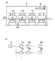
本発明がトランスファプレスに適用された実施例を図5に示す。図5(a)に示すように、プレス機械10は並置された各工程のプレス部10A、10B、10C・・から成り、各プレス部のスライド18を一つの駆動部21で駆動するようになっている。そして、このようなプレス機10が複数平行に並置されている。隣接するプレス部10Aと10Bとの間、プレス部10Bと10Cとの間でのワークの搬送を第1実施例と同様の搬送ロボット30A、30B・・で行っている。例えば、第1工程のプレス部10Aと第2工程のプレス部10Bとの間では第2搬送ロボット30Bがワークを搬送する。
Thirdly, even if the cycle of the press machine is reversed, it can be synchronized without interfering with the transfer robot. That is, if the slide of the press machine stops due to a workpiece loading error, the slide is reversed from that state, the position of the workpiece that has been loaded incorrectly is corrected, and the workpiece is processed again. Conventionally, after the transfer robot is moved and retracted alone, the press machine is reversed, but in this embodiment, if the press machine is reversed without performing this operation, the transfer robot follows the phase angle. Yes (synchronize).
<Second embodiment>
An embodiment in which the present invention is applied to a transfer press is shown in FIG. As shown in FIG. 5 (a), the press machine 10 includes
すべての搬送ロボットの作動を駆動部21に取り付けた検出器25で制御している。そのために、図5(b)に示すように、例えばプレス部10A、10B・・の金型の位置が検出器25に入力され、検出器25はこの入力情報に基づき、搬送ロボット30A、30B・・を同期させて運転する。その他のプレス機((不図示))と搬送ロボット50A、50B・・、搬送ロボット51A、51B・・との関係についても同様である。
The operations of all the transport robots are controlled by a
この第2実施例においても、上記第1実施例と同様の効果が得られる。加えて、搬送速度が早くできる等、トランスファプレスに特有の効果が得られる。 In the second embodiment, the same effect as in the first embodiment can be obtained. In addition, an effect peculiar to the transfer press, such as a high conveying speed, can be obtained.
10−1A:第1プレス機械 10−1B:第2プレス機械
11:固定部 15:下型
17:可動部 19:上型
21:駆動部 25:位相各検出器
30:搬送ロボット 31:一側駆動部
34:第1搬送部 36、38:第2搬送部
41:他側駆動部 45:クロスバー
50:制御装置 52:第1変換部
54:データテーブル 56:第2変換部
10-1A: 1st press machine 10-1B: 2nd press machine 11: Fixed part 15: Lower mold 17: Movable part 19: Upper mold 21: Drive part 25: Each phase detector 30: Conveying robot 31: One side Drive unit 34:
Claims (7)
前記往復作動式機械によるワーク加工時における前記作動部の位置を逐次検出し、
前記作動部の各位置と該各位置にある該作動部と干渉しない該搬送部の各位置との関係が記憶されたデータテーブルに基づき、前記搬送ロボットの搬送部の作動を制御する、
ことを特徴とする往復作動式機械用搬送ロボットの制御方法。 When transferring workpieces between adjacent reciprocating machines among a plurality of reciprocating machines arranged in a line with a transfer robot, the transfer part of the transfer robot and the operating part of the reciprocating machine should not interfere with each other. A control method for controlling the operation of a transfer robot,
Sequentially detecting the position of the working part during workpiece machining by the reciprocating machine;
Controlling the operation of the transfer unit of the transfer robot based on a data table storing the relationship between each position of the operation unit and each position of the transfer unit that does not interfere with the operation unit at each position;
A control method for a reciprocating machine transfer robot.
前記往復作動式機械によるワーク加工時における前記作動部の作動位置を逐次検出する位置検出部材と、
前記作動部の各位置と該各位置にある該作動部と干渉しない該クロスバーの位置との関係が記憶されたデータテーブルを含み、該作動部の位置情報を該クロスバーの位置情報に変換する第1変換部と、
前記データテーブルに基づき求めた位置に前記クロスバーが移動するように、前記第1搬送部及び第2搬送部を運動させる駆動手段と、
から成ることを特徴とする往復作動式機械用搬送ロボットの制御装置。 A first transport unit that moves in a direction connecting adjacent reciprocating machines between adjacent reciprocating machines, and a second that pivots on the first transport unit and swings in a direction connecting adjacent reciprocating machines. When a workpiece is conveyed by a conveyance robot including a conveyance unit and a crossbar coupled to the free end of the second conveyance unit and holding and moving the workpiece, the crossbar and the operation unit of the reciprocating machine do not interfere with each other. A control device for controlling the operation of the transfer robot,
A position detection member for sequentially detecting the operation position of the operation unit during workpiece machining by the reciprocating machine;
Including a data table storing a relationship between each position of the operating unit and the position of the crossbar that does not interfere with the operating unit at each position, and converts the position information of the operating unit into position information of the crossbar A first converter to
Driving means for moving the first transport unit and the second transport unit so that the crossbar moves to a position determined based on the data table;
A control device for a reciprocating machine transfer robot characterized by comprising:
Priority Applications (1)
| Application Number | Priority Date | Filing Date | Title |
|---|---|---|---|
| JP2004023726A JP2005216112A (en) | 2004-01-30 | 2004-01-30 | Control method and controller of carrying robot for reciprocating machine |
Applications Claiming Priority (1)
| Application Number | Priority Date | Filing Date | Title |
|---|---|---|---|
| JP2004023726A JP2005216112A (en) | 2004-01-30 | 2004-01-30 | Control method and controller of carrying robot for reciprocating machine |
Related Child Applications (1)
| Application Number | Title | Priority Date | Filing Date |
|---|---|---|---|
| JP2011062843A Division JP2011143474A (en) | 2011-03-22 | 2011-03-22 | Method and device for controlling conveying robot for reciprocating operation type machine |
Publications (1)
| Publication Number | Publication Date |
|---|---|
| JP2005216112A true JP2005216112A (en) | 2005-08-11 |
Family
ID=34906646
Family Applications (1)
| Application Number | Title | Priority Date | Filing Date |
|---|---|---|---|
| JP2004023726A Pending JP2005216112A (en) | 2004-01-30 | 2004-01-30 | Control method and controller of carrying robot for reciprocating machine |
Country Status (1)
| Country | Link |
|---|---|
| JP (1) | JP2005216112A (en) |
Cited By (8)
| Publication number | Priority date | Publication date | Assignee | Title |
|---|---|---|---|---|
| WO2006132201A1 (en) * | 2005-06-06 | 2006-12-14 | Ihi Corporation | Work conveying device, control method for work conveying device, and press line |
| WO2009014131A1 (en) * | 2007-07-23 | 2009-01-29 | Ihi Corporation | Simulation method |
| JP2013003693A (en) * | 2011-06-14 | 2013-01-07 | Mazda Motor Corp | Design support method and design support system of component manufacturing line |
| JP2013163203A (en) * | 2012-02-10 | 2013-08-22 | Honda Motor Co Ltd | Changing method of transfer motion |
| JP2018069336A (en) * | 2016-10-25 | 2018-05-10 | シーメンス アクチエンゲゼルシヤフトSiemens Aktiengesellschaft | Optimization method of movement profile, preparation method of the movement profile, control device, equipment, and computer program |
| JP2021005126A (en) * | 2019-06-25 | 2021-01-14 | ファナック株式会社 | Press-work simulating device |
| CN114030222A (en) * | 2021-11-04 | 2022-02-11 | 温州大学 | Visual multi-machine coordination track optimization method and system for press line |
| US11565409B2 (en) | 2019-06-25 | 2023-01-31 | Fanuc Corporation | Robot programming system |
-
2004
- 2004-01-30 JP JP2004023726A patent/JP2005216112A/en active Pending
Cited By (15)
| Publication number | Priority date | Publication date | Assignee | Title |
|---|---|---|---|---|
| WO2006132201A1 (en) * | 2005-06-06 | 2006-12-14 | Ihi Corporation | Work conveying device, control method for work conveying device, and press line |
| US7873431B2 (en) | 2005-06-06 | 2011-01-18 | Ihi Corporation | Workpiece transfer apparatus, control method for workpiece transfer apparatus, and press line |
| WO2009014131A1 (en) * | 2007-07-23 | 2009-01-29 | Ihi Corporation | Simulation method |
| JP2009022996A (en) * | 2007-07-23 | 2009-02-05 | Ihi Corp | Simulation method |
| JP2013003693A (en) * | 2011-06-14 | 2013-01-07 | Mazda Motor Corp | Design support method and design support system of component manufacturing line |
| JP2013163203A (en) * | 2012-02-10 | 2013-08-22 | Honda Motor Co Ltd | Changing method of transfer motion |
| JP2018069336A (en) * | 2016-10-25 | 2018-05-10 | シーメンス アクチエンゲゼルシヤフトSiemens Aktiengesellschaft | Optimization method of movement profile, preparation method of the movement profile, control device, equipment, and computer program |
| US11173680B2 (en) | 2016-10-25 | 2021-11-16 | Siemens Aktiengesellschaft | Method for optimizing movement profiles, method for providing movement profiles, control device, system and computer program product |
| JP7031949B2 (en) | 2016-10-25 | 2022-03-08 | シーメンス アクチエンゲゼルシヤフト | How to optimize roaming profiles, how to prepare roaming profiles, controls, equipment and computer programs |
| JP2021005126A (en) * | 2019-06-25 | 2021-01-14 | ファナック株式会社 | Press-work simulating device |
| US11565409B2 (en) | 2019-06-25 | 2023-01-31 | Fanuc Corporation | Robot programming system |
| US11673262B2 (en) | 2019-06-25 | 2023-06-13 | Fanuc Corporation | Press working simulator |
| JP7316111B2 (en) | 2019-06-25 | 2023-07-27 | ファナック株式会社 | Press working simulation device |
| CN114030222A (en) * | 2021-11-04 | 2022-02-11 | 温州大学 | Visual multi-machine coordination track optimization method and system for press line |
| CN114030222B (en) * | 2021-11-04 | 2023-12-01 | 温州大学 | Visual stamping line multi-machine coordination track optimization method and system |
Similar Documents
| Publication | Publication Date | Title |
|---|---|---|
| CN104759894A (en) | Machining production line for sheet metal | |
| TWI380899B (en) | Servopress apparatus and its control method | |
| CN107876613B (en) | Workpiece processing production line and method combining pipe end processing and pipe bending processing | |
| JP2010094695A (en) | Workpiece conveying apparatus | |
| JP4751415B2 (en) | Press brake | |
| JP2005216112A (en) | Control method and controller of carrying robot for reciprocating machine | |
| JPH0437424A (en) | Device and method for controlling operation of machine line | |
| CN207494280U (en) | A kind of workpiece process for producing line for combining pipe end processing and bend pipe processing | |
| JP5834515B2 (en) | Design support method and design support system for parts production line | |
| JP2011143474A (en) | Method and device for controlling conveying robot for reciprocating operation type machine | |
| JP2006281269A (en) | Workpiece-conveying device | |
| CN204657958U (en) | A kind of sheet metal machining production line | |
| JP5861159B2 (en) | Turret forging equipment | |
| JPH08216073A (en) | Robot for work carrying-in/carrying-out work | |
| WO2010035650A1 (en) | Method for setting operation condition of press line | |
| JP5218581B2 (en) | Work processing system and method for manufacturing processed product | |
| JP4542862B2 (en) | Drive command generation device for work transfer device | |
| JP3423149B2 (en) | Work feeder control device | |
| KR101536097B1 (en) | Tandem press system | |
| JP7458629B2 (en) | Progressive press conveying device, progressive press device, and method of manufacturing metal products | |
| JPH09155681A (en) | Method and device for controlling conveying device in production line | |
| JP3423141B2 (en) | Synchronization loss recovery device | |
| JP2009039727A (en) | Workpiece transporting method of multi-process press machine, and its apparatus | |
| JP2007069239A (en) | Automatic press system | |
| JP2006130518A (en) | Conveying apparatus, conveying robot and press line |
Legal Events
| Date | Code | Title | Description |
|---|---|---|---|
| A621 | Written request for application examination |
Free format text: JAPANESE INTERMEDIATE CODE: A621 Effective date: 20060929 |
|
| A131 | Notification of reasons for refusal |
Free format text: JAPANESE INTERMEDIATE CODE: A131 Effective date: 20081021 |
|
| A977 | Report on retrieval |
Free format text: JAPANESE INTERMEDIATE CODE: A971007 Effective date: 20081023 |
|
| A521 | Written amendment |
Free format text: JAPANESE INTERMEDIATE CODE: A523 Effective date: 20081219 |
|
| A02 | Decision of refusal |
Free format text: JAPANESE INTERMEDIATE CODE: A02 Effective date: 20090310 |
|
| A521 | Written amendment |
Free format text: JAPANESE INTERMEDIATE CODE: A523 Effective date: 20090420 |
|
| A521 | Written amendment |
Free format text: JAPANESE INTERMEDIATE CODE: A821 Effective date: 20090410 |
|
| A911 | Transfer to examiner for re-examination before appeal (zenchi) |
Free format text: JAPANESE INTERMEDIATE CODE: A911 Effective date: 20090515 |
|
| A912 | Re-examination (zenchi) completed and case transferred to appeal board |
Free format text: JAPANESE INTERMEDIATE CODE: A912 Effective date: 20090731 |
|
| A521 | Written amendment |
Free format text: JAPANESE INTERMEDIATE CODE: A523 Effective date: 20101115 |