JP2005206254A - Apparatus for opening tube bag and manufacturing method for tube bag which is opened with apparatus beforehand and re-closed - Google Patents
Apparatus for opening tube bag and manufacturing method for tube bag which is opened with apparatus beforehand and re-closed Download PDFInfo
- Publication number
- JP2005206254A JP2005206254A JP2005016181A JP2005016181A JP2005206254A JP 2005206254 A JP2005206254 A JP 2005206254A JP 2005016181 A JP2005016181 A JP 2005016181A JP 2005016181 A JP2005016181 A JP 2005016181A JP 2005206254 A JP2005206254 A JP 2005206254A
- Authority
- JP
- Japan
- Prior art keywords
- blade
- bag
- tube
- piece
- opening
- Prior art date
- Legal status (The legal status is an assumption and is not a legal conclusion. Google has not performed a legal analysis and makes no representation as to the accuracy of the status listed.)
- Withdrawn
Links
Images


Classifications
-
- B—PERFORMING OPERATIONS; TRANSPORTING
- B05—SPRAYING OR ATOMISING IN GENERAL; APPLYING FLUENT MATERIALS TO SURFACES, IN GENERAL
- B05C—APPARATUS FOR APPLYING FLUENT MATERIALS TO SURFACES, IN GENERAL
- B05C17/00—Hand tools or apparatus using hand held tools, for applying liquids or other fluent materials to, for spreading applied liquids or other fluent materials on, or for partially removing applied liquids or other fluent materials from, surfaces
- B05C17/005—Hand tools or apparatus using hand held tools, for applying liquids or other fluent materials to, for spreading applied liquids or other fluent materials on, or for partially removing applied liquids or other fluent materials from, surfaces for discharging material from a reservoir or container located in or on the hand tool through an outlet orifice by pressure without using surface contacting members like pads or brushes
- B05C17/00586—Means, generally located near the nozzle, for piercing or perforating the front part of a cartridge
-
- B—PERFORMING OPERATIONS; TRANSPORTING
- B65—CONVEYING; PACKING; STORING; HANDLING THIN OR FILAMENTARY MATERIAL
- B65B—MACHINES, APPARATUS OR DEVICES FOR, OR METHODS OF, PACKAGING ARTICLES OR MATERIALS; UNPACKING
- B65B69/00—Unpacking of articles or materials, not otherwise provided for
- B65B69/0033—Unpacking of articles or materials, not otherwise provided for by cutting
- B65B69/0041—Unpacking of articles or materials, not otherwise provided for by cutting by puncturing
Abstract
Description
本発明は、チューブバッグを開封するための装置であって、チューブバッグに面した開口を一方の端部に有しており且つ該開口と通流通路によって接続された、チューブバッグに含まれるペースト状材料のための流出開口を他方の端部に有する挿入管片と、該挿入管片に取り付けられた刃とが設けられており、該刃が、チューブバッグの穿刺用にチューブバッグに面した少なくとも1つの先端部及びチューブバッグの切断用に前記先端部と結合された少なくとも1つの切断部を有している形式のものに関する。 The present invention is an apparatus for opening a tube bag, which has an opening facing the tube bag at one end and is connected to the opening by a flow passage and is contained in the tube bag An insertion tube piece having an outflow opening for the shaped material at the other end, and a blade attached to the insertion tube piece, the blade facing the tube bag for puncturing the tube bag It relates to a type having at least one tip and at least one cutting part coupled to the tip for cutting a tube bag.
特に歯科分野では、異なる粘稠度のペーストがますます頻繁にチューブバッグで提供される。この場合、ユーザにおける簡単で清潔且つ確実な使用を保障することが不可欠である。 Especially in the dental field, pastes of different consistency are provided more frequently in tube bags. In this case, it is essential to ensure a simple, clean and reliable use by the user.
このためには、既にヨーロッパ特許第787655号明細書、ヨーロッパ特許第1121195号明細書及びヨーロッパ特許第1227049号明細書に記載されたように、チューブバッグが開封機構と組み合わされる。しかし、これらのチューブバッグ内の製品の粘稠度に応じて、公知の機構の場合は欠点が生ぜしめられる。 For this purpose, a tube bag is combined with an opening mechanism, as already described in EP 787655, EP 1121195 and EP 1227049. However, depending on the consistency of the products in these tube bags, disadvantages arise with known mechanisms.
ヨーロッパ特許第787655号明細書に記載の装置では、バッグが圧力下でその本来の形状を超えて膨張した後に、ヘッドプレートの後部に配置されたバースト装置にもたらされる。このシステムは、特に複数成分から成るペースト系の場合に、ペーストが差し当たってバッグが部分的に高い圧力下で破裂するまで保持され、特に良好な流動性を有するペーストの場合は、前記圧力が補償されるまで余分に飛び出してしまうという欠点を有している。これにより、2つの成分の開封前と開封直後とでは混合率の変動が生ぜしめられる。 In the device described in EP 787655, the bag is brought into a burst device located at the rear of the head plate after it has expanded under its original shape under pressure. This system is maintained, especially in the case of multi-component paste systems, until the paste hits and the bag partially ruptures under high pressure, especially in the case of pastes with good flowability. It has the disadvantage of jumping out until compensated. As a result, the mixing ratio varies before and after opening the two components.
高い粘度と小さな流動性とを有するペーストの場合は、ヨーロッパ特許第1227049号明細書に記載されているように、スリット形のバッグ開口Aが、バッグ内に極端に高い圧力を形成する。 In the case of pastes with high viscosity and small flowability, the slit-shaped bag opening A creates an extremely high pressure in the bag, as described in EP 1227049.
そこで説明されている装置は、ただスリット形だけの開口よりも大きな開口を形成する。但し、極めて高い靭性と、極めて低い流動性とを有するペーストに使用する場合は、当該の拡大されたバッグ開口に不都合な流れ抵抗が、流れ通路内に取り付けられた刃1によって生ぜしめられる(図3参照)。
本発明の課題は、ユーザにとって快適であり、最初から一様な圧送量を保障し且つ高い製品粘稠度若しくは粘度においても、できるだけ小さな流れ抵抗を生ぜしめるシステムを、チューブバッグのために提供することである。 The object of the present invention is to provide a tube bag system that is comfortable for the user, ensures uniform pumping from the start and produces as little flow resistance as possible even at high product consistency or viscosity. That is.
この課題は、挿入管片に取り付けられた刃を備えた装置によって解決される。この装置では、チューブバッグの穿刺及び切断用ナイフが、バッグ内に含まれる材料のための流出開口の内壁に適合されている。つまり、刃の形状は開口の壁に倣っているか、若しくは開口の壁を成している。流出開口が円筒形の場合、刃は有利には、やはり円筒に対応するように湾曲されている。特に、本発明はチューブバッグを開封するための装置であって、チューブバッグに面した開口を一方の端部に有しており且つ該開口と通流通路によって接続された、チューブバッグに含まれるペースト状材料のための流出開口を他方の端部に有する挿入管片と、該挿入管片に取り付けられた刃とが設けられており、該刃が、チューブバッグの穿刺用にチューブバッグに面した少なくとも1つの先端部及びチューブバッグの切断用に前記先端部と結合された少なくとも1つの切断部を有している形式のものにおいて、刃の形状が、チューブバッグに含まれる材料のための流出開口の内壁に倣っているようにした。 This problem is solved by an apparatus comprising a blade attached to the insertion tube piece. In this device, the puncture and cutting knife of the tube bag is adapted to the inner wall of the outflow opening for the material contained in the bag. That is, the shape of the blade follows the opening wall or forms the opening wall. If the outflow opening is cylindrical, the blade is advantageously curved to again correspond to the cylinder. In particular, the present invention is an apparatus for opening a tube bag, including an opening facing the tube bag at one end and connected to the opening by a flow passage. An insertion tube piece having an outflow opening for paste-like material at the other end, and a blade attached to the insertion tube piece are provided, and the blade faces the tube bag for puncturing the tube bag. In a type having at least one tip and at least one cutting portion coupled to the tip for cutting the tube bag, the shape of the blade is an outlet for the material contained in the tube bag. It was made to follow the inner wall of the opening.
有利な構成では、バッグが穿刺されると、又は穿刺された状態にあると、管片に設けられた1つ又は複数のウェブが、通路内のリングギヤとの関連において管片の回動を防止する。 In an advantageous configuration, when the bag is punctured or in the punctured state, one or more webs provided on the tube piece prevent the tube piece from rotating in relation to the ring gear in the passage. To do.
有利には、挿入管片と刃とは異なる材料から成っている。即ち、管片はシール材料から成っており、刃は安定性を有する材料から成っている。更に有利には、刃が少なくとも2つの先端部を有している場合、これらの先端部は斜めの又は曲げられた切断エッジによって結合されている。刃は、有利には非線形の開口をチューブバッグのフィルムに生ぜしめ、これにより、靭性のペーストに関する抵抗が小さく保持される。 Advantageously, the insertion tube piece and the blade are made of different materials. That is, the tube piece is made of a sealing material, and the blade is made of a stable material. More advantageously, if the blade has at least two tips, these tips are joined by a beveled or bent cutting edge. The blade advantageously creates a non-linear opening in the film of the tube bag, which keeps the resistance with respect to the tough paste small.
刃は、有利には切断エッジによって結合された少なくとも2つの先端部を有している。刃の最適な機能を保障するためには、例えば鋼又はセラミックを以て可能であるように、刃を極めて鋭くシャープに且つ硬質に構成することが必要である。 The blade preferably has at least two tips joined by a cutting edge. In order to ensure the optimum function of the blade, it is necessary to make the blade very sharp and rigid, as is possible with eg steel or ceramic.
刃と開口管片とを1部材から構成すること(「コンビネーション部材」)が可能である。ミキサに対する差込み継手が、簡単に被せ嵌め可能且つ再び引き出し可能でも、シール作用を有してもいるようにするためには、開口管片の刃とは反対の側は著しく弾性的且つ柔軟でなくてはならないので、少なくとも2つの異なる材料から成る前記の「コンビネーション部材」が製作されていることが望ましい。ヨーロッパ特許第1121195号明細書に記載された穿刺管は、硬質の先端部と弾性的なシール縁部とから成る材料コンビネーション及びこれらの材料コンビネーションの申し分のない機能を有してはいない。 It is possible to configure the blade and the open tube piece from one member (“combination member”). In order for the plug-in joint to the mixer to be easily fitted and redrawable or to have a sealing action, the side opposite the blade of the open tube piece is not very elastic and flexible. Therefore, it is desirable that the “combination member” is made of at least two different materials. The puncture tube described in EP 1121195 does not have the material combination consisting of a rigid tip and an elastic sealing edge and the perfect function of these material combinations.
シール部材のための有利な材料は、ポリプロピレン又はポリエチレン等の熱可塑性の材料であり、刃部分のための有利な材料は、特殊鋼、ばね鋼、軽金属、セラミック又は高い弾性係数(約>=3000MPa.)を有する熱可塑性樹脂である。 An advantageous material for the sealing member is a thermoplastic material such as polypropylene or polyethylene, and an advantageous material for the blade part is a special steel, spring steel, light metal, ceramic or a high elastic modulus (about> = 3000 MPa). .).
極めて靭性の安定したペーストに使用可能であるようにするためには、フィルムに穿刺される開口ができるだけ大きく構成され、通流通路ができるだけ大きな横断面を備え且つ製品と接触する表面が摩擦低下のためにできるだけ少なく構成されているのが望ましい。 In order to be able to be used for extremely tough and stable pastes, the opening to be pierced in the film is made as large as possible, the flow passage has as large a cross section as possible and the surface in contact with the product has reduced friction Therefore, it is desirable that it is configured as little as possible.
通流通路の長さ及び大きさは、大抵既存のシステムに対する所要の適合性に基づいて規定されているので、要求される特性は、とりわけ開口刃の形状及び座りによって保障される。 Since the length and size of the flow passage are usually defined on the basis of the required suitability for existing systems, the required properties are guaranteed, inter alia, by the shape and sitting of the open blade.
つまり刃が、一方では通流通路壁の構成部材であり且つ他方ではフィルムに連続した非線形の切込みを生ぜしめるように構成されていることに基づいて、ペーストの摩擦抵抗は著しく低下され得る。このことは、製品の流れを妨げるように配置された刃と比較して、決定的な利点を成している。 That is, the frictional resistance of the paste can be significantly reduced based on the fact that the blade is on the one hand a component of the flow passage wall and on the other hand is configured to produce a continuous non-linear cut. This is a decisive advantage compared to blades arranged to impede product flow.
切り込まれたフィルム片は、有利には引き続きバッグとつながっており且つ製品流によって流出通路の壁に当て付けられる。 The cut film pieces are preferably still connected to the bag and applied to the wall of the outflow passage by the product stream.
断面は、L字形、V字形、U字形又は半円形からほぼ円形であってよい。バッグが開封されている場合、最も小さな押出し力と製品内のフィルム部分の回避とは、切込みが3/4円形であると、同時に得られる。 The cross section may be L-shaped, V-shaped, U-shaped or semi-circular to nearly circular. When the bag is opened, the smallest extrusion force and avoidance of film parts in the product are obtained simultaneously when the incision is 3/4 circular.
これにより、ペースト(粘度約500Pa s)の押出し力は、線形のスリット及び通流通路11(図3)内に配置された刃による4000〜5000Nから、約2000Nに低下され得る。 Thereby, the extrusion force of the paste (viscosity of about 500 Pas) can be reduced from 4000-5000 N with a linear slit and blades arranged in the flow passage 11 (FIG. 3) to about 2000 N.
刃形の構成に際して、刃形が、斜めに且つ/又は曲げられて延びる切断エッジによって互いに結合された少なくとも2つの先端部を、フィルムを突き刺すために有していると最適であるということが判った。 In the configuration of the blade shape, it has been found that it is optimal if the blade shape has at least two tips for piercing the film that are joined together by cutting edges that extend obliquely and / or bent. It was.
フィルムが無制御に引き続き裂断されることを防止するためには、刃の両先端部の、有利には切断エッジとは反対の側における切断エッジの端部が、切込み方向に対して少なくとも180°の角度で構成される。先端部として有効に機能するためには、これらの先端部は45°の角度を超えてはならない。 In order to prevent uncontrolled subsequent tearing of the film, the edge of the cutting edge, preferably on the opposite side of the cutting edge, at least on the opposite side of the cutting edge, is at least 180 with respect to the cutting direction. Consists of an angle of °. In order to function effectively as tips, these tips must not exceed an angle of 45 °.
刃の肉厚は、有利には0.5mm未満に保持されている。 The blade thickness is preferably kept below 0.5 mm.
バッグの穿刺時又は穿刺後に刃が捩られることを防止したい場合は、捩れ防止が不可欠である。この捩れ防止は、管片に少なくとも1つ又は複数のウェブが取り付けられており、これらのウェブが、管片が挿入されるとバッグキャップの通路内に取り付けられたリングギヤに突入して係止する場合に保障される。但し、逆にリングギヤが管片に設けられており且つ単数又は複数のウェブが通路内に配置されていてもよい。捩れが防止されていない場合は、場合によっては穿刺された状態で管片の回動運動によってバッグフィルムの一部が分離される恐れがある。 When it is desired to prevent the blade from being twisted at the time of puncture of the bag or after the puncture, prevention of twist is essential. This torsional prevention is achieved by having at least one or more webs attached to the tube pieces, and these webs enter and lock into ring gears installed in the bag cap passage when the tube pieces are inserted. Guaranteed in case. However, conversely, the ring gear may be provided on the pipe piece, and one or a plurality of webs may be disposed in the passage. If twisting is not prevented, there is a possibility that a part of the bag film is separated by the rotational movement of the tube piece in a punctured state.
極端に高い粘稠度(可塑性)を有する製品に関しては、バッグがスリットを付けられて穿刺されてから穴を広げられるか又はフィルムが打ち抜かれることによって、バッグが流出通路を介して可能な最大直径に開かれることが不可欠であるということが判った。但し、このことがユーザによって別個の工具で実施される場合は、所望の快適性がシステムから失われる。更に、これによってフィルム部分が製品に一緒に流入する恐れがある。 For products with extremely high consistency (plasticity), the maximum diameter that the bag can have through the outflow passage when the bag is slit and punctured before the hole is widened or the film is punched It was found that it was essential to be open. However, if this is done by the user with a separate tool, the desired comfort is lost from the system. Furthermore, this can cause the film part to flow into the product together.
開封機能は、封止機能と結びつけられていてもよいので、栓に取り付けられた刃と、シール部材とを備えた、チューブバッグを開封し且つ再封止するための装置が得られる。この場合、有利には栓及び刃は異なる材料から成っている。即ち、栓はシール材料から成っており、刃は安定性を有する材料から成っている。 Since the opening function may be combined with the sealing function, an apparatus for opening and resealing the tube bag, which includes a blade attached to the stopper and a sealing member, is obtained. In this case, the plug and the blade are preferably made of different materials. That is, the stopper is made of a sealing material, and the blade is made of a stable material.
製作過程において既に、開封状態で栓を流出通路に差し込むことが有効であると判った。この栓は、開封機構として働くと同時に、保管期間及び搬送中の栓としても働く。この場合、エンドユーザは前記栓を取り外すだけで済み、このようにして製品は開封され且つ使用できる状態にある。 In the manufacturing process, it has already been found that it is effective to insert the plug into the outflow passage in an opened state. This stopper serves as an opening mechanism, and also serves as a stopper during the storage period and during transportation. In this case, the end user only has to remove the plug, and in this way the product is opened and ready for use.
しかし、バッグの穿刺用部材は常に鋭くシャープ且つ硬質でなければならないので、バッグが既に製作過程において穿刺され、次いで、鋭さの無い栓によって封止されることによって、鋭い栓による怪我の危険が回避されることに基づいて、ユーザにとって更なる利点が得られる。前記の鋭さの無い栓は、ユーザによって引き出され且つ危険無く処理され得る。このことは、本発明による装置の使用を完全に製作者側に移譲している。 However, since the puncture member of the bag must always be sharp, sharp and rigid, the risk of injury due to the sharp plug is avoided by the bag being already punctured in the production process and then sealed with a non-sharp plug Based on what is done, further benefits are obtained for the user. The non-sharp plug can be pulled out by the user and processed without danger. This completely transfers the use of the device according to the invention to the producer.
従って本発明は、予め開封され且つ再封止されるチューブバッグの製作及び使用にも関する。これらのチューブバッグでは、バッグのフィルムの流出通路の領域が納品前に穿刺され、使用するまで閉鎖栓によって再度封止される。更に、本発明は、閉鎖栓が挿入される前にフィルム片が打ち抜かれて除去される、前記のように予め開封されたチューブバッグに関する。 The invention therefore also relates to the production and use of a tube bag that has been previously opened and resealed. In these tube bags, the region of the bag's film outflow passage is punctured prior to delivery and resealed with a closure plug until use. Furthermore, the present invention relates to a tube bag which has been previously opened as described above, in which the film piece is punched and removed before the closure plug is inserted.
以下に、本発明を実施するための最良の形態を図面につき詳しく説明する。 In the following, the best mode for carrying out the invention will be described in detail with reference to the drawings.
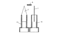
図1(未開封状態)には、符号26で安全セパレータが示されており、この安全セパレータ26は、通路3の縁部と挿入管8の比較的広幅の部分との間で、装置が不本意に開放されないために役立つ。
In FIG. 1 (unopened state), a safety separator is indicated by
刃2,6(図4、図5及び図6参照)は、通路3(図2)を通って導入され、この場合はヨーロッパ特許第787655号明細書とは異なって、明らかにヘッドプレート5の平面4の手前に配置されている。
The
前記の刃2,6の最適な機能を保障するためには、これらの刃を、例えば鋼又はセラミックを以て可能であるように、極めて鋭くシャープに且つ硬質に構成することが不可欠である。
In order to ensure the optimal function of the
但し、この開口管7,8(図4)の他方の側8は、ミキサに対する差込み継手が簡単に被嵌め可能且つ再度引出し可能でもあり、シール作用を有してもいるためには、著しく弾性的且つ柔軟でなければならないので、各管片7,8は少なくとも2つの異なる材料から製作する必要がある。ヨーロッパ特許第1121195号明細書に記載された穿刺管は、硬質の先端部及び弾性的なシール縁部から成る前記の材料コンビネーション並びにこの材料コンビネーションの申し分のない機能を有していない。
However, the
構成部材7,8のための有利な材料は、ポリプロピレン又はポリエチレン等の熱可塑性材料であり、構成部材2,6のための有利な材料は、高い弾性係数を有する特殊鋼、ばね鋼、軽金属、セラミック又は熱可塑性樹脂である。
Advantageous materials for the
極めて靭性の安定したペーストにも使用可能であるためには、フィルムに切り込まれる開口Bができるだけ大きく構成されており、通流通路ができるだけ大きな横断面を備えて構成されており、通流通路の製品に接触する表面が、摩擦減少のためにできるだけ少なく構成されているのが望ましい。 In order to be able to be used for a paste with extremely stable toughness, the opening B cut into the film is configured as large as possible, and the flow passage is configured with a cross section as large as possible. It is desirable that the surface in contact with the product is made as few as possible to reduce friction.
通流通路の長さ及び大きさは、大抵既存のシステムに対する所要の互換性に基づいて規定されているので、要求される特性は、とりわけ開口刃の形状及び座りに基づいて保障される。 Since the length and size of the flow passage are usually defined on the basis of the required compatibility with existing systems, the required properties are guaranteed, inter alia, based on the shape and sitting of the open blade.
つまり、刃は、一方では通流通路壁9の構成部材であり且つ他方ではフィルムに連続した非線形の切込みを生ぜしめるように構成されているので、ペーストの摩擦抵抗は著しく減少され得る。このことは、製品の流れを妨げるように配置された刃(図3)と比較して、決定的な利点を成している。 In other words, the frictional resistance of the paste can be significantly reduced since the blade is on the one hand a component of the flow passage wall 9 and on the other hand is configured to produce a continuous non-linear cut in the film. This is a decisive advantage compared to a blade (FIG. 3) that is arranged to impede product flow.
断面は、L字形、V字形、U字形又は半円形からほぼ円形(図4、B、10)であってよい。 The cross section may be L-shaped, V-shaped, U-shaped or semi-circular to nearly circular (FIGS. 4, B, 10).
このように開封されたバッグの最も小さな押出し力及び製品内のフィルム部分の防止は、バッグの切込みBが3/4円形10の場合に同時に得られる。
The smallest pushing force of the bag opened in this way and the prevention of the film part in the product are obtained simultaneously when the bag cut B is 3/4
これにより、ペースト(粘度約500Pa s)の押出し力は、線形のスリット及び通流通路11(図3)内に配置された刃1による4000〜5000Nから、約2000Nに低下する。 Thereby, the extrusion force of paste (viscosity about 500 Pas) falls from 4000-5000N by the linear slit and the blade 1 arrange | positioned in the flow path 11 (FIG. 3) to about 2000N.
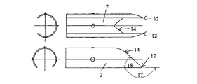
刃形の構成に際して、刃形が、斜めに且つ/又は曲げられて延びる刃のエッジ14によって互いに結合された少なくとも2つの先端部12,13を、フィルムを突き刺すために有していると最適であるということが判った。
In the configuration of the blade shape, it is optimal if the blade shape has at least two
フィルム15(図2)が無制御に引き続き裂断されることを防止するためには、両先端部12の、有利には切断エッジとは反対の側16における切断エッジ14の端部が、切込み方向に対して少なくとも180°の角度17で構成される。先端部12,13として機能するためには、これらの先端部は45°の角度18を超えてはならない。
In order to prevent the film 15 (FIG. 2) from continuing to tear uncontrollably, the ends of the cutting edges 14 of both
刃14の肉厚は、有利には0.5mm未満に保持されている。
The wall thickness of the
バッグの穿刺時又は穿刺後に刃が捩られることを防止したい場合は、捩れ防止が不可欠である。この捩れ防止は、管片7に少なくとも1つ又は複数のウェブ21が取り付けられており、これらのウェブ21が、管片が挿入されるとバッグキャップの通路3内に取り付けられたリングギヤ25に突入して係止する場合に保障される。
When it is desired to prevent the blade from being twisted at the time of puncture of the bag or after the puncture, prevention of twist is essential. In order to prevent the twist, at least one or a plurality of
但し、逆にリングギヤが管片に設けられており且つ単数又は複数のウェブが通路内に配置されていてもよい。 However, conversely, the ring gear may be provided on the pipe piece, and one or a plurality of webs may be disposed in the passage.
捩れが防止されていない場合は、穿刺された状態で管片の回転運動によってバッグフィルムの一部が分離される恐れがある。 If twisting is not prevented, part of the bag film may be separated by the rotational movement of the tube piece in the punctured state.
極端に高い粘稠度(可塑性)を有する製品に関しては、バッグがスリットを付けられて穿刺され且つ穴が広げられるか又はフィルムが打ち抜かれることによって、バッグが流出通路を介して可能な最大直径に開かれることが不可欠であるということが判った。 For products with extremely high consistency (plasticity), the bag is slitted and punctured and the hole is widened or the film is punched out so that the bag is at the maximum diameter possible through the outflow passage. It turns out that opening is essential.
但し、このことがユーザによって別個の工具で実施される場合は、所望の快適性がシステムから失われる。更に、これによってフィルム部分が製品内に一緒に流入する恐れがある。 However, if this is done by the user with a separate tool, the desired comfort is lost from the system. Furthermore, this can cause the film part to flow together into the product.
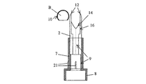
製作過程において、開封機構20と同時に保管期間及び搬送中の栓23として働く構成部材19(図7)を、既に流出通路22に差し込むことが有効であると判った。この場合、エンドユーザは栓23を取り外すだけで済み、このようにして製品は開封されて使用できる状態にある。
In the manufacturing process, it has been found that it is effective to insert the component member 19 (FIG. 7), which functions as the
しかし、バッグの穿刺用部材は鋭くシャープ且つ硬質でなければならないので、バッグが製作過程において穿刺され、次いで、鋭さの無い栓24によって閉じられることによって鋭い栓による怪我の危険が防止されると、ユーザにとって別の利点が得られる。前記の栓24は、ユーザによって引き出され且つ危険無く処理され得る。
However, since the puncture member of the bag must be sharp, sharp and rigid, if the bag is punctured in the manufacturing process and then closed by the
挿入管片7,8及び刃2,6は、有利には異なる材料から成っている。つまり、管片はシール材料から成っており、刃は安定性を有する材料から成っている。
The
シール材料としては、熱可塑性プラスチックが考えられる。刃の材料は、例えば曲げられた鋼、軽金属又はセラミックであってよいが、弾性係数>=3000MPa.を有する熱可塑性プラスチックであってもよい。 As the sealing material, thermoplastics can be considered. The material of the blade may be, for example, bent steel, light metal or ceramic, but the elastic modulus> = 3000 MPa. May be a thermoplastic.
有利な実施例では、バッグが穿刺されると、又は穿刺された状態で、管片7に設けられた1つ又は複数のウェブ21が、通路3に設けられたリングギヤ25と関連して管片の回動を防止する。
In an advantageous embodiment, one or
切り抜かれたフィルム片10は、有利には引き続きバッグ15とつながっており、製品の流れによって流出通路7の壁9に当て付けられる。
The
開封機能は、閉鎖機能と結びつけられていてもよいので、栓19に取り付けられた刃2,6と、シール部材23とを備えた、チューブバッグ15を開封し且つ再封止するための装置が得られる。この場合、有利には栓23及び刃2,6は異なる材料から成っている。即ち、栓はシール材料から成っており、刃は安定性を有する材料から成っている。
Since the opening function may be combined with the closing function, an apparatus for opening and resealing the
従って本発明は、予め開封され且つ再封止されるチューブバッグの製作及び使用にも関する。これらのチューブバッグでは、バッグ15のフィルムの流出通路22の領域が納品前に穿刺され、使用するまで閉鎖栓24によって再度封止される。更に、本発明は、閉鎖栓が挿入される前にフィルム片が打ち抜かれて除去される、前記のように予め開封されたチューブバッグに関する。
The invention therefore also relates to the production and use of a tube bag that has been previously opened and resealed. In these tube bags, the region of the
1,2,6 刃、 3 通路、 5 ヘッドプレート、 7 開口管片、 8 挿入管片、 9 壁、 10 フィルム片、 11 通流通路、 12,13 先端部、 14 切断エッジ、 15 フィルム、 20 開封機構、 21 ウェブ、 22 流出通路、 23,24 栓、 25 リングギヤ、 26 安全セパレータ 1, 2, 6 blades, 3 passages, 5 head plate, 7 open tube piece, 8 insertion tube piece, 9 wall, 10 film piece, 11 flow passage, 12, 13 tip, 14 cutting edge, 15 film, 20 Unsealing mechanism, 21 web, 22 outflow passage, 23, 24 stopper, 25 ring gear, 26 safety separator
Claims (17)
刃(2,6)の形状が、チューブバッグに含まれる材料のための流出開口(11)の内壁(9)に倣っていることを特徴とする、チューブバッグを開封するための装置。 An apparatus for opening a tube bag (15), having an opening (D) facing the tube bag (15) at one end and connected to the opening by a flow passage (0). Further, an insertion tube piece (7, 8) having an outflow opening (11) for the paste-like material contained in the tube bag at the other end, and a blade attached to the insertion tube piece (7, 8) ( 2, 6), and the blade (2, 6) cuts at least one tip (12) facing the tube bag and the tube bag (15) for puncturing the tube bag (15). In the form of having at least one cutting part (14) coupled with the tip for
Device for opening the tube bag, characterized in that the shape of the blade (2, 6) follows the inner wall (9) of the outflow opening (11) for the material contained in the tube bag.
Applications Claiming Priority (1)
| Application Number | Priority Date | Filing Date | Title |
|---|---|---|---|
| DE102004003774A DE102004003774A1 (en) | 2004-01-23 | 2004-01-23 | Device for opening a tubular bag and its use |
Publications (1)
| Publication Number | Publication Date |
|---|---|
| JP2005206254A true JP2005206254A (en) | 2005-08-04 |
Family
ID=34625798
Family Applications (1)
| Application Number | Title | Priority Date | Filing Date |
|---|---|---|---|
| JP2005016181A Withdrawn JP2005206254A (en) | 2004-01-23 | 2005-01-24 | Apparatus for opening tube bag and manufacturing method for tube bag which is opened with apparatus beforehand and re-closed |
Country Status (5)
| Country | Link |
|---|---|
| US (1) | US20050161454A1 (en) |
| EP (1) | EP1557363B1 (en) |
| JP (1) | JP2005206254A (en) |
| AT (1) | ATE385958T1 (en) |
| DE (2) | DE102004003774A1 (en) |
Cited By (1)
| Publication number | Priority date | Publication date | Assignee | Title |
|---|---|---|---|---|
| JP2015531335A (en) * | 2012-10-11 | 2015-11-02 | ヒルティ アクチエンゲゼルシャフト | Sheet material container for dispenser and method for manufacturing sheet material container |
Families Citing this family (6)
| Publication number | Priority date | Publication date | Assignee | Title |
|---|---|---|---|---|
| DE102007018143B3 (en) * | 2007-04-16 | 2008-06-05 | Kettenbach Gmbh & Co. Kg | Container e.g. tubular bag, for receiving e.g. liquid substance, has nozzle and sleeve with lengths adjusted such that sleeve is movable from storage position, in which sleeve does not project, into activation position, by inserting pieces |
| BE1018873A5 (en) * | 2009-08-28 | 2011-10-04 | Cruysberghs Rudiger | DEVICE FOR CONNECTING A FLEXIBLE CONTAINER TO A DIVIDING DEVICE. |
| GB201012094D0 (en) * | 2010-07-19 | 2010-09-01 | 2K Polymer Systems Ltd | Multi-component dispenser |
| PL2520360T3 (en) * | 2011-05-02 | 2014-11-28 | Sulzer Mixpac Ag | Mixer for mixing at least two flowable components, and application device |
| CN105173279A (en) * | 2015-09-02 | 2015-12-23 | 启东江天液压有限公司 | Toothpaste squeezer |
| CN108725919B (en) * | 2018-06-07 | 2020-09-11 | 云南白药集团股份有限公司 | Plaster bag cutting and sheet taking machine and application thereof |
Family Cites Families (21)
| Publication number | Priority date | Publication date | Assignee | Title |
|---|---|---|---|---|
| US2767744A (en) * | 1954-12-27 | 1956-10-23 | Beerman Jack | Liquid transfer device |
| US3595448A (en) * | 1967-08-18 | 1971-07-27 | Ewell Lee Carlton | Sealant dispensers |
| US4267945A (en) * | 1979-08-06 | 1981-05-19 | Maynard Jr Walter P | Liquid funnel and container piercing blade combination |
| US4469249A (en) * | 1980-12-04 | 1984-09-04 | Diemoulders Proprietary Limited | Apparatus for dispensing liquids |
| US4355737A (en) * | 1981-01-16 | 1982-10-26 | Pongrass Robert G | Fluid dispenser |
| US4600125A (en) * | 1983-08-15 | 1986-07-15 | Maynard Jr Walter P | Liquid funnel and pouring spout combination |
| IT1196382B (en) * | 1984-01-03 | 1988-11-16 | Diemoulders Pty Ltd | LIQUID DISPENSER DEVICE |
| DE8405699U1 (en) * | 1984-02-24 | 1984-08-02 | Holle, Helmut, 6832 Hockenheim | VESSEL TO RECEIVE LIQUID PACKS |
| GB8922478D0 (en) * | 1989-10-05 | 1989-11-22 | Procter & Gamble | Flowable product package incorporating a refill facilitating pouring spout |
| DE4316807A1 (en) * | 1993-05-19 | 1994-11-24 | Friedhelm Schneider | Metering gun for tubular bags with highly viscous contents |
| US5405053A (en) * | 1993-08-04 | 1995-04-11 | Uneco Engineering, Inc. | Bulk bag opener and dispenser |
| US6244311B1 (en) * | 1994-12-29 | 2001-06-12 | Bemis Manufacturing Company | Method and apparatus for removing and disposing of body fluids |
| DE59710147D1 (en) * | 1996-02-05 | 2003-07-03 | 3M Espe Ag | Device for emptying a tubular bag |
| JP3187322B2 (en) * | 1996-05-27 | 2001-07-11 | 啓一 中田 | Opening device and sealing material injection container |
| AUPP243598A0 (en) * | 1998-03-18 | 1998-04-09 | Rapak Asia Pacific Limited | Improvements relating to tote bins |
| DE29923938U1 (en) * | 1998-10-14 | 2001-07-19 | Kettenbach Gmbh & Co Kg | Device for discharging a pasty two-component mixture |
| AU4325700A (en) * | 1999-03-26 | 2000-10-16 | Allegiance Corporation | A single-finger activated single-hand operated fluid applicator |
| US6453956B2 (en) * | 1999-11-05 | 2002-09-24 | Medtronic Minimed, Inc. | Needle safe transfer guard |
| US6253804B1 (en) * | 1999-11-05 | 2001-07-03 | Minimed Inc. | Needle safe transfer guard |
| ATE255528T1 (en) * | 2001-01-24 | 2003-12-15 | Heraeus Kulzer Gmbh & Co Kg | DEVICE FOR EMPTYING A HOSE BAG |
| US7073686B2 (en) * | 2003-07-15 | 2006-07-11 | Hanell Edward G | Pouring spout |
-
2004
- 2004-01-23 DE DE102004003774A patent/DE102004003774A1/en not_active Ceased
- 2004-12-27 US US11/023,249 patent/US20050161454A1/en not_active Abandoned
-
2005
- 2005-01-08 AT AT05000295T patent/ATE385958T1/en not_active IP Right Cessation
- 2005-01-08 EP EP05000295A patent/EP1557363B1/en not_active Not-in-force
- 2005-01-08 DE DE502005002783T patent/DE502005002783D1/en not_active Expired - Fee Related
- 2005-01-24 JP JP2005016181A patent/JP2005206254A/en not_active Withdrawn
Cited By (1)
| Publication number | Priority date | Publication date | Assignee | Title |
|---|---|---|---|---|
| JP2015531335A (en) * | 2012-10-11 | 2015-11-02 | ヒルティ アクチエンゲゼルシャフト | Sheet material container for dispenser and method for manufacturing sheet material container |
Also Published As
| Publication number | Publication date |
|---|---|
| EP1557363B1 (en) | 2008-02-13 |
| ATE385958T1 (en) | 2008-03-15 |
| DE502005002783D1 (en) | 2008-03-27 |
| DE102004003774A1 (en) | 2005-08-25 |
| EP1557363A1 (en) | 2005-07-27 |
| US20050161454A1 (en) | 2005-07-28 |
Similar Documents
| Publication | Publication Date | Title |
|---|---|---|
| JP2005206254A (en) | Apparatus for opening tube bag and manufacturing method for tube bag which is opened with apparatus beforehand and re-closed | |
| EP1982922B1 (en) | Container and method for opening a container | |
| EP2692308B1 (en) | Mixing and dispensing container | |
| US10179677B2 (en) | Aseptic package fluid dispensing apparatus and methods of dispensing liquids from flexible packages | |
| US5325995A (en) | Piercing nozzle for pouch fitment | |
| US10287081B2 (en) | Aseptic package fluid dispensing apparatus | |
| US7458486B2 (en) | Self-opening closure for composite packagings or for container or bottle nozzles for sealing with film material | |
| WO2005077769A1 (en) | Flip-top closure for composite and cardboard packaging | |
| JP2545368B2 (en) | Disposable or returnable container for flowable packing | |
| AU2010356074B2 (en) | Tap assembly | |
| US8616090B2 (en) | Bottle seal breaker | |
| WO2005009859A1 (en) | Drinking and pouring closure with a piercing cutter device for composite packagings or container and bottle spouts sealed with a film material | |
| DE102007060382B4 (en) | Slicing device for opening a tubular bag | |
| EP1658225A1 (en) | Pouring spout closure with a piercing cutter for composite packagings or containers sealed with film material | |
| EP1820742A1 (en) | Shutoff device for packages of liquid products | |
| EP1853511B1 (en) | Delivering tap for elastic vessels | |
| US6085941A (en) | Film tube for flowable substances | |
| JPH07330009A (en) | Cap | |
| EP3095728A1 (en) | Device for connecting at least two containers and an assembly comprising the connecting device and attached containers | |
| EP1227049B1 (en) | A tapping device for a tubular bag | |
| CH708269A2 (en) | Paper knife with protected blade and rocker. | |
| EP2737872B1 (en) | Dental container | |
| AU632155B2 (en) | Piercing nozzle for pouch fitment | |
| JP3065670U (en) | Joint filler filling nozzle | |
| US1157489A (en) | Letter-opener. |
Legal Events
| Date | Code | Title | Description |
|---|---|---|---|
| A300 | Application deemed to be withdrawn because no request for examination was validly filed |
Free format text: JAPANESE INTERMEDIATE CODE: A300 Effective date: 20080401 |