JP2005203211A - Electric heating cooker - Google Patents

Electric heating cooker Download PDF

Info

Publication number
JP2005203211A
JP2005203211A JP2004007676A JP2004007676A JP2005203211A JP 2005203211 A JP2005203211 A JP 2005203211A JP 2004007676 A JP2004007676 A JP 2004007676A JP 2004007676 A JP2004007676 A JP 2004007676A JP 2005203211 A JP2005203211 A JP 2005203211A
Authority
JP
Japan
Prior art keywords
heated
temperature
temperature measuring
heating
heating cooker
Prior art date
Legal status (The legal status is an assumption and is not a legal conclusion. Google has not performed a legal analysis and makes no representation as to the accuracy of the status listed.)
Pending
Application number
JP2004007676A
Other languages
Japanese (ja)
Other versions
JP2005203211A5 (en
Inventor
Toshio Koike
利男 小池
Shigeya Matsumoto
茂哉 松本
Current Assignee (The listed assignees may be inaccurate. Google has not performed a legal analysis and makes no representation or warranty as to the accuracy of the list.)
Mitsubishi Electric Home Appliance Co Ltd
Mitsubishi Electric Corp
Original Assignee
Mitsubishi Electric Home Appliance Co Ltd
Mitsubishi Electric Corp
Priority date (The priority date is an assumption and is not a legal conclusion. Google has not performed a legal analysis and makes no representation as to the accuracy of the date listed.)
Filing date
Publication date
Application filed by Mitsubishi Electric Home Appliance Co Ltd, Mitsubishi Electric Corp filed Critical Mitsubishi Electric Home Appliance Co Ltd
Priority to JP2004007676A priority Critical patent/JP2005203211A/en
Priority to CNA2004100348105A priority patent/CN1642366A/en
Priority to KR1020040028922A priority patent/KR100583859B1/en
Publication of JP2005203211A publication Critical patent/JP2005203211A/en
Publication of JP2005203211A5 publication Critical patent/JP2005203211A5/ja
Pending legal-status Critical Current

Links

Images

Classifications

    • BPERFORMING OPERATIONS; TRANSPORTING
    • B42BOOKBINDING; ALBUMS; FILES; SPECIAL PRINTED MATTER
    • B42DBOOKS; BOOK COVERS; LOOSE LEAVES; PRINTED MATTER CHARACTERISED BY IDENTIFICATION OR SECURITY FEATURES; PRINTED MATTER OF SPECIAL FORMAT OR STYLE NOT OTHERWISE PROVIDED FOR; DEVICES FOR USE THEREWITH AND NOT OTHERWISE PROVIDED FOR; MOVABLE-STRIP WRITING OR READING APPARATUS
    • B42D1/00Books or other bound products
    • BPERFORMING OPERATIONS; TRANSPORTING
    • B42BOOKBINDING; ALBUMS; FILES; SPECIAL PRINTED MATTER
    • B42DBOOKS; BOOK COVERS; LOOSE LEAVES; PRINTED MATTER CHARACTERISED BY IDENTIFICATION OR SECURITY FEATURES; PRINTED MATTER OF SPECIAL FORMAT OR STYLE NOT OTHERWISE PROVIDED FOR; DEVICES FOR USE THEREWITH AND NOT OTHERWISE PROVIDED FOR; MOVABLE-STRIP WRITING OR READING APPARATUS
    • B42D3/00Book covers
    • BPERFORMING OPERATIONS; TRANSPORTING
    • B42BOOKBINDING; ALBUMS; FILES; SPECIAL PRINTED MATTER
    • B42FSHEETS TEMPORARILY ATTACHED TOGETHER; FILING APPLIANCES; FILE CARDS; INDEXING
    • B42F13/00Filing appliances with means for engaging perforations or slots
    • B42F13/02Filing appliances with means for engaging perforations or slots with flexible or resilient means
    • B42F13/04Filing appliances with means for engaging perforations or slots with flexible or resilient means with cords, coils, or chains

Abstract

<P>PROBLEM TO BE SOLVED: To provide an electric heating cooker which prevents the abnormal heating or the like of an object to be heated, and whose safety is enhanced. <P>SOLUTION: The electric heating cooker 1 is provided with a top plate 5 on which the object to be heated 36 is put, a body case 2 where the top plate 5 is attached to its top surface, a heating unit 20 for performing heating by an induction coil 22, an electric resistor or the like provided in the body case 2, a controller 34 for controlling the output of the heating unit 20 or the like, a blower 35 for cooling heat generating components provided in the body case 2, and a temperature detector 27 for measuring the temperature of the object 36. The controller 34 stops or lowers an output to the heating unit 20 when a temperature rise width per predetermined time interval of the object 36 detected by the temperature detector 27 is not larger than a predetermined value, after heating is started by the heating unit 20. <P>COPYRIGHT: (C)2005,JPO&NCIPI

Description

本発明は、電気加熱調理器、特に電気加熱調理器の安全性向上の改良に関するものである。   The present invention relates to an improvement in safety of an electric heating cooker, particularly an electric heating cooker.

従来、誘導コイルや電気抵抗体等の加熱体により天板上面に載置された被加熱物の加熱調理を行うものとして、天板左側に左加熱部、右側に右加熱部、後部中央に中央加熱部の3箇所の加熱部を有している電気加熱調理器が知られている。このような従来における電気加熱調理器は被加熱物である調理鍋等の調理器の温度を天板下面に設けた温度センサで検知することにより、調理の進行度合いを検知して加熱制御を行い、自動調理等を行っていた。   Conventionally, a heating object placed on the top plate is heated by a heating body such as an induction coil or an electric resistor. The left heating unit is on the left side of the top plate, the right heating unit is on the right side, and the center is on the rear center. An electric heating cooker having three heating parts of a heating part is known. In such a conventional electric heating cooker, the temperature of the cooking device such as a cooking pan as a heated object is detected by a temperature sensor provided on the lower surface of the top plate, thereby detecting the degree of cooking and performing heating control. , Automatic cooking and so on.

このような電気加熱調理器の温度センサとして、応答性が非常に良好な赤外線センサによる放射温度方式を応用したものが提案されている。該電気加熱調理器は、箱状の本体ケースの天面開口を覆う天板上面に被加熱物を載置し、天板の下方にLEDやレーザなどの発光素子や受光素子及び赤外線センサを設け、発光素子から被加熱物に投光し、被加熱物から反射した反射光を受光素子で受光し、その受光した出力から換算した被加熱物の放射率、及び赤外線センサの受光量から被加熱物の温度を換算することにより、被加熱物の正確な温度を検知するように構成されていた(特許文献1参照)。   As a temperature sensor of such an electric heating cooker, an application of a radiation temperature method using an infrared sensor with very good response has been proposed. The electric heating cooker places an object to be heated on the top surface of the top plate that covers the top surface opening of the box-shaped main body case, and is provided with a light emitting element such as an LED or a laser, a light receiving element, and an infrared sensor below the top panel. The light is projected from the light emitting element onto the object to be heated, and the reflected light reflected from the object to be heated is received by the light receiving element, and the object is heated from the emissivity of the object to be heated converted from the received output and the amount of light received by the infrared sensor. It was comprised so that the exact temperature of a to-be-heated object might be detected by converting the temperature of an object (refer patent document 1).

特開平11−225881号公報Japanese Patent Laid-Open No. 11-225881

前述のような構成により、電気加熱調理器は被加熱物の温度を検知していた。そして、その検知された温度に基づいて加熱出力を調整するように構成されているのが一般的であったが、例えば使用者が調理中に被加熱物の温度検知を行いづらいような位置に調理鍋などを載置してしまった場合や、天板などの温度検知面が汚れてしまった場合などでは、電気加熱調理器の温度検知精度が向上されても被加熱物の温度が正確に計測できず、被加熱物は加熱され続けているにも関わらず、実際より低温で検知されてしまうため、さらに高出力で加熱しようとするようなことや、温度を検知するセンサが故障してしまっていた場合などは、実際の被加熱物は既に目標とする加熱温度に達しているにもかかわらず、電気加熱調理器では被加熱物の温度が検知されないため、やはり高出力で加熱しようとするようなこともあり、このような場合では異常過加熱となり危険であるという問題があった。   With the configuration as described above, the electric heating cooker has detected the temperature of the object to be heated. In general, the heating output is adjusted based on the detected temperature. For example, it is difficult for the user to detect the temperature of the object to be heated during cooking. If a cooking pan is placed or the temperature detection surface of the top plate is dirty, the temperature of the object to be heated will be accurate even if the temperature detection accuracy of the electric heating cooker is improved. Although the object to be heated cannot be measured and the object to be heated continues to be heated, it is detected at a lower temperature than the actual temperature. In the case where the target object has already reached the target heating temperature, the electric heating cooker does not detect the temperature of the object to be heated. Sometimes In case that there is a problem that it is dangerous indicates abnormal overheating.

本発明は、前記課題に鑑み為されたものであり、被加熱物の異常加熱などを防止し得る安全性を向上した電気加熱調理器を提供することを目的とする。   This invention is made | formed in view of the said subject, and it aims at providing the electric heating cooking appliance which improved the safety | security which can prevent the abnormal heating etc. of a to-be-heated material.

前記目的を達成するために、本発明にかかる電気加熱調理器は、被加熱物を載置する天板と、前記天板が天面に取り付けられた本体ケースと、前記本体ケース内部に設けられた誘導コイルや電気抵抗体等により加熱する加熱体と、前記加熱体の出力などを制御する制御体と、前記本体ケース内部に備えられた発熱部品を冷却する送風機と、前記被加熱物の温度を測定する測温体とを備え、前記制御体は、前記加熱体により加熱が開始された後、前記測温体で検出した前記被加熱物の所定時間当たりにおける温度上昇幅が所定の値以下のときは、前記加熱体への出力の停止若しくは出力の低下を行うことを特徴とする。   In order to achieve the above object, an electric heating cooker according to the present invention is provided with a top plate on which an object to be heated is placed, a main body case on which the top plate is attached to the top surface, and the main body case. A heating body that is heated by an induction coil, an electric resistor, etc., a control body that controls the output of the heating body, a blower that cools a heat generating component provided in the body case, and a temperature of the object to be heated A temperature measuring body for measuring the temperature of the object to be heated per predetermined time detected by the temperature measuring body after heating by the heating body is less than a predetermined value. In this case, the output to the heating body is stopped or the output is reduced.

また、本発明にかかる電気加熱調理器は、被加熱物を載置する天板と、前記天板が天面に取り付けられた本体ケースと、前記本体ケース内部に設けられた誘導コイルや電気抵抗体等により加熱する加熱体と、前記加熱体の出力などを制御する制御体と、前記本体ケース内部に備えられた発熱部品を冷却する送風機と、前記被加熱物の温度を測定する測温体と、前記本体ケースに設けられ表示若しくは警告音などを告知する告知手段とを備え、前記制御体は、前記加熱体により加熱が開始された後、前記測温体で検出した前記被加熱物の所定時間当たりにおける温度上昇幅が所定の値以下のときは、前記告知手段により前記表示若しくは警告音などで告知することを特徴とする。   An electric heating cooker according to the present invention includes a top plate on which an object to be heated is placed, a main body case on which the top plate is attached to the top surface, an induction coil and an electric resistance provided inside the main body case. A heating body that is heated by a body, a control body that controls an output of the heating body, a blower that cools a heat generating component provided in the body case, and a temperature measuring body that measures the temperature of the object to be heated And a notification means that is provided in the main body case and notifies a display or warning sound, etc., and the control body of the object to be heated detected by the temperature measuring body after the heating body starts heating. When the temperature rise width per predetermined time is below a predetermined value, the notification means notifies the user with the display or warning sound.

本発明の電気加熱調理器は、被加熱物を載置する天板と、天板が天面に取り付けられた本体ケースと、本体ケース内部に設けられた誘導コイルや電気抵抗体等により加熱する加熱体と、加熱体の出力などを制御する制御体と、本体ケース内部に備えられた発熱部品を冷却する送風機と、被加熱物の温度を測定する測温体とを備えている。そして、制御体は、加熱体により加熱が開始された後、測温体で検出した被加熱物の所定時間当たりにおける温度上昇幅が所定の値以下のときは、加熱体への出力の停止若しくは出力の低下を行うので、例えば被加熱物の温度が正確に検知できない場合などに、被加熱物の温度が異常に上昇してしまう危険性を未然に防止することができる。これにより、電気加熱調理器の安全性を極めて向上することができるようになるものである。   The electric heating cooker of the present invention heats a top plate on which an object to be heated is placed, a main body case with the top plate attached to the top surface, an induction coil or an electric resistor provided inside the main body case, and the like. A heating body, a control body that controls the output of the heating body, a blower that cools a heat generating component provided inside the main body case, and a temperature measuring body that measures the temperature of the object to be heated are provided. Then, after the heating body starts heating, the control body stops the output to the heating body when the temperature rise width per predetermined time of the object to be heated detected by the temperature measuring body is equal to or less than a predetermined value or Since the output is reduced, for example, when the temperature of the object to be heated cannot be accurately detected, it is possible to prevent the danger that the temperature of the object to be heated will rise abnormally. Thereby, the safety | security of an electric heating cooking appliance can be improved very much.

また、本発明の電気加熱調理器は、被加熱物を載置する天板と、天板が天面に取り付けられた本体ケースと、本体ケース内部に設けられた誘導コイルや電気抵抗体等により加熱する加熱体と、加熱体の出力などを制御する制御体と、本体ケース内部に備えられた発熱部品を冷却する送風機と、被加熱物の温度を測定する測温体と、本体ケースに設けられ表示若しくは警告音などを告知する告知手段とを備え、制御体は、加熱体により加熱が開始された後、測温体で検出した被加熱物の所定時間当たりにおける温度上昇幅が所定の値以下のときは、告知手段により表示若しくは警告音などで告知するので、例えば被加熱物の温度が正確に検知できない場合などに、被加熱物の温度が異常に上昇してしまう危険性を使用者に迅速に知らせることができ、電気加熱調理器の安全性を極めて向上することができるようになるものである。   Moreover, the electric heating cooker of the present invention includes a top plate on which an object to be heated is placed, a main body case on which the top plate is attached to the top surface, an induction coil and an electric resistor provided inside the main body case, and the like. A heating body to be heated, a control body for controlling the output of the heating body, a blower for cooling the heat generating components provided in the body case, a temperature measuring body for measuring the temperature of the object to be heated, and a body case And a control means for notifying the display or warning sound, etc., and after the heating body starts heating, the control body has a predetermined temperature rise width per predetermined time detected by the temperature measuring body. In the following cases, the notification means notifies the user with a display or a warning sound. For example, when the temperature of the heated object cannot be accurately detected, the user may be at a risk of the temperature of the heated object rising abnormally. To be informed quickly Can, is made of the safety of the electrical heating cooker so very it can be improved.

実施の形態1.
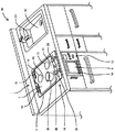
以下、本発明の一実施形態に基づき、本発明を詳しく説明する。図1は本実施形態における電気加熱調理器1を備えた流し台90の斜視図、図2は本実施形態における電気加熱調理器1の斜視図をそれぞれ示している。図1において、流し台90にはシンク92が設けられており、このシンク92奥の上部には図示しない水道管の先に取り付けられた蛇口94が設けられると共に、シンク92横には図示しない包丁で野菜や肉などの被調理物を適当な大きさに切り刻むための受け台としてのまな板(図示せず)等が載置できるように構成されている。
Embodiment 1 FIG.
Hereinafter, the present invention will be described in detail based on an embodiment of the present invention. FIG. 1 is a perspective view of a sink 90 provided with the electric heating cooker 1 in the present embodiment, and FIG. 2 is a perspective view of the electric heating cooker 1 in the present embodiment. In FIG. 1, a sink 92 is provided in the sink 90, and a faucet 94 attached to the tip of a water pipe (not shown) is provided in the upper part of the sink 92, and a knife (not shown) is provided beside the sink 92. A cutting board (not shown) serving as a cradle for chopping an object to be cooked such as vegetables or meat into an appropriate size can be placed.

シンク92横には所定の間隔を存して電気加熱調理器1が流し台90に組み込まれており、この電気加熱調理器1は、天面が開口された箱状の本体ケース2(図2に図示)と、この本体ケース2の天面開口部を覆う天板5と、この天板5の外周に設けられた金属板からなる枠体6とを有している。該天板5は例えばセラミックスプレート或いは耐熱ガラスなどの如き非磁性材料にて構成され、枠体6の上面開口に接着剤等により固定されている。   Next to the sink 92, the electric heating cooker 1 is incorporated in the sink 90 at a predetermined interval. The electric heating cooker 1 has a box-shaped main body case 2 (see FIG. 2) whose top surface is opened. And a top plate 5 covering the top opening of the main body case 2 and a frame 6 made of a metal plate provided on the outer periphery of the top plate 5. The top plate 5 is made of a nonmagnetic material such as a ceramic plate or heat-resistant glass, and is fixed to the upper surface opening of the frame 6 with an adhesive or the like.

そして、天板5の上面には磁性材料からなる調理鍋やフライパンなどの被加熱物36(図1では調理鍋を図示している)等の載置位置を表示する載置部として後部中央にサークルライン7A、前部左側にサークルライン7B(図2に図示)、前部右側にサークルライン7Cがそれぞれ設けられている。各サークルライン7A、7B、7Cの直径は後述する加熱体20の外径と略等しいか、又は若干大きく形成されると共に、各サークルライン7A、7B、7C近傍には当該各サークルライン7A、7B、7Cに合わせて載置された被加熱物36を加熱する火力の表示を行う出力表示部8A、8B、8Cがそれぞれ設けられている。   And on the upper surface of the top plate 5, as a mounting portion for displaying the mounting position of a heated object 36 such as a cooking pan or a frying pan made of a magnetic material (the cooking pan is shown in FIG. 1), a central portion in the rear part is displayed. A circle line 7A, a circle line 7B (shown in FIG. 2) on the front left side, and a circle line 7C on the front right side are provided. The diameter of each circle line 7A, 7B, 7C is substantially equal to or slightly larger than the outer diameter of the heating body 20 described later, and each circle line 7A, 7B is located near each circle line 7A, 7B, 7C. , 7C, output display units 8A, 8B, and 8C for displaying the heating power for heating the object to be heated 36 placed in accordance with 7C are provided.

本体ケース2の前面上部には、図2に示すように本体ケース2内部に外気を取り込むための吸気口18が設けられると共に、本体ケース2の後部(枠体6の後部両側)には本体ケース2内部に取り込んだ空気を排出するための排気口19が設けられている。吸気口18は、本体ケース2の一部を構成しながら吸気口18から本体ケース2内部に異物の侵入を防止するための吸気フィルタを備えている。   As shown in FIG. 2, an air inlet 18 for taking outside air into the main body case 2 is provided at the upper front of the main body case 2, and the main body case is provided at the rear part of the main body case 2 (on both sides of the rear part of the frame body 6) 2 is provided with an exhaust port 19 for exhausting air taken into the interior. The intake port 18 includes an intake filter for preventing foreign matter from entering the main body case 2 from the intake port 18 while constituting a part of the main body case 2.

また、本体ケース2の前面左側には、グリラー9が設けられており、このグリラー9の前面には本体ケース2内にグリラー9を出し入れするための取っ手9Aが設けられている。本体ケース2の前面右側(グリラー9の右側)には各サークルライン7A、7B、7Cに対応して本体ケース2内に設けられた各加熱体20の加熱出力の調整を行うための出没自在なツマミ10(出没しないツマミでも差し支えない)やグリラー9の加熱出力の調整、及び電気加熱調理器1の電源スイッチのON/OFFや、調理時間を設定したり、計測したりするためのタイマー等を有した操作パネル11を備えた操作部12が設けられている。また、前記枠体6の前部側には図示しないが操作部12に連動して加熱体20の加熱出力の調整を行う複数の操作ボタンや、設定温度、設定時間などを表示するための表示部を備えた天板操作部16が設けられている。   Further, a griller 9 is provided on the left side of the front surface of the main body case 2, and a handle 9 </ b> A is provided on the front surface of the griller 9 for taking the gliller 9 in and out of the main body case 2. The front right side of the main body case 2 (the right side of the griller 9) can be freely moved to adjust the heating output of each heating body 20 provided in the main body case 2 corresponding to each circle line 7A, 7B, 7C. Adjusting the heating output of knob 10 (a knob that does not appear or disappear) and the heating output of the griller 9, turning on / off the power switch of the electric heating cooker 1, a timer for setting and measuring the cooking time, etc. An operation unit 12 including the operation panel 11 is provided. In addition, although not shown in the drawing, a plurality of operation buttons for adjusting the heating output of the heating body 20 in conjunction with the operation unit 12 and a display for displaying a set temperature, a set time, etc. A top panel operating unit 16 having a unit is provided.

サークルライン7A、7B、7Cの下側には、図3に示すように、本体ケース2内部となる天板5の下面側にコイル台22A上に渦巻状に巻かれた誘導コイル22や電気抵抗体(図示せず)等により加熱する加熱体20が設けられている。なお図3ではサークルライン7Bの断面図を示しており、誘導コイル22の中心部には天板5の下面に当接してサークルライン7B上に載置された被加熱物36の底面温度を測定する温度センサ23が設けられている。   Below the circle lines 7A, 7B, and 7C, as shown in FIG. 3, the induction coil 22 spirally wound on the coil base 22A on the lower surface side of the top plate 5 inside the main body case 2 and the electric resistance A heating body 20 that is heated by a body (not shown) or the like is provided. 3 shows a cross-sectional view of the circle line 7B, and measures the bottom surface temperature of the object to be heated 36 placed on the circle line 7B in contact with the lower surface of the top plate 5 at the center of the induction coil 22. A temperature sensor 23 is provided.

本体ケース2内部には電源部や様々な電子素子やマイコン等を含む加熱体20の出力制御回路や予約タイマー制御回路等を備えた制御体34が設けられている。制御体34には加熱体20及び温度センサ23等が接続されると共に、制御体34は加熱体20の加熱の停止、或いは、加熱体20の出力の低下を含む、加熱出力の制御を行うように構成されている。尚、本実施形態における電気加熱調理器1は、サークルライン7Cに対応して図3に示したように天板5の下面側に誘導コイル22同様の誘導コイル及び温度センサが設けられた同様の構造を有している。また、サークルライン7Aに対応した部分には、図3に示した誘導コイル22の代わりに、天板5の下面側に電気抵抗体からなる加熱体が設けられている。その他は図3と同様の構造を有し、温度センサなどが設けられている。   Inside the main body case 2 is provided a control body 34 provided with an output control circuit for the heating body 20 including a power supply unit, various electronic elements, a microcomputer, a reservation timer control circuit, and the like. The control body 34 is connected to the heating body 20, the temperature sensor 23, and the like, and the control body 34 controls the heating output including stopping the heating of the heating body 20 or reducing the output of the heating body 20. It is configured. In addition, the electric heating cooker 1 in this embodiment is the same in which an induction coil and a temperature sensor similar to the induction coil 22 are provided on the lower surface side of the top plate 5 as shown in FIG. 3 corresponding to the circle line 7C. It has a structure. Further, in the portion corresponding to the circle line 7A, a heating body made of an electric resistor is provided on the lower surface side of the top plate 5 instead of the induction coil 22 shown in FIG. Others have the same structure as in FIG. 3, and a temperature sensor or the like is provided.

また、加熱体20及び制御体34は電気加熱調理器1の動作によって熱を持つため、放熱フィン(図示せず)が設けられると共に、加熱された本体ケース2内部を冷却するためモータMにて駆動される送風機35を本体ケース2内に備えている。そして、モータMが駆動して送風機35が運転されると吸気口18から本体ケース2内部に導入された外気(図3白抜き矢印)は、加熱体20或いは制御体34等の加熱部品、及び、天板5や他の加熱された部品を空冷(図3矢印)した後、本体後部に設けた排気口19より本体外部に排出される。   Moreover, since the heating body 20 and the control body 34 have heat by operation | movement of the electric heating cooking appliance 1, while being provided with a radiation fin (not shown), in order to cool the heated main body case 2 inside with the motor M A blower 35 to be driven is provided in the main body case 2. When the motor M is driven and the blower 35 is operated, the outside air introduced into the main body case 2 from the intake port 18 (the white arrow in FIG. 3) is heated by the heating body 20 or the control body 34, and the like. After the top plate 5 and other heated parts are air-cooled (arrows in FIG. 3), they are discharged from the exhaust port 19 provided at the rear of the main body to the outside of the main body.

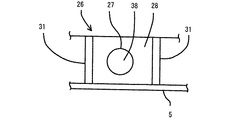
一方、本実施形態における電気加熱調理器1は、本体ケース2の天面となる枠体6に被加熱物36の温度測定をする測温体27を備えている。この測温体27は、赤外線センサにて構成されると共に、測温体27は枠体6の手前側上面部を突出させた2箇所の突出部26内にそれぞれ設けられている。測温体27は温度検知部38を有しており、この温度検知部38にて被加熱物36から発生する赤外線を検知することにより被加熱物36に触れずに温度を測定することができるように構成されている。即ち、測温体27は枠体6の手前側に位置する天板操作部16を所定寸法突出させた突出部26内に設けられると共に、突出部26は、被加熱物36が載置される前部左側のサークルライン7B及び前部右側のサークルライン7Cに最も近接する天板操作部16にそれぞれ設けられている。   On the other hand, the electric heating cooker 1 in the present embodiment includes a temperature measuring body 27 that measures the temperature of the object to be heated 36 on the frame 6 that is the top surface of the main body case 2. The temperature measuring body 27 is composed of an infrared sensor, and the temperature measuring body 27 is provided in two projecting portions 26 that project the front upper surface portion of the frame 6. The temperature measuring element 27 has a temperature detection unit 38, and the temperature detection unit 38 can measure the temperature without touching the object to be heated 36 by detecting infrared rays generated from the object to be heated 36. It is configured as follows. That is, the temperature measuring body 27 is provided in a protruding portion 26 in which the top panel operating portion 16 located on the front side of the frame body 6 is protruded by a predetermined dimension, and the object to be heated 36 is placed on the protruding portion 26. They are respectively provided on the top panel operation unit 16 closest to the circle line 7B on the left side of the front part and the circle line 7C on the right side of the front part.

両突出部26は、サークルライン7B、7C側から離間するに従って天板操作部16より所定寸法突出した傾斜面28を形成すると共に、傾斜面28の上端から更に離間するに従って天板操作部16と平面位置まで緩やかに傾斜する反対側傾斜面30を備えた山形に突出形成されている。この傾斜面28は、サークルライン7B、7C上に載置された被加熱物36の全高の中央より下方側に指向させると共に、被加熱物36の下端より所定寸法上方に指向させている。詳しくは、被加熱物36の高さを10分割したとすると、傾斜面28は一般的な鍋などの被加熱物36の高さにおける下部から上部方向へ2〜5分割の間に指向させている。   Both protrusions 26 form an inclined surface 28 that protrudes by a predetermined dimension from the top panel operation unit 16 as the distance from the circle lines 7B and 7C increases, and further from the top panel operation unit 16 as the distance from the upper end of the inclined surface 28 increases. It is formed so as to project into a mountain shape with an opposite inclined surface 30 that gently inclines to a planar position. The inclined surface 28 is directed downward from the center of the overall height of the object to be heated 36 placed on the circle lines 7B and 7C, and is directed upward by a predetermined dimension from the lower end of the object to be heated 36. Specifically, assuming that the height of the object to be heated 36 is divided into 10 parts, the inclined surface 28 is oriented between 2 to 5 parts from the lower part to the upper part at the height of the object to be heated 36 such as a general pan. Yes.

傾斜面28には図4に示すように貫通孔28Aが設けられており、この貫通孔28A周囲には突出部26内側に延在して測温体27を保持するための保持部29が設けられている。測温体27は、突出部26の内側から保持部29内に挿入されると共に、傾斜面28に略面一まで挿入されている。該測温体27は、貫通孔28Aから被加熱物36方向に露出させると共に傾斜面28と同じ被加熱物36の高さを10分割したとすると、一般的な鍋などの被加熱物36の高さにおける下部から上部方向へ2〜5分割の間に指向させた状態で、突出部26の内側から接着剤(図示せず)にて接着固定されている。即ち、測温体27の温度検知部38を傾斜面28の貫通孔28Aから露出させることにより、被加熱物36から発生する赤外線を直接検知できるようになっている。即ち、突出部26は使用者と反対側となる天板5の被加熱物36載置側に傾斜面28を有すると共に、測温体27は傾斜面28に配置されて被加熱物36の温度を測定できるように配置されている。   As shown in FIG. 4, the inclined surface 28 is provided with a through hole 28 </ b> A, and a holding portion 29 is provided around the through hole 28 </ b> A so as to extend inside the protruding portion 26 and hold the temperature measuring body 27. It has been. The temperature measuring body 27 is inserted into the holding portion 29 from the inside of the protruding portion 26, and is inserted to the inclined surface 28 to be substantially flush. When the temperature measuring body 27 is exposed in the direction of the object to be heated 36 from the through hole 28A and the height of the object to be heated 36 that is the same as the inclined surface 28 is divided into ten parts, the object to be heated 36 such as a general pan is heated. It is bonded and fixed with an adhesive (not shown) from the inside of the protrusion 26 in a state where it is oriented between 2 to 5 divisions from the lower part to the upper part at the height. That is, by exposing the temperature detector 38 of the temperature measuring body 27 from the through hole 28 </ b> A of the inclined surface 28, infrared rays generated from the heated object 36 can be directly detected. That is, the protrusion 26 has an inclined surface 28 on the side of the top plate 5 on the side opposite to the user on which the object to be heated 36 is placed, and the temperature measuring body 27 is disposed on the inclined surface 28 so that the temperature of the object to be heated 36 is increased. It is arranged so that can be measured.

本実施形態における電気加熱調理器1では、測温体27を被加熱物36に近接して天板5外周の枠体6に形成すると共に、電気加熱調理器1天面の前後方向の中央より前側に設けているので、例えば天板5外周の枠体6後部に測温体27を設けた場合には温度検知部38と被加熱物36間に他の調理鍋や皿等が置かれて被加熱物36の温度が測定不可能となってしまうなどの不都合も考えられるが、これを回避することができる。これにより、被加熱物36の温度測定の確実性を向上することができる。特に、天板5外周の枠体6後部に測温体27を設けた場合と異なり、測温体27の温度検知部38が使用者側を向いていないので、天板5上に被加熱物36を載置していない場合に使用者の温度を測定してしまうなどの不都合も防止することができる。   In the electric heating cooker 1 in the present embodiment, the temperature measuring body 27 is formed on the frame 6 on the outer periphery of the top plate 5 in the vicinity of the object to be heated 36, and from the center in the front-rear direction of the top surface of the electric heating cooker 1. Since it is provided on the front side, for example, when the temperature measuring body 27 is provided at the rear part of the frame body 6 on the outer periphery of the top plate 5, other cooking pots or dishes are placed between the temperature detection unit 38 and the heated object 36. There may be inconveniences such as the temperature of the object to be heated 36 being impossible to measure, but this can be avoided. Thereby, the certainty of the temperature measurement of the to-be-heated material 36 can be improved. In particular, unlike the case where the temperature measuring body 27 is provided at the rear part of the frame 6 on the outer periphery of the top plate 5, the temperature detection unit 38 of the temperature measuring body 27 does not face the user side. Inconveniences such as measuring the temperature of the user when 36 is not placed can also be prevented.

他方、図3に示すように、突出部26の傾斜面28と反対側に形成した傾斜面30には告知手段32を設けている。該告知手段32は、各サークルライン7B、7Cの前部に対応してそれぞれ設けると共に、電気加熱調理器1に異常が発生した際などに、文字や絵などで告知する表示手段と、告知音を発生させる音発生手段にて構成されている。表示手段は、文字や絵などを表示可能な複数の7セグメントLEDや液晶表示器などにて構成されると共に、音発生手段は音声や一定音或いはホイッスル音などを発生させるブザーやスピーカなどにて構成されている。この告知手段32としての複数の7セグメントのLEDや液晶表示器などには測温体27(温度検知部38)により検知された被加熱物36の温度が表示される。   On the other hand, as shown in FIG. 3, notification means 32 is provided on the inclined surface 30 formed on the opposite side of the inclined surface 28 of the protruding portion 26. The notification means 32 is provided corresponding to the front part of each of the circle lines 7B and 7C, and when there is an abnormality in the electric heating cooker 1, for example, a display means for notifying with letters or pictures, a notification sound It is comprised with the sound generation means to generate | occur | produce. The display means is composed of a plurality of 7-segment LEDs and liquid crystal displays that can display characters, pictures, etc., and the sound generating means is a buzzer or speaker that generates sound, a constant sound or a whistle sound, etc. It is configured. The temperature of the object to be heated 36 detected by the temperature measuring element 27 (temperature detection unit 38) is displayed on a plurality of 7-segment LEDs, a liquid crystal display, or the like as the notification means 32.

告知手段32は、制御体34に接続されており被加熱物36の異常温度上昇或いは測温体27の温度検知部38により十分な温度上昇が検知できない場合、その異常内容を文字や絵で告知すると同時に音声や音で告知する。例えば異常温度上昇を告知する場合には「異常高温です。」などと告知したり、温度上昇が十分に検知できない場合には、「正しい温度が検知できません。加熱物が正しい位置に置かれているか、検知部表面に汚れがないか、加熱物と検知部の間に障害物がないか確認してください。」などと告知する。これにより、使用者は電気加熱調理器1の異常内容を迅速に把握できる。また、各被加熱物36に対応して枠体6前部に突出部26を設けているので、どの被加熱物36に異常が発生しているかを一目瞭然に把握することができると共に、表示手段を視認しなくても音発生手段からの音声告知で異常を把握することができるので、より迅速に電気加熱調理器1の異常を把握することができる。   The notification means 32 is connected to the control body 34, and when the abnormal temperature rise of the object to be heated 36 or the temperature detection unit 38 of the temperature measuring body 27 cannot be detected sufficiently, the notification means 32 notifies the content of the abnormality with characters or pictures. At the same time, it announces by voice and sound. For example, when an abnormal temperature rise is announced, “abnormally high temperature” is reported, or when the temperature rise cannot be detected sufficiently, “The correct temperature cannot be detected. Is the heated object placed in the correct position? Make sure that the surface of the detector is clean and that there are no obstructions between the heated object and the detector. " Thereby, the user can grasp | ascertain rapidly the abnormal content of the electric heating cooking appliance 1. FIG. In addition, since the protrusion 26 is provided at the front of the frame 6 corresponding to each object to be heated 36, it is possible to grasp at a glance which object to be heated 36 is abnormal and display means. Since the abnormality can be grasped by the sound notification from the sound generating means without visually recognizing, the abnormality of the electric heating cooker 1 can be grasped more quickly.

即ち、天板5上面に突出して測温体27を設けているので、従来のように天板下側から、天板を介して上面の被加熱物36を測定する場合に比較して、被加熱物36の外表面を直接測定することが可能となる。これにより、被加熱物36の温度をより正確に測定することができる。また、測温体27の温度検知部38の外表面の汚れ等の異常を表示乃至音で知らせるので測温体27の温度検知部38の外表面が煮こぼれによる水分で覆われてしまうなどの不都合を防止することができ、被加熱物36の温度を更に正確に測定することができる。   In other words, since the temperature measuring element 27 is provided so as to protrude from the top surface of the top plate 5, compared with the conventional case where the heated object 36 on the top surface is measured from the bottom side of the top plate through the top plate. It becomes possible to directly measure the outer surface of the heated object 36. Thereby, the temperature of the article to be heated 36 can be measured more accurately. In addition, since abnormalities such as dirt on the outer surface of the temperature detection unit 38 of the temperature measuring body 27 are notified by display or sound, the outer surface of the temperature detection unit 38 of the temperature measurement body 27 is covered with moisture due to boiling. Inconvenience can be prevented, and the temperature of the object to be heated 36 can be measured more accurately.

このように、被加熱物36に対応して突出部26内に測温体27を設けると共に、測温体27近傍に告知手段32を設けているので、告知手段32を見るだけで測温体27がどの被加熱物36の温度を測定し表示しているのか分かり、どの被加熱物36の温度であるか間違うことがなく便利である。また、測温体27近傍に告知手段32を設けているので清掃個所が分かりやすく便利である。これにより、測温体27の温度検知部38の表面が煮物汁や水滴や埃などで汚れ、告知手段32がその異常を報知した場合に、告知手段32近傍の測温体27の温度検知部38を清掃するだけで簡単に異常を回避することができる。尚、本実施形態では告知手段32として表示手段と音発生手段を設けたが、告知手段32は表示手段と音発生手段とのどちらか一方だけでも差し支えない。この場合、どちらか一方で異常を告知できるので、部品点数を少なくできコストの低減を行うことができる。   As described above, the temperature measuring body 27 is provided in the projecting portion 26 corresponding to the object to be heated 36, and the notification means 32 is provided in the vicinity of the temperature measurement body 27. It is convenient that the temperature of the object to be heated 36 is measured and displayed on the display 27 and the temperature of the object to be heated 36 is not mistaken. Moreover, since the notification means 32 is provided in the vicinity of the temperature measuring body 27, the cleaning location is easy to understand and convenient. Thereby, when the surface of the temperature detection part 38 of the temperature measuring body 27 is soiled with boiled juice, water droplets, dust, etc., and the notification means 32 notifies the abnormality, the temperature detection part of the temperature measurement body 27 in the vicinity of the notification means 32 Abnormalities can be easily avoided simply by cleaning 38. In this embodiment, the display means and the sound generation means are provided as the notification means 32. However, the notification means 32 may be either the display means or the sound generation means. In this case, since either one can be notified of an abnormality, the number of parts can be reduced and the cost can be reduced.

また、突出部26の傾斜面28に測温体27が固定された状態で、測温体27を一般的な鍋などの被加熱物36の高さの中央より下方側に指向させると共に、被加熱物36の下部より所定寸法上方に指向させているので、測温体27は被加熱物36の下部より所定寸法上方の温度(図3点線矢印)を直接検知することができる。即ち、測温体27は被加熱物36の高さの中央より下方側で被加熱物36の下部より所定寸法上方の温度を測定可能にしているので、測温体27の温度検知部38と被加熱物36間に箸やスプーンなどの小さな障害物が置かれた場合などでも、測温体27はそれら障害物の上側から被加熱物36の温度を測定することができる。これにより、測温体27の温度検知部38と被加熱物36間が遮断されることが防止され、被加熱物36の温度を良好に測定することができる。なお、被加熱物36として高さの低いフライパンや、高さの異なる鍋などの、より広い調理器具に対応するため、測温体27の指向させる高さとしては、被加熱物36の高さを10分割したとすると、傾斜面28は一般的な鍋などの被加熱物36の高さにおける下部から上部方向へ2〜5分割の間、特に2〜3分割の間の高さに指向させているのが良い。調理物は調理器の底部存在するため、調理器の底部近傍に近い部位の温度を計測できる方が正確な温度検知を行えると共に、これより低いと障害物の影響を受けやすくなり、これより高いとフライパンなど比較的高さの低い調理器に対応しにくくなるためである。   In addition, with the temperature measuring body 27 fixed to the inclined surface 28 of the protruding portion 26, the temperature measuring body 27 is directed downward from the center of the height of an object to be heated 36 such as a general pan, and Since the temperature measuring body 27 is directed upward from the lower part of the heated object 36 by a predetermined dimension, the temperature measuring element 27 can directly detect the temperature above the lower part of the object to be heated 36 (a dotted line arrow in FIG. 3). That is, since the temperature measuring body 27 can measure the temperature below the center of the height of the object to be heated 36 and above the lower part of the object to be heated 36 by a predetermined dimension, Even when a small obstacle such as a chopstick or a spoon is placed between the objects to be heated 36, the temperature measuring element 27 can measure the temperature of the object to be heated 36 from above the obstacles. Thereby, it is prevented that the temperature detection part 38 of the temperature measuring body 27 and the to-be-heated object 36 are interrupted | blocked, and the temperature of the to-be-heated object 36 can be measured favorably. In addition, in order to respond to a wider cooking utensil such as a frying pan having a low height or a pan having a different height as the object to be heated 36, the height of the temperature measuring body 27 is set as the height of the object to be heated 36. , The inclined surface 28 is directed to a height of 2 to 5 divisions from the lower part to the upper direction in the height of an object to be heated 36 such as a general pan, particularly to a height of 2 to 3 divisions. It is good to have. Since the cooked food exists at the bottom of the cooker, it is more accurate to detect the temperature near the bottom of the cooker, and it is more susceptible to obstacles if it is lower than this. This is because it becomes difficult to cope with a relatively low cooker such as a frying pan.

特に、測温体27を赤外線センサとしたので、被加熱物36に直接接触して温度を検知するような構成を必要とせず、被加熱物36から発生する赤外線を検知して被加熱物36に触れずに温度を測定することができる。これにより、部品点数を減少させることができるので製品コストを抑えることができる。また、部品点数を減少させることにより組み立て作業を簡素化することができ、清掃作業なども容易に行うことができる。   In particular, since the temperature measuring element 27 is an infrared sensor, a configuration for detecting the temperature by directly contacting the object to be heated 36 is not required, and infrared light generated from the object to be heated 36 is detected and the object to be heated 36 is detected. The temperature can be measured without touching. Thereby, since the number of parts can be reduced, the product cost can be suppressed. Further, the assembly work can be simplified by reducing the number of parts, and the cleaning work can be easily performed.

なお、従来技術では赤外線センサにより、天板を介して被加熱物の温度を検知していたが、天板は高周波磁界の影響を受けないガラスやセラミックなどで構成されるものであった。一般的に、ガラスやセラミックは赤外線を吸収しやすいため透過しにくく、厚さが厚くなるほど赤外線による温度検知は正確性を欠いてしまう。またガラス材料として赤外線を吸収し難い物も存在するが、天板の性質上、十分な強度を有していなければならないことや、特別な材料を用いることによりコストがかかってしまうなどの問題もあったが、本実施形態では天板を介さずに測温体27により被加熱物36が発する赤外線を検知できるので、コストを抑えながら極めて正確に測定することができるようになるものである。   In the prior art, the temperature of the object to be heated is detected by the infrared sensor through the top plate. However, the top plate is made of glass or ceramic that is not affected by the high frequency magnetic field. In general, glass and ceramics easily absorb infrared rays and thus are difficult to transmit. As the thickness increases, temperature detection using infrared rays lacks accuracy. In addition, some glass materials are difficult to absorb infrared rays. However, due to the nature of the top plate, they must have sufficient strength, and the use of special materials can increase costs. However, in the present embodiment, since the infrared rays emitted from the object to be heated 36 can be detected by the temperature measuring body 27 without using the top plate, the measurement can be performed very accurately while suppressing the cost.

前記突出部26は、枠体6と別の金属板にて構成している。そして、突出部26を天板操作部16の所定位置に突出部26の内側から接着剤26Aにて接着固定している。即ち、測温体27は、電気加熱調理器1天面の前後方向の中央より前側となる天板操作部16に設けられると共に、被加熱物36に近接する枠体6に突出して形成されている。尚、突出部26は枠体6を突出させて、枠体6と一体に形成しても差し支えない。この場合、突出部26の接着固定が不要となるので突出部26の取り付け作業工数を削減することができる。   The protrusion 26 is formed of a metal plate different from the frame 6. Then, the protruding portion 26 is bonded and fixed to a predetermined position of the top panel operating portion 16 from the inside of the protruding portion 26 with an adhesive 26A. That is, the temperature measuring body 27 is provided on the top panel operation unit 16 that is on the front side of the center in the front-rear direction of the top surface of the electric heating cooker 1 and is formed so as to protrude from the frame body 6 adjacent to the object to be heated 36. Yes. The protruding portion 26 may be formed integrally with the frame body 6 by protruding the frame body 6. In this case, since it is not necessary to bond and fix the protruding portion 26, it is possible to reduce the number of steps for attaching the protruding portion 26.

また、突出部26の傾斜面28には温度検知部38を含む測温体27が外力によって破損してしまうのを防止するための測温体保護壁31を設けている。この測温体保護壁31は、図5に示すように傾斜面28の下端から上端まで所定の幅で延在させると共に、測温体27の両側に設けている。この測温体保護壁31は、傾斜面28を所定寸法突出させて、傾斜面28と測温体保護壁31とを一体に形成している。   Further, a temperature measuring body protection wall 31 is provided on the inclined surface 28 of the protruding portion 26 to prevent the temperature measuring body 27 including the temperature detecting section 38 from being damaged by an external force. As shown in FIG. 5, the temperature measuring body protection wall 31 extends at a predetermined width from the lower end to the upper end of the inclined surface 28 and is provided on both sides of the temperature measuring body 27. The temperature measuring body protection wall 31 has the inclined surface 28 protruded by a predetermined dimension, and the inclined surface 28 and the temperature measuring body protection wall 31 are integrally formed.

即ち、傾斜面28に露出して設けた測温体27の両側には図5、図6に示すように傾斜面28より所定寸法突出した測温体保護壁31を設けている。この場合、突出部26に傾斜面28を設けず天板操作部16から略直角に突出部26を突出させた場合に対して当たった衝撃を分散させることができる。これにより、傾斜面28に被加熱物36或いは調理鍋や皿などの調理器具が当たった場合でも、傾斜面28にはそれらの調理器具が傾斜した測温体保護壁31に先に当たると共に斜めに当たるので、当たった衝撃を分散させ回避することができる。従って、測温体27の温度検知部38に被加熱物36或いは調理鍋や皿などの調理器具の衝撃を直接受けることがないので測温体27が破損してしまうなどの不都合を防止して保護することができる。また、傾斜面28に露出して測温体27を設けているので、例えば調理物がはねたりして測温体27の検知面に飛んだとしても傾斜により流れ落ち汚れもつきにくい。   That is, a temperature measuring body protection wall 31 protruding from the inclined surface 28 by a predetermined dimension is provided on both sides of the temperature measuring body 27 provided exposed on the inclined surface 28 as shown in FIGS. In this case, it is possible to disperse the impact applied to the case where the protruding portion 26 is not provided with the inclined surface 28 and the protruding portion 26 is protruded from the top panel operating portion 16 at a substantially right angle. As a result, even when an object to be heated 36 or a cooking utensil such as a cooking pot or a plate hits the inclined surface 28, the cooking appliance hits the inclined temperature measuring body protection wall 31 and hits the inclined surface 28 at an angle. Therefore, it is possible to disperse and avoid the impact. Accordingly, the temperature detector 27 of the temperature detector 27 is not directly subjected to the impact of the object to be heated 36 or a cooking utensil such as a cooking pot or a dish, so that the temperature detector 27 is prevented from being damaged. Can be protected. Further, since the temperature measuring body 27 is provided so as to be exposed on the inclined surface 28, even if the cooked material splashes and jumps to the detection surface of the temperature measuring body 27, it is difficult for the dirt to flow down due to the inclination.

次に、図7のフローチャートを参照して電気加熱調理器1の動作を説明する。尚、測温体27だけを使用した動作(この場合、被加熱物36の底面温度を測定する温度センサ23は使用せず)を説明する。前述同様サークルライン7Bに合わせて被加熱物36が載置されて、操作部12に設けられた電源スイッチがONされ、タイマーにて調理時間が設定されると共に、調理温度などが設定された後、ステップS1で加熱体20は加熱を開始しステップS2に進む。   Next, the operation of the electric heating cooker 1 will be described with reference to the flowchart of FIG. An operation using only the temperature measuring element 27 (in this case, the temperature sensor 23 for measuring the bottom surface temperature of the object to be heated 36 is not used) will be described. After the object to be heated 36 is placed in accordance with the circle line 7B as described above, the power switch provided in the operation unit 12 is turned on, the cooking time is set by the timer, and the cooking temperature is set. In step S1, the heating body 20 starts heating and proceeds to step S2.

加熱体20が天板5上に載置された調理鍋(被加熱物36)の加熱を開始すると同時にステップS3で制御体34は変数Nに0を代入し、ステップS4にて被加熱物36の側方から測温体27が非接触で温度測定を開始し、当該測温体27により検知された被加熱物36の温度を複数の7セグメントのLEDや液晶表示器などに表示する。ステップS5で制御体34は、測温体27が予め設定された所定時間経過後の被加熱物36を測定する。即ち、制御体34は、加熱体20により加熱が開始された直後の被加熱物36の温度と、予め設定された所定時間経過(例えば、20SEC〜40SEC)後の被加熱物36の温度を測定した後、ステップS6に進む。   At the same time that the heating body 20 starts heating the cooking pan (the object to be heated 36) placed on the top plate 5, the control body 34 substitutes 0 for a variable N in step S3, and in step S4, the object to be heated 36 is heated. The temperature measuring body 27 starts the temperature measurement without contact from the side, and the temperature of the heated object 36 detected by the temperature measuring body 27 is displayed on a plurality of 7-segment LEDs, liquid crystal displays, and the like. In step S5, the control body 34 measures the object to be heated 36 after the elapse of a predetermined time in which the temperature measuring body 27 is set in advance. That is, the control body 34 measures the temperature of the heated object 36 immediately after the heating body 20 starts heating and the temperature of the heated object 36 after a predetermined time has elapsed (for example, 20 SEC to 40 SEC). After that, the process proceeds to step S6.

ステップS6で制御体34は、加熱体20により加熱が開始されたときの被加熱物36の温度と、予め設定された所定時間経過後の被加熱物36の温度が予め設定された所定の温度上昇値、例えば加熱が開始されたときの温度より3℃以上の温度上昇が見られるときにはステップS7に進む。ステップS7では、制御体34により、被加熱物36が目標とする所定の温度に到達したかどうかを判定し、到達していない場合には、ステップS4に戻り、最後に比較に用いられた被加熱物36の温度と現在の温度との比較が行われ、最後に比較に用いられた被加熱物36の温度とその温度が計測された所定時間経過後の現在の被加熱物36の温度が予め設定された所定の温度上昇値以上の温度上昇が見られるときには再びステップS7に進む。そしてステップS7で被加熱物36が目標とする所定の温度に到達した場合には、ステップS8で加熱体20の加熱の停止、若しくは、加熱体20の出力を低下する。   In step S6, the control body 34 sets a predetermined temperature at which the temperature of the object to be heated 36 when the heating body 20 starts heating and the temperature of the object to be heated 36 after a predetermined time elapses are set in advance. When a temperature increase of 3 ° C. or more is observed from the increased value, for example, the temperature at the start of heating, the process proceeds to step S7. In step S7, the control body 34 determines whether or not the object to be heated 36 has reached the target predetermined temperature. If not, the process returns to step S4, and finally the object used for comparison. The temperature of the heated object 36 is compared with the current temperature. Finally, the temperature of the heated object 36 used for the comparison and the current temperature of the heated object 36 after the lapse of a predetermined time when the temperature is measured are obtained. When a temperature increase equal to or higher than a predetermined temperature increase value set in advance is observed, the process proceeds to step S7 again. When the target object 36 reaches the target predetermined temperature in step S7, the heating of the heating body 20 is stopped or the output of the heating body 20 is reduced in step S8.

前記ステップS6で制御体34は、加熱体20により最後に比較に用いられた被加熱物36の温度と、最後に比較に用いられた被加熱物36の温度を計測してから予め設定された所定時間経過後の被加熱物36の温度が予め設定された所定の温度より上昇していないときは、ステップS9に進み、変数NにN+1、つまり1度目にS9に到った場合にはN=0であるから、Nとして1を代入しなおしてS10に進む。ステップS10で変数Nが2以上になっていないときはステップS4に戻る。即ち、制御体34は何らかの理由で被加熱物36がまだ加熱されていないため温度上昇が見られないか、或いは、測温体27の不具合によって被加熱物36の温度を測定できなかったものと判断してステップS4に戻り、再度測温体27で被加熱物36の温度測定を開始しステップS5にて測温体27で予め設定された所定時間経過後の被加熱物36の温度を測定した後、ステップS6に進んで温度上昇が見られるかどうかを判定する。   In step S6, the control body 34 is set in advance after measuring the temperature of the object to be heated 36 used for the last comparison by the heating body 20 and the temperature of the object 36 to be heated used for the last comparison. When the temperature of the object to be heated 36 after a predetermined time has not risen above a predetermined temperature set in advance, the process proceeds to step S9, and when the variable N reaches N + 1, that is, when S9 is reached for the first time, N Since = 0, 1 is substituted for N and the process proceeds to S10. When the variable N is not 2 or more in step S10, the process returns to step S4. That is, the control body 34 is not heated for some reason because the heated object 36 has not yet been heated, or the temperature of the heated object 36 could not be measured due to a malfunction of the temperature measuring body 27. Determination is then returned to step S4, temperature measurement of the object to be heated 36 is started again by the temperature measuring element 27, and the temperature of the object to be heated 36 is measured after a predetermined time set in advance by the temperature measuring element 27 in step S5. After that, the process proceeds to step S6 to determine whether or not a temperature increase is observed.

また、ステップS6で制御体34は、加熱体20により最後に比較に用いられた被加熱物36の温度と、最後に比較に用いられた被加熱物36の温度を計測してから予め設定された所定時間経過後の被加熱物36の温度が予め設定された所定の温度より上昇していないときはステップS9に進み、Nの値を1つプラスした値に更新してステップS10に進む。そこで変数Nが2になっているときはステップS11に進み告知手段32を動作させる。即ち、制御体34は所定時間経過後の被加熱物36の温度を2回確認してから告知手段32を動作させる。尚、ステップS6で制御体34は、加熱体20により予め設定された所定時間経過前後の被加熱物36の温度が予め設定された所定の温度より上昇しているときは前述同様ステップS7、ステップS8を実行する。   Further, in step S6, the control body 34 is set in advance after measuring the temperature of the object to be heated 36 used for the last comparison by the heating element 20 and the temperature of the object 36 to be heated used for the last comparison. When the temperature of the object to be heated 36 after the predetermined time has not risen above the predetermined temperature set in advance, the process proceeds to step S9, and the value of N is updated by one and the process proceeds to step S10. Therefore, when the variable N is 2, the process proceeds to step S11 to operate the notification means 32. That is, the control body 34 operates the notification means 32 after confirming the temperature of the article to be heated 36 after a predetermined time has passed. In step S6, when the temperature of the article 36 to be heated before and after the elapse of a predetermined time set in advance by the heating body 20 is higher than the predetermined temperature set in advance, the control body 34 performs step S7 and step as described above. S8 is executed.

そして、ステップS12で制御体34は、突出部26の反対側傾斜面30に設けた複数の7セグメントLEDや液晶表示器などの表示手段に異常状態を文字や絵で表示すると共に、音発生手段としてのスピーカやブザーなどから音声や一定音或いはホイッスルなどの音を発生させ電気加熱調理器1の異常(例えば、加熱体20の故障、或いは、測温体27の故障、汚れの付着など)を使用者に告知する。   In step S12, the control body 34 displays the abnormal state with characters and pictures on the display means such as a plurality of 7-segment LEDs and a liquid crystal display provided on the inclined surface 30 on the opposite side of the projecting portion 26, and generates sound. A sound such as a sound, a constant sound, or a whistle is generated from the speaker or buzzer as an abnormality of the electric heating cooker 1 (for example, failure of the heating body 20, failure of the temperature measuring body 27, adhesion of dirt, etc.). Notify the user.

次に、ステップS8に進んで制御体34はステップS6の情報に基づいて、被加熱物36の温度が正確に検知できていないか、被加熱物36が何らかの理由により加熱できていないと判断し、加熱体20の加熱を停止、或いは、出力の低下を行う。これにより、被加熱物36の異常加熱による危険性を未然に阻止することができ、電気加熱調理器1の安全性を極めて向上させることができる。   Next, the process proceeds to step S8, and the control body 34 determines based on the information in step S6 that the temperature of the object to be heated 36 has not been accurately detected or that the object to be heated 36 has not been heated for some reason. The heating of the heating body 20 is stopped or the output is reduced. Thereby, the danger by the abnormal heating of the to-be-heated material 36 can be prevented beforehand, and the safety | security of the electric heating cooking appliance 1 can be improved very much.

このように、測温体27の測温面の汚れや測温体27の故障などにより被加熱物36の温度を正常に検知できない場合に被加熱物36が温度上昇してしまうのを防止することができると共に、加熱体20の故障、或いは、測温体27の故障などを表示若しくは警告音などで使用者に告知することができる。従って、被加熱物36の異常加熱による危険性を未然に阻止することができ、電気加熱調理器1の安全性を極めて向上させることができるようになる。   As described above, the temperature of the object to be heated 36 is prevented from rising when the temperature of the object to be heated 36 cannot be normally detected due to contamination of the temperature measuring surface of the temperature measuring element 27 or failure of the temperature measuring element 27. In addition, it is possible to notify the user of a failure of the heating body 20 or a failure of the temperature measuring body 27 with a display or a warning sound. Therefore, the danger due to abnormal heating of the article to be heated 36 can be prevented in advance, and the safety of the electric heating cooker 1 can be greatly improved.

また、測温体27により検知された被加熱物36の温度を複数の7セグメントのLEDや液晶表示器などの告知手段32に表示できるので、煮物や揚げ物の温度管理に便利である。特に、温度管理が必要な天ぷらなどの温度を表示することにより失敗がなく好適な調理を行うことができる。また、告知手段32にて測温体27で検出した被加熱物36の所定時間当たりにおける温度上昇幅が所定の値以下である異常状態を突出部26の反対側傾斜面30に設けた複数の7セグメントLEDや液晶表示器などに字や絵などで表示すると共に、スピーカやブザーなどから音声や一定音或いはホイッスルなどの警告音を発生させ告知するので、電気加熱調理器1の安全性を極めて向上させることができる。   Moreover, since the temperature of the to-be-heated object 36 detected by the temperature measuring body 27 can be displayed on the notification means 32 such as a plurality of 7-segment LEDs and liquid crystal displays, it is convenient for temperature management of boiled foods and fried foods. In particular, by displaying the temperature of a tempura or the like that requires temperature management, suitable cooking can be performed without failure. Further, a plurality of abnormal states in which the temperature rise width per predetermined time of the object to be heated 36 detected by the temperature measuring body 27 by the notification means 32 is not more than a predetermined value are provided on the inclined surface 30 on the opposite side of the protruding portion 26. It is displayed with letters and pictures on a 7-segment LED or liquid crystal display, etc., and a warning sound such as a sound, a constant sound, or a whistle is generated from a speaker or a buzzer, so that the safety of the electric heating cooker 1 is extremely high. Can be improved.

また、本実施形態では被加熱物36が目標とする所定の温度に到達するまで被加熱物36の温度が計測できているか否かを判定しているので、たとえば調理中に鍋内の調理物が沸騰して、鍋の外部にはね、測温体27を汚してしまい、調理開始初期には温度が正確に計測できていたにもかかわらず、調理中に正確に温度を計測できなくなってしまった際にも、被加熱物36の異常加熱による危険性を未然に阻止することができ、電気加熱調理器1の安全性を極めて向上させることができる。   Moreover, in this embodiment, since it determines whether the temperature of the to-be-heated material 36 has been measured until the to-be-heated material 36 reaches | attains the predetermined target temperature, for example, during cooking, the food in a pot Boiled, splashed outside the pan, soiled the temperature sensing element 27, and even though the temperature could be measured accurately at the beginning of cooking, the temperature could not be measured accurately during cooking. Even when it is stopped, the danger due to abnormal heating of the article 36 to be heated can be prevented, and the safety of the electric heating cooker 1 can be greatly improved.

なお、本実施形態において、ステップS6における所定時間内での温度上昇幅の判断を、例えば1℃以上15℃未満であるがどうかを判定するような、所定温度上昇範囲内にあるかどうかを判定する構成とすれば、制御体34は、被加熱物36の温度が所定の温度上昇幅の範囲内で上昇しているかどうかを判定するため、温度上昇値が少ないときには、機器異常等により加熱体20の動作異常や正確な温度が検知できていないものと判断でき、加熱体20の加熱の停止、若しくは、加熱体20の出力を低下することが出来ることはもちろん、所定温度上昇範囲を超える温度上昇を検知した場合には、鍋内の調理物の蒸発などによる急速な過加熱と判断でき、やはりステップS8で加熱体20の加熱の停止、若しくは、加熱体20の出力を低下することができる。即ち、制御体34は、電気加熱調理器1の電源スイッチがONされ、予め設定された所定時間当たりにおける被加熱物36の温度上昇幅が予め設定された所定の値より上昇している場合、加熱体20の加熱の停止、若しくは、加熱体20の出力を低下する。このように構成することにより、調理鍋に被加熱物36を入れ忘れて電源スイッチがONされた場合や、調理物の蒸発による異常加熱の危険性を未然に阻止することができる。これにより、電気加熱調理器1の安全性をさらに向上することもできる。   In the present embodiment, it is determined whether or not the temperature increase width within the predetermined time in step S6 is within a predetermined temperature increase range such as determining whether the temperature increase is 1 ° C. or more and less than 15 ° C. With this configuration, the control body 34 determines whether or not the temperature of the object to be heated 36 has risen within the range of the predetermined temperature rise range. It can be determined that the operation abnormality of 20 or the accurate temperature has not been detected, and the heating of the heating body 20 can be stopped, or the output of the heating body 20 can be reduced. When an increase is detected, it can be determined that the overheating is rapidly caused by evaporation of the cooked food in the pan, and the heating of the heating body 20 is stopped or the output of the heating body 20 is reduced in step S8. Rukoto can. That is, when the power switch of the electric heating cooker 1 is turned ON and the temperature rise width of the object to be heated 36 per predetermined time is higher than a predetermined value, the control body 34 is The heating of the heating body 20 is stopped or the output of the heating body 20 is reduced. By configuring in this way, it is possible to prevent the danger of abnormal heating due to the evaporation of the cooked material when the object to be heated 36 is forgotten to be put in the cooking pan and the power switch is turned on. Thereby, the safety | security of the electric heating cooking appliance 1 can also be improved further.

実施の形態2.
本実施形態における電気加熱調理器1は、前述の各実施形態と略同じ構成を有している。以下、異なる部分について説明する。図8は、本発明の他の実施形態におけるフローチャートを示しており、このフローチャートを用いて電気加熱調理器1の動作を説明する。尚、図8におけるフローチャートは、同一のアルファベット間で連結している。本実施形態では被加熱物36の底面温度を測定する温度センサ23と測温体27との両方を使用して動作説明を行う。先ず、前述同様サークルライン7Bに被加熱物36が載置され、操作部12に設けられた電源スイッチがONされ、タイマーにて調理時間が設定されると共に調理温度などが設定された後、ステップS20で加熱体20は加熱を開始しステップS21に進む。
Embodiment 2. FIG.
The electric heating cooker 1 in the present embodiment has substantially the same configuration as each of the embodiments described above. Hereinafter, different parts will be described. FIG. 8: has shown the flowchart in other embodiment of this invention, The operation | movement of the electric heating cooking appliance 1 is demonstrated using this flowchart. In the flowchart in FIG. 8, the same alphabet is connected. In the present embodiment, the operation will be described using both the temperature sensor 23 for measuring the bottom surface temperature of the object to be heated 36 and the temperature measuring body 27. First, the object to be heated 36 is placed on the circle line 7B as described above, the power switch provided in the operation unit 12 is turned on, the cooking time is set by the timer, and the cooking temperature and the like are set. In S20, the heating body 20 starts heating and proceeds to Step S21.

加熱体20が天板5上に載置された調理鍋(被加熱物36)の加熱を開始すると同時にステップS22で制御体34は温度センサ23と測温体27の両方を動作させてステップS23に進む。ステップS23で制御体34は、変数Nに0を代入し、ステップS24にて被加熱物36の側方から測温体27が非接触で温度測定を開始し、当該測温体27により検知された被加熱物36の温度を複数の7セグメントのLEDや液晶表示器などに表示する。   At the same time that the heating body 20 starts heating the cooking pan (the object to be heated 36) placed on the top plate 5, the control body 34 operates both the temperature sensor 23 and the temperature measuring body 27 in step S22, and step S23. Proceed to In step S23, the control body 34 substitutes 0 for the variable N, and in step S24, the temperature measuring body 27 starts temperature measurement from the side of the object to be heated 36 in a non-contact manner, and is detected by the temperature measuring body 27. The temperature of the heated object 36 is displayed on a plurality of 7-segment LEDs, a liquid crystal display, and the like.

ステップS25で制御体34は、測温体27が予め設定された所定時間経過後の被加熱物36の温度を測定する。即ち、制御体34は、加熱体20により加熱が開始された直後の被加熱物36の温度と、予め設定された所定時間経過後(例えば、20SEC〜40SEC)の被加熱物36の温度を測定した後、ステップS26に進む。   In step S <b> 25, the control body 34 measures the temperature of the object to be heated 36 after elapse of a predetermined time set by the temperature measuring body 27 in advance. That is, the control body 34 measures the temperature of the heated object 36 immediately after the heating body 20 starts heating and the temperature of the heated object 36 after a predetermined time has elapsed (for example, 20 SEC to 40 SEC). Then, the process proceeds to step S26.

次に、ステップS26で制御体34は、加熱体20により加熱が開始されたときの被加熱物36の温度と、予め設定された所定時間経過後の被加熱物36の温度が予め設定された所定の温度より上昇しているときはステップS27に進む。そして制御体34は、ステップS27で被加熱物36の温度が所定の温度に到達したかどうかを判定し、到達している場合には加熱体20の加熱の停止、若しくは、加熱体20の出力を低下し、到達していない場合にはステップS24に戻る。   Next, in step S26, the control body 34 presets the temperature of the object to be heated 36 when the heating body 20 starts heating and the temperature of the object to be heated 36 after a predetermined time has elapsed. When the temperature is higher than the predetermined temperature, the process proceeds to step S27. And the control body 34 determines whether the temperature of the to-be-heated object 36 reached | attained predetermined | prescribed temperature by step S27, and when it has reached | attained, the stop of the heating of the heating body 20, or the output of the heating body 20 If not reached, the process returns to step S24.

前記ステップS26で制御体34は、加熱体20により加熱が開始されたときの被加熱物36の温度と、予め設定された所定時間経過後の被加熱物36の温度が予め設定された所定の温度より上昇していないときはステップS29に進む。ステップS29で、制御体34は変数Nに1をプラスした値に更新してステップS30に進み、そこで変数Nが2になっていないときはステップS24に戻る。即ち、制御体34は何らかの理由で被加熱物36がまだ所定の温度に加熱されていないか、或いは、測温体27により正確な被加熱物36の温度を測定できなかったものと判断してステップS24に戻り、再度測温体27で被加熱物36の温度測定を開始しステップS25にて測温体27で予め設定された所定時間経過後の被加熱物36を測定した後、ステップS26に進む。   In step S26, the control body 34 determines the temperature of the object to be heated 36 when the heating body 20 starts heating and the temperature of the object 36 to be heated after a predetermined time has elapsed. When it is not higher than the temperature, the process proceeds to step S29. In step S29, the control body 34 updates the variable N to a value plus 1 and proceeds to step S30. If the variable N is not 2, the process returns to step S24. That is, the control body 34 determines that the heated object 36 has not been heated to a predetermined temperature for some reason, or that the temperature of the heated object 36 has not been accurately measured by the temperature measuring body 27. Returning to step S24, temperature measurement of the object to be heated 36 is started again with the temperature measuring element 27, and after the predetermined time elapses set in advance with the temperature measuring element 27 in step S25, the object to be heated 36 is measured, and then step S26. Proceed to

また、ステップS26で制御体34は、被加熱物36の予め設定された所定時間前の温度と、経過後の被加熱物36の温度が予め設定された所定の温度より上昇していないときはステップS29に進む。そしてステップS29において制御体34は変数Nに1をプラスした値に更新してステップS30に進み、そこで変数Nが2になっているときはステップS31に進み、制御体34は告知手段32を動作させる。即ち、制御体34は所定時間経過前後の被加熱物36の温度上昇値を2回確認して、2回とも所定の温度上昇値を得ることができていないときに告知手段32を動作させる。尚、ステップS26で制御体34は、被加熱物36の予め設定された所定時間前の温度と、経過後の被加熱物36の温度が予め設定された所定の温度より上昇しているときは前述同様ステップS27、ステップS28を実行する。   In step S26, the control body 34 determines that the temperature of the object to be heated 36 before the predetermined time set in advance and the temperature of the object 36 to be heated after the elapse of time have not risen above the predetermined temperature set in advance. Proceed to step S29. In step S29, the control body 34 updates the variable N to a value obtained by adding 1 to the value, and proceeds to step S30. If the variable N is 2, the process proceeds to step S31, where the control body 34 operates the notification means 32. Let That is, the control body 34 confirms the temperature rise value of the object to be heated 36 before and after the lapse of the predetermined time twice, and operates the notification means 32 when the predetermined temperature rise value cannot be obtained twice. In step S26, the control body 34 determines that the temperature of the object to be heated 36 before the preset predetermined time and the temperature of the object 36 to be heated after the elapse of time are higher than the preset predetermined temperature. Steps S27 and S28 are executed as described above.

そして、ステップS32で制御体34は、突出部26の反対側傾斜面30に設けた複数の7セグメントLEDや液晶表示器などの表示手段に異常状態を文字や絵で表示すると共に、音発生手段としてのスピーカやブザーなどから音声や一定音或いはホイッスルなどの音を発生させ電気加熱調理器1の異常(例えば、加熱体20の故障、或いは、測温体27の故障、汚れの付着など)を使用者に告知する。   Then, in step S32, the control body 34 displays the abnormal state with characters and pictures on the display means such as a plurality of 7-segment LEDs and a liquid crystal display provided on the inclined surface 30 opposite to the protruding portion 26, and also generates sound. A sound such as a sound, a constant sound, or a whistle is generated from the speaker or buzzer as an abnormality of the electric heating cooker 1 (for example, failure of the heating body 20, failure of the temperature measuring body 27, adhesion of dirt, etc.). Notify the user.

このように、測温体27の測温面の汚れや測温体27の故障などにより被加熱物36の温度を正常に検知できない場合に、加熱体20の故障、或いは、測温体27の故障などを表示若しくは警告音などで使用者に告知することができる。従って、被加熱物36の異常加熱による危険性を未然に阻止することができ、電気加熱調理器1の安全性を極めて向上させることができるようになる。   As described above, when the temperature of the object to be heated 36 cannot be normally detected due to contamination of the temperature measuring surface of the temperature measuring element 27 or failure of the temperature measuring element 27, the failure of the heating element 20 or the temperature measuring element 27 It is possible to notify the user of a malfunction or the like with a display or a warning sound. Therefore, the danger due to abnormal heating of the article to be heated 36 can be prevented in advance, and the safety of the electric heating cooker 1 can be greatly improved.

また、測温体27により検知された被加熱物36の温度を複数の7セグメントのLEDや液晶表示器などの告知手段32に表示できるので、煮物や揚げ物の温度管理に便利である。特に、温度管理が必要な天ぷらなどの温度を表示することにより失敗がなく好適な調理を行うことができる。また、告知手段32にて測温体27で検出した被加熱物36の所定時間当たりにおける温度上昇幅が所定の値以下である異常状態を突出部26の反対側傾斜面30に設けた複数の7セグメントLEDや液晶表示器などに字や絵などで表示すると共に、スピーカやブザーなどから音声や一定音或いはホイッスルなどの警告音を発生させ告知するので、電気加熱調理器1の安全性を極めて向上させることができる。   Moreover, since the temperature of the to-be-heated object 36 detected by the temperature measuring body 27 can be displayed on the notification means 32 such as a plurality of 7-segment LEDs and liquid crystal displays, it is convenient for temperature management of boiled foods and fried foods. In particular, by displaying the temperature of tempura or the like that requires temperature management, suitable cooking can be performed without failure. Further, a plurality of abnormal states in which the temperature rise width per predetermined time of the object to be heated 36 detected by the temperature measuring body 27 by the notification means 32 is not more than a predetermined value are provided on the inclined surface 30 on the opposite side of the protruding portion 26. It is displayed with letters and pictures on a 7-segment LED or liquid crystal display, etc., and a warning sound such as a sound, a constant sound, or a whistle is generated from a speaker or a buzzer. Can be improved.

本実施形態においては制御体34が温度センサ23と測温体27の両方を動作させているのでステップS32を行った後にステップS33を行う。制御体34は、被加熱物36の下方に設けた温度センサ23にて被加熱物36の温度を測定し、ステップS34に進む。   In this embodiment, since the control body 34 operates both the temperature sensor 23 and the temperature measuring body 27, step S33 is performed after performing step S32. The control body 34 measures the temperature of the object to be heated 36 with the temperature sensor 23 provided below the object to be heated 36, and proceeds to step S34.

ステップS34で制御体34は、操作部12の入力情報及び温度センサ23から送信されてくる被加熱物36の温度情報に基づいて、加熱体20の出力をより良好な状態で制御して被加熱物36の好適な加熱温度となる所定温度で加熱制御を行う。そして被加熱物36の調理終了後はステップS29に進み、そこで制御体34はステップS34の被加熱物36の調理終了情報に基づいて加熱体20の加熱の停止、若しくは、加熱体20の出力を低下し被加熱物36内の蒸らしや保温を行う。   In step S <b> 34, the control body 34 controls the output of the heating body 20 in a better state based on the input information of the operation unit 12 and the temperature information of the heated object 36 transmitted from the temperature sensor 23. Heating control is performed at a predetermined temperature that is a suitable heating temperature for the object 36. Then, after the cooking of the object to be heated 36 is completed, the process proceeds to step S29, where the control body 34 stops heating the heating element 20 or outputs the output of the heating element 20 based on the cooking end information of the object to be heated 36 in step S34. The temperature of the object to be heated is reduced and steamed and kept warm.

このように、天板5上面に突出して被加熱物36の高さの中央より下方側を測定可能な測温体27を設けると共に、天板5の下面に、被加熱物36の底面温度を測定する温度センサ23を設けているので、万一測温体27が故障や表面汚れなどで被加熱物36の温度を測定不可能なときでも、温度センサ23で被加熱物36の底部温度を測定し加熱体20の出力制御を行うことができる。これにより、測温体27が被加熱物36の温度を測定できなくても加熱体20を制御することができ、電気加熱調理器1の安全性を極めて向上させることができると共に、測温体27により正確な被加熱物36の温度が計測できないような状態であっても調理を継続することができ、電気加熱調理器1の信頼性が向上し、使い勝手を向上できる。   As described above, the temperature measuring body 27 that protrudes from the top surface of the top plate 5 and can measure the lower side from the center of the height of the heated object 36 is provided, and the bottom surface temperature of the heated object 36 is set on the lower surface of the top plate 5. Since the temperature sensor 23 to be measured is provided, even if the temperature sensor 27 cannot measure the temperature of the heated object 36 due to a failure or surface contamination, the temperature sensor 23 can be used to determine the bottom temperature of the heated object 36. Measurement and output control of the heating element 20 can be performed. Thereby, even if the temperature measuring body 27 cannot measure the temperature of the article 36 to be heated, the heating element 20 can be controlled, and the safety of the electric heating cooker 1 can be greatly improved. 27, cooking can be continued even in a state where the temperature of the object to be heated 36 cannot be measured accurately, the reliability of the electric heating cooker 1 is improved, and the usability can be improved.

なお、前述の実施形態同様、本実施形態においても被加熱物36が目標とする所定の温度に到達するまで測温体27により被加熱物36の温度が計測できているか否かを判定しているので、たとえば調理中に鍋内の調理物が沸騰して、鍋の外部にはね、測温体27を汚してしまい、調理開始初期には温度が正確に計測できていたにもかかわらず、調理中に正確に温度を計測できなくなってしまった際にも、被加熱物36の異常加熱による危険性を未然に阻止することができ、電気加熱調理器1の安全性を極めて向上させることができる。   As in the above-described embodiment, in this embodiment, it is determined whether or not the temperature of the object to be heated 36 can be measured by the temperature measuring element 27 until the object to be heated 36 reaches the target predetermined temperature. So, for example, the food in the pan boiled during cooking, splashed outside the pan and soiled the temperature sensing element 27, even though the temperature could be accurately measured at the beginning of cooking. Even when the temperature cannot be accurately measured during cooking, the danger of abnormal heating of the article to be heated 36 can be prevented and the safety of the electric heating cooker 1 can be greatly improved. Can do.

さらに本実施形態においても、ステップS26における所定時間内での温度上昇幅の判断を、例えば1℃以上15℃未満であるがどうかを判定するような、所定温度上昇範囲内にあるかどうかを判定する構成とすれば、制御体34は、被加熱物36の温度が所定の温度上昇幅の範囲内で上昇しているかどうかを判定するため、温度上昇値が少ないときには、機器異常により加熱体20の動作異常や正確な温度が検知できていないものと判断でき、加熱体20の加熱の停止、若しくは、加熱体20の出力を低下することが出来ることはもちろん、所定温度上昇範囲を超える温度上昇を検知した場合には、鍋内の調理物の蒸発などによる急速な過加熱と判断でき、やはりステップS28で加熱体20の加熱の停止、若しくは、加熱体20の出力を低下することができる。即ち、制御体34は、電気加熱調理器1の電源スイッチがONされ、予め設定された所定時間当たりにおける被加熱物36の温度上昇幅が予め設定された所定の値より上昇している場合、加熱体20の加熱の停止、若しくは、加熱体20の出力を低下する。このように構成することにより、調理鍋に被加熱物36を入れ忘れて電源スイッチがONされた場合や、調理物の蒸発による異常加熱の危険性を未然に阻止することができる。これにより、電気加熱調理器1の安全性をさらに向上することもできる。なお、このように構成する場合には、測温体27により検知される温度上昇幅が所定温度上昇範囲を超える温度上昇を検知した場合には、ステップS33、S34を飛ばしてステップS29に飛ぶような構成としておくのが良い。   Furthermore, also in this embodiment, it is determined whether or not the temperature increase width within the predetermined time in step S26 is within a predetermined temperature increase range such as determining whether or not the temperature increase is not less than 1 ° C. and less than 15 ° C. With this configuration, the control body 34 determines whether or not the temperature of the object to be heated 36 has risen within the range of the predetermined temperature rise range. It is possible to determine that the abnormal operation or the accurate temperature of the heater has not been detected, and it is possible to stop the heating of the heating body 20 or to reduce the output of the heating body 20, and of course, the temperature rise exceeds a predetermined temperature rise range. Can be determined as rapid overheating due to evaporation of the food in the pan, etc., the heating of the heating body 20 is stopped or the output of the heating body 20 is output in step S28. It can be under. That is, when the power switch of the electric heating cooker 1 is turned ON and the temperature rise width of the object to be heated 36 per predetermined time is higher than a predetermined value, the control body 34 is The heating of the heating body 20 is stopped or the output of the heating body 20 is reduced. By configuring in this way, it is possible to prevent the danger of abnormal heating due to the evaporation of the cooked material when the object to be heated 36 is forgotten to be put in the cooking pan and the power switch is turned on. Thereby, the safety | security of the electric heating cooking appliance 1 can also be improved further. In the case of such a configuration, when it is detected that the temperature rise detected by the temperature measuring body 27 exceeds the predetermined temperature rise range, the steps S33 and S34 are skipped and the process jumps to the step S29. It is good to have a simple configuration.

また、本実施形態において温度センサ23で計測される温度については温度上昇値などを判定しないような例を示したが、ステップS33とステップS34の間に、ステップS26やステップS29〜S32に該当するようなステップを設け、測温体27と同様に温度センサ23で計測される温度についても温度上昇値などを判定するように構成すれば、電気加熱調理器1の安全性をさらに向上させることができると共に、電気加熱調理器1の信頼性もさらに向上させることができる。   Moreover, although the example which does not determine a temperature rise value etc. about the temperature measured with the temperature sensor 23 in this embodiment was shown, it corresponds to step S26 and step S29-S32 between step S33 and step S34. If such a step is provided and the temperature rise value is determined for the temperature measured by the temperature sensor 23 in the same manner as the temperature measuring body 27, the safety of the electric heating cooker 1 can be further improved. In addition, the reliability of the electric heating cooker 1 can be further improved.

実施の形態3.
本実施形態における電気加熱調理器1は、前述の各実施形態と略同じ構成を有している。以下、異なる部分について説明する。尚、前述の各実施の形態と同じ部分にはこれと同じ符号を付し、説明を省略する。図9に示すように本発明の他の実施形態の電気加熱調理器1は、前述のように流し台90に組み込まず、流し台90等の上に載置して使用する、所謂据え置き型の電気加熱調理器1で本体ケース2側面に前記吸気口18同様の本体ケース2内部に外気を取り込むための吸気口58が設けられている。
Embodiment 3 FIG.
The electric heating cooker 1 in this embodiment has substantially the same configuration as each of the above-described embodiments. Hereinafter, different parts will be described. The same parts as those in the above-described embodiments are denoted by the same reference numerals, and description thereof is omitted. As shown in FIG. 9, the electric heating cooker 1 according to another embodiment of the present invention is a so-called stationary type electric heating that is used by being placed on the sink 90 or the like instead of being incorporated in the sink 90 as described above. In the cooking device 1, an intake port 58 is provided on the side surface of the main body case 2 for taking outside air into the main body case 2 similar to the intake port 18.

また、左右のサークルライン(図9では図示せず)上には調理鍋としての被加熱物36がそれぞれ載置され、天板5外周の枠体6に前述同様の突出部26が一箇所設けられている。突出部26は枠体6の前面側に設けられると共に、両被加熱物36の間に設けられ、この突出部26内に前述同様の測温体27が設けられている。突出部26内には測温体27が複数(本実施形態では2個)設けられており、一方の測温体27は左側のサークルライン上に載置した被加熱物36方向に、他方の測温体27は右側のサークルライン上に載置した被加熱物36方向に指向している。   In addition, on the left and right circle lines (not shown in FIG. 9), heated objects 36 serving as cooking pots are respectively placed, and the same protrusions 26 are provided on the frame 6 on the outer periphery of the top plate 5. It has been. The protruding portion 26 is provided on the front side of the frame body 6 and is provided between both the objects to be heated 36, and a temperature measuring body 27 similar to that described above is provided in the protruding portion 26. A plurality of temperature measuring bodies 27 (two in this embodiment) are provided in the protruding portion 26, and one temperature measuring body 27 is arranged in the direction of the object to be heated 36 placed on the left circle line, and the other temperature measuring body 27 is arranged. The temperature measuring body 27 is directed toward the object to be heated 36 placed on the right circle line.

両測温体27は、前述同様サークルライン上に載置された一般的な鍋などの被加熱物36の高さの中央より下方側で被加熱物36の下部より所定寸法上方に指向している。即ち、両被加熱物36の間に設けた単一の突出部26に左右のサークルライン上に載置された被加熱物36の温度をそれぞれ検出可能な測温体27を備えている。両測温体27は点線矢印で示す如く両被加熱物36の温度をそれぞれ測定できるように構成している。   Both the temperature measuring elements 27 are directed downward from the center of the height of the object to be heated 36 such as a general pan placed on the circle line as described above and above the lower part of the object to be heated 36 by a predetermined dimension. Yes. That is, a temperature measuring body 27 that can detect the temperatures of the objects to be heated 36 placed on the left and right circle lines is provided on a single protrusion 26 provided between the objects to be heated 36. Both the temperature measuring bodies 27 are configured to measure the temperatures of both the objects to be heated 36 as indicated by dotted arrows.

突出部26のサークルラインとは反対側の傾斜面30には告知手段32が設けられており、この告知手段32は前述同様、電気加熱調理器1の異常を文字や絵などで告知する表示手段と、告知音を発生させる音発生手段にて構成されている。表示手段は、文字や絵などを表示可能な液晶表示器にて構成すると共に、音発生手段は音声や一定音或いはホイッスルなどの音を発生させるブザーやスピーカなどにて構成している。尚、告知手段32には測温体27に汚れが発生した場合に掃除を促す文字などを表示できるようになっている。   A notification means 32 is provided on the inclined surface 30 opposite to the circle line of the protruding portion 26, and the notification means 32 is a display means for notifying the abnormality of the electric heating cooker 1 by letters or pictures as described above. And sound generating means for generating a notification sound. The display means is composed of a liquid crystal display capable of displaying characters, pictures, etc., and the sound generation means is composed of a buzzer, a speaker, etc. for generating sounds such as voice, constant sound or whistle. The notification means 32 can display characters for prompting cleaning when the temperature measuring element 27 is contaminated.

突出部26の両側にはサークルライン上に載置された被加熱物36にそれぞれ対応して前述同様複数の7セグメントLEDや液晶表示器などの表示手段が設けられている。この表示手段には測温体27により検知された被加熱物36の温度或いはタイマーによる調理時間などがそれぞれ表示される。   On both sides of the protruding portion 26, display means such as a plurality of 7-segment LEDs and liquid crystal displays are provided corresponding to the heated objects 36 placed on the circle line, respectively. This display means displays the temperature of the object to be heated 36 detected by the temperature measuring body 27 or the cooking time by a timer.

このように、本実施形態では天板5外周の枠体6前面側に測温体27を備えた突出部26を一箇所に設け、一箇所の突出部26にて突出部26の両側に設けたサークルライン上に載置した被加熱物36の温度をそれぞれ検出することができる。これにより、複数の被加熱物36の温度を一箇所の突出部26内に設けた複数の測温体27にてそれぞれ測定することができるので部品点数が少なくて済み、組み立て作業性を大幅に向上することができ、製品コストの低減を図ることができる。また、天板5上には突出部26を一箇所だけ設ければよいので、突出部26の数が少なく邪魔にならず便利である。   Thus, in this embodiment, the protrusion part 26 provided with the temperature measuring body 27 is provided in one place on the front side of the frame body 6 on the outer periphery of the top plate 5, and the protrusion part 26 is provided on both sides of the protrusion part 26. The temperature of the object to be heated 36 placed on the circle line can be detected. As a result, the temperatures of the plurality of objects to be heated 36 can be measured by the plurality of temperature measuring bodies 27 provided in one protruding portion 26 respectively, so that the number of parts can be reduced and the assembling workability can be greatly improved. This can improve the cost of the product. Further, since only one protrusion 26 is provided on the top plate 5, the number of the protrusions 26 is small, which is convenient without being disturbed.

なお、本実施形態では一箇所の突出部26内に複数の測温体27を設ける構成としたが、一箇所の突出部26内に測温体27を1つのみ設け、測温体27をモータなどを用いて一定時間ごとに複数の被加熱物36の方向に向きを変えるように構成しても良い。このような構成であっても複数の被加熱物36を1つの測温体27でそれぞれ測定することができる上、比較的高価な測温体27を1つのみで形成することができ、製品コストの低減を図ることができる。   In this embodiment, a plurality of temperature measuring bodies 27 are provided in one protruding portion 26. However, only one temperature measuring body 27 is provided in one protruding portion 26, and the temperature measuring body 27 is provided. You may comprise so that direction may be changed to the direction of the some to-be-heated object 36 for every fixed time using a motor. Even in such a configuration, a plurality of objects to be heated 36 can be measured by one temperature measuring element 27, and a relatively expensive temperature measuring element 27 can be formed by only one, Cost can be reduced.

実施の形態4.
本実施形態における電気加熱調理器1は、前述の各実施形態と略同じ構成を有している。以下、異なる部分について説明する。尚、前述の各実施の形態と同じ部分にはこれと同じ符号を付し、説明を省略する。図10に示すように測温体27は、被加熱物36の上部側を測定する上測温体27Aと、被加熱物36の下部側を測定する下測温体27Bとを備えている。
Embodiment 4 FIG.
The electric heating cooker 1 in this embodiment has substantially the same configuration as each of the above-described embodiments. Hereinafter, different parts will be described. The same parts as those in the above-described embodiments are denoted by the same reference numerals, and description thereof is omitted. As shown in FIG. 10, the temperature measuring body 27 includes an upper temperature measuring body 27 </ b> A that measures the upper side of the object to be heated 36, and a lower temperature measuring body 27 </ b> B that measures the lower side of the object to be heated 36.

該測温体27は、上測温体27Aと下測温体27Bにて被加熱物36の上部側と下部側を同時に測定可能に構成している。下測温体27Bは、被加熱物36の高さを10分割したとき、被加熱物36の下部から上部方向へ2〜5分割の間に指向させると共に、上測温体27Aは、被加熱物36の高さを10分割したとき、被加熱物36の下部から上部方向へ6〜8分割の間に指向させている。即ち、上測温体27Aで被加熱物36の上部側を、下測温体27Bで被加熱物36の下部側を同時に測定できるように構成している。なお、加熱された被調理物が接する下部側の被加熱物36の温度は、被調理物が接しない上部側の被加熱物36の温度より低くなる傾向にある。即ち、被加熱物36内に収納された被調理物の量が多い場合や、少ない場合にかかわらず下部側の温度を測定する下測温体27Bで被加熱物36の温度を測定すれば、被加熱物36の温度を正確に測定することができる。   The temperature measuring element 27 is configured so that the upper side and the lower side of the object to be heated 36 can be measured simultaneously by the upper temperature measuring element 27A and the lower temperature measuring element 27B. When the height of the object to be heated 36 is divided into 10 parts, the lower temperature measuring element 27B is oriented between 2 to 5 divisions from the lower part to the upper part of the object to be heated 36. When the height of the object 36 is divided into 10 parts, the object 36 is directed from the lower part to the upper part of the object 36 to be divided into 6-8 parts. In other words, the upper temperature measuring body 27A can simultaneously measure the upper side of the object to be heated 36 and the lower temperature measuring body 27B can simultaneously measure the lower side of the object to be heated 36. In addition, the temperature of the lower heated object 36 in contact with the heated object to be cooked tends to be lower than the temperature of the upper heated object 36 in contact with the object to be cooked. That is, if the temperature of the heated object 36 is measured by the lower temperature measuring body 27B that measures the temperature on the lower side regardless of whether the amount of the cooked object stored in the heated object 36 is large or small, The temperature of the article to be heated 36 can be accurately measured.

そして、被加熱物36内の調理物、例えば天ぷらなどをあげているとき、加熱を続けて天ぷら油が蒸発してしまい、内部の油が少なくなってくると、被加熱物36の上方が異常高温となり、蒸気化した油に引火するケースが火災原因などで報告されているが、本実施形態では測温体27が、上測温体27Aと下測温体27Bにて被加熱物36の上部側と下部側を同時に測定可能なので、このような場合でも発火が起こる前に異常高温を検知して、加熱を停止させることができ、電気加熱調理器1の安全性をさらに向上できる。   When cooking food in the object to be heated 36, such as tempura, is raised, the tempura oil evaporates by continuing heating, and the upper part of the object to be heated 36 is abnormal when the oil in the inside decreases. A case in which the oil vaporized is ignited due to a fire or the like has been reported, but in this embodiment, the temperature measuring element 27 is composed of the upper temperature measuring element 27A and the lower temperature measuring element 27B. Since the upper side and the lower side can be measured at the same time, even in such a case, an abnormally high temperature can be detected before ignition occurs, heating can be stopped, and the safety of the electric heating cooker 1 can be further improved.

また、測温体27は、上測温体27Aと下測温体27Bとを備えているので、例えば一方の測温体27が故障した場合でも被加熱物36の温度を測定することができる。これにより、被加熱物36の正確な温度を確実に測定することができるようになるので、信頼性が向上し、好適に調理を行うことができるようになるものである。尚、上測温体27Aと下測温体27Bとを備えた測温体27を前記各実施の形態に設けることにより本実施の形態で説明したのと同様の効果を得られるのは言うまでもない。   Further, since the temperature measuring element 27 includes the upper temperature measuring element 27A and the lower temperature measuring element 27B, for example, even when one of the temperature measuring elements 27 breaks down, the temperature of the object to be heated 36 can be measured. . Thereby, since the exact temperature of the to-be-heated material 36 can be measured reliably, reliability improves and it can cook now suitably. In addition, it goes without saying that the same effect as described in the present embodiment can be obtained by providing the temperature measuring body 27 including the upper temperature measuring body 27A and the lower temperature measuring body 27B in each of the embodiments. .

本発明の一実施形態における電気加熱調理器を備えた流し台の斜視図である。It is a perspective view of the sink provided with the electric heating cooker in one Embodiment of this invention. 本発明の一実施形態における電気加熱調理器の斜視図である。It is a perspective view of the electric heating cooking appliance in one embodiment of the present invention. 同図2の電気加熱調理器の要部の縦断側面図である。It is a vertical side view of the principal part of the electric cooking device of FIG. 内部に測温体を備えた突出部の縦断側面図である。It is a vertical side view of the protrusion part provided with the temperature sensing element inside. 突出部内に設けた測温体の正面図である。It is a front view of the temperature measuring body provided in the protrusion part. 同図5の突出部の横断平面図である。It is a cross-sectional plan view of the protrusion part of FIG. 電気加熱調理器の動作を説明するフローチャートである。It is a flowchart explaining operation | movement of an electric heating cooking appliance. 本発明の他の実施形態における電気加熱調理器の動作を説明するもう一つのフローチャートである。It is another flowchart explaining operation | movement of the electric heating cooker in other embodiment of this invention. 本発明の他の実施の形態にかかる電気加熱調理器の斜視図である。It is a perspective view of the electric heating cooker concerning other embodiment of this invention. 本発明の他の実施の形態にかかる電気加熱調理器の突出部内に設けた複数の測温体の正面図である。It is a front view of the several temperature measuring body provided in the protrusion part of the electric heating cooking appliance concerning other embodiment of this invention.

符号の説明Explanation of symbols

1 電気加熱調理器、2 本体ケース、5 天板、6 枠体、7A サークルライン、7B サークルライン、7C サークルライン、8A 出力表示部、8B 出力表示部、8C 出力表示部、16 天板操作部、20 加熱体、23 温度センサ、26 突出部、27 測温体、28 傾斜面、28A 貫通孔、29 保持部、30 反対側傾斜面、31 測温体保護壁、32 告知手段、34 制御体、36 被加熱物、90 流し台。 DESCRIPTION OF SYMBOLS 1 Electric heating cooker, 2 Main body case, 5 Top plate, 6 Frame, 7A Circle line, 7B Circle line, 7C Circle line, 8A Output display part, 8B Output display part, 8C Output display part, 16 Top plate operation part , 20 Heating body, 23 Temperature sensor, 26 Protruding part, 27 Temperature measuring body, 28 Inclined surface, 28A Through hole, 29 Holding part, 30 Opposite side inclined surface, 31 Temperature measuring body protective wall, 32 Notification means, 34 Control body 36 Heated object, 90 sink.

Claims (10)

被加熱物を載置する天板と、前記天板が天面に取り付けられた本体ケースと、前記本体ケース内部に設けられた誘導コイルや電気抵抗体等により加熱する加熱体と、前記加熱体の出力などを制御する制御体と、前記本体ケース内部に備えられた発熱部品を冷却する送風機と、前記被加熱物の温度を測定する測温体とを備え、
前記制御体は、前記加熱体により加熱が開始された後、前記測温体で検出した前記被加熱物の所定時間当たりにおける温度上昇幅が所定の値以下のときは、前記加熱体への出力の停止若しくは出力の低下を行うことを特徴とする電気加熱調理器。
A top plate on which an object to be heated is placed, a main body case on which the top plate is attached to the top surface, a heating body that is heated by an induction coil, an electric resistor, or the like provided inside the main body case, and the heating body A control body that controls the output of the main body case, a blower that cools the heat-generating component provided inside the main body case, and a temperature measuring body that measures the temperature of the object to be heated,
After the heating body starts heating, the control body outputs to the heating body when a temperature rise width per predetermined time detected by the temperature measuring body is not more than a predetermined value. An electric heating cooker characterized by stopping the output or reducing the output.
被加熱物を載置する天板と、前記天板が天面に取り付けられた本体ケースと、前記本体ケース内部に設けられた誘導コイルや電気抵抗体等により加熱する加熱体と、前記加熱体の出力などを制御する制御体と、前記本体ケース内部に備えられた発熱部品を冷却する送風機と、前記被加熱物の温度を測定する測温体と、前記本体ケースに設けられ表示若しくは警告音などを告知する告知手段とを備え、
前記制御体は、前記加熱体により加熱が開始された後、前記測温体で検出した前記被加熱物の所定時間当たりにおける温度上昇幅が所定の値以下のときは、前記告知手段により前記表示若しくは警告音などで告知することを特徴とする電気加熱調理器。
A top plate on which an object to be heated is placed, a main body case on which the top plate is attached to the top surface, a heating body that is heated by an induction coil, an electric resistor, or the like provided inside the main body case, and the heating body A control body that controls the output of the main body case, a blower that cools the heat-generating components provided inside the main body case, a temperature measuring body that measures the temperature of the object to be heated, and a display or warning sound provided in the main body case And a notification means for notifying
After the heating body starts heating, the control body displays the display by the notification means when the temperature rise width per predetermined time detected by the temperature measuring body is not more than a predetermined value. Or an electric cooking device characterized by a warning sound.
前記告知手段は前記測温体により検知された前記被加熱物の温度を表示することを特徴とする請求項2に記載の電気加熱調理器。   The electric heating cooker according to claim 2, wherein the notification means displays the temperature of the heated object detected by the temperature measuring body. 前記測温体を加熱調理器の天面に設けたことを特徴とする請求項1乃至請求項3のいずれかに記載の電気加熱調理器。   The electric heating cooker according to any one of claims 1 to 3, wherein the temperature measuring body is provided on a top surface of the heating cooker. 前記天板の外周には枠体を有し、前記測温体は前記被加熱物に近接する前記枠体に形成すると共に、当該測温体は加熱調理器天面の前後方向の中央より前側に設けたことを特徴とする請求項1乃至請求項4のいずれかに記載の電気加熱調理器。   A frame body is provided on the outer periphery of the top plate, and the temperature measuring body is formed on the frame body close to the object to be heated, and the temperature measuring body is on the front side of the center in the front-rear direction of the top surface of the heating cooker. The electric heating cooker according to any one of claims 1 to 4, wherein the electric heating cooker is provided. 前記測温体は前記被加熱物の高さの中央より下方側を測定可能に設けたことを特徴とする請求項1乃至請求項5のいずれかに記載の電気加熱調理器。   The electric heating cooker according to any one of claims 1 to 5, wherein the temperature measuring body is provided so as to be able to measure a lower side than a center of a height of the object to be heated. 前記測温体は、前記被加熱物の上部側を測定する上測温体と、前記被加熱物の下部側を測定する下測温体とを備えたことを特徴とする請求項1乃至請求項6のいずれかに記載の電気加熱調理器。   The said temperature measuring body is equipped with the upper temperature measuring body which measures the upper part side of the said to-be-heated object, and the lower temperature measuring body which measures the lower part side of the said to-be-heated object. The electric heating cooker in any one of claim | item 6. 前記測温体を赤外線センサとしたことを特徴とする請求項1乃至請求項7のいずれかに記載の電気加熱調理器。   The electric heating cooker according to any one of claims 1 to 7, wherein the temperature measuring body is an infrared sensor. 前記告知手段は前記測温体近傍に設けたことを特徴とする請求項1乃至請求項8のいずれかに記載の電気加熱調理器。   The electric heating cooker according to any one of claims 1 to 8, wherein the notification means is provided in the vicinity of the temperature measuring body. 前記天板の下面に、前記被加熱物の底面温度を測定する温度センサを設けたことを特徴とする請求項1乃至請求項9のいずれかに記載の電気加熱調理器。   The electric heating cooker according to any one of claims 1 to 9, wherein a temperature sensor for measuring a bottom surface temperature of the object to be heated is provided on a lower surface of the top plate.
JP2004007676A 2004-01-15 2004-01-15 Electric heating cooker Pending JP2005203211A (en)

Priority Applications (3)

Application Number Priority Date Filing Date Title
JP2004007676A JP2005203211A (en) 2004-01-15 2004-01-15 Electric heating cooker
CNA2004100348105A CN1642366A (en) 2004-01-15 2004-04-14 Electric-heating cooking device
KR1020040028922A KR100583859B1 (en) 2004-01-15 2004-04-27 Electric heating appliance for cooking

Applications Claiming Priority (1)

Application Number Priority Date Filing Date Title
JP2004007676A JP2005203211A (en) 2004-01-15 2004-01-15 Electric heating cooker

Publications (2)

Publication Number Publication Date
JP2005203211A true JP2005203211A (en) 2005-07-28
JP2005203211A5 JP2005203211A5 (en) 2006-03-23

Family

ID=34821239

Family Applications (1)

Application Number Title Priority Date Filing Date
JP2004007676A Pending JP2005203211A (en) 2004-01-15 2004-01-15 Electric heating cooker

Country Status (3)

Country Link
JP (1) JP2005203211A (en)
KR (1) KR100583859B1 (en)
CN (1) CN1642366A (en)

Cited By (10)

* Cited by examiner, † Cited by third party
Publication number Priority date Publication date Assignee Title
JP2008249158A (en) * 2007-03-29 2008-10-16 Mitsubishi Electric Corp Heating cooker
JP2008267681A (en) * 2007-04-19 2008-11-06 Paloma Ind Ltd Heating cooker
JP2008286495A (en) * 2007-05-21 2008-11-27 Panasonic Corp Heating cooker
JP2010032083A (en) * 2008-07-28 2010-02-12 Panasonic Corp Speaker mounting structure of heating device
WO2011012073A1 (en) * 2009-07-31 2011-02-03 漳州灿坤实业有限公司 Electricity saving method for an electric heating temperature control and conditioning device
JP2011252699A (en) * 2011-06-28 2011-12-15 Mitsubishi Electric Corp Heating cooker
US9414443B2 (en) 2009-03-04 2016-08-09 Panasonic Intellectual Property Management Co., Ltd. Induction heating device
KR101786979B1 (en) * 2017-01-03 2017-10-18 (주)티에스엔지니어링건축사사무소 Electric range power cut-off device using automatic fire extinguisher set in the kitchen
US10076004B2 (en) 2009-02-24 2018-09-11 Panasonic Intellectual Property Management Co., Ltd. Microwave oven
JP2019007630A (en) * 2017-06-20 2019-01-17 株式会社ハーマン Heating cooker

Citations (7)

* Cited by examiner, † Cited by third party
Publication number Priority date Publication date Assignee Title
JPS6231894U (en) * 1985-08-09 1987-02-25
JPH04341785A (en) * 1991-05-16 1992-11-27 Toshiba Corp Heat cooking appliance
JP2002299029A (en) * 2001-03-29 2002-10-11 Mitsubishi Electric Corp Induction cooker
JP2003092177A (en) * 2001-07-13 2003-03-28 Mitsubishi Electric Corp Induction heating cooker
JP2003130366A (en) * 2001-10-25 2003-05-08 Matsushita Electric Ind Co Ltd Heating cooker
JP2003264055A (en) * 2002-03-08 2003-09-19 Hitachi Hometec Ltd Heating cooker
JP2003272819A (en) * 2002-03-14 2003-09-26 Mitsubishi Electric Corp Electric heating cooker

Family Cites Families (4)

* Cited by examiner, † Cited by third party
Publication number Priority date Publication date Assignee Title
JP2003086340A (en) * 2001-09-06 2003-03-20 Sanyo Electric Co Ltd Electromagnetic cooker
JP2003208969A (en) * 2002-01-10 2003-07-25 Sanyo Electric Co Ltd Heating cooker
US6894255B2 (en) * 2002-03-22 2005-05-17 Matsushita Electric Industrial Co., Ltd. Induction heating apparatus
JP3857165B2 (en) * 2002-03-22 2006-12-13 松下電器産業株式会社 Induction heating cooker

Patent Citations (7)

* Cited by examiner, † Cited by third party
Publication number Priority date Publication date Assignee Title
JPS6231894U (en) * 1985-08-09 1987-02-25
JPH04341785A (en) * 1991-05-16 1992-11-27 Toshiba Corp Heat cooking appliance
JP2002299029A (en) * 2001-03-29 2002-10-11 Mitsubishi Electric Corp Induction cooker
JP2003092177A (en) * 2001-07-13 2003-03-28 Mitsubishi Electric Corp Induction heating cooker
JP2003130366A (en) * 2001-10-25 2003-05-08 Matsushita Electric Ind Co Ltd Heating cooker
JP2003264055A (en) * 2002-03-08 2003-09-19 Hitachi Hometec Ltd Heating cooker
JP2003272819A (en) * 2002-03-14 2003-09-26 Mitsubishi Electric Corp Electric heating cooker

Cited By (12)

* Cited by examiner, † Cited by third party
Publication number Priority date Publication date Assignee Title
JP2008249158A (en) * 2007-03-29 2008-10-16 Mitsubishi Electric Corp Heating cooker
JP2008267681A (en) * 2007-04-19 2008-11-06 Paloma Ind Ltd Heating cooker
JP2008286495A (en) * 2007-05-21 2008-11-27 Panasonic Corp Heating cooker
JP2010032083A (en) * 2008-07-28 2010-02-12 Panasonic Corp Speaker mounting structure of heating device
US10076004B2 (en) 2009-02-24 2018-09-11 Panasonic Intellectual Property Management Co., Ltd. Microwave oven
US9414443B2 (en) 2009-03-04 2016-08-09 Panasonic Intellectual Property Management Co., Ltd. Induction heating device
WO2011012073A1 (en) * 2009-07-31 2011-02-03 漳州灿坤实业有限公司 Electricity saving method for an electric heating temperature control and conditioning device
CN101989063B (en) * 2009-07-31 2012-07-18 漳州灿坤实业有限公司 Power saving method for electric heating temperature regulating device
US8793030B2 (en) 2009-07-31 2014-07-29 Tsann Kuen (Zhangzhou) Enterprise Co., Ltd. Power saving method for a temperature-controlled electrical heating food processing device
JP2011252699A (en) * 2011-06-28 2011-12-15 Mitsubishi Electric Corp Heating cooker
KR101786979B1 (en) * 2017-01-03 2017-10-18 (주)티에스엔지니어링건축사사무소 Electric range power cut-off device using automatic fire extinguisher set in the kitchen
JP2019007630A (en) * 2017-06-20 2019-01-17 株式会社ハーマン Heating cooker

Also Published As

Publication number Publication date
KR20050075267A (en) 2005-07-20
KR100583859B1 (en) 2006-05-26
CN1642366A (en) 2005-07-20

Similar Documents

Publication Publication Date Title
KR100653023B1 (en) Electric heating appliance for cooking
JP3924720B2 (en) Induction heating cooker
US8389912B2 (en) Induction cooker
WO2007091455A1 (en) Induction heating device
JP5030812B2 (en) Induction heating cooker
JP5030755B2 (en) Induction heating cooker
JP2005203211A (en) Electric heating cooker
JP2008140678A (en) Heating cooker
JP2009266468A (en) Induction cooker
JP4178470B2 (en) Electric cooker
JP2011023159A (en) Heating cooker
JP2008293890A (en) Cooking device
JP4830658B2 (en) Cooker
JP2004281343A (en) Heating cooker
JPH1047691A (en) Heating cooker
JP2008104626A (en) Heating apparatus
JP2001349556A (en) Heating and cooking appliance
AU2010292990B2 (en) Electric kettle
JP2005322512A (en) Induction cooker
JP2010135191A (en) Induction heating cooker
WO2007148404A1 (en) Electromagnetic induction heating device
JP5471436B2 (en) Cooker
JP2011009089A (en) Induction heating cooker
JP2005183055A (en) Electromagnetic cooker
WO2011096214A1 (en) Induction cooking appliance and control method therefor

Legal Events

Date Code Title Description
A521 Written amendment

Free format text: JAPANESE INTERMEDIATE CODE: A523

Effective date: 20060208

A621 Written request for application examination

Free format text: JAPANESE INTERMEDIATE CODE: A621

Effective date: 20060208

RD03 Notification of appointment of power of attorney

Free format text: JAPANESE INTERMEDIATE CODE: A7423

Effective date: 20060208

A977 Report on retrieval

Free format text: JAPANESE INTERMEDIATE CODE: A971007

Effective date: 20070621

A131 Notification of reasons for refusal

Free format text: JAPANESE INTERMEDIATE CODE: A131

Effective date: 20070626

A521 Written amendment

Free format text: JAPANESE INTERMEDIATE CODE: A523

Effective date: 20070718

RD04 Notification of resignation of power of attorney

Free format text: JAPANESE INTERMEDIATE CODE: A7424

Effective date: 20070824

A02 Decision of refusal

Free format text: JAPANESE INTERMEDIATE CODE: A02

Effective date: 20080205