JP2005172061A - Sealing device - Google Patents
Sealing device Download PDFInfo
- Publication number
- JP2005172061A JP2005172061A JP2003410490A JP2003410490A JP2005172061A JP 2005172061 A JP2005172061 A JP 2005172061A JP 2003410490 A JP2003410490 A JP 2003410490A JP 2003410490 A JP2003410490 A JP 2003410490A JP 2005172061 A JP2005172061 A JP 2005172061A
- Authority
- JP
- Japan
- Prior art keywords
- screw
- sliding surface
- sealing device
- shape
- protrusion
- Prior art date
- Legal status (The legal status is an assumption and is not a legal conclusion. Google has not performed a legal analysis and makes no representation as to the accuracy of the status listed.)
- Pending
Links
Images


Classifications
-
- F—MECHANICAL ENGINEERING; LIGHTING; HEATING; WEAPONS; BLASTING
- F16—ENGINEERING ELEMENTS AND UNITS; GENERAL MEASURES FOR PRODUCING AND MAINTAINING EFFECTIVE FUNCTIONING OF MACHINES OR INSTALLATIONS; THERMAL INSULATION IN GENERAL
- F16J—PISTONS; CYLINDERS; SEALINGS
- F16J15/00—Sealings
- F16J15/16—Sealings between relatively-moving surfaces
- F16J15/32—Sealings between relatively-moving surfaces with elastic sealings, e.g. O-rings
- F16J15/3244—Sealings between relatively-moving surfaces with elastic sealings, e.g. O-rings with hydrodynamic pumping action
Abstract
Description
本発明は、たとえば各種装置の軸封部に用いられる回転動用の密封装置に関し、特にシールリップにネジ突起を有する構造に関する。 The present invention relates to a sealing device for rotational movement used for a shaft seal portion of various devices, for example, and more particularly to a structure having a screw protrusion on a seal lip.
回転動用の密封装置では、シールリップにネジ突起が設けられることがある。これは、ネジ突起のネジポンプ効果により、シール性を向上させるためである。 In a sealing device for rotational movement, a screw protrusion may be provided on the seal lip. This is to improve the sealing performance by the screw pump effect of the screw protrusion.
図8は、特許文献1に開示された従来の密封装置の構成を示している。この密封装置は断面楔形のシールリップ101を有する。シールリップ101の大気側傾斜面102には、ネジ突起103が形成されている。ネジ突起103は、舟底型の舟底ネジ部103aと、高さおよび幅が略一定の平行ネジ部103bとを組み合わせた形状を呈している。平行ネジ部103bは初期的密封性を確保する役割を担い、舟底ネジ部103aはシールリップ101の摩耗進行中における密封性の低下を防止する役割を担うものである。
FIG. 8 shows a configuration of a conventional sealing device disclosed in
図9は、特許文献2に開示された従来の密封装置の構成を示している。この密封装置のシールリップ201は、密封対象側の傾斜面202と大気側の傾斜面203との間に、軸205の周面に沿う摺動面204を有する。そして、大気側の傾斜面203から摺動面204にかけてネジ突起206が設けられている。ネジ突起206は、舟底型を基本形状とし、摺動面204側の端部が摺動面204に沿って切り欠かれたような形状を呈している。また、摺動面204には、平行ネジ207が設けられている。
FIG. 9 shows a configuration of a conventional sealing device disclosed in
一般に、ゴム状弾性体からなる密封装置は、成形型にゴム生地を流し込み加硫成形して作製される。シールリップにネジ突起を設ける場合には、カッター等の工具を成形型に押し付けることによって、予め成形型にネジ形状に合わせた窪みを形成しておく。例えば、図8の密封装置のネジ突起103の場合であれば、図10に示すように、直線刃のカッター300で平行ネジ部103bに対応した窪み301を形成した後、弧状刃のカッター302で舟底ネジ部103aに対応した窪み303を形成することになる。
上記構成の密封装置においては、通常、ネジ突起の数が多いほど、また、ネジ突起の高さが高いほど、ネジポンプ効果は高くなる。 In the sealing device having the above configuration, the screw pump effect is usually higher as the number of screw projections is larger and the height of the screw projections is higher.
しかしながら、ネジ突起の数と高さの間には以下に述べるようなトレードオフの関係がある。 However, there is a trade-off relationship described below between the number and height of the screw protrusions.
すなわち、ネジ突起の高さを増すためには、成形型の加工においてカッターの侵入量を増す必要がある。しかしそうすると、ネジ突起の高さだけでなく、ネジ突起の幅も増大してしまう。その一方で、隣接するネジ突起同士の間隔をあまりに小さくしすぎると、シールリップの摺動部に隙間が生じてシール性を低下させるという制約がある。したがって、ネジ突起の高さを増した場合には、ネジ突起同士の間隔を確保するために、ネジ突起の数を減らさざるを得ないのである。 That is, in order to increase the height of the screw projection, it is necessary to increase the amount of penetration of the cutter in the processing of the mold. However, in this case, not only the height of the screw projection but also the width of the screw projection is increased. On the other hand, if the interval between adjacent screw projections is too small, there is a restriction that a gap is generated in the sliding portion of the seal lip and the sealing performance is lowered. Therefore, when the height of the screw protrusions is increased, the number of screw protrusions must be reduced in order to ensure the space between the screw protrusions.
本発明は上記実情に鑑みてなされたものであって、その目的とするところは、加工が容
易であるとともに、初期的にも耐久的にもネジポンプ効果による良好なシール性を長期にわたり発揮し得る密封装置を提供することにある。
The present invention has been made in view of the above circumstances, and its object is that it is easy to process and can exhibit good sealing performance due to the screw pump effect over a long period of time, both initially and durablely. It is to provide a sealing device.
上記目的を達成するために、本発明は、相対回転自在に組み付けられた2部材間の環状隙間を密封するものであって、前記2部材のうち一方の部材の周面に摺動するシールリップを備えた密封装置において、前記シールリップは、前記周面に沿う摺動面と、前記摺動面の大気側端縁から前記周面との間隔を徐々に広げるように傾斜する傾斜面と、前記傾斜面から前記摺動面の中途にかけて設けられる第1ネジ突起と、前記摺動面上に設けられる第2ネジ突起と、を備え、前記第1ネジ突起の摺動面側の端部は、摺動面に沿って切り欠かれたような形状を呈し、前記第1ネジ突起の傾斜面側の部分は、略等しい幅を保ったまま大気側に行くに従って高さが増すような形状の等幅部を有することを特徴とする。 In order to achieve the above object, the present invention seals an annular gap between two members assembled so as to be relatively rotatable, and a seal lip that slides on the peripheral surface of one of the two members. The sealing lip includes a sliding surface along the peripheral surface, and an inclined surface that is inclined so as to gradually widen the distance between the peripheral surface from the atmosphere side edge of the sliding surface, A first screw protrusion provided from the inclined surface to the middle of the sliding surface, and a second screw protrusion provided on the sliding surface, and an end of the first screw protrusion on the sliding surface side is The first screw projection has a shape that is notched along the sliding surface, and the inclined surface side portion of the first screw projection has a shape that increases in height as it goes to the atmosphere side while maintaining a substantially equal width. It has a uniform width part.
シールリップと部材周面との摺動部位が面(摺動面)になっているため、従来のような楔形リップに比べ、初期作動時における面圧を低減させることができる。これにより、シールリップの摺動部位の摩耗の進行が遅くなり、密封装置の長寿命化を図ることができる。 Since the sliding portion between the seal lip and the member peripheral surface is a surface (sliding surface), the surface pressure during the initial operation can be reduced as compared with the conventional wedge-shaped lip. As a result, the progress of wear of the sliding portion of the seal lip is delayed, and the life of the sealing device can be extended.
また、第1ネジ突起が大気側の傾斜面から摺動面の中途にかけて設けられていることで、長期作動時(摩耗進行時)および初期作動時のいずれの場合にも第1ネジ突起が部材周面に適宜に接触する。すなわち、初期作動時においてはネジ突起のうち摺動面上に配置されたネジ部分が部材周面に接触してネジポンプ効果を発揮し、初期的なシール性を確保する一方で、当該ネジ部分の摩耗が進行した場合には、傾斜面上に配置されたネジ部分が部材周面に接触するようになり、ネジポンプ効果を維持・向上し、摩耗進行時におけるシール性の低下を防止する。しかも、摺動面上に設けられた第2ネジ突起が、第1ネジ突起のうち摺動面上に配置されたネジ部分を補助し、初期作動時におけるネジポンプ効果を高める。したがって、初期的にも耐久的にもネジポンプ効果による良好なシール性を長期にわたり発揮することができる。 In addition, since the first screw protrusion is provided from the inclined surface on the atmosphere side to the middle of the sliding surface, the first screw protrusion is a member in both the long-term operation (at the time of progress of wear) and the initial operation. Contact the peripheral surface as appropriate. That is, at the time of initial operation, the screw portion arranged on the sliding surface of the screw protrusion comes into contact with the peripheral surface of the member to exert the screw pump effect, while ensuring the initial sealing performance, When wear progresses, the screw portion disposed on the inclined surface comes into contact with the peripheral surface of the member, so that the screw pump effect is maintained and improved, and deterioration of the sealing performance during wear progress is prevented. In addition, the second screw protrusion provided on the sliding surface assists the screw portion disposed on the sliding surface of the first screw protrusion, and enhances the screw pump effect during the initial operation. Therefore, good sealing performance due to the screw pump effect can be exhibited over a long period of time, both initially and durability.
さらに、第1ネジ突起の等幅部が、略等しい幅を保ったまま大気側に行くに従って高さが増すような形状を有しているので、第1ネジ突起の数を減らすことなくその高さを高くし、ネジポンプ効果を向上させることができる。 Furthermore, since the equal width portion of the first screw protrusion has a shape that increases in height as it goes to the atmosphere while maintaining a substantially equal width, the height of the first screw protrusion can be increased without reducing the number of first screw protrusions. The height can be increased and the screw pump effect can be improved.
上記密封装置において、前記等幅部は、三角形の両裾が除かれたような略五角形の断面形状を呈することが好ましい。 In the sealing device, it is preferable that the equal-width portion has a substantially pentagonal cross-sectional shape in which both triangular bases are removed.
このようなネジ形状に対応する窪みは、たとえば、刃先が略五角形の断面形状を呈するカッターを成形型に押し付けることで容易に形成することができる。また、カッターの刃先の端部に切り欠きを設けておくことで、第1ネジ突起の摺動面側の端部形状(切り欠かれたような形状)も、一度の切削により同時に加工可能である。したがって、密封装置の成形型の加工工程の簡略化および容易化を図ることができる。 The recess corresponding to such a screw shape can be easily formed by pressing a cutter having a substantially pentagonal cross-sectional shape against a forming die, for example. In addition, by providing a notch at the end of the cutter blade edge, the shape of the end of the first screw projection on the sliding surface side (shape like a notch) can be processed simultaneously by a single cut. is there. Therefore, it is possible to simplify and facilitate the processing steps of the mold for the sealing device.
なお、切り欠きの形状としては、直線的な切り欠きと、R状の曲線的な切り欠きとがあるが、いずれでもかまわない。ただし、直線的に切り欠いた形状にすると、カッター自体の加工が容易となるばかりでなく、カッターを成形型に押し付ける際に押し付け位置が多少軸方向にずれた場合であっても、ネジ突起の切り欠き部の高さ(摺動面からの高さ)に影響をほとんど及ぼすことがないため、加工精度に起因するシール性能のばらつきを抑えることができる。 In addition, as a shape of a notch, there are a linear notch and an R-shaped curved notch, either of which may be used. However, when the shape is cut out linearly, the cutter itself is not only easily machined, but even if the pressing position is slightly displaced in the axial direction when pressing the cutter against the mold, Since there is almost no influence on the height of the notch (height from the sliding surface), it is possible to suppress variations in sealing performance due to processing accuracy.
本発明によれば、初期的にも耐久的にもネジポンプ効果による良好なシール性を長期にわたり発揮することができる。また、加工が容易になる。 According to the present invention, good sealing performance due to the screw pump effect can be exhibited over a long period of time, both initially and durability. Moreover, processing becomes easy.
以下に図面を参照して、この発明の好適な実施の形態を例示的に詳しく説明する。ただし、この実施の形態に記載されている構成部品の寸法、材質、形状、その相対配置などは、特に特定的な記載がない限りは、この発明の範囲をそれらのみに限定する趣旨のものではない。 Exemplary embodiments of the present invention will be described in detail below with reference to the drawings. However, the dimensions, materials, shapes, relative arrangements, and the like of the components described in this embodiment are not intended to limit the scope of the present invention only to those unless otherwise specified. Absent.
(密封装置の構成)
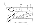
図1〜図3に、本発明の一実施形態に係る密封装置の構成を示す。図1は、本実施形態の密封装置1の概略断面図であり、図2は密封装置1の要部断面図であり、図3は図2のX−X断面図である。
(Configuration of sealing device)
1 to 3 show a configuration of a sealing device according to an embodiment of the present invention. FIG. 1 is a schematic cross-sectional view of a
この密封装置1は、互いに同心的に相対回転自在に組み付けられた2部材としてのハウジング2と軸3との間の環状隙間に装着されて、その環状隙間を密封し、油などの密封対象の漏れを防止するものである。
This
密封装置1は、ハウジング2に設けられた軸孔の内周面に嵌合される環状のシール本体5と、このシール本体5に嵌め合い剛性を付与する補強環4とを有して構成されている。
The
補強環4は、軸孔内周面に沿って設けられる円筒部4aと、円筒部4aの大気側A端部から径方向内向きに延びる内向きフランジ部4bとを有する断面L字状の金属製の環状部材である。
The reinforcing
シール本体5は、補強環4の円筒部4a外周面から、内向きフランジ部4bの大気側A端面および密封対象側O端面にわたり、一体的に焼付固定されたゴム状弾性体からなる。
The
シール本体5のうち、補強環4の円筒部4a外周面に固定された外周シール部6は、ハウジング2の軸孔内周面に対して所定の締代を有している。外周シール部6は、補強環4の円筒部4aからの嵌め合い剛性を受けて軸孔内周面にしっかりと固定されるとともに、軸孔内周面からの密封対象の漏れを防止する。なお、外周シール部6は必須の構成要件ではなく、補強環4の円筒部4aを直接軸孔内周面に嵌合させる構成(金属嵌合タイプ)も採用することができる。
Of the
一方、シール本体5の軸3側には、補強環4の内向きフランジ部4bの内端から密封対象側Oに向かって内径方向に延びるシールリップ7と、逆に大気側Aに向かって内径方向に延びるダストリップ8とが設けられている。
On the other hand, on the
ダストリップ8は、断面板状を呈しており、そのリップ先端が軸3の周面に摺動自在に密封接触するようになっている。これにより、大気側Aからのダストの侵入を防止している。
The dust lip 8 has a plate shape in cross section, and the tip of the lip is slidably sealed to the peripheral surface of the
シールリップ7は、密封対象側Oに臨む密封対象側傾斜面9と、大気側Aに臨む大気側傾斜面11と、これら密封対象側傾斜面9と大気側傾斜面11の間に配置される摺動面10と、を有している。
The sealing
シールリップ7の密封対象側傾斜面9は、摺動面10の密封対象側O端縁から密封対象側Oに向かって、軸3の周面との間隔を徐々に広げるように傾斜している。密封対象側傾斜面9の軸3の周面に対する傾斜角θ1(図2)は、45°±10°の範囲に設定するこ
とが好ましい。
The sealing target side inclined
他方、シールリップ7の大気側傾斜面11は、摺動面10の大気側A端縁から大気側Aに向かって、軸3の周面との間隔を徐々に広げるように傾斜している。大気側傾斜面11の軸3の周面に対する傾斜角θ2は、25°±10°の範囲に設定することが好ましい。
On the other hand, the atmosphere-side
そして、密封対象側傾斜面9と大気側傾斜面11との間に、軸3の周面に沿うようにして摺動面10が設けられている。すなわち、シールリップ7のリップ先端部は、密封対象側Oから大気側Aにかけて、密封対象側傾斜面9,摺動面10および大気側傾斜面11が連続的に形成されてなり、概略台形状の断面を呈するフラットタイプの摺動部を構成している。
A sliding
なお、摺動面10の軸3の周面に対する傾斜角θ3は、10°±10°の範囲に設定することが好ましい。つまり、摺動面10は、概ね軸3の周面に沿うものの、僅かながら大気側Aに向かって軸3の周面との間隔を徐々に広げるように傾斜して設けることが好ましい。ただし、θ3<θ2の関係は満たさなければならない。
Note that the inclination angle θ 3 of the sliding
上記構成のリップ先端部は、図1に示すように、軸3の周面に対して所定の締代を有している。したがって、密封装置1を軸3に装着した際には、シールリップ7が拡径するように弾性変形を受け、その弾性復元力により軸3の周面に摺動自在に密封接触することとなる。なお、シールリップ7の外周側であって摺動面10のちょうど背面となる位置には、リップ先端部に軸3への緊迫力を付与するガータースプリング14が装着されている。
As shown in FIG. 1, the tip end portion of the lip having the above configuration has a predetermined allowance with respect to the peripheral surface of the
(ネジ突起の構成)
本実施形態の密封装置1では、シールリップ7の大気側傾斜面11から摺動面10の中途にかけて第1ネジ突起12が設けられている。また、シールリップ7の摺動面10上には第2ネジ突起13が設けられている。第1ネジ突起12および第2ネジ突起13は、軸線に対して斜めになるように、互いに略平行に設けられる。
(Structure of screw protrusion)
In the
第1ネジ突起12は、概ね4つの部分から構成される。詳しくは、第1ネジ突起12は、密封対象側O(先端側)から順に、摺動面10に沿って切り欠かれたような形状を呈する切り欠き部12a、大気側傾斜面11上において大気側A(後端側)に行くに従って幅と高さが漸次増すような形状を呈する拡幅部12b、略等しい幅を保ったまま大気側Aに行くに従って高さが漸次増すような形状を呈する等幅部12c、および、幅と高さが急激に減少するように切り欠かれた形状を呈する後端部12dからなる。
The
切り欠き部12aは摺動面10上に設けられており、その先端は摺動面10の中程まで達している。切り欠き部12aの軸3の周面に対する角度θ4は、0°〜45°の範囲に設定することが好ましい。つまり、切り欠き部12aは、軸3の周面と略平行に設けるか、あるいは密封対象側Oに向かって軸3の周面との間隔を徐々に広げるように傾斜して設けることが好ましい。
The
拡幅部12b、等幅部12cおよび後端部12dは大気側傾斜面11上に設けられており、その後端は大気側傾斜面11の端縁近傍まで達している。拡幅部12bの断面形状は略三角形であるが、等幅部12cの断面形状は三角形の両裾が除かれたような略五角形をなす(図3参照)。
The widened
拡幅部12bから等幅部12cにかけては、第1ネジ突起12の稜線は滑らかに変化する。切り欠き部12aと拡幅部12bの間、および、等幅部12cと後端部12dの間では、稜線は不連続となるが、その内角はいずれも凸角(180°よりも小さい角)になっ
ている。
From the widened
上記構成の第1ネジ突起12の形状は、次のように捉えることもできる。図2に破線で示すように、摺動面10から大気側傾斜面11を横断しさらに大気側の位置まで延びる仮想的な舟底ネジ15を考える。第1ネジ突起12は、かかる舟底ネジ15の密封対象側O端部と大気側傾斜面11の端縁近傍の部分(舟底ネジ15の略中間部)とをそれぞれ切り欠くとともに、舟底ネジ15の幅が狭くなるように両側部を切り欠いたような形状を呈しているといえる。
The shape of the
一方、第2ネジ突起13は、摺動面10の大気側A端縁から密封対象側O端縁にかけて形成されている。第2ネジ突起13は、高さ・幅ともに略一定の平行ネジ形状を呈する。
On the other hand, the
軸3に略平行な摺動面10を有する所謂フラットリップについて、第2ネジ突起13の高さをいろいろに変えながらエアリーク試験を行ったところ、0.06mm以上ではエアリークの発生が認められた(ただし、試験条件は、エア圧:30kPa、偏心量:0mmTIR、温度:室温、初期潤滑:ドライである。)。従って、第2ネジ突起13の高さは0.05mm以下に設定することが好ましい。
When a so-called flat lip having a sliding
このような構成の密封装置1にあっては、初期作動時において、まず摺動面10、第1ネジ突起12の切り欠き部12aおよび第2ネジ突起13が軸3の周面に接触する。したがって、摺動面10による吸い込み効果と第1ネジ突起12および第2ネジ突起13によるネジポンプ効果により、良好なシール性を得ることができ、密封対象側Oからの密封対象の漏れを確実に防止することができる。
In the
また、長期作動時において第1ネジ突起12の先端部の摩耗が進行すると、摺動面10の接触幅が増大していくが、それに対応するように第1ネジ突起12の拡幅部12bそして等幅部12cが軸3の周面に接触するようになり、第1ネジ突起12の接触幅も増大する。なお、ここで「接触幅」とは、軸3の周面との接触面における軸方向の幅のことをさす。つまり、第1ネジ突起12の接触幅は、突起の幅と高さに依存する。
Further, when the wear of the tip end portion of the
第1ネジ突起12によるネジポンプ効果は摺動面10の接触幅と第1ネジ突起12の接触幅との比率により決定されるところ、本実施の形態の構成によれば摩耗の進行に伴って第1ネジ突起12の接触幅が増大していくので、長期作動時においてもシール性が低下することなく良好なシール性を維持することが可能となる。
The screw pump effect by the
このように、第1ネジ突起12を大気側傾斜面11および摺動面10に沿わせて設けたことで、切り欠き部12aにて初期的なシール性を確保でき、且つ、摩耗進行時にもシール性の低下を防止することができることから、初期的にも耐久的にも良好なシール性を長期にわたり発揮することが可能となる。
Thus, by providing the
しかも、第1ネジ突起12の等幅部12cが、略等しい幅を保ったまま大気側Aに行くに従って高さが増すような形状を有しているので、第1ネジ突起12の数を減らすことなくその高さを高くし、摩耗進行時におけるネジポンプ効果を向上させることができる。
In addition, since the
また、本実施形態では、リップ先端部の摺動部位が面(摺動面10)になっている所謂フラットリップを採用したため、従来のような楔形リップに比べ、初期作動時における締め付け圧を低減させることができる。これにより、リップ先端部の摩耗の進行が遅くなり、密封装置1の長寿命化を図ることができる。
Further, in this embodiment, a so-called flat lip in which the sliding portion of the lip tip portion is a surface (sliding surface 10) is adopted, so that the tightening pressure during the initial operation is reduced compared to a conventional wedge-shaped lip. Can be made. As a result, the progress of wear of the lip tip is delayed, and the life of the
(ネジ突起の作製方法)
さらに、本実施の形態の密封装置1によれば、上記構成を採用したことにより、成形型の加工および密封装置自体の加工の容易化を図ることもできる。以下、この点について詳しく説明する。
(Manufacturing method of screw protrusion)
Furthermore, according to the
一般に、ゴム状弾性体からなる密封装置は成形型にゴム生地を流し込み加硫成形して作製される。それゆえ、シールリップにネジ突起を設けるためには、あらかじめ成形型にネジ形状に合わせた窪みを形成しておく必要がある。 In general, a sealing device made of a rubber-like elastic body is produced by pouring a rubber cloth into a mold and vulcanization molding. Therefore, in order to provide the screw protrusion on the seal lip, it is necessary to form a depression in accordance with the screw shape in the mold in advance.
図8に示した2種類のネジ形状を組み合わせたネジ突起の場合、平行ネジ部に対応した窪みと舟底ネジ部に対応した窪みとを別々のカッターを用いて形成しなければならなかった(図10参照)。これは、平行ネジ部と舟底ネジ部との接続部分が不連続に接続されており、且つ、その接続部分の内角が凹角となっているからであって、一般に、このような凹角に対応する窪みを一回の切削で加工可能なカッターを作製することは極めて困難であることに起因する。 In the case of a screw projection combining two types of screw shapes shown in FIG. 8, the dent corresponding to the parallel screw part and the dent corresponding to the boat bottom screw part had to be formed using separate cutters ( (See FIG. 10). This is because the connecting portion between the parallel screw portion and the boat bottom screw portion is connected discontinuously, and the inner angle of the connecting portion is a concave angle, and generally corresponds to such a concave angle. This is because it is extremely difficult to produce a cutter that can process a recess to be cut by a single cutting.
これに対し、本実施形態の第1ネジ突起12の形状に対応する窪みは、刃先の端部に切り欠きを設けたカッターを用いることで、一度の加工により形成することが可能である。すなわち、平行ネジと舟底ネジを組み合わせたものと同様の作用効果を奏するネジ突起をより簡易に実現することができるのである。
On the other hand, the recess corresponding to the shape of the
具体的な成形型の加工方法について、図4を参照して説明する。図4は、成形型に第1ネジ突起12に対応する窪みを形成する際の様子を示す説明図である。
A specific method of processing the mold will be described with reference to FIG. FIG. 4 is an explanatory view showing a state in which a recess corresponding to the
カッター16の刃先は、先端側切り欠き部17a、弧状部17b、後端側切り欠き部17cから構成される。先端側切り欠き部17aと弧状部17bの接続部分、および、弧状部17bと後端側切り欠き部17cの接続部分の内角はいずれも凸角である。また両側の刃面18は山型をなす。このような刃先形状のカッター16の作製は比較的容易である。
The cutting edge of the
そして、かかるカッター16を成形型20に押し付け、第1ネジ突起12に対応した窪み21を形成する。このとき、先端側切り欠き部17aが第1ネジ突起12の切り欠き部12aに、弧状部17bが拡幅部12bおよび等幅部12cに、後端側切り欠き部17cが後端部12dに、それぞれ対応した凹形状を形成することになる。また、カッター16を押し付ける際に、弧状部17bにおいてカッター16の側面19を成形型20に所定量侵入させることで、等幅部12cに対応した略五角形断面の窪みを形成可能である。
And this
このように、本実施の形態の構成によれば、2種類の異なる形状のネジ部分を一回で成形型に刻み込むことが可能となり、成形型の加工工程の簡略化と容易化を図ることができる。 As described above, according to the configuration of the present embodiment, two types of differently shaped screw portions can be engraved into the molding die at a time, and the machining process of the molding die can be simplified and facilitated. it can.
また、第1ネジ突起12の切り欠き部12aおよび後端部12dを直線的に切り欠いた形状としたことにより、カッター16の加工が容易となるばかりでなく、カッター16を成形型20に押し付ける際に押し付け位置が多少軸方向にずれた場合であっても、第1ネジ突起12の切り欠き部12aの高さに影響を及ぼさず、加工精度に起因するシール性能のばらつきを抑えることができる。
Further, since the
さらに、リップ先端部を摺動面10により構成したことで、メスカット工程が不要となるため、モールド成形のみでシール本体を作製することが可能となり、密封装置自体の加工工程の簡略化と容易化を図ることもできる。
Furthermore, since the tip of the lip is constituted by the sliding
(変形例)
上記実施形態では、第1ネジ突起として弧状の稜線を有する舟底型のものを採用したが、第1ネジ突起の形状はこれに限られるものではなく、種々のネジ形状を採用することができる。その一例を図5に示す。
(Modification)
In the above-described embodiment, a boat bottom type having an arc-shaped ridge line is adopted as the first screw protrusion, but the shape of the first screw protrusion is not limited to this, and various screw shapes can be adopted. . An example is shown in FIG.
図5では、シールリップ7の大気側傾斜面11から摺動面10の中途にかけて、テーパ形状の第1ネジ突起22が設けられている。第1ネジ突起22は、高さおよび幅が大気側にいくほど大きくなるテーパ形状を基本形状としているが、摺動面10側の端部(切り欠き部22a)が軸の周面に沿って切り欠かれたような形状を呈している。また、第1ネジ突起22は、上記実施形態のものと同様、拡幅部22bおよび等幅部22cを有している。
In FIG. 5, a tapered
かかる形状の第1ネジ突起22の場合も、上記実施形態のものと同様の作用効果を奏することができる。
Even in the case of the
なお、上記実施形態および変形例は本発明の一具体例を例示したものにすぎない。本発明の範囲は上述した形状のものに限られるものではなく、その技術思想の範囲内で種々の変形が可能である。 The above-described embodiment and modification are merely examples of the present invention. The scope of the present invention is not limited to the shape described above, and various modifications are possible within the scope of the technical idea.
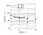
上記構成の密封装置の実施例と楔形リップの比較例1,2を用いて、ポンプ量の比較試験を実施した。 Using the example of the sealing device having the above-described configuration and the comparative examples 1 and 2 of the wedge-shaped lip, a pump amount comparison test was performed.
本実施例の密封装置は図1に示したものと同様である。本実施例では、軸径を80mm、摺動面10の軸方向長さを0.5mm、第1ネジ突起12の最大高さを240μm、第2ネジ突起13の高さを35μmに設定した。第1ネジ突起12および第2ネジ突起13は、それぞれシールリップ7の周面に等しい間隔で配置されている。
The sealing device of this embodiment is the same as that shown in FIG. In this example, the shaft diameter was set to 80 mm, the axial length of the sliding
比較例1は、図8に示した従来の密封装置であって、楔形リップ101の大気側摺動面102に、平行ネジと舟底ネジとを組み合わせた形状のネジ突起103を等配したものである。ここでは軸径を80mm、ネジ突起103の最大高さを180μmに設定した。
Comparative Example 1 is the conventional sealing device shown in FIG. 8, in which screw
図6に比較例2の密封装置を示す。比較例2は、楔形リップ101の大気側摺動面102に、平行ネジと舟底ネジとを組み合わせた形状のネジ突起110を等配したものである。ただし、比較例2では、舟底ネジの一部に実施例と同様の等幅部110aを設けることで、ネジ突起の最大高さ110を240μmにしている。軸径は80mmである。
FIG. 6 shows a sealing device of Comparative Example 2. In Comparative Example 2, screw
実施例、比較例1,2の3つの密封装置を軸封部に装着し、軸偏心:0.1mmTIR、取付偏心0.2mmTIR、油種:CD級10W−30、油温:120℃、油量:軸中心、回転速度:3000rpmという条件下でポンプ量を測定した。なお、試験時間はそれぞれの漏れ量に応じて適宜設定した。 Three sealing devices of Examples and Comparative Examples 1 and 2 are attached to the shaft seal, shaft eccentricity: 0.1 mm TIR, mounting eccentricity 0.2 mm TIR, oil type: CD class 10W-30, oil temperature: 120 ° C., oil The pump amount was measured under the conditions of amount: shaft center, rotation speed: 3000 rpm. The test time was appropriately set according to the amount of leakage.
ポンプ量の比較試験の結果を図7に示す。初期作動時の背面漏れ量を比較すると、比較例1,2に比べて本実施例のほうがポンプ量が向上していることがわかる。また、摩耗進行時の背面漏れ量を比較すると、比較例1,2に比べて本実施例のほうがポンプ量の低下が極めて少ない。すなわち、本実施例の構成を採用することによって、初期的にも耐久的にもネジポンプ効果による良好なシール性を長期にわたり発揮することができることがわかる。 The result of the pump amount comparison test is shown in FIG. Comparing the amount of back leakage at the time of initial operation, it can be seen that the pump amount is improved in this embodiment compared to Comparative Examples 1 and 2. Further, when comparing the back surface leakage amount during the progress of wear, the pump amount of the present example is much smaller than that of Comparative Examples 1 and 2. That is, by adopting the configuration of this example, it can be seen that good sealing performance due to the screw pump effect can be exhibited over a long period of time, both initially and in a durable manner.
1 密封装置
2 ハウジング
3 軸
4 補強環
4a 円筒部
4b 内向きフランジ部
5 シール本体
6 外周シール部
7 シールリップ
8 ダストリップ
9 密封対象側傾斜面
10 摺動面
11 大気側傾斜面
12 第1ネジ突起
12a 切り欠き部
12b 拡幅部
12c 等幅部
12d 後端部
13 第2ネジ突起
14 ガータースプリング
15 舟底ネジ
16 カッター
17a 先端側切り欠き部
17b 弧状部
17c 後端側切り欠き部
18 刃面
19 側面
20 成形型
21 窪み
22 第1ネジ突起
22a 切り欠き部
22b 拡幅部
22c 等幅部
A 大気側
O 密封対象側
DESCRIPTION OF
Claims (2)
前記シールリップは、
前記周面に沿う摺動面と、
前記摺動面の大気側端縁から前記周面との間隔を徐々に広げるように傾斜する傾斜面と、
前記傾斜面から前記摺動面の中途にかけて設けられる第1ネジ突起と、
前記摺動面上に設けられる第2ネジ突起と、
を備え、
前記第1ネジ突起の摺動面側の端部は、摺動面に沿って切り欠かれたような形状を呈し、
前記第1ネジ突起の傾斜面側の部分は、略等しい幅を保ったまま大気側に行くに従って高さが増すような形状の等幅部を有する
ことを特徴とする密封装置。 In a sealing device that seals an annular gap between two members assembled so as to be relatively rotatable, and includes a seal lip that slides on a peripheral surface of one of the two members,
The seal lip is
A sliding surface along the circumferential surface;
An inclined surface that inclines so as to gradually widen the gap between the peripheral surface and the atmosphere side edge of the sliding surface;
A first screw protrusion provided from the inclined surface to the middle of the sliding surface;
A second screw protrusion provided on the sliding surface;
With
The end of the first screw protrusion on the sliding surface side has a shape that is cut out along the sliding surface,
A portion on the inclined surface side of the first screw projection has a uniform width portion having a shape that increases in height toward the atmosphere side while maintaining a substantially equal width.
The sealing device according to claim 1, wherein the equal-width portion has a substantially pentagonal cross-sectional shape in which both hems of a triangle are removed.
Priority Applications (7)
| Application Number | Priority Date | Filing Date | Title |
|---|---|---|---|
| JP2003410490A JP2005172061A (en) | 2003-12-09 | 2003-12-09 | Sealing device |
| PCT/JP2004/017847 WO2005057058A1 (en) | 2003-12-09 | 2004-12-01 | Sealing device |
| US10/582,346 US7506875B2 (en) | 2003-12-09 | 2004-12-01 | Sealing device |
| CN2008100837415A CN101239492B (en) | 2003-12-09 | 2004-12-01 | Method for processing forming mould |
| EP04820150.3A EP1698809B1 (en) | 2003-12-09 | 2004-12-01 | Sealing device |
| CNB2004800368272A CN100436896C (en) | 2003-12-09 | 2004-12-01 | Sealing device |
| KR1020067012527A KR100898449B1 (en) | 2003-12-09 | 2004-12-01 | Sealing device |
Applications Claiming Priority (1)
| Application Number | Priority Date | Filing Date | Title |
|---|---|---|---|
| JP2003410490A JP2005172061A (en) | 2003-12-09 | 2003-12-09 | Sealing device |
Publications (1)
| Publication Number | Publication Date |
|---|---|
| JP2005172061A true JP2005172061A (en) | 2005-06-30 |
Family
ID=34674936
Family Applications (1)
| Application Number | Title | Priority Date | Filing Date |
|---|---|---|---|
| JP2003410490A Pending JP2005172061A (en) | 2003-12-09 | 2003-12-09 | Sealing device |
Country Status (6)
| Country | Link |
|---|---|
| US (1) | US7506875B2 (en) |
| EP (1) | EP1698809B1 (en) |
| JP (1) | JP2005172061A (en) |
| KR (1) | KR100898449B1 (en) |
| CN (2) | CN100436896C (en) |
| WO (1) | WO2005057058A1 (en) |
Cited By (5)
| Publication number | Priority date | Publication date | Assignee | Title |
|---|---|---|---|---|
| JP2007064458A (en) * | 2005-09-02 | 2007-03-15 | Nok Corp | Oil seal |
| JP2007225064A (en) * | 2006-02-24 | 2007-09-06 | Koyo Sealing Techno Co Ltd | Sealing device |
| WO2008126478A1 (en) * | 2007-04-11 | 2008-10-23 | Nok Corporation | Oil seal |
| WO2016181900A1 (en) * | 2015-05-11 | 2016-11-17 | Nok株式会社 | Sealing device |
| WO2022059360A1 (en) * | 2020-09-15 | 2022-03-24 | Nok株式会社 | Sealing device |
Families Citing this family (19)
| Publication number | Priority date | Publication date | Assignee | Title |
|---|---|---|---|---|
| JP4366897B2 (en) * | 2002-02-28 | 2009-11-18 | Nok株式会社 | Mold processing method |
| JP2008057756A (en) * | 2006-09-04 | 2008-03-13 | Kayaba Ind Co Ltd | Oil seal for reciprocating |
| DE102007036625B4 (en) * | 2007-08-02 | 2013-10-17 | Ab Skf | sealing element |
| WO2009031199A1 (en) * | 2007-09-04 | 2009-03-12 | Arai Seisakusho Co., Ltd. | Hermetic sealing device |
| WO2010006364A1 (en) * | 2008-07-14 | 2010-01-21 | Weir Minerals Australia Ltd | A sealing member for providing sealing between components of a rotary machine |
| CN102121535A (en) * | 2010-01-08 | 2011-07-13 | 刘荣春 | Disassembling-free skeleton-free shaft oil seal and seal maintaining operation process of speed reduction box |
| DE102010042555B4 (en) * | 2010-10-18 | 2015-10-08 | Aktiebolaget Skf | Radial shaft seal |
| DE102011002491A1 (en) * | 2011-01-11 | 2012-07-12 | Aktiebolaget Skf | Radial shaft seal |
| WO2012132731A1 (en) * | 2011-03-31 | 2012-10-04 | イーグル工業株式会社 | Sealing device and sealing structure |
| US9062774B2 (en) | 2012-03-21 | 2015-06-23 | Federal-Mogul Corporation | Radial shaft seal with static and hydrodynamic sealing features |
| JP5637172B2 (en) * | 2012-04-27 | 2014-12-10 | Nok株式会社 | Sealing device |
| DE102013207029B4 (en) * | 2013-04-18 | 2016-05-04 | Aktiebolaget Skf | Radial shaft seal arrangement |
| JP6177582B2 (en) * | 2013-05-14 | 2017-08-09 | Nok株式会社 | Sealing device |
| JP6231352B2 (en) * | 2013-10-29 | 2017-11-15 | Nok株式会社 | Oil seal |
| CN107002878B (en) * | 2014-11-18 | 2018-10-02 | Nok株式会社 | Sealing structure |
| CN107461496B (en) * | 2016-06-06 | 2021-01-29 | 舍弗勒技术股份两合公司 | Sealing member and rotating assembly |
| JP6809847B2 (en) * | 2016-09-01 | 2021-01-06 | Nok株式会社 | Sealing device |
| EP3825586A4 (en) * | 2018-07-17 | 2021-09-08 | NOK Corporation | Sealing device |
| JP2020041553A (en) * | 2018-09-06 | 2020-03-19 | Nok株式会社 | Sealing device |
Citations (3)
| Publication number | Priority date | Publication date | Assignee | Title |
|---|---|---|---|---|
| JPH1019135A (en) * | 1996-07-02 | 1998-01-23 | Koyo Shikagoroohaido Kk | Oil seal |
| JP2000310338A (en) * | 1999-04-23 | 2000-11-07 | Nok Corp | Sealing device |
| JP2003254439A (en) * | 2002-02-28 | 2003-09-10 | Nok Corp | Sealing device |
Family Cites Families (8)
| Publication number | Priority date | Publication date | Assignee | Title |
|---|---|---|---|---|
| GB1219272A (en) | 1967-05-30 | 1971-01-13 | Dunlop Co Ltd | Improvements in sealing rings |
| DE2556992C2 (en) | 1975-12-18 | 1980-04-24 | Goetze Ag, 5093 Burscheid | Shaft seal |
| US5104603A (en) * | 1988-08-05 | 1992-04-14 | Nok Corporation | Method of manufacturing sealing apparatus and mold |
| JP3278349B2 (en) | 1995-05-25 | 2002-04-30 | エヌオーケー株式会社 | Sealing device |
| JPH11311338A (en) | 1998-02-27 | 1999-11-09 | Nok Corp | Oil seal |
| EP0939257A3 (en) * | 1998-02-27 | 2000-05-31 | NOK Corporation | Oil seal |
| JP2000065216A (en) * | 1998-08-12 | 2000-03-03 | Nok Corp | Sealing device |
| CN2388421Y (en) * | 1998-08-14 | 2000-07-19 | 十堰东森汽车密封件有限公司 | Dynamic rotation axis grease seal with two-way oil return line |
-
2003
- 2003-12-09 JP JP2003410490A patent/JP2005172061A/en active Pending
-
2004
- 2004-12-01 WO PCT/JP2004/017847 patent/WO2005057058A1/en active Application Filing
- 2004-12-01 EP EP04820150.3A patent/EP1698809B1/en not_active Expired - Fee Related
- 2004-12-01 CN CNB2004800368272A patent/CN100436896C/en not_active Expired - Fee Related
- 2004-12-01 KR KR1020067012527A patent/KR100898449B1/en active IP Right Grant
- 2004-12-01 CN CN2008100837415A patent/CN101239492B/en not_active Expired - Fee Related
- 2004-12-01 US US10/582,346 patent/US7506875B2/en active Active
Patent Citations (3)
| Publication number | Priority date | Publication date | Assignee | Title |
|---|---|---|---|---|
| JPH1019135A (en) * | 1996-07-02 | 1998-01-23 | Koyo Shikagoroohaido Kk | Oil seal |
| JP2000310338A (en) * | 1999-04-23 | 2000-11-07 | Nok Corp | Sealing device |
| JP2003254439A (en) * | 2002-02-28 | 2003-09-10 | Nok Corp | Sealing device |
Cited By (10)
| Publication number | Priority date | Publication date | Assignee | Title |
|---|---|---|---|---|
| JP2007064458A (en) * | 2005-09-02 | 2007-03-15 | Nok Corp | Oil seal |
| JP2007225064A (en) * | 2006-02-24 | 2007-09-06 | Koyo Sealing Techno Co Ltd | Sealing device |
| WO2008126478A1 (en) * | 2007-04-11 | 2008-10-23 | Nok Corporation | Oil seal |
| JP5168514B2 (en) * | 2007-04-11 | 2013-03-21 | Nok株式会社 | Oil seal |
| US8413995B2 (en) | 2007-04-11 | 2013-04-09 | Nok Corporation | Oil seal |
| WO2016181900A1 (en) * | 2015-05-11 | 2016-11-17 | Nok株式会社 | Sealing device |
| JPWO2016181900A1 (en) * | 2015-05-11 | 2018-03-08 | Nok株式会社 | Sealing device |
| RU2673949C1 (en) * | 2015-05-11 | 2018-12-03 | Нок Корпорейшн | Sealing device |
| US10605368B2 (en) | 2015-05-11 | 2020-03-31 | Nok Corporation | Sealing apparatus |
| WO2022059360A1 (en) * | 2020-09-15 | 2022-03-24 | Nok株式会社 | Sealing device |
Also Published As
| Publication number | Publication date |
|---|---|
| EP1698809B1 (en) | 2019-04-03 |
| US7506875B2 (en) | 2009-03-24 |
| EP1698809A4 (en) | 2014-09-03 |
| US20070182104A1 (en) | 2007-08-09 |
| KR20060113968A (en) | 2006-11-03 |
| EP1698809A1 (en) | 2006-09-06 |
| CN100436896C (en) | 2008-11-26 |
| KR100898449B1 (en) | 2009-05-21 |
| CN1890495A (en) | 2007-01-03 |
| WO2005057058A1 (en) | 2005-06-23 |
| CN101239492A (en) | 2008-08-13 |
| CN101239492B (en) | 2011-07-13 |
Similar Documents
| Publication | Publication Date | Title |
|---|---|---|
| JP2005172061A (en) | Sealing device | |
| US7645412B2 (en) | Sealing device | |
| JP2017150674A (en) | Seal ring | |
| JPH08178077A (en) | Sealing device | |
| JPH0942463A (en) | Sealing device | |
| JP2008185080A (en) | Sealing device | |
| JP3180285B2 (en) | Oil seal | |
| JP6942431B2 (en) | mechanical seal | |
| JPH1019135A (en) | Oil seal | |
| JP2011080497A (en) | Seal ring for rolling bearing and rolling bearing with seal ring | |
| JPH11311338A (en) | Oil seal | |
| JP7163491B2 (en) | sealing device | |
| JP2001027326A (en) | Oil seal | |
| JP4240217B2 (en) | Sealing device | |
| JP2006162015A (en) | Sealing device | |
| JP2002206644A (en) | Sealing device | |
| JP5055978B2 (en) | Seal ring and seal structure | |
| JP2004251442A (en) | Sealing device | |
| JPH0996364A (en) | X-ring | |
| JPH11280916A (en) | Rotary shaft seal | |
| JP2002206645A (en) | Sealing device | |
| JP2009041612A (en) | Oil seal | |
| JPH11257287A (en) | Wear ring structure of centrifugal pump | |
| JP2012112456A (en) | Die for oil seal | |
| JP2001173798A (en) | Oil seal with screw |
Legal Events
| Date | Code | Title | Description |
|---|---|---|---|
| A621 | Written request for application examination |
Free format text: JAPANESE INTERMEDIATE CODE: A621 Effective date: 20060906 |
|
| A131 | Notification of reasons for refusal |
Free format text: JAPANESE INTERMEDIATE CODE: A131 Effective date: 20100119 |
|
| A521 | Written amendment |
Free format text: JAPANESE INTERMEDIATE CODE: A523 Effective date: 20100315 |
|
| A131 | Notification of reasons for refusal |
Free format text: JAPANESE INTERMEDIATE CODE: A131 Effective date: 20100928 |
|
| A02 | Decision of refusal |
Free format text: JAPANESE INTERMEDIATE CODE: A02 Effective date: 20110419 |