JP5637172B2 - Sealing device - Google Patents
Sealing device Download PDFInfo
- Publication number
- JP5637172B2 JP5637172B2 JP2012102102A JP2012102102A JP5637172B2 JP 5637172 B2 JP5637172 B2 JP 5637172B2 JP 2012102102 A JP2012102102 A JP 2012102102A JP 2012102102 A JP2012102102 A JP 2012102102A JP 5637172 B2 JP5637172 B2 JP 5637172B2
- Authority
- JP
- Japan
- Prior art keywords
- screw
- protrusion
- atmosphere
- lip end
- sealing device
- Prior art date
- Legal status (The legal status is an assumption and is not a legal conclusion. Google has not performed a legal analysis and makes no representation as to the accuracy of the status listed.)
- Active
Links
Images


Classifications
-
- F—MECHANICAL ENGINEERING; LIGHTING; HEATING; WEAPONS; BLASTING
- F16—ENGINEERING ELEMENTS AND UNITS; GENERAL MEASURES FOR PRODUCING AND MAINTAINING EFFECTIVE FUNCTIONING OF MACHINES OR INSTALLATIONS; THERMAL INSULATION IN GENERAL
- F16J—PISTONS; CYLINDERS; SEALINGS
- F16J15/00—Sealings
- F16J15/16—Sealings between relatively-moving surfaces
- F16J15/32—Sealings between relatively-moving surfaces with elastic sealings, e.g. O-rings
- F16J15/3244—Sealings between relatively-moving surfaces with elastic sealings, e.g. O-rings with hydrodynamic pumping action
-
- F—MECHANICAL ENGINEERING; LIGHTING; HEATING; WEAPONS; BLASTING
- F16—ENGINEERING ELEMENTS AND UNITS; GENERAL MEASURES FOR PRODUCING AND MAINTAINING EFFECTIVE FUNCTIONING OF MACHINES OR INSTALLATIONS; THERMAL INSULATION IN GENERAL
- F16J—PISTONS; CYLINDERS; SEALINGS
- F16J15/00—Sealings
- F16J15/16—Sealings between relatively-moving surfaces
- F16J15/32—Sealings between relatively-moving surfaces with elastic sealings, e.g. O-rings
- F16J15/3204—Sealings between relatively-moving surfaces with elastic sealings, e.g. O-rings with at least one lip
-
- F—MECHANICAL ENGINEERING; LIGHTING; HEATING; WEAPONS; BLASTING
- F16—ENGINEERING ELEMENTS AND UNITS; GENERAL MEASURES FOR PRODUCING AND MAINTAINING EFFECTIVE FUNCTIONING OF MACHINES OR INSTALLATIONS; THERMAL INSULATION IN GENERAL
- F16J—PISTONS; CYLINDERS; SEALINGS
- F16J15/00—Sealings
- F16J15/16—Sealings between relatively-moving surfaces
- F16J15/32—Sealings between relatively-moving surfaces with elastic sealings, e.g. O-rings
- F16J15/3268—Mounting of sealing rings
-
- F—MECHANICAL ENGINEERING; LIGHTING; HEATING; WEAPONS; BLASTING
- F16—ENGINEERING ELEMENTS AND UNITS; GENERAL MEASURES FOR PRODUCING AND MAINTAINING EFFECTIVE FUNCTIONING OF MACHINES OR INSTALLATIONS; THERMAL INSULATION IN GENERAL
- F16J—PISTONS; CYLINDERS; SEALINGS
- F16J15/00—Sealings
- F16J15/16—Sealings between relatively-moving surfaces
- F16J15/32—Sealings between relatively-moving surfaces with elastic sealings, e.g. O-rings
- F16J15/3284—Sealings between relatively-moving surfaces with elastic sealings, e.g. O-rings characterised by their structure; Selection of materials
Landscapes
- Engineering & Computer Science (AREA)
- General Engineering & Computer Science (AREA)
- Mechanical Engineering (AREA)
- Physics & Mathematics (AREA)
- Fluid Mechanics (AREA)
- Sealing With Elastic Sealing Lips (AREA)
- Sealing Devices (AREA)
- Transmission Devices (AREA)
Description
本発明は、シール技術に係る密封装置に関する。本発明の密封装置は例えば、自動車関連の分野で用いられ、または汎用機械の分野などで用いられる。 The present invention relates to a sealing device according to a sealing technique. The sealing device of the present invention is used, for example, in the field of automobiles or in the field of general-purpose machines.
従来から図7に示すように、シールリップ51のポンプ量増大を目的として、シールリップ51の大気側斜面52に密封流体に対するポンプ作用を発揮するネジ53を設けた密封装置が知られている。
Conventionally, as shown in FIG. 7, for the purpose of increasing the pump amount of the
しかしながら、このようなネジ53付きの密封装置において、大気側Yの外部ダストがネジ53間に侵入すると、侵入したダストは回転軸55の回転に連れ回って円周方向へ移動し、移動したダストはネジ53に接触し、接触したダストはネジ53に沿ってリップ端54のほうへ向けて移動する。したがってその結果として、ダストがリップ端54および軸55間に噛み込み、リップ端54および軸55間に隙間が発生し、この隙間から密封流体(オイルなど)が漏れると云う不具合が懸念される。
However, in such a sealing device with the
本発明は以上の点に鑑みて、大気側の外部ダストがリップ端のほうへ侵入するのを抑制することができ、もってダストの噛み込みによる密封流体の漏れを抑制することができる密封装置を提供することを目的とする。 In view of the above points, the present invention provides a sealing device that can suppress external dust on the atmosphere side from entering the lip end, and thus can suppress leakage of the sealing fluid due to dust biting. The purpose is to provide.
上記目的を達成するため、本発明の請求項1による密封装置は、機内側の密封流体が大気側へ漏洩するのを抑制する密封装置であって、シールリップのリップ端にて軸に接触するとともに前記シールリップの大気側斜面に前記密封流体に対するポンプ作用を発揮するネジを円周上複数設けた密封装置において、大気側の外部ダストが前記リップ端のほうへ侵入するのを抑制すべく前記ネジ間にダスト侵入防止用の立体形状を設け、前記立体形状は、前記リップ端と平行な方向に延びる突起または溝よりなり、前記突起または溝は、その長手方向両端部がそれぞれ前記ネジに連続しており、前記突起は、その頂点が大気側に寄った略三角断面形状であり、前記溝は、その底点がリップ端側に寄った略三角断面形状であることを特徴とする。 In order to achieve the above object, a sealing device according to claim 1 of the present invention is a sealing device that suppresses leakage of a sealing fluid inside the machine to the atmosphere side, and contacts the shaft at the lip end of the sealing lip. In addition, in the sealing device in which a plurality of screws on the circumference are provided on the atmosphere-side slope of the seal lip so as to exert a pumping action on the sealing fluid, the atmosphere-side external dust is prevented from entering the lip end. A three-dimensional shape for preventing dust intrusion is provided between the screws, and the three-dimensional shape includes protrusions or grooves extending in a direction parallel to the lip end, and both ends of the protrusions or grooves are continuous with the screws. The protrusion has a substantially triangular cross-sectional shape whose apex approaches the atmosphere side, and the groove has a substantially triangular cross-sectional shape whose bottom point approaches the lip end side.
また、本発明の請求項2による密封装置は、機内側の密封流体が大気側へ漏洩するのを抑制する密封装置であって、シールリップのリップ端にて軸に接触するとともに前記シールリップの大気側斜面に前記密封流体に対するポンプ作用を発揮するネジを円周上複数設けた密封装置において、大気側の外部ダストが前記リップ端のほうへ侵入するのを抑制すべく前記ネジ間にダスト侵入防止用の立体形状を設け、前記立体形状は、前記リップ端と平行な方向に延びる突起または溝よりなり、前記突起または溝は、その長手方向両端部がそれぞれ前記ネジに連続しており、前記突起は、略三角または四角断面形状であり、前記突起の大気側の面は前記軸と直角ないし前記大気側斜面と直角の角度範囲に設定され、前記溝は、略三角または四角断面形状であり、前記溝のリップ端側の面は前記軸と直角ないし前記大気側斜面と直角の角度範囲に設定されていることを特徴とする。 The sealing device according to claim 2 of the present invention is a sealing device that suppresses leakage of the sealing fluid inside the machine to the atmosphere side, and is in contact with the shaft at the lip end of the seal lip and the seal lip. In a sealing device provided with a plurality of circumferentially provided screws that exert a pumping action on the sealing fluid on the atmosphere side slope, dust intrudes between the screws in order to suppress the outside dust on the atmosphere side from entering the lip end. A three-dimensional shape for prevention is provided, and the three-dimensional shape is composed of protrusions or grooves extending in a direction parallel to the lip end, and the protrusions or grooves each have both longitudinal ends thereof continuous to the screws, The protrusion has a substantially triangular or square cross-sectional shape, and the atmosphere-side surface of the protrusion is set to an angle range that is perpendicular to the axis or perpendicular to the atmosphere-side slope, and the groove has a substantially triangular or square cross-section. Is Jo, the surface of the lip end of the groove, characterized in that it is set to an angular range of perpendicular to the axis perpendicular to the air-side slope.
更にまた、本発明の請求項3による密封装置は、上記した請求項1または2記載の密封装置において、前記ネジはそれぞれ、前記リップ端近傍に設けられた断面均一の平行ネジと、前記平行ネジから連続して設けられた舟底形ネジとよりなり、前記立体形状は、前記平行ネジおよび舟底形ネジの接続部または前記平行ネジに連続するよう設けられた第1立体形状の突起と、前記舟底形ネジに連続するように設けられた第2立体形状の突起とよりなり、前記平行ネジの高さをh3、前記舟底形ネジの最大高さをh4、前記第1立体形状の突起の高さをh5、前記第2立体形状の突起の高さをh6として、
h5<h3≦h6<h4
の関係を充足することを特徴とする。
Furthermore, the sealing device according to claim 3 of the present invention is the sealing device according to claim 1 or 2 , wherein the screws are each a parallel screw having a uniform cross section provided in the vicinity of the lip end and the parallel screw. And the three-dimensional shape is a connecting portion of the parallel screw and the boat bottom-shaped screw or a first solid-shaped projection provided to be continuous with the parallel screw, It is composed of a projection of a second three-dimensional shape provided so as to be continuous with the boat bottom screw, the height of the parallel screw is h 3 , the maximum height of the boat bottom screw is h 4 , and the first solid The height of the protrusion of the shape is h 5 , and the height of the protrusion of the second three-dimensional shape is h 6 ,
h 5 <h 3 ≦ h 6 <h 4
It is characterized by satisfying the relationship.
上記構成を備える本発明の密封装置においては、大気側の外部ダストがリップ端のほうへ侵入するのを抑制すべく互いに隣り合うネジ間にダスト侵入防止用の立体形状が設けられているために、この立体形状が、大気側のダストがリップ端のほうへ侵入するのを抑制する機能を発揮する。立体形状は、リップ端と平行な方向に延びる突起または溝よりなり、突起はダストを堰き止め、溝はダストを収容するため、いずれの場合もダストがリップ端のほうへ侵入するのを抑制することが可能とされる。突起または溝は、その長手方向両端部がそれぞれネジに連続しているため、これらとネジとの間をダストが通過することはない。 In the sealing device of the present invention having the above-described configuration, a three-dimensional shape for preventing dust intrusion is provided between the screws adjacent to each other in order to prevent external dust on the air side from entering the lip end. This three-dimensional shape exerts a function of suppressing atmospheric dust from entering the lip end. The three-dimensional shape consists of protrusions or grooves extending in a direction parallel to the lip end, the protrusions dam the dust, and the grooves contain the dust, so that in all cases the dust is prevented from entering the lip end. It is possible. Since both ends of the protrusions or the grooves in the longitudinal direction are continuous with the screws, dust does not pass between these and the screws.
立体形状が突起の場合、突起の断面形状は特に限定されないが、例えば略三角断面形状とする。この場合、三角は正三角形や二等辺三角形でも良いが、頂点が大気側に寄った不等辺三角形にすると、大気側の面の仰角が大きく設定されるため、この大気側の面をダストが乗り越えにくい。 When the three-dimensional shape is a protrusion, the cross-sectional shape of the protrusion is not particularly limited. In this case, the triangle may be an equilateral triangle or an isosceles triangle. However, if the apex of the triangle is an unequal triangle with the apex approaching the atmosphere side, the elevation angle of the atmosphere side surface is set large. Hateful.
また、突起の断面形状を略三角または四角断面形状とするとともにその大気側の面を軸と直角ないし大気側斜面と直角の角度範囲内に設定しても良く、この場合も大気側の面の仰角が大きく設定されるため、大気側の面をダストが乗り越えにくい。 Also, the cross-sectional shape of the protrusion may be a substantially triangular or quadrangular cross-sectional shape, and the atmosphere side surface may be set within an angle range perpendicular to the axis or to the atmosphere side slope. Since the elevation angle is set large, dust is difficult to get over the atmosphere side surface.
立体形状が溝の場合、溝の断面形状は特に限定されないが、例えば略三角断面形状とする。三角は正三角形や二等辺三角形でも良いが、底点がリップ端側に寄った不等辺三角形にすると、リップ端側の面の伏角が大きく設定されるため、このリップ端側の面をダストが乗り越えにくい。 When the three-dimensional shape is a groove, the cross-sectional shape of the groove is not particularly limited. The triangle may be an equilateral triangle or an isosceles triangle, but if the base point is an unequal triangle with the base point close to the lip end, the dip end surface has a large dip angle, so dust is applied to the lip end surface. It is difficult to get over.
また、溝の断面形状を略三角または四角断面形状とするとともにそのリップ端側の面を軸と直角ないし大気側斜面と直角の角度範囲内に設定しても良く、この場合もリップ端側の面の伏角が大きく設定されるため、リップ端側の面をダストが乗り越えにくい。 In addition, the cross-sectional shape of the groove may be a substantially triangular or quadrangular cross-sectional shape, and the surface on the lip end side may be set within an angle range perpendicular to the axis or perpendicular to the atmosphere-side slope. Since the dip angle of the surface is set large, it is difficult for dust to get over the surface on the lip end side.
ネジは、スパイラル状の突起であるが、これを例えば、リップ端近傍に設けられた断面均一の平行ネジと、この平行ネジから連続して設けられた舟底形ネジとよりなるものとする。また立体形状を、平行ネジと舟底形ネジとの接続部または平行ネジに連続するよう設けられた第1立体形状の突起と、舟底形ネジに連続するように設けられた第2立体形状の突起とよりなるものとする。この場合、平行ネジの高さをh3、舟底形ネジの最大高さをh4、第1立体形状の突起の高さをh5、第2立体形状の突起の高さをh6として、
h5<h3≦h6<h4・・・・(a)式
の関係を充足すると、対応する位置関係にあるネジのほうが突起より高いため、ネジによるポンプ作用を十分に持続させることが可能とされる。舟底形ネジは、その高さおよび幅が長手方向の中央部で最も大きく、両端へ向けて徐々に縮小される形状である。
The screw is a spiral projection, and is composed of, for example, a parallel screw having a uniform cross section provided in the vicinity of the lip end, and a boat bottom screw provided continuously from the parallel screw. Further, the three-dimensional shape is a connection portion between the parallel screw and the boat bottom-shaped screw or a first three-dimensional shape protrusion provided so as to be continuous with the parallel screw, and a second three-dimensional shape provided so as to be continuous with the boat bottom-shaped screw. It shall consist of a protrusion. In this case, the height of the parallel screw is h 3 , the maximum height of the boat bottom shaped screw is h 4 , the height of the first three-dimensional shape projection is h 5 , and the height of the second three-dimensional shape projection is h 6. ,
h 5 <h 3 ≦ h 6 <h 4 ... ( 4 ) If the relationship of the formula (a) is satisfied, the screw in the corresponding positional relationship is higher than the protrusion, so that the pumping action by the screw can be sustained sufficiently. It is possible. The boat-bottomed screw has a shape such that its height and width are the largest in the central portion in the longitudinal direction and are gradually reduced toward both ends.
本発明は、以下の効果を奏する。 The present invention has the following effects.
すなわち、本発明においては上記したように、大気側のダストがリップ端のほうへ侵入するのを抑制すべくネジ間にダスト侵入防止用の立体形状が設けられているため、この立体形状が、大気側のダストがリップ端のほうへ侵入するのを抑制する機能を発揮する。立体形状が突起の場合はダストを堰き止めるとともに溝の場合はダストを収容するため、いずれの場合もダストがリップ端のほうへ侵入するのを抑制する。突起または溝は、その長手方向端部がネジに連続しているため、これらとネジとの間をダストが通過することはない。したがって以上のことから本発明所期の目的どおり、大気側のダストがリップ端のほうへ侵入するのを抑制し、もってダストの噛み込みによる密封流体の漏れを抑制する密封装置を提供することができる。 That is, as described above in the present invention, a three-dimensional shape for preventing dust intrusion is provided between the screws in order to suppress the dust on the air side from entering the lip end. Demonstrates the function of suppressing the dust on the atmosphere side from entering the lip edge. In the case where the three-dimensional shape is a protrusion, dust is dammed and in the case of a groove, dust is accommodated, and in any case, the dust is prevented from entering the lip end. Since the protrusion or groove has a longitudinal end continuous with the screw, dust does not pass between these and the screw. Therefore, as described above, according to the intended purpose of the present invention, it is possible to provide a sealing device that suppresses the entry of dust on the atmosphere side toward the lip end and thereby suppresses leakage of the sealing fluid due to the biting of dust. it can.
また、立体形状の突起を頂点が大気側に寄った略三角断面形状とすることにより、突起の大気側の面をダストが乗り越えにくくすることができ、立体形状の溝を底点がリップ端側に寄った略三角断面形状とすることにより、溝のリップ端側の面をダストが乗り越えにくくすることができる。 In addition, by making the three-dimensional protrusion a substantially triangular cross-sectional shape with the apex approaching the atmosphere side, it is possible to make it difficult for dust to get over the air-side surface of the protrusion, and the bottom of the three-dimensional groove is on the lip end side. By adopting a substantially triangular cross-sectional shape close to the groove, it is possible to make it difficult for dust to get over the surface on the lip end side of the groove.
また、立体形状の突起を略三角または四角断面形状とするとともに突起の大気側の面を軸と直角ないし大気側斜面と直角の角度範囲に設定することにより、突起の大気側の面をダストが乗り越えにくくすることができ、立体形状の溝を略三角または四角断面形状とするとともに溝のリップ端側の面を軸と直角ないし大気側斜面と直角の角度範囲に設定することにより、溝のリップ端側の面をダストが乗り越えにくくすることができる。 In addition, by making the three-dimensional protrusion into a substantially triangular or square cross-sectional shape and setting the atmosphere-side surface of the protrusion to an angle range perpendicular to the axis or perpendicular to the atmosphere-side slope, dust on the atmosphere-side surface of the protrusion By making the three-dimensional groove into a substantially triangular or square cross-sectional shape and setting the surface on the lip end side of the groove to an angle range perpendicular to the axis or to the atmospheric side slope, the groove lip It is possible to make it difficult for dust to get over the end surface.
また、平行ネジ、舟底形ネジ、第1立体形状の突起および第2立体形状の突起の各高さを上記(a)式に則って設定することにより、ネジによるポンプ作用の発揮と突起によるダスト侵入の抑制とを両立させることができる。 In addition, by setting the heights of the parallel screw, the boat bottom screw, the first three-dimensional shape protrusion, and the second three-dimensional shape protrusion in accordance with the above formula (a), the pump action by the screw and the protrusion It is possible to achieve both suppression of dust intrusion.
本発明には、以下の実施形態が含まれる。
(1)構成
(1−1)主リップの回転軸との封止面の近傍から大気側斜面に、周状に複数のネジを形成する。
(1−2)ネジ形状は、封止面近傍が断面均一の平行ネジから大気側へ向かって舟底形ネジに変わる。
(1−3)平行ネジ位置、ネジ形状が変わる位置、あるいは舟底形ネジ位置と交差するように、封止面と平行な環状の堰を設ける。
(1−4)堰は、頂点が大気側に寄った略三角断面形状で、高さは前記ネジより低い。
(1−5)堰は、突起であるが、溝でも良い。溝でもダスト回収効果が期待できる。
The present invention includes the following embodiments.
(1) Configuration (1-1) A plurality of screws are circumferentially formed on the atmosphere-side slope from the vicinity of the sealing surface with the rotation axis of the main lip.
(1-2) The screw shape changes from a parallel screw having a uniform cross-section in the vicinity of the sealing surface to a boat bottom screw toward the atmosphere.
(1-3) An annular weir parallel to the sealing surface is provided so as to intersect the parallel screw position, the position where the screw shape changes, or the boat bottom-shaped screw position.
(1-4) The weir has a substantially triangular cross-sectional shape with the apex approaching the atmosphere side, and the height is lower than that of the screw.
(1-5) The weir is a protrusion, but may be a groove. Dust recovery effect can be expected even in grooves.
(2)効果
(2−1)大気側から侵入したダスト等を堰によって堰き止めて、封止面側に近付けさせない。
(2−2)堰の頂点が大気側に寄った略三角断面形状であるため、ダスト等が堰を乗り越えにくい。
(2−3)堰の高さがネジより低いため、ポンプ量は維持しつつダストが主リップ先端に近付きにくくなる。
(2−4)舟底形ネジ部に堰を設ける場合、軸との隙間が大きくなるが、堰の高さを舟底形ネジ高さ以下で高くすることで堰の効果を維持する。また、油側から大気側に複数の堰を設定することによりダストを封止面側に近付けさせない効果が高まる。
(2) Effect (2-1) Dust or the like that has entered from the atmosphere side is blocked by a weir so as not to approach the sealing surface side.
(2-2) Since the top of the weir has a substantially triangular cross-sectional shape close to the atmosphere side, dust or the like is difficult to get over the weir.
(2-3) Since the height of the weir is lower than that of the screw, it is difficult for dust to approach the tip of the main lip while maintaining the pump amount.
(2-4) When the weir is provided in the boat bottom-shaped screw portion, the gap with the shaft becomes large, but the effect of the weir is maintained by increasing the height of the weir below the boat bottom-shaped screw height. In addition, by setting a plurality of weirs from the oil side to the atmosphere side, the effect of preventing dust from approaching the sealing surface side is enhanced.
つぎに本発明の実施例を図面にしたがって説明する。 Next, embodiments of the present invention will be described with reference to the drawings.
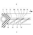
図1および図2は、本発明の第1実施例に係る密封装置を示している。当該実施例に係る密封装置は、機器(図示せず)の軸孔内周面に装着されるとともにシールリップ11を軸(図示せず)の周面に摺動可能に密接させることにより機内側Xの密封流体(図示せず)が大気側Yへ漏洩するのを抑制する。軸は矢印Z方向に回転する。当該密封装置はその機能または用途からして回転用オイルシールと称されることもある。 1 and 2 show a sealing device according to a first embodiment of the present invention. The sealing device according to this embodiment is mounted on the inner peripheral surface of a shaft hole of a device (not shown) and slidably comes into close contact with the peripheral surface of the shaft (not shown). X leakage fluid (not shown) is prevented from leaking to the atmosphere side Y. The shaft rotates in the direction of arrow Z. The sealing device is sometimes called a rotating oil seal because of its function or use.
シールリップ11は、そのリップ端12にて軸の周面に摺動可能に密接するものであって、リップ端12の機内側Xに機内側斜面13が設けられるとともにリップ端12の大気側Yに大気側斜面14が設けられている。また後者の大気側斜面14に、軸の回転時に密封流体に対するポンプ作用を発揮して密封流体を機内側Xへ押し戻すためのネジ15が円周上複数設けられている。
The
ネジ15は、スパイラル状に設けられた突起であって、リップ端12に達するように設けられた断面均一の平行ネジ16と、平行ネジ16から連続して設けられた舟底形ネジ17との組み合わせにより形成されている。ネジ15はそのリップ端側の基端部から大気側Yの先端部へかけて軸回転方向Zの後方へ向けて傾斜するように形成されている。平行ネジ16は例えば略三角断面形状の突起であって、その断面形状が全長に亙って均一な形状に形成されている。舟底形ネジ17は例えば略三角断面形状の突起であって、その高さおよび幅が長手方向の中央部で最も大きく、両端部へ向けて徐々に縮小される形状に形成されている。図1では作図の都合上、ネジ15が3つのみ描かれているが、ネジ15は全周に亙って多数が設けられている。
The
また、当該実施例に係る密封装置では、大気側Yの外部ダスト(図示せず)がリップ端12のほうへ侵入しないよう以下の構成が設けられている。ダストは例えば、泥水に含まれる砂粒などである。
Further, in the sealing device according to the embodiment, the following configuration is provided so that external dust (not shown) on the atmosphere side Y does not enter the
すなわち、上記シールリップ11の大気側斜面14上において、大気側Yの外部ダストが互いに隣り合うネジ15間の間隙部を介してリップ端12のほうへ侵入しないよう、互いに隣り合うネジ15間にダスト侵入防止用の立体形状21が設けられている。
That is, on the atmosphere-side
立体形状21は、リップ端12と平行な方向すなわち円周方向に延びる直線状の突起22よりなり、突起22は、その長手方向両端部22a,22bがそれぞれネジ15における平行ネジ16および舟底形ネジ17の接続部に連続している。
The three-
突起22の断面形状は特に限定されないが、当該実施例では図2に示すように略三角断面形状とされている。三角はその頂点22cが大気側Yに寄った不等辺三角形とされ、大気側の面22dの仰角θ1がリップ端側の面22eの仰角θ2より大きく設定されている(θ1>θ2)。また突起22の高さh1は、突起22が連結された平行ネジ16の高さh2より少々小さく設定されている(h1<h2)。突起22は、その奏する機能からして、堰と称することもできる。
The cross-sectional shape of the
上記構成の密封装置においては、大気側Yの外部ダストがリップ端12のほうへ侵入するのを抑制すべく互いに隣り合うネジ15間にダスト侵入防止用の立体形状21が設けられているため、この立体形状21が、大気側Yのダストがリップ端12のほうへ侵入するのを抑制する機能を発揮する。立体形状21はリップ端12と平行な方向に延びる突起22よりなり、突起22はダストを堰き止めるため、ダストがリップ端12のほうへ侵入するのが抑制される。突起22は長手方向両端部22a,22bがそれぞれネジ15に連続しているため、突起22とネジ15との間をダストが通過することはない。突起22は略三角断面形状とされるとともに大気側の面22dの仰角θ1が大きく設定されているため、ダストはこの大気側の面22dを乗り越えにくい。したがって以上のことから大気側Yのダストがリップ端12のほうへ侵入するのを抑制することができ、もってダストの噛み込みによる密封流体の漏れを抑制することができる。
In the sealing device configured as described above, the three-
また、突起22の高さh1が、対応する位置に設けられた平行ネジ16の高さh2より小さく設定されているため、突起22はネジ15によるポンプ作用を阻害しない。したがってダスト侵入防止用の突起22が設けられてもネジ15によるポンプ作用が十分に発揮される。
Further, since the height h 1 of the
上記第1実施例に係る密封装置は、その構成が以下のようなものであっても良い。 The sealing device according to the first embodiment may have the following configuration.
(イ)
上記第1実施例では、突起22を略三角断面形状としたが、これに代えて突起22を略四角断面形状とする。四角には長方形、正方形または台形などが含まれる。第2実施例として示す図3では、突起22が長方形の断面形状とされている。尚、三角、四角を問わず、その大気側の面22dは軸と直角(θ1<90°)ないし大気側斜面14と直角(θ1=90°)の角度範囲内に設定するのが、ダストを堰き止めやすいため、好適である。θ1は90°より大きくても良い(θ1>90°)。
(I)
In the first embodiment, the
(ロ)
上記第1実施例では、立体形状21を突起22としたが、これに代えて立体形状21を溝とする。第3実施例として示す図4では、立体形状21が、リップ端12と平行な方向すなわち円周方向に延びる直線状の溝23とされ、溝23はその長手方向両端部(図示せず)がそれぞれネジ15における平行ネジ16および舟底形ネジ17の接続部に連続している。溝23の断面形状は特に限定されないが、当該実施例では略三角断面形状とされている。三角はその底点23cがリップ端側に寄った不等辺三角形とされ、リップ端側の面23eの伏角θ3が大気側の面23dの伏角θ4より大きく設定されている(θ3>θ4)。溝23は略四角断面形状であっても良い。尚、三角、四角を問わず、そのリップ端側の面23eは軸と直角(θ3<90°)ないし大気側斜面14と直角(θ3=90°)の角度範囲内に設定するのが、ダストを堰き止めやすいため、好適である。θ3は90°より大きくても良い(θ3>90°)。
(B)
In the said 1st Example, although the
(ハ)
上記第1実施例では、立体形状21の突起22をネジ15間に1箇所ずつ設けたが、これに代えて立体形状21の突起または溝をネジ15間に複数個所に亙って設ける。
(C)
In the first embodiment, the
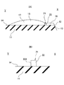
第4実施例として示す図5および図6において、立体形状21は、ネジ15における平行ネジ16および舟底形ネジ17の接続部に連続するように設けられた第1立体形状の突起24と、舟底形ネジ17に連続するように設けられた第2立体形状の突起25との組み合わせによって形成されている。第1立体形状の突起24は第2立体形状の突起25のリップ端側に配置され、第2立体形状の突起25は第1立体形状の突起24の大気側Yに配置され、両突起24,25は軸方向の間隔を開けて配置されている。第1立体形状の突起24はその長手方向両端部24a,24bがそれぞれ平行ネジ16および舟底形ネジ17の接続部に連続している。第2立体形状の突起25はその長手方向両端部25a,25bがそれぞれ舟底形ネジ17に連続している。突起24,25はいずれも略三角断面形状とされ、三角はその頂点24c,25cが大気側Yに寄った不等辺三角形とされ、大気側の面24d,25aの仰角θ1がリップ端側の面24e,25eの仰角θ2より大きく設定されている(θ1>θ2)。
In FIGS. 5 and 6 shown as the fourth embodiment, the three-
また、平行ネジ16の高さをh3、舟底形ネジ17の最大高さをh4、第1立体形状の突起24の高さをh5、第2立体形状の突起25の高さをh6として、
h5<h3≦h6<h4
の関係を充足するように設定されている。
Further, the height of the
h 5 <h 3 ≦ h 6 <h 4
It is set to satisfy the relationship.
そして、この第4実施例では、立体形状21の突起24,25がネジ15間に複数個所に亙って設けられているため、ダスト侵入に対する抑制効果が高いとともに、第1立体形状の突起24の高さh5が、対応する位置に設けられた平行ネジ16の高さh3より小さく設定され、第2立体形状の突起25の高さh6が、対応する位置に設けられた舟底形ネジ17の最大高さh4より小さく設定されているため、突起24,25はいずれもネジ15によるポンプ作用を阻害しない。したがってダスト侵入防止用の突起24,25が複数個所に亙って設けられてもネジ15によるポンプ作用が十分に発揮される。
And in this 4th Example, since the
11 シールリップ
12 リップ端
13 機内側斜面
14 大気側斜面
15 ネジ
16 平行ネジ
17 舟底形ネジ
21 立体形状
22,24,25 突起
22a,22b,23a,23b,24a,24b,25a,25b 長手方向端部
22c,24c,25c 頂点
22d,23d,24d,25d 大気側の面
22e,23e,24e,25e リップ端側の面
23 溝
23c 底点
X 機内側
Y 大気側
DESCRIPTION OF
Claims (3)
シールリップのリップ端にて軸に接触するとともに前記シールリップの大気側斜面に前記密封流体に対するポンプ作用を発揮するネジを円周上複数設けた密封装置において、
大気側の外部ダストが前記リップ端のほうへ侵入するのを抑制すべく前記ネジ間にダスト侵入防止用の立体形状を設け、
前記立体形状は、前記リップ端と平行な方向に延びる突起または溝よりなり、
前記突起または溝は、その長手方向両端部がそれぞれ前記ネジに連続しており、
前記突起は、その頂点が大気側に寄った略三角断面形状であり、
前記溝は、その底点がリップ端側に寄った略三角断面形状であることを特徴とする密封装置。 A sealing device that suppresses leakage of the sealing fluid inside the machine to the atmosphere side,
In the sealing device provided with a plurality of screws on the circumference that contact the shaft at the lip end of the seal lip and that exert a pumping action on the sealing fluid on the atmosphere-side slope of the seal lip,
In order to suppress external dust on the air side from entering the lip end, a three-dimensional shape for preventing dust intrusion is provided between the screws,
The three-dimensional shape is composed of protrusions or grooves extending in a direction parallel to the lip end,
The protrusions or grooves have both longitudinal ends continuous to the screws ,
The protrusion has a substantially triangular cross-sectional shape whose apex is close to the atmosphere side,
The sealing device according to claim 1, wherein the groove has a substantially triangular cross-sectional shape with a bottom point close to a lip end side .
シールリップのリップ端にて軸に接触するとともに前記シールリップの大気側斜面に前記密封流体に対するポンプ作用を発揮するネジを円周上複数設けた密封装置において、
大気側の外部ダストが前記リップ端のほうへ侵入するのを抑制すべく前記ネジ間にダスト侵入防止用の立体形状を設け、
前記立体形状は、前記リップ端と平行な方向に延びる突起または溝よりなり、
前記突起または溝は、その長手方向両端部がそれぞれ前記ネジに連続しており、
前記突起は、略三角または四角断面形状であり、前記突起の大気側の面は前記軸と直角ないし前記大気側斜面と直角の角度範囲に設定され、
前記溝は、略三角または四角断面形状であり、前記溝のリップ端側の面は前記軸と直角ないし前記大気側斜面と直角の角度範囲に設定されていることを特徴とする密封装置。 A sealing device that suppresses leakage of the sealing fluid inside the machine to the atmosphere side,
In the sealing device provided with a plurality of screws on the circumference that contact the shaft at the lip end of the seal lip and that exert a pumping action on the sealing fluid on the atmosphere-side slope of the seal lip,
In order to suppress external dust on the air side from entering the lip end, a three-dimensional shape for preventing dust intrusion is provided between the screws,
The three-dimensional shape is composed of protrusions or grooves extending in a direction parallel to the lip end,
The protrusions or grooves have both longitudinal ends continuous to the screws,
The protrusion has a substantially triangular or quadrangular cross-sectional shape, and the atmosphere side surface of the protrusion is set to an angle range that is perpendicular to the axis or perpendicular to the atmosphere side slope,
The groove has a substantially triangular or quadrangular cross-sectional shape, and a surface on the lip end side of the groove is set in an angle range perpendicular to the axis or perpendicular to the atmosphere-side inclined surface.
前記ネジはそれぞれ、前記リップ端近傍に設けられた断面均一の平行ネジと、前記平行ネジから連続して設けられた舟底形ネジとよりなり、
前記立体形状は、前記平行ネジおよび舟底形ネジの接続部または前記平行ネジに連続するよう設けられた第1立体形状の突起と、前記舟底形ネジに連続するように設けられた第2立体形状の突起とよりなり、
前記平行ネジの高さをh3、前記舟底形ネジの最大高さをh4、前記第1立体形状の突起の高さをh5、前記第2立体形状の突起の高さをh6として、
h5<h3≦h6<h4
の関係を充足することを特徴とする密封装置。 The sealing device according to claim 1 or 2 ,
Each of the screws consists of a parallel screw having a uniform cross section provided near the lip end and a boat bottom screw provided continuously from the parallel screw,
The three-dimensional shape includes a connecting portion of the parallel screw and the boat bottom screw or a first three-dimensional protrusion provided to be continuous with the parallel screw and a second screw provided to be continuous with the boat bottom screw. It consists of three-dimensional protrusions,
The height of the parallel screw is h 3 , the maximum height of the boat bottom screw is h 4 , the height of the first three-dimensional protrusion is h 5 , and the height of the second three-dimensional protrusion is h 6. As
h 5 <h 3 ≦ h 6 <h 4
The sealing device characterized by satisfying the relationship.
Priority Applications (8)
| Application Number | Priority Date | Filing Date | Title |
|---|---|---|---|
| JP2012102102A JP5637172B2 (en) | 2012-04-27 | 2012-04-27 | Sealing device |
| EP12875052.8A EP2843269B1 (en) | 2012-04-27 | 2012-12-11 | Sealing device |
| CN201280054465.4A CN104254720B (en) | 2012-04-27 | 2012-12-11 | Sealing device |
| US14/356,048 US9593776B2 (en) | 2012-04-27 | 2012-12-11 | Sealing device |
| PCT/JP2012/081998 WO2013161120A1 (en) | 2012-04-27 | 2012-12-11 | Sealing device |
| KR1020147012561A KR101955406B1 (en) | 2012-04-27 | 2012-12-11 | Sealing device |
| CN201610119066.1A CN105587864B (en) | 2012-04-27 | 2012-12-11 | Sealing device |
| US15/019,121 US9644743B2 (en) | 2012-04-27 | 2016-02-09 | Sealing device |
Applications Claiming Priority (1)
| Application Number | Priority Date | Filing Date | Title |
|---|---|---|---|
| JP2012102102A JP5637172B2 (en) | 2012-04-27 | 2012-04-27 | Sealing device |
Publications (3)
| Publication Number | Publication Date |
|---|---|
| JP2013228074A JP2013228074A (en) | 2013-11-07 |
| JP2013228074A5 JP2013228074A5 (en) | 2014-10-09 |
| JP5637172B2 true JP5637172B2 (en) | 2014-12-10 |
Family
ID=49482481
Family Applications (1)
| Application Number | Title | Priority Date | Filing Date |
|---|---|---|---|
| JP2012102102A Active JP5637172B2 (en) | 2012-04-27 | 2012-04-27 | Sealing device |
Country Status (6)
| Country | Link |
|---|---|
| US (2) | US9593776B2 (en) |
| EP (1) | EP2843269B1 (en) |
| JP (1) | JP5637172B2 (en) |
| KR (1) | KR101955406B1 (en) |
| CN (2) | CN105587864B (en) |
| WO (1) | WO2013161120A1 (en) |
Cited By (2)
| Publication number | Priority date | Publication date | Assignee | Title |
|---|---|---|---|---|
| US10641395B2 (en) | 2015-03-31 | 2020-05-05 | Nok Corporation | Sealing apparatus |
| US11287042B2 (en) | 2016-11-25 | 2022-03-29 | Nok Corporation | Sealing apparatus |
Families Citing this family (6)
| Publication number | Priority date | Publication date | Assignee | Title |
|---|---|---|---|---|
| JP5637172B2 (en) * | 2012-04-27 | 2014-12-10 | Nok株式会社 | Sealing device |
| JP6536797B2 (en) * | 2015-04-03 | 2019-07-03 | Nok株式会社 | Sealing device |
| JP6809847B2 (en) * | 2016-09-01 | 2021-01-06 | Nok株式会社 | Sealing device |
| JP7123658B2 (en) * | 2018-06-25 | 2022-08-23 | Nok株式会社 | sealing device |
| WO2020045070A1 (en) * | 2018-08-28 | 2020-03-05 | Nok株式会社 | Sealing device |
| US20240026977A1 (en) * | 2020-09-15 | 2024-01-25 | Nok Corporation | Sealing device |
Family Cites Families (38)
| Publication number | Priority date | Publication date | Assignee | Title |
|---|---|---|---|---|
| CH410558A (en) * | 1965-02-22 | 1966-03-31 | Micus Immobiliar Und Finanzier | Elastic sealing gasket for rotating shafts |
| US3534969A (en) | 1966-09-27 | 1970-10-20 | Gen Motors Corp | Seal |
| US3801113A (en) * | 1971-11-18 | 1974-04-02 | Parker Hannifin Corp | Rotary shaft seal |
| ZA732297B (en) * | 1972-04-10 | 1974-01-30 | Repco Res Proprietary Ltd | Improved fluid seal |
| US4174845A (en) * | 1974-08-15 | 1979-11-20 | Repco Research Proprietary Limited | Fluid seal |
| US4118856A (en) * | 1974-12-02 | 1978-10-10 | Garlock Inc | Bi-directional hydrodynamic shaft seal method |
| JPS5547050A (en) * | 1978-09-29 | 1980-04-02 | Arai Pump Mfg Co Ltd | Cylindrical surface seal |
| US4288083A (en) * | 1980-02-07 | 1981-09-08 | International Packings Corporation | Hydrodynamic shaft seal |
| US4300777A (en) * | 1980-06-16 | 1981-11-17 | General Motors Corporation | Fluid seal |
| JP2582922B2 (en) | 1990-03-27 | 1997-02-19 | シャープ株式会社 | Recording and playback device |
| JPH07208611A (en) | 1994-01-26 | 1995-08-11 | Koyo Seiko Co Ltd | Oil seal |
| JP3278349B2 (en) | 1995-05-25 | 2002-04-30 | エヌオーケー株式会社 | Sealing device |
| US5759466A (en) * | 1995-05-25 | 1998-06-02 | Nok Corporation | Method of making lip-type oil seals having improved sealing edge |
| JPH0972426A (en) * | 1995-09-07 | 1997-03-18 | Nok Corp | Sealing device |
| JP3860283B2 (en) * | 1996-06-26 | 2006-12-20 | Nok株式会社 | Sealing device |
| EP0939257A3 (en) * | 1998-02-27 | 2000-05-31 | NOK Corporation | Oil seal |
| JPH11270697A (en) * | 1998-03-23 | 1999-10-05 | Nok Corp | Oil seal |
| US6494462B2 (en) * | 1998-05-06 | 2002-12-17 | Kalsi Engineering, Inc. | Rotary seal with improved dynamic interface |
| JP4244442B2 (en) | 1998-06-12 | 2009-03-25 | Nok株式会社 | Sealing device |
| JP2000081149A (en) * | 1998-09-07 | 2000-03-21 | Nok Corp | Seal device |
| JP2001027326A (en) * | 1999-07-14 | 2001-01-30 | Keeper Co Ltd | Oil seal |
| JP2001173798A (en) | 1999-12-20 | 2001-06-26 | Arai Pump Mfg Co Ltd | Oil seal with screw |
| JP2001295942A (en) * | 2000-04-14 | 2001-10-26 | Keeper Co Ltd | Threaded oil seal |
| JP2001317635A (en) * | 2000-05-02 | 2001-11-16 | Toyota Industries Corp | Lip type seal |
| US6729624B1 (en) * | 2001-02-20 | 2004-05-04 | Freudenberg-Nok General Partnership | Radial shaft seal |
| JP4366897B2 (en) * | 2002-02-28 | 2009-11-18 | Nok株式会社 | Mold processing method |
| JP4244585B2 (en) * | 2002-08-05 | 2009-03-25 | Nok株式会社 | Sealing device |
| JP2005172061A (en) * | 2003-12-09 | 2005-06-30 | Nok Corp | Sealing device |
| KR101239771B1 (en) * | 2005-06-21 | 2013-03-06 | 엔오케이 가부시키가이샤 | Oil seal and process for producing the same |
| TWI275723B (en) * | 2005-12-29 | 2007-03-11 | Nak Sealing Technologies Corp | Sealing component |
| JP5168514B2 (en) * | 2007-04-11 | 2013-03-21 | Nok株式会社 | Oil seal |
| DE602007005783D1 (en) | 2007-05-09 | 2010-05-20 | Freudenberg Carl Kg | sealing ring |
| WO2009031199A1 (en) * | 2007-09-04 | 2009-03-12 | Arai Seisakusho Co., Ltd. | Hermetic sealing device |
| JP2009074602A (en) * | 2007-09-20 | 2009-04-09 | Nok Corp | Oil seal |
| JP2009074644A (en) | 2007-09-21 | 2009-04-09 | Nok Corp | Oil seal |
| JP2009185968A (en) * | 2008-02-08 | 2009-08-20 | Nok Corp | Oil seal |
| JP5637172B2 (en) * | 2012-04-27 | 2014-12-10 | Nok株式会社 | Sealing device |
| DE102013207029B4 (en) * | 2013-04-18 | 2016-05-04 | Aktiebolaget Skf | Radial shaft seal arrangement |
-
2012
- 2012-04-27 JP JP2012102102A patent/JP5637172B2/en active Active
- 2012-12-11 KR KR1020147012561A patent/KR101955406B1/en active IP Right Grant
- 2012-12-11 EP EP12875052.8A patent/EP2843269B1/en active Active
- 2012-12-11 WO PCT/JP2012/081998 patent/WO2013161120A1/en active Application Filing
- 2012-12-11 CN CN201610119066.1A patent/CN105587864B/en active Active
- 2012-12-11 CN CN201280054465.4A patent/CN104254720B/en active Active
- 2012-12-11 US US14/356,048 patent/US9593776B2/en active Active
-
2016
- 2016-02-09 US US15/019,121 patent/US9644743B2/en active Active
Cited By (2)
| Publication number | Priority date | Publication date | Assignee | Title |
|---|---|---|---|---|
| US10641395B2 (en) | 2015-03-31 | 2020-05-05 | Nok Corporation | Sealing apparatus |
| US11287042B2 (en) | 2016-11-25 | 2022-03-29 | Nok Corporation | Sealing apparatus |
Also Published As
| Publication number | Publication date |
|---|---|
| KR20150003146A (en) | 2015-01-08 |
| CN104254720A (en) | 2014-12-31 |
| JP2013228074A (en) | 2013-11-07 |
| EP2843269A1 (en) | 2015-03-04 |
| CN104254720B (en) | 2016-08-17 |
| KR101955406B1 (en) | 2019-03-07 |
| CN105587864B (en) | 2019-07-05 |
| CN105587864A (en) | 2016-05-18 |
| US9644743B2 (en) | 2017-05-09 |
| EP2843269A4 (en) | 2015-08-05 |
| WO2013161120A1 (en) | 2013-10-31 |
| US20160161002A1 (en) | 2016-06-09 |
| US9593776B2 (en) | 2017-03-14 |
| EP2843269B1 (en) | 2019-02-20 |
| US20140319775A1 (en) | 2014-10-30 |
Similar Documents
| Publication | Publication Date | Title |
|---|---|---|
| JP5637172B2 (en) | Sealing device | |
| JP6445085B2 (en) | Sealing device | |
| JP6033996B1 (en) | Sealing device | |
| US20150276059A1 (en) | Oil seal | |
| CA2864705C (en) | Sealing device | |
| JP2013228074A5 (en) | ||
| JP2008281013A (en) | Sealing device | |
| JP5800141B2 (en) | Sealing device | |
| JP2023017975A (en) | sealing device | |
| JP6204987B2 (en) | Sealing device | |
| JP6961094B2 (en) | Sealing device | |
| JP5904328B2 (en) | Sealing device | |
| JP5980592B2 (en) | Sealing device | |
| JP5904327B2 (en) | Sealing device | |
| JP6809847B2 (en) | Sealing device | |
| JP5212601B2 (en) | Sealing device | |
| JP2011179618A (en) | Gasket and sealing structure | |
| JP2019173773A (en) | Sealing device | |
| JP6231352B2 (en) | Oil seal |
Legal Events
| Date | Code | Title | Description |
|---|---|---|---|
| A521 | Request for written amendment filed |
Free format text: JAPANESE INTERMEDIATE CODE: A523 Effective date: 20140821 |
|
| A621 | Written request for application examination |
Free format text: JAPANESE INTERMEDIATE CODE: A621 Effective date: 20140821 |
|
| A871 | Explanation of circumstances concerning accelerated examination |
Free format text: JAPANESE INTERMEDIATE CODE: A871 Effective date: 20140821 |
|
| TRDD | Decision of grant or rejection written | ||
| A975 | Report on accelerated examination |
Free format text: JAPANESE INTERMEDIATE CODE: A971005 Effective date: 20140918 |
|
| A01 | Written decision to grant a patent or to grant a registration (utility model) |
Free format text: JAPANESE INTERMEDIATE CODE: A01 Effective date: 20140924 |
|
| A61 | First payment of annual fees (during grant procedure) |
Free format text: JAPANESE INTERMEDIATE CODE: A61 Effective date: 20141007 |
|
| R150 | Certificate of patent or registration of utility model |
Ref document number: 5637172 Country of ref document: JP Free format text: JAPANESE INTERMEDIATE CODE: R150 |
|
| R250 | Receipt of annual fees |
Free format text: JAPANESE INTERMEDIATE CODE: R250 |
|
| R250 | Receipt of annual fees |
Free format text: JAPANESE INTERMEDIATE CODE: R250 |
|
| R250 | Receipt of annual fees |
Free format text: JAPANESE INTERMEDIATE CODE: R250 |
|
| R250 | Receipt of annual fees |
Free format text: JAPANESE INTERMEDIATE CODE: R250 |