JP2005143151A - Annular power module - Google Patents

Annular power module Download PDF

Info

Publication number
JP2005143151A
JP2005143151A JP2003372217A JP2003372217A JP2005143151A JP 2005143151 A JP2005143151 A JP 2005143151A JP 2003372217 A JP2003372217 A JP 2003372217A JP 2003372217 A JP2003372217 A JP 2003372217A JP 2005143151 A JP2005143151 A JP 2005143151A
Authority
JP
Japan
Prior art keywords
annular
power module
motor
power
conductor
Prior art date
Legal status (The legal status is an assumption and is not a legal conclusion. Google has not performed a legal analysis and makes no representation as to the accuracy of the status listed.)
Pending
Application number
JP2003372217A
Other languages
Japanese (ja)
Inventor
Yasuhiko Nishi
康彦 西
Nobuyuki Hirano
信行 平野
Akira Fukuda
晃 福田
Takashi Hoshino
孝志 星野
Current Assignee (The listed assignees may be inaccurate. Google has not performed a legal analysis and makes no representation or warranty as to the accuracy of the list.)
Sumitomo Electric Industries Ltd
Original Assignee
Sumitomo Electric Industries Ltd
Priority date (The priority date is an assumption and is not a legal conclusion. Google has not performed a legal analysis and makes no representation as to the accuracy of the date listed.)
Filing date
Publication date
Application filed by Sumitomo Electric Industries Ltd filed Critical Sumitomo Electric Industries Ltd
Priority to JP2003372217A priority Critical patent/JP2005143151A/en
Publication of JP2005143151A publication Critical patent/JP2005143151A/en
Pending legal-status Critical Current

Links

Images

Landscapes

  • Inverter Devices (AREA)

Abstract

<P>PROBLEM TO BE SOLVED: To improve the space efficiency of the portion in which a power module and a motor are installed and to enable easy change in the number of phases of the motor. <P>SOLUTION: In an annular power module, a first annular conductor 21 of a power source side and a second annular conductor 22 of an installation side are, for example, disposed on a concentric circle, power element parts 23a-23f having a high arm side switching element of an inverter and a low side switching element are connected between the first annular conductor 21 and the second annular conductor 22, and the connecting points of both the switching elements 31, 32 are connected by a metal member, etc., directly to the connecting terminals 9 of the motor coils 12a-12f in every phase. Wiring between the motor and the inverter can be omitted, and these cooling devices can be shared. <P>COPYRIGHT: (C)2005,JPO&NCIPI

Description

本発明は、モータを駆動するためのパワー素子部を備える環状パワーモジュールに関するものである。   The present invention relates to an annular power module including a power element unit for driving a motor.

従来、例えばハイブリッドカーのエンジンモータを駆動するために、パワーモジュールとして図21のようなインバータ装置1が使用されていた。このインバータ装置1は、車両走行用の三相交流電動機であるモータ2を駆動する三相インバータであって、モータ2のU相、V相及びW相の各相におけるそれぞれのハイアーム側スイッチング素子3a,3b,3cとして例えばSiC、GaN、Cなどの高温動作可能なワイドバンドギャップデバイスやNチャネルのパワーMOSFET等を有し、また各相におけるそれぞれのローアーム側スイッチング素子4a,4b,4cとして例えばSiC、GaN、Cなどの高温動作可能なワイドバンドギャップデバイスやNチャネルのパワーMOSFET等を有する。   Conventionally, for example, an inverter device 1 as shown in FIG. 21 has been used as a power module to drive an engine motor of a hybrid car. This inverter device 1 is a three-phase inverter that drives a motor 2 that is a three-phase AC motor for vehicle travel, and each high-arm side switching element 3a in each of the U-phase, V-phase, and W-phase of the motor 2. , 3b, 3c include wide band gap devices capable of operating at high temperatures such as SiC, GaN, and C, N-channel power MOSFETs, etc., and low arm side switching elements 4a, 4b, and 4c in each phase include, for example, SiC , GaN, C, and other wide bandgap devices capable of operating at high temperatures, N-channel power MOSFETs, and the like.

ハイアーム側スイッチング素子3a,3b,3cのドレインはプラス(+)側電源Pに共に接続され、同じくその各ソースはそれぞれ同相のローアーム側スイッチング素子4a,4b,4cの各ドレインに接続されている。また、ローアーム側スイッチング素子4a,4b,4cのソースは共にマイナス(−)側Nに接続されている。さらに、各スイッチング素子3a,3b,3c,4a,4b,4cに対して、これらが電流を流す方向とは反対側に電流を流すフリーホイールダイオード5a,5b,5c,6a,6b,6cがそれぞれ並列に接続されている。そして、ハイアーム側スイッチング素子3a,3b,3cの各ソースとローアーム側スイッチング素子4a,4b,4cの各ドレインとの接続点の電圧が、モータ2のU相、V相及びW相の各相に接続される。   The drains of the high arm side switching elements 3a, 3b, 3c are connected together to the plus (+) side power supply P, and their sources are connected to the drains of the in-phase low arm side switching elements 4a, 4b, 4c, respectively. The sources of the low arm side switching elements 4a, 4b, and 4c are all connected to the negative (−) side N. Furthermore, each of the switching elements 3a, 3b, 3c, 4a, 4b, and 4c has free wheel diodes 5a, 5b, 5c, 6a, 6b, and 6c that flow current in the direction opposite to the direction in which the current flows. Connected in parallel. The voltage at the connection point between the sources of the high arm side switching elements 3a, 3b, 3c and the drains of the low arm side switching elements 4a, 4b, 4c becomes the U phase, V phase, and W phase of the motor 2, respectively. Connected.

ここで、図21中の符号7a,7b,7c,8a,8b,8cは、各スイッチング素子3a,3b,3c,4a,4b,4cの制御入力端子であるゲート端子を示しており、所定の制御部からゲート端子7a,7b,7c,8a,8b,8cに与えられる制御信号に応じたタイミングで、各スイッチング素子3a,3b,3c,4a,4b,4cがオンオフする。   Here, reference numerals 7a, 7b, 7c, 8a, 8b, and 8c in FIG. 21 indicate gate terminals that are control input terminals of the respective switching elements 3a, 3b, 3c, 4a, 4b, and 4c. Each switching element 3a, 3b, 3c, 4a, 4b, 4c is turned on / off at a timing according to a control signal given from the control unit to the gate terminals 7a, 7b, 7c, 8a, 8b, 8c.

尚、各スイッチング素子3a,3b,3c,4a,4b,4cとしては、一般的なインバータで使用されているものであれば図21のようなパワーMOSFETに限られず、パワー接合トランジスタまたはIGBTなどの他のスイッチング素子が使用されることもある。   Each switching element 3a, 3b, 3c, 4a, 4b, 4c is not limited to the power MOSFET as shown in FIG. 21 as long as it is used in a general inverter, but is not limited to a power junction transistor or IGBT. Other switching elements may be used.

ここで、従来においては、図22の如く、インバータ装置1とモータ2とを互いに別個独立したユニットとして個別に構成し、インバータ装置1の各相の出力端子9a,9b,9cとモータ2との間にパワーケーブル10a,10b,10cを配線していた。   Here, conventionally, as shown in FIG. 22, the inverter device 1 and the motor 2 are individually configured as separate and independent units, and the output terminals 9 a, 9 b, 9 c of each phase of the inverter device 1 are connected to the motor 2. Power cables 10a, 10b, and 10c were wired between them.

また、一般にインバータ装置1とモータ2は双方とも発熱するため、それぞれに冷却装置(図示省略)を設置していた。   In general, since both the inverter device 1 and the motor 2 generate heat, a cooling device (not shown) is provided for each.

従来では、上述のように、図22の如く、パワーモジュールとしてのインバータ装置1とモータ2とを互いに別個独立したユニットとして個別に構成していたため、インバータ装置1の各相の出力端子9a,9b,9cとモータ2との間にパワーケーブル10a,10b,10cを配線する必要があった。このため、大きな配線スペースを必要とした。   Conventionally, as described above, as shown in FIG. 22, the inverter device 1 and the motor 2 as the power modules are individually configured as separate and independent units, and therefore, the output terminals 9 a and 9 b of the respective phases of the inverter device 1. , 9c and the motor 2 need to be wired with power cables 10a, 10b, 10c. For this reason, a large wiring space is required.

また、従来では、パワーモジュールとしてのインバータ装置1とモータ2のそれぞれに冷却装置を設置する必要があったため、スペース効率が悪かった。例えば、水または油等の冷媒を配管を通じて供給する場合は、その配管の設置スペースが必要であり、また配策レイアウトも煩雑となっていた。   Conventionally, since it is necessary to install a cooling device in each of the inverter device 1 and the motor 2 as power modules, the space efficiency is poor. For example, when a coolant such as water or oil is supplied through a pipe, an installation space for the pipe is required, and the layout of the arrangement is complicated.

あるいは、空冷によりインバータ装置(パワーモジュール)1及びモータ2を冷却する場合、空冷スペースが多大に必要となっていた。   Alternatively, when the inverter device (power module) 1 and the motor 2 are cooled by air cooling, a large air cooling space is required.

さらにまた、従来においては、通常、U相、V相及びW相の3相の制御をインバータ装置1で行っていたが、相数を増加するなどの回路設計上の変更を行う場合には、その分パワーケーブル10a,10b,10cを新たに配線しなければならず、不便であった。   Furthermore, conventionally, control of three phases of U phase, V phase, and W phase is usually performed by the inverter device 1, but when making a change in circuit design such as increasing the number of phases, Accordingly, the power cables 10a, 10b, and 10c have to be newly wired, which is inconvenient.

そこで、本発明の課題は、パワーモジュール及びモータが設置される部位のスペース効率を向上するとともに、モータの相数を容易に変更し得る環状パワーモジュールを提供することにある。   Therefore, an object of the present invention is to provide an annular power module that can improve the space efficiency of a portion where the power module and the motor are installed and can easily change the number of phases of the motor.

上記課題を解決すべく、請求項1に記載の発明は、モータを駆動するためのパワー素子部を備える環状パワーモジュールであって、前記モータの外周に沿って環状に形成された環状導体と、前記モータ内のモータコイルと同数、その数を整数で割った数または整数倍の数に設けられ、前記環状導体に接続され、前記モータコイルに近傍する位置に配置されて当該モータコイルにそれぞれ接続される前記パワー素子部とを備えるものである。   In order to solve the above problem, the invention according to claim 1 is an annular power module including a power element unit for driving a motor, and an annular conductor formed in an annular shape along the outer periphery of the motor; The same number as the motor coils in the motor, the number obtained by dividing the number by an integer or a multiple of the integer, connected to the annular conductor, arranged at a position near the motor coil and connected to the motor coil, respectively The power element unit is provided.

請求項2に記載の発明は、前記環状導体が、前記モータの外周に沿って環状に形成されて第1の電位に設定される第1環状導体と、前記第1環状導体に非接続とされ、且つ前記モータの外周に沿って環状に形成されて第2の電位に設定される第2環状導体とを含み、前記各パワー素子部が、前記第1環状導体と前記第2環状導体との間に接続されるものである。   According to a second aspect of the present invention, the annular conductor is annularly formed along the outer periphery of the motor and is set to a first potential, and is disconnected from the first annular conductor. And a second annular conductor that is annularly formed along the outer periphery of the motor and is set to a second potential, and each power element portion includes a first annular conductor and a second annular conductor. It is connected between them.

請求項3に記載の発明は、請求項2に記載の環状パワーモジュールであって、前記各パワー素子部が、前記第1環状導体と前記前記モータ内のモータコイルとの接続と遮断とを切り替える第1のスイッチング素子と、前記第2環状導体と前記前記モータ内のモータコイルとの接続と遮断とを切り替える第2のスイッチング素子とをそれぞれ備えるものである。   Invention of Claim 3 is an annular power module of Claim 2, Comprising: Each said power element part switches connection and interruption | blocking with the said 1st annular conductor and the motor coil in the said motor A first switching element and a second switching element for switching between connection and disconnection between the second annular conductor and the motor coil in the motor are provided.

請求項4に記載の発明は、請求項1から請求項3のいずれかに記載の環状パワーモジュールであって、前記モータの外装の内部に組み込まれるものである。   A fourth aspect of the present invention is the annular power module according to any one of the first to third aspects, wherein the annular power module is incorporated in the exterior of the motor.

請求項5に記載の発明は、請求項2または請求項3に記載の環状パワーモジュールであって、前記モータがバスリング型モータであって、前記第1環状導体及び前記第2環状導体の少なくとも一方が、前記モータのバスリングである。   Invention of Claim 5 is the cyclic | annular power module of Claim 2 or Claim 3, Comprising: The said motor is a bus ring type motor, Comprising: At least of the said 1st annular conductor and the said 2nd annular conductor One is the bus ring of the motor.

請求項6に記載の発明は、請求項2、請求項3または請求項5に記載の環状パワーモジュールであって、前記第1環状導体と前記第2環状導体との間で、前記パワー素子部が設置された領域以外の部分に接続された他の電気部品をさらに備えるものである。   A sixth aspect of the present invention is the annular power module according to the second, third, or fifth aspect, wherein the power element portion is disposed between the first annular conductor and the second annular conductor. It further includes another electrical component connected to a part other than the region where the is installed.

請求項7に記載の発明は、請求項2に記載の環状パワーモジュールであって、前記第2の電位が接地電位であり、前記第2環状導体が、最も外周に配置されるものである。   A seventh aspect of the present invention is the annular power module according to the second aspect, wherein the second potential is a ground potential, and the second annular conductor is arranged on the outermost periphery.

請求項8に記載の発明は、請求項1から請求項7のいずれかに記載の環状パワーモジュールであって、前記モータに対する各相毎に、複数の前記パワー素子部が並列に設けられ、各相における複数の前記パワー素子部が、前記環状導体の環形状に沿って均等距離に離間配置されたものである。   Invention of Claim 8 is the cyclic | annular power module in any one of Claim 1-7, Comprising: The said several power element part is provided in parallel for every phase with respect to the said motor, The plurality of power element portions in the phase are spaced apart at an equal distance along the ring shape of the annular conductor.

請求項9に記載の発明は、請求項1から請求項8のいずれかに記載の環状パワーモジュールであって、前記パワー素子部の各相同士の離間距離が、前記環状導体の環形状に沿って均等に設定されたものである。   The invention according to claim 9 is the annular power module according to any one of claims 1 to 8, wherein a separation distance between the phases of the power element portion is along the annular shape of the annular conductor. Are set evenly.

請求項10に記載の発明は、請求項1から請求項7のいずれかに記載の環状パワーモジュールであって、前記モータに対する各相毎に、複数の前記パワー素子部が並列に設けられ、各相における複数の前記パワー素子部が、前記環状導体の環形状に沿って均等距離に離間配置され、且つ、前記パワー素子部の各相同士の離間距離が、各相における複数の前記パワー素子部同士の離間距離に等しい距離で、前記環状導体の環形状に沿って均等に設定されたものである。   Invention of Claim 10 is the cyclic | annular power module in any one of Claim 1-7, Comprising: The said several power element part is provided in parallel for every each phase with respect to the said motor, The plurality of power element portions in the phase are spaced apart at equal distances along the ring shape of the annular conductor, and the distance between the phases of the power element portion is the plurality of power element portions in each phase The distance is equal to the distance between them and is set evenly along the ring shape of the annular conductor.

請求項11に記載の発明は、請求項1から請求項10のいずれかに記載の環状パワーモジュールであって、前記環状導体及び前記パワー素子部を保持するとともに、内部に冷媒流路が形成された保持体をさらに備えるものである。   The invention according to claim 11 is the annular power module according to any one of claims 1 to 10, wherein the annular conductor and the power element portion are held, and a coolant channel is formed therein. The holding body is further provided.

請求項12に記載の発明は、請求項1から請求項11のいずれかに記載の環状パワーモジュールであって、前記環状導体の内部に、冷媒流路が形成されたものである。   A twelfth aspect of the present invention is the annular power module according to any one of the first to eleventh aspects, wherein a refrigerant flow path is formed inside the annular conductor.

尚、本明細書及び特許請求の範囲において、「均等」及び「等しい」という用語は、必ずしも厳密に「完全な均等」を意味するだけでなく、ある程度のばらつきを許容しつつ大まかな意味で均等であり、または等しければよい。この場合に許容されるばらつきは、製造上の寸法誤差によるばらつきと、設計上の意図的な寸法上のばらつきとの両方が含まれる。したがって、本明細書及び特許請求の範囲において、「均等距離」及び「等しい距離」という用語も、厳密に均等な寸法で設定された距離を意味するだけでなく、ある程度の寸法上のばらつきを許容しつつ大まかな意味で均等に設定された距離をも含むものである。   In the specification and claims, the terms “equal” and “equal” do not necessarily mean “perfectly equal” strictly, but are equivalent in a broad sense while allowing some variation. Or equal. Variations allowed in this case include both variations due to manufacturing dimensional errors and intentional dimensional variations in design. Therefore, in this specification and claims, the terms “equal distance” and “equal distance” not only mean distances set with strictly equal dimensions, but also allow for some dimensional variation. However, it includes distances that are set evenly in a rough sense.

請求項1及び請求項2に記載の発明の環状パワーモジュールは、環状導体(請求項2では第1環状導体及び第2環状導体)にパワー素子部を接続して環状に形成し、このパワー素子部をモータ内の各モータコイルに近傍する位置で当該各モータコイルにそれぞれ接続しているので、パワー素子部からモータコイルまでを接続するためのパワーケーブルを省略でき、配線省略によってスペース効率を大幅に向上することができる。   The annular power module according to the first and second aspects of the present invention is formed by connecting a power element portion to an annular conductor (the first annular conductor and the second annular conductor in claim 2) to form an annular shape. Since each part is connected to each motor coil at a position near each motor coil in the motor, the power cable for connecting from the power element part to the motor coil can be omitted. Can be improved.

また、モータとパワー素子部を近接配置しているので、モータに対する冷却装置と環状パワーモジュールに対する冷却装置とを共用することができる。例えば、水または油等の冷媒を配管を通して冷却する場合の配管の設置スペースが少なくて済み、あるいは、空冷する場合は空冷スペースが少なくて済む。したがって、冷却装置についてのスペース効率をも向上することができる。   Moreover, since the motor and the power element unit are arranged close to each other, the cooling device for the motor and the cooling device for the annular power module can be shared. For example, the installation space for piping when cooling a coolant such as water or oil through the piping is small, or the air cooling space is small when cooling with air. Therefore, the space efficiency for the cooling device can also be improved.

さらに、環状導体(請求項2では第1環状導体及び第2環状導体)が環状に形成されるので、パワー素子部の冷却部材として空気接触面積を大きくとることができ便利である。   Furthermore, since the annular conductors (the first annular conductor and the second annular conductor in claim 2) are formed in an annular shape, the air contact area can be increased as a cooling member for the power element portion, which is convenient.

さらにまた、環状パワーモジュール内で環状導体の任意の位置にパワー素子部を設置することが可能であるので、モータコイルの個数変更(モータの相数の変更)等の回路設計上の変更を行う場合に、製造工程においてその設計変更に容易に対応できるだけでなく、従来のようにパワーケーブルを新たに配線する必要がないため、便利である。   Furthermore, since it is possible to install the power element portion at any position of the annular conductor in the annular power module, changes in circuit design such as changing the number of motor coils (changing the number of motor phases) are performed. In this case, not only can the design change be easily dealt with in the manufacturing process, but there is no need to newly wire the power cable as in the conventional case, which is convenient.

また、請求項2に記載の発明の環状パワーモジュールは、環状導体が、モータの外周に沿って環状に形成されて第1の電位に設定される第1環状導体と、第1環状導体に非接続とされ、且つモータの外周に沿って環状に形成されて第2の電位に設定される第2環状導体とを含んでいるため、両環状導体の間の間隙や、モータと環状導体との間の間隙を空冷スペースとして利用できる利点がある。   According to a second aspect of the present invention, in the annular power module, the annular conductor is annularly formed along the outer periphery of the motor and is set to the first potential, and the first annular conductor is not And a second annular conductor that is annularly formed along the outer periphery of the motor and is set to the second potential, so that there is a gap between the two annular conductors and between the motor and the annular conductor. There is an advantage that the gap between them can be used as an air cooling space.

請求項3に記載の発明の環状パワーモジュールは、各パワー素子部が、第1環状導体とモータ内のモータコイルとの接続と遮断とを切り替える第1のスイッチング素子と、第2環状導体とモータ内のモータコイルとの接続と遮断とを切り替える第2のスイッチング素子とをそれぞれ備えるよう構成されるので、この環状パワーモジュールをインバータ装置として利用することが可能である。この場合、インバータ装置とモータとの配線を省略でききることによるスペース効率の向上を図ることができ、またインバータ装置の発熱とモータの発熱とを単一の冷却装置で冷却できる。   According to a third aspect of the present invention, there is provided the annular power module, wherein each power element section includes a first switching element that switches between connection and disconnection between the first annular conductor and a motor coil in the motor, a second annular conductor, and a motor. Since it is comprised so that it may each be provided with the 2nd switching element which switches connection and interruption | blocking with an inner motor coil, it is possible to utilize this cyclic | annular power module as an inverter apparatus. In this case, the space efficiency can be improved by eliminating the wiring between the inverter device and the motor, and the heat generation of the inverter device and the heat generation of the motor can be cooled by a single cooling device.

請求項4に記載の発明では、環状パワーモジュールがモータの外装の内部に組み込まれるので、スペース効率が向上するだけでなく、環状パワーモジュール一体型のモータとして取り扱いが便利である。特に、請求項3のように環状パワーモジュールがインバータ装置である場合に有効である。   In the invention according to claim 4, since the annular power module is incorporated in the exterior of the motor, not only the space efficiency is improved, but also the handling as a motor integrated with the annular power module is convenient. This is particularly effective when the annular power module is an inverter device as in claim 3.

請求項5に記載の発明の環状パワーモジュールは、モータがバスリング型モータであって、第1環状導体及び第2環状導体の少なくとも一方を、モータのバスリングで兼用しているので、部品コストが低減するとともに、スペース効率をさらに向上することができる。   In the annular power module according to the fifth aspect of the present invention, the motor is a bus ring type motor, and at least one of the first annular conductor and the second annular conductor is shared by the bus ring of the motor. And the space efficiency can be further improved.

請求項6に記載の発明の環状パワーモジュールは、第1の電位と第2の電位との間に接続される他の電気部品がある場合に、第1環状導体と第2環状導体との間の領域であって、パワー素子部を接地した以外の余ったスペースに他の電気部品を接地することができるので、さらにスペース効率を向上することができる。特に、請求項3のように環状パワーモジュールがインバータ装置である場合に、直流電源側であるP(+)端子とローアーム側スイッチング素子の接地側であるN端子との間にダイオードやコンデンサ等の他の電気部品が接続されるのが通常であるため、この電気部品を、外付けではなく第1環状導体と第2環状導体との間の余った領域に容易に接続することができ便利である。   According to a sixth aspect of the present invention, there is provided the annular power module between the first annular conductor and the second annular conductor when there is another electrical component connected between the first potential and the second potential. In this region, other electrical components can be grounded in a surplus space other than the grounding of the power element portion, so that the space efficiency can be further improved. In particular, when the annular power module is an inverter device as in claim 3, a diode, a capacitor, or the like is provided between the P (+) terminal on the DC power supply side and the N terminal on the ground side of the low arm side switching element. Since other electrical components are usually connected, this electrical component can be easily connected to the extra area between the first annular conductor and the second annular conductor instead of being externally attached. is there.

請求項7に記載の発明の環状パワーモジュールは、第2の電位が接地電位であり、第2環状導体が最も外周に配置されるので、この第2環状導体を自動車のボディ等の接地部位に容易に接続でき、マイナス(−)側Nを接地と共用することにより配線効率が向上する。   In the annular power module according to the seventh aspect of the invention, the second potential is the ground potential, and the second annular conductor is arranged on the outermost periphery. Wiring efficiency is improved by easily connecting and sharing the negative (−) side N with the ground.

請求項8に記載の発明の環状パワーモジュールは、各相において同時に動作するパワー素子部同士が均等な間隔で互いに離間しているので、発熱分布を分散させることができる。したがって、各相において同時に動作するパワー素子部同士を不均等な間隔で離間させる場合に比べて、放熱効率を向上できる。   In the annular power module according to the eighth aspect of the present invention, the power element portions operating simultaneously in each phase are separated from each other at equal intervals, so that the heat generation distribution can be dispersed. Therefore, the heat radiation efficiency can be improved as compared with the case where the power element units operating simultaneously in each phase are separated from each other at unequal intervals.

請求項9に記載の発明の環状パワーモジュールは、各相同士の離間間隔を均等にしているので、発熱分布を分散させることができる。したがって、各相同士の間隔を不均等に設定する場合に比べて、放熱効率を向上できる。   In the annular power module according to the ninth aspect of the invention, the spacing between the phases is made uniform, so that the heat generation distribution can be dispersed. Therefore, compared with the case where the space | interval of each phase is set unevenly, heat dissipation efficiency can be improved.

請求項10に記載の発明の環状パワーモジュールは、全てのパワー素子部を環状パワーモジュールの全体に亘って均等な離間間隔で配置することができ、発熱分布を均等に分散させることができる。したがって、放熱効率を大幅に向上できる。   In the annular power module according to the tenth aspect, all the power element portions can be arranged at equal intervals across the entire annular power module, and the heat generation distribution can be evenly distributed. Therefore, the heat dissipation efficiency can be greatly improved.

請求項11に記載の発明の環状パワーモジュールは、保持体内に冷媒流路を形成し、また請求項12に記載の発明の環状パワーモジュールは、環状導体の内部に冷媒流路を形成しているので、この冷媒流路に冷媒を流すことで、冷却効果を向上することができる。   An annular power module according to an eleventh aspect of the present invention forms a refrigerant flow path in the holding body, and an annular power module according to the twelfth aspect of the present invention forms a refrigerant flow path inside the annular conductor. Therefore, the cooling effect can be improved by flowing the refrigerant through the refrigerant flow path.

{第1の実施の形態}
<構成>
図1は本発明の第1の実施の形態に係る環状パワーモジュール11の一例を示す図、図2はこの環状パワーモジュール11が適用される自動車を示すブロック図、図3は環状パワーモジュール11の一部拡大破断斜視図である。尚、この実施形態では、理解の容易という便宜上の理由から、環状パワーモジュール11をモータ12と別体に構成している例を説明する。
{First embodiment}
<Configuration>
FIG. 1 is a diagram showing an example of an annular power module 11 according to a first embodiment of the present invention, FIG. 2 is a block diagram showing an automobile to which the annular power module 11 is applied, and FIG. It is a partially expanded fracture perspective view. In this embodiment, an example in which the annular power module 11 is configured separately from the motor 12 for the sake of convenience for easy understanding will be described.

この環状パワーモジュール11は、図1の如く、断面円形に形成された例えば三相交流電動機であるモータ12の外周の全周に亘って設置されたものであり、例えば図2の如く、ハイブリッドカー13の走行用のモータ(エンジンモータ)12を駆動するインバータ装置として適用される。尚、図2中の符号14はタイヤ、符号15はガソリンエンジン、符号16は発電機、符号17はバッテリ、符号18は高電圧リレー、符号19は昇圧コンバータをそれぞれ示している。また、モータ12の例として、この実施形態では、図1の如く、U相、V相及びW相の三相それぞれに2個ずつの合計6個のモータコイル12a〜12fを有したものを適用している。   The annular power module 11 is installed over the entire circumference of a motor 12 which is a three-phase AC motor, for example, formed in a circular cross section as shown in FIG. 1. For example, as shown in FIG. The present invention is applied as an inverter device that drives 13 traveling motors (engine motors) 12. In FIG. 2, reference numeral 14 denotes a tire, reference numeral 15 denotes a gasoline engine, reference numeral 16 denotes a generator, reference numeral 17 denotes a battery, reference numeral 18 denotes a high voltage relay, and reference numeral 19 denotes a boost converter. Further, as an example of the motor 12, in this embodiment, as shown in FIG. 1, a motor having a total of six motor coils 12a to 12f, two for each of the three phases of the U phase, the V phase, and the W phase is applied. doing.

そして、この環状パワーモジュール11は、直流電源を供給するよう互いに離間して近接配置された一対の環状導体21,22と、両環状導体21,22の間に接続される複数(6個のモータコイル12a〜12fを備えるモータ12の場合は6個)のパワー素子部23a〜23fとを備える。   The annular power module 11 includes a pair of annular conductors 21 and 22 that are arranged close to each other so as to supply DC power, and a plurality (six motors) connected between the annular conductors 21 and 22. In the case of the motor 12 including the coils 12a to 12f, six power element portions 23a to 23f are provided.

各環状導体21,22は、例えば銅または銅合金等の導電材料が使用されて、モータ12の外周形状に対応して円環形状に形成されたバスバーである。両環状導体21,22は、同心円状に2重に配置され、且つ互いに離間した状態で設置される。   Each of the annular conductors 21 and 22 is a bus bar formed in an annular shape corresponding to the outer peripheral shape of the motor 12 using a conductive material such as copper or a copper alloy. Both the annular conductors 21 and 22 are arranged concentrically in a double manner and are installed in a state of being separated from each other.

一方の環状導体(第1環状導体)21は、図21においてハイアーム側スイッチング素子3a,3b,3cのドレインをプラス(+)側電源Pの電位(第1の電位)に共通に接続するため配線に相当するバスバーであり、他方の環状導体(第2環状導体)22は、図21においてローアーム側スイッチング素子4a,4b,4cのソースを共通にマイナス(−)側の電位(第2の電位)に設定するため配線に相当するバスバーである。そして、図3のように第1環状導体21の同心円上の外周側に第2環状導体22が配置される。   One annular conductor (first annular conductor) 21 is connected to connect the drains of the high arm side switching elements 3a, 3b, 3c in FIG. 21 to the potential (first potential) of the plus (+) side power supply P in common. The other annular conductor (second annular conductor) 22 is a negative (−) side potential (second potential) common to the sources of the low arm side switching elements 4a, 4b, and 4c in FIG. This is a bus bar corresponding to wiring. And the 2nd annular conductor 22 is arrange | positioned at the outer peripheral side on the concentric circle of the 1st annular conductor 21 like FIG.

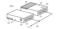
個々のパワー素子部23a〜23fは、それぞれ少なくとも1組のスイッチング素子31,32を備える。各パワー素子部23a〜23fの例として、1個のパワー素子部23aを図4に示す。このパワー素子部23aは、図4の如く、図21中の符号3a,3b,3cに相当するハイアーム側スイッチング素子(第1のスイッチング素子)31と、同じく符号4a,4b,4cに相当するローアーム側スイッチング素子(第2のスイッチング素子)32とが対になってそれぞれ構成され、この一対のスイッチング素子31,32から構成される各パワー素子部23a〜23fが、モータ12の6個の各モータコイル12a〜12fにそれぞれ一対一に対応して、当該各モータコイル12a〜12fの接続端子9に近傍する位置にそれぞれ設置される。また、他のパワー素子部23b〜23fも図4に示したパワー素子部23aと同様の構成である。各パワー素子部23a〜23fの各スイッチング素子31,32は、例えばNチャネルのパワーMOSFET、JFET、IGBTまたはSiC、GaN、Cなどの高温動作可能なワイドバンドギャップデバイス等が使用される。   Each power element part 23a-23f is provided with at least 1 set of switching elements 31 and 32, respectively. As an example of each power element part 23a-23f, one power element part 23a is shown in FIG. As shown in FIG. 4, the power element portion 23a includes a high arm side switching element (first switching element) 31 corresponding to reference numerals 3a, 3b, and 3c in FIG. 21, and a low arm corresponding to reference numerals 4a, 4b, and 4c. The side switching elements (second switching elements) 32 are paired, and each of the power element portions 23a to 23f including the pair of switching elements 31 and 32 includes the six motors of the motor 12. Corresponding to the coils 12a to 12f on a one-to-one basis, the coils 12a to 12f are respectively installed at positions near the connection terminals 9 of the motor coils 12a to 12f. Further, the other power element portions 23b to 23f have the same configuration as the power element portion 23a shown in FIG. As each switching element 31 and 32 of each power element part 23a-23f, the wide band gap device etc. which can be operated at high temperature, such as N channel power MOSFET, JFET, IGBT or SiC, GaN, C, etc. are used, for example.

これらのスイッチング素子31,32は、ベアチップを適用しても差し支えないが、組立性を考慮し、組み立て構造のパッケージが用いられる。このようにパッケージ構造を採用することにより、パッケージ間の空間を空冷スペースとして利用できる利点がある。   These switching elements 31 and 32 may be bare chips, but an assembly structure package is used in consideration of assembly. By adopting the package structure in this way, there is an advantage that the space between the packages can be used as an air cooling space.

この各パワー素子部23a〜23f内の一対のスイッチング素子31,32は、ソースとドレインの関係が逆転すること以外は、互いに同一の素子構造を有している。具体的に、図4に示したパワー素子部23aのハイアーム側スイッチング素子31は、底面にドレイン電極33が形成され、一側面にソース電極34が形成され、他の側面にゲート電極35が形成された箱形の部材として構成されており、また、ローアーム側スイッチング素子32は、上面にソース電極36が形成され、一側面にドレイン電極37が形成され、他の側面にゲート電極38が形成された箱形の部材として構成されている。ただし、ハイアーム側スイッチング素子31のドレイン電極33とローアーム側スイッチング素子32のソース電極36とは実際には同一の構成であって、また、ハイアーム側スイッチング素子31のソース電極34とローアーム側スイッチング素子32ドレイン電極37とも実際には同一の構成である。即ち、両スイッチング素子31,32は同一の構造を有する部品を、互いに天地が逆転するように設置されるだけで、それぞれのスイッチング素子31,32がハイアーム側スイッチング素子31とローアーム側スイッチング素子32として機能するものである。この点について、他のパワー素子部23b〜23fも、図4に示したパワー素子部23aと同様である。   The pair of switching elements 31 and 32 in each of the power element units 23a to 23f have the same element structure except that the relationship between the source and the drain is reversed. Specifically, the high arm side switching element 31 of the power element unit 23a shown in FIG. 4 has a drain electrode 33 formed on the bottom surface, a source electrode 34 formed on one side surface, and a gate electrode 35 formed on the other side surface. The low arm side switching element 32 has a source electrode 36 formed on the upper surface, a drain electrode 37 formed on one side surface, and a gate electrode 38 formed on the other side surface. It is configured as a box-shaped member. However, the drain electrode 33 of the high arm side switching element 31 and the source electrode 36 of the low arm side switching element 32 are actually the same configuration, and the source electrode 34 of the high arm side switching element 31 and the low arm side switching element 32 are the same. The drain electrode 37 actually has the same configuration. That is, the switching elements 31 and 32 are simply installed with components having the same structure so that the top and the bottom are reversed, and the switching elements 31 and 32 are formed as a high arm side switching element 31 and a low arm side switching element 32, respectively. It functions. In this regard, the other power element portions 23b to 23f are the same as the power element portion 23a shown in FIG.

そして、ハイアーム側スイッチング素子31のソース電極34と、ローアーム側スイッチング素子32のドレイン電極37とが同一方向に臨むように並置され、さらにハイアーム側スイッチング素子31のソース電極34とローアーム側スイッチング素子32のドレイン電極37とが、図3に示した出力端子39に共に接続される。   The source electrode 34 of the high arm side switching element 31 and the drain electrode 37 of the low arm side switching element 32 are juxtaposed so as to face in the same direction, and the source electrode 34 of the high arm side switching element 31 and the low arm side switching element 32 The drain electrode 37 is connected to the output terminal 39 shown in FIG.

そして、出力端子39は、モータ12の6個のモータコイル12a〜12fのうち最も近傍に配置されるモータコイル12a〜12f(図1)の接続端子9に直接に係合するなどして接続される。   The output terminal 39 is connected, for example, by directly engaging the connection terminal 9 of the motor coils 12a to 12f (FIG. 1) arranged closest to the six motor coils 12a to 12f of the motor 12. The

また、ハイアーム側スイッチング素子31のドレイン電極37は、ハンダまたは導電接着材により第1環状導体21に面接続され、またローアーム側スイッチング素子32のソース電極34はハンダまたは導電接着材により第2環状導体22に面接続される。   Further, the drain electrode 37 of the high arm side switching element 31 is surface-connected to the first annular conductor 21 by solder or conductive adhesive, and the source electrode 34 of the low arm side switching element 32 is connected to the second annular conductor by solder or conductive adhesive. 22 is surface-connected.

さらに、各スイッチング素子31,32のゲート35,38は、図21中の制御入力端子であるゲート端子7a,7b,7c,8a,8b,8cに相当する接続部材41(図3)を通じて、個別にフラットケーブル等の電線束42として束ねられた複数の制御線42a〜42f(図4)のいずれかに個々に接続される。   Furthermore, the gates 35 and 38 of the switching elements 31 and 32 are individually connected through the connection members 41 (FIG. 3) corresponding to the gate terminals 7a, 7b, 7c, 8a, 8b, and 8c, which are control input terminals in FIG. Are individually connected to any one of a plurality of control lines 42 a to 42 f (FIG. 4) bundled as a wire bundle 42 such as a flat cable.

この環状パワーモジュール11のモータ12が6個のモータコイル12a〜12fを有する回路構成例を示した図が図5である。尚、ハイアーム側スイッチング素子31及びローアーム側スイッチング素子32の符号を1個のパワー素子部23aのみ表示し、他のパワー素子部23b〜23fについては符号31,32を省略しているが、他のパワー素子部23b〜23fも同様にハイアーム側スイッチング素子31及びローアーム側スイッチング素子32を備えていることに変わりはない。   FIG. 5 shows a circuit configuration example in which the motor 12 of the annular power module 11 has six motor coils 12a to 12f. In addition, although the code | symbol of the high arm side switching element 31 and the low arm side switching element 32 displays only one power element part 23a, the code | symbols 31 and 32 are abbreviate | omitted about the other power element parts 23b-23f, Similarly, the power element portions 23b to 23f also include the high arm side switching element 31 and the low arm side switching element 32.

図5において、第1のパワー素子部23aと第4のパワー素子部23dがモータ12のU相のスイッチ切替を行い、第2のパワー素子部23bと第5のパワー素子部23eがモータ12のV相のスイッチ切替を行い、第3のパワー素子部23cと第6のパワー素子部23fがモータ12のW相のスイッチ切替を行うよう、各相のモータコイル12a〜12fに近傍して配置されている。   In FIG. 5, the first power element unit 23 a and the fourth power element unit 23 d switch the U phase of the motor 12, and the second power element unit 23 b and the fifth power element unit 23 e The V-phase switch is switched, and the third power element unit 23c and the sixth power element unit 23f are arranged close to the motor coils 12a to 12f of the respective phases so that the W-phase switch switching of the motor 12 is performed. ing.

また、全てのパワー素子部23a〜23fにおいて、ハイアーム側スイッチング素子31のドレイン電極33が第1環状導体21に共通に接続され、さらに、全てのパワー素子部23a〜23fにおいて、ローアーム側スイッチング素子32のソース電極36が第2環状導体22に共通に接続されている。そして、第1環状導体21は直流電源側であるP(+)端子45(図6参照)に接続され、第2環状導体22は接地側であるN(−)端子46(図6参照)に接続される。   In all the power element units 23a to 23f, the drain electrode 33 of the high arm side switching element 31 is connected in common to the first annular conductor 21, and in all the power element units 23a to 23f, the low arm side switching element 32 is connected. Source electrodes 36 are connected to the second annular conductor 22 in common. The first annular conductor 21 is connected to the P (+) terminal 45 (see FIG. 6) on the DC power supply side, and the second annular conductor 22 is connected to the N (−) terminal 46 (see FIG. 6) on the ground side. Connected.

そして、図5の如く、U相の第1及び第4のパワー素子部23a,23dは、そのハイアーム側スイッチング素子31の各ゲート電極35が共に第1の制御線42aに接続され、同じくそのローアーム側スイッチング素子32の各ゲート電極38が共に第2の制御線42bに接続される。また、V相の第2及び第5のパワー素子部23b,23eは、そのハイアーム側スイッチング素子31の各ゲート電極35が共に第3の制御線42cに接続され、同じくそのローアーム側スイッチング素子32の各ゲート電極38が共に第4の制御線42dに接続される。さらにW相の第3及び第6のパワー素子部23c,23fは、そのハイアーム側スイッチング素子31の各ゲート電極35が共に第5の制御線42eに接続され、同じくそのローアーム側スイッチング素子32の各ゲート電極38が共に第6の制御線42fに接続される。このように構成することで、インバータ装置としての環状パワーモジュール11では、各制御線42a〜42fからの信号により、U相、V相及びW相の三相毎に、ハイアーム側スイッチング素子31のオンオフとローアーム側スイッチング素子32のオンオフを行うことができる。尚、図5中の符号UHはU相のハイアーム側スイッチング素子31をオンオフするための制御信号、符号ULはU相のローアーム側スイッチング素子32をオンオフするための制御信号、符号VHはV相のハイアーム側スイッチング素子31をオンオフするための制御信号、符号VLはV相のローアーム側スイッチング素子32をオンオフするための制御信号、符号WHはW相のハイアーム側スイッチング素子31をオンオフするための制御信号、符号WLはW相のローアーム側スイッチング素子32をオンオフするための制御信号をそれぞれ示している。これらの制御信号UH,UL,VH,VL,WH,WLは、PWM制御信号として与えられる。   As shown in FIG. 5, in the U-phase first and fourth power element portions 23a and 23d, the gate electrodes 35 of the high arm side switching element 31 are both connected to the first control line 42a. Both gate electrodes 38 of the side switching element 32 are connected to the second control line 42b. In the V-phase second and fifth power element portions 23b and 23e, the gate electrodes 35 of the high arm side switching element 31 are both connected to the third control line 42c. Both gate electrodes 38 are connected to the fourth control line 42d. Further, in the W-phase third and sixth power element portions 23c and 23f, each gate electrode 35 of the high arm side switching element 31 is connected to the fifth control line 42e, and each of the low arm side switching element 32 is also connected. Both gate electrodes 38 are connected to the sixth control line 42f. With this configuration, in the annular power module 11 as the inverter device, the high arm side switching element 31 is turned on / off for each of the three phases of the U phase, the V phase, and the W phase by signals from the control lines 42a to 42f. The low arm side switching element 32 can be turned on and off. In FIG. 5, symbol UH is a control signal for turning on / off the U-phase high-arm side switching element 31, symbol UL is a control signal for turning on / off the U-phase low-arm side switching device 32, and symbol VH is V-phase. A control signal for turning on / off the high-arm side switching element 31, VL is a control signal for turning on / off the V-phase low-arm side switching element 32, and WH is a control signal for turning on / off the W-phase high-arm side switching element 31. Symbol WL denotes a control signal for turning on / off the W-phase low arm side switching element 32. These control signals UH, UL, VH, VL, WH and WL are given as PWM control signals.

そして、環状パワーモジュール11は、同心円上に配置された一対の環状導体21,22と、6個のパワー素子部23a〜23fと、制御線42a〜42f用の電線束42とが、例えば図6に示したような絶縁樹脂製の封止保護体47によって封止される。尚、図6中の符号49aは、図5に示した電線束42の各制御線42a〜42fに制御信号UH,UL,VH,VL,WH,WLを入力するための制御信号入力端子48が設置される制御信号入力コネクタである。そして、図5に示した外部接続用のP(+)端子45、N(−)端子46及び制御信号入力端子48が備えられたコネクタ部49aのみが、封止保護体47から外部に対して接続可能に露出されるように構成される。   The annular power module 11 includes a pair of annular conductors 21 and 22 arranged concentrically, six power element portions 23a to 23f, and a wire bundle 42 for control lines 42a to 42f, for example, as shown in FIG. It is sealed by a sealing protector 47 made of an insulating resin as shown in FIG. In addition, the code | symbol 49a in FIG. 6 has the control signal input terminal 48 for inputting control signal UH, UL, VH, VL, WH, WL to each control line 42a-42f of the wire bundle 42 shown in FIG. A control signal input connector to be installed. And only the connector part 49a provided with the P (+) terminal 45, N (-) terminal 46 and control signal input terminal 48 for external connection shown in FIG. Configured to be connectably exposed.

尚、望ましくは、制御信号入力端子48のコネクタ部49aに、制御信号UH,UL,VH,VL,WH,WLを入力するための外部の制御部(図示省略)のユニットが直接嵌合接続される。これにより、環状パワーモジュール11と制御部との間の配線が省略され、更に省スペース化が実現できるものである。   Preferably, a unit of an external control unit (not shown) for inputting the control signals UH, UL, VH, VL, WH, WL is directly fitted and connected to the connector 49a of the control signal input terminal 48. The Thereby, wiring between the annular power module 11 and the control unit is omitted, and further space saving can be realized.

<使用方法>
上記構成の環状パワーモジュール11は、図1及び図5の如く、モータ12の外周に設置され、各パワー素子部23a〜23fの出力端子39(図3)が、モータ12の6個のモータコイル12a〜12fのうち最も近傍に配置されるモータコイル12a〜12f(図1)の接続端子9に直接係合するなどして接続される。
<How to use>
As shown in FIGS. 1 and 5, the annular power module 11 having the above configuration is installed on the outer periphery of the motor 12, and the output terminals 39 (FIG. 3) of the power element portions 23 a to 23 f are the six motor coils of the motor 12. The motor coils 12a to 12f (FIG. 1) arranged closest to the terminals 12a to 12f are connected by direct engagement or the like.

そして、所定の制御部(図示省略)からの制御信号UH,UL,VH,VL,WH,WLが制御信号入力端子48に与えられると、この制御信号UH,UL,VH,VL,WH,WLは、電線束42の制御線42a〜42f(図4及び図5)を通じて各パワー素子部23a〜23fの各スイッチング素子31,32にゲート入力され、この制御信号UH,UL,VH,VL,WH,WLに応じたタイミングで、各パワー素子部23a〜23fの各スイッチング素子31,32がオンオフする。   When control signals UH, UL, VH, VL, WH, WL from a predetermined control unit (not shown) are supplied to the control signal input terminal 48, the control signals UH, UL, VH, VL, WH, WL Are gate-input to the switching elements 31 and 32 of the power element portions 23a to 23f through the control lines 42a to 42f (FIGS. 4 and 5) of the wire bundle 42, and the control signals UH, UL, VH, VL, WH. , WL, the switching elements 31, 32 of the power element units 23a-23f are turned on and off.

そして、この環状パワーモジュール11がモータ12の外周の全周に亘って配置され、さらに各パワー素子部23a〜23fの出力端子39(図3)が、モータ12の6個のモータコイル12a〜12fのうち最も近傍に配置されるモータコイル12a〜12f(図1)の接続端子9に直接接続されるため、図22のようにインバータ装置1とモータ2とを互いに別個独立したユニットとして個別に構成していた従来例に比べて、パワーケーブル10a,10b,10cを配線する必要がなくなる。したがって、パワーケーブル10a,10b,10cの省略によりスペース効率を大幅に向上することができる。   And this annular power module 11 is arrange | positioned over the perimeter of the motor 12, and also the output terminal 39 (FIG. 3) of each power element part 23a-23f is six motor coils 12a-12f of the motor 12. 22 are directly connected to the connection terminals 9 of the motor coils 12a to 12f (FIG. 1) arranged closest to each other, so that the inverter device 1 and the motor 2 are individually configured as separate and independent units as shown in FIG. Compared to the conventional example, the power cables 10a, 10b, and 10c need not be wired. Therefore, the space efficiency can be greatly improved by omitting the power cables 10a, 10b, and 10c.

また、従来では、インバータ装置1とモータ2のそれぞれに冷却装置を設置する必要があったが、この実施形態では、環状パワーモジュール11をモータ12の外周に近接配置しているので、モータ12に対する冷却装置と環状パワーモジュール11に対する冷却装置とを共用することができる。例えば、水または油等の冷媒を配管を通して冷却する場合の配管の設置スペースが少なくて済み、あるいは、空冷する場合は空冷スペースが少なくて済む。したがって、冷却装置についてのスペース効率をも向上することができる。   Conventionally, it has been necessary to install a cooling device in each of the inverter device 1 and the motor 2. However, in this embodiment, the annular power module 11 is disposed close to the outer periphery of the motor 12. The cooling device and the cooling device for the annular power module 11 can be shared. For example, the installation space for piping when cooling a coolant such as water or oil through the piping is small, or the air cooling space is small when cooling with air. Therefore, the space efficiency for the cooling device can also be improved.

そして、両環状導体21,22の間の間隙や、モータ12と第1環状導体21との間の間隙を空冷スペースとして利用できる利点もある。   There is also an advantage that the gap between the two annular conductors 21 and 22 and the gap between the motor 12 and the first annular conductor 21 can be used as an air cooling space.

さらに、両環状導体21,22が、モータ12の外周の全周に亘って形成されているので、パワー素子部23a〜23fの冷却部材として空気接触面積を大きくとることができ便利である。   Furthermore, since both the annular conductors 21 and 22 are formed over the entire circumference of the outer periphery of the motor 12, a large air contact area can be conveniently used as a cooling member for the power element portions 23a to 23f.

さらにまた、環状パワーモジュール11内で環状導体21,22の任意の位置にパワー素子部23a〜23fを設置することが可能であるので、相数を増加するなどの回路設計上の変更を行う場合に、製造工程においてその設計変更に容易に対応できるだけでなく、従来のようにパワーケーブルを新たに配線する必要がないため、便利である。   Furthermore, since it is possible to install the power element portions 23a to 23f at arbitrary positions of the annular conductors 21 and 22 in the annular power module 11, a change in circuit design such as increasing the number of phases is performed. In addition, not only can the design change be easily accommodated in the manufacturing process, but it is also convenient because it is not necessary to newly wire the power cable as in the prior art.

これらのことから、パワーモジュール11及びモータ12が設置される部位のスペース効率を向上するとともに、モータ12の相数を容易に変更することが可能となる。   As a result, the space efficiency of the part where the power module 11 and the motor 12 are installed can be improved, and the number of phases of the motor 12 can be easily changed.

また、接地側の第2環状導体22を第1環状導体21より外周側に配置しているので、この第2環状導体22を自動車のボディ等の接地部位に容易に接続でき、配線効率が向上する。   Further, since the second annular conductor 22 on the ground side is arranged on the outer peripheral side from the first annular conductor 21, the second annular conductor 22 can be easily connected to a grounding part such as a body of an automobile, and the wiring efficiency is improved. To do.

さらに、制御信号入力端子48のコネクタ部49aに、制御信号UH,UL,VH,VL,WH,WLを入力するための外部の制御部(図示省略)のユニットが直接嵌合接続される場合は、環状パワーモジュール11と制御部との間の配線が省略され、更に省スペース化が実現できる。   Further, when a unit of an external control unit (not shown) for inputting control signals UH, UL, VH, VL, WH, WL is directly fitted and connected to the connector portion 49a of the control signal input terminal 48. The wiring between the annular power module 11 and the control unit is omitted, and further space saving can be realized.

さらにまた、スイッチング素子31,32のパッケージ間の空間を空冷スペースとして利用できる利点がある。   Furthermore, there is an advantage that the space between the packages of the switching elements 31 and 32 can be used as an air cooling space.

尚、この実施形態において、各パワー素子部23a〜23fの各スイッチング素子31,32の配置構成が、図4のように互いに側方に並置するようになっているが、その他、図7のように、上下方向に積層して配置してもよい。この場合においても、ハイアーム側スイッチング素子31のソース電極34と、ローアーム側スイッチング素子32のドレイン電極37とが同一方向に臨むように積層され、さらにハイアーム側スイッチング素子31のソース電極34とローアーム側スイッチング素子32のドレイン電極37とが、図3に示した出力端子39に共に接続される。また、ハイアーム側スイッチング素子31のドレイン電極37は、ハンダまたは導電接着材により第1環状導体21に面接続され、またローアーム側スイッチング素子32のソース電極34はハンダまたは導電接着材により第2環状導体22に面接続される。   In this embodiment, the arrangements of the switching elements 31 and 32 of the power element units 23a to 23f are arranged side by side as shown in FIG. Alternatively, they may be stacked in the vertical direction. Also in this case, the source electrode 34 of the high arm side switching element 31 and the drain electrode 37 of the low arm side switching element 32 are stacked so as to face in the same direction, and the source electrode 34 of the high arm side switching element 31 and the low arm side switching are stacked. The drain electrode 37 of the element 32 is connected together to the output terminal 39 shown in FIG. Further, the drain electrode 37 of the high arm side switching element 31 is surface-connected to the first annular conductor 21 by solder or conductive adhesive, and the source electrode 34 of the low arm side switching element 32 is connected to the second annular conductor by solder or conductive adhesive. 22 is surface-connected.

かかる図7の構成を採用しても、図4の構成と同様の効果を得ることができる。   Even if the configuration of FIG. 7 is adopted, the same effect as that of the configuration of FIG. 4 can be obtained.

{第2の実施の形態}
図8は本発明の第2の実施の形態に係る環状パワーモジュール11の複数のパワー素子部23a〜23fのうちの1個(23a)を示す側面視断面図、図9は同じくその金属配線を中心とした展開図である。尚、この実施形態においては、上記の第1の実施の形態と同様の機能を有する要素については同一符号を付している。
{Second Embodiment}
FIG. 8 is a side sectional view showing one (23a) of the plurality of power element portions 23a to 23f of the annular power module 11 according to the second embodiment of the present invention, and FIG. FIG. In this embodiment, elements having the same functions as those in the first embodiment are given the same reference numerals.

このパワー素子部23aは、図8及び図9の如く、組み立て構造のパッケージ構造としたもので、ハイアーム側スイッチング素子である第1のスイッチング素子(パワーMOSFET、JFET、IGBTまたはSiC、GaN、Cなどの高温動作可能なワイドバンドギャップデバイス等)51の下面に形成されたドレイン電極が、第1の導電板52の上面にハンダまたは導電接着材を用いてマウント接続され、またローアーム側スイッチング素子である第2のスイッチング素子(パワーMOSFET、JFET、IGBTまたはSiC、GaN、Cなどの高温動作可能なワイドバンドギャップデバイス等)53の下面に形成されたドレイン電極が、第2の導電板54の上面にハンダまたは導電接着材を用いてマウント接続されている。第1の導電板52と第2の導電板54とは、非接続で並置される。   As shown in FIGS. 8 and 9, the power element portion 23a has a package structure of an assembly structure, and is a first switching element (power MOSFET, JFET, IGBT or SiC, GaN, C, etc.) which is a high arm side switching element. The drain electrode formed on the lower surface of the first conductive plate 52 is mounted and connected to the upper surface of the first conductive plate 52 using solder or a conductive adhesive, and is a low arm side switching element. The drain electrode formed on the lower surface of the second switching element 53 (power MOSFET, JFET, IGBT or wide band gap device such as SiC, GaN, C or the like capable of operating at high temperature) 53 is formed on the upper surface of the second conductive plate 54. The mount connection is made using solder or conductive adhesive. The first conductive plate 52 and the second conductive plate 54 are juxtaposed without being connected.

また、第1のスイッチング素子51の上面に形成されたソース電極は、金属片等の接続部材55を通じて第2の導電板54に接続される。これにより、ハイアーム側スイッチング素子(パワーMOSFET、JFET、IGBTまたはSiC、GaN、Cなどの高温動作可能なワイドバンドギャップデバイス等)51のソースとローアーム側スイッチング素子(パワーMOSFET、JFET、IGBTまたはSiC、GaN、Cなどの高温動作可能なワイドバンドギャップデバイス等)53のドレインとが第2の導電板54を通じて接続されていることになる。   The source electrode formed on the upper surface of the first switching element 51 is connected to the second conductive plate 54 through a connection member 55 such as a metal piece. Thereby, the source of the high arm side switching element (power MOSFET, JFET, IGBT or wide band gap device capable of high temperature operation such as SiC, GaN, C, etc.) 51 and the low arm side switching element (power MOSFET, JFET, IGBT or SiC, The drain of 53 (such as a wide band gap device capable of high temperature operation such as GaN and C) is connected through the second conductive plate 54.

そして、この第2の導電板54には、その一方向(図9中の右方向)に向けて、モータ12に接続するための出力端子56が一体的に延設されている。   An output terminal 56 for connecting to the motor 12 is integrally extended on the second conductive plate 54 in one direction (right direction in FIG. 9).

また、このパワー素子部23aには、第1の導電板52及び第2の導電板54のいずれにも非接続に並置された第3の導電板57が設けられている。この第3の導電板57は、金属片等の接続部材58を通じて、第2のスイッチング素子53のソース電極に接続されている。また、この第3の導電板57には、その他方向(図9中の上方向)に向けて、第2のスイッチング素子53のソース電極を接地するための接地用金属部材59が一体的に延設され、この接地用金属部材59が2箇所の折曲線61,62で上面視谷折りに折曲されることにより、接地用金属部材59の一部63が図8のように第1の導電板52と平行に且つ上下逆方向に配置される。   Further, the power element portion 23a is provided with a third conductive plate 57 juxtaposed in a non-connected manner to either the first conductive plate 52 or the second conductive plate 54. The third conductive plate 57 is connected to the source electrode of the second switching element 53 through a connection member 58 such as a metal piece. In addition, a grounding metal member 59 for grounding the source electrode of the second switching element 53 extends integrally with the third conductive plate 57 in the other direction (upward in FIG. 9). The ground metal member 59 is bent into a valley fold when viewed from above at two folding lines 61 and 62, so that a part 63 of the ground metal member 59 has the first conductive property as shown in FIG. It is arranged in parallel with the plate 52 and upside down.

さらに、第1のスイッチング素子51のゲート電極は、リード線等の電線65で一のゲート入力用端子66に接続され、また第2のスイッチング素子53のゲート電極は、リード線等の電線67で一のゲート入力用端子68に接続されている。   Further, the gate electrode of the first switching element 51 is connected to one gate input terminal 66 by a wire 65 such as a lead wire, and the gate electrode of the second switching element 53 is connected by a wire 67 such as a lead wire. It is connected to one gate input terminal 68.

かかる状態で、例えばエポキシ樹脂等の絶縁樹脂により、第1の導電板52の下面、接地用金属部材59の一部63の上面及び出力端子56が外部に露出するよう、略矩形状にモールド成形されて、図8に示したパワー素子部23aが完成する。尚、図8及び図9では、例として一のパワー素子部23aのみを図示しているが、他のパワー素子部23b〜23fも同様の構成とされる。   In this state, for example, an insulating resin such as an epoxy resin is molded into a substantially rectangular shape so that the lower surface of the first conductive plate 52, the upper surface of the part 63 of the ground metal member 59, and the output terminal 56 are exposed to the outside. Thus, the power element portion 23a shown in FIG. 8 is completed. 8 and 9, only one power element unit 23a is illustrated as an example, but the other power element units 23b to 23f have the same configuration.

ここで、この実施形態のパワー素子部23a〜23fの下面には、ハイアーム側スイッチング素子である第1のスイッチング素子51のドレイン電極が接続された第1の導電板52が露出されており、この第1の導電板52は、図7に示したパワー素子部23aの符号33(ハイアーム側スイッチング素子31ドレイン電極)に相当する。   Here, the first conductive plate 52 to which the drain electrode of the first switching element 51 which is a high arm side switching element is connected is exposed on the lower surfaces of the power element portions 23a to 23f of this embodiment. The first conductive plate 52 corresponds to the reference numeral 33 (high arm side switching element 31 drain electrode) of the power element portion 23a shown in FIG.

また、この実施形態のパワー素子部23a〜23fの上面には、ローアーム側スイッチング素子である第2のスイッチング素子53のソース電極が接続された接地用金属部材59が露出されており、この接地用金属部材59は、図7に示したパワー素子部23aの符号36(ローアーム側スイッチング素子32のソース電極)に相当する。   Further, the ground metal member 59 to which the source electrode of the second switching element 53 which is the low arm side switching element is connected is exposed on the upper surfaces of the power element portions 23a to 23f of this embodiment. The metal member 59 corresponds to the reference numeral 36 (the source electrode of the low arm side switching element 32) of the power element portion 23a shown in FIG.

また、この実施形態のパワー素子部23a〜23fの出力端子56は、図7に示したパワー素子部23aの出力端子39に相当する。   Further, the output terminals 56 of the power element units 23a to 23f of this embodiment correspond to the output terminal 39 of the power element unit 23a shown in FIG.

そして、図1及び図5に示した第1の実施の形態と同様に、各パワー素子部23a〜23fのハイアーム側スイッチング素子である第1のスイッチング素子51のドレインに接続された第1の導電板52が、第1環状導体21に面接続されて直流電源側であるP(+)端子45に接続され、またローアーム側スイッチング素子である第2のスイッチング素子53のソースに接続された接地用金属部材59が、接地側であるN(−)端子46に接続される。   As in the first embodiment shown in FIGS. 1 and 5, the first conductive connected to the drain of the first switching element 51 which is the high arm side switching element of each power element portion 23a to 23f. The plate 52 is ground-connected to the first annular conductor 21 and connected to the P (+) terminal 45 on the DC power supply side, and connected to the source of the second switching element 53 that is the low arm side switching element. A metal member 59 is connected to the N (−) terminal 46 on the ground side.

その他の構成は第1の実施の形態と同様である。   Other configurations are the same as those of the first embodiment.

このような構成の第2の実施の形態によると、第1の実施の形態と同様の回路構造を取ることができ、よって同様の効果を得ることができる。さらに、この実施形態では、第1のスイッチング素子51と第2のスイッチング素子53とを同一のパッケージとして一体的に構成しているので、各パワー素子部23a〜23fとしての取り扱いに便利である。   According to the second embodiment having such a configuration, a circuit structure similar to that of the first embodiment can be obtained, and thus the same effect can be obtained. Further, in this embodiment, the first switching element 51 and the second switching element 53 are integrally configured as the same package, which is convenient for handling as the power element portions 23a to 23f.

尚、この実施形態では、絶縁樹脂等によりモールドしていたが、両スイッチング素子51,53を一体的にパッケージとして取り扱うことが可能であれば、どのような構成であってもよい。   In this embodiment, the resin is molded with an insulating resin or the like. However, any configuration may be used as long as both switching elements 51 and 53 can be handled as a package integrally.

{第3の実施の形態}
図10は本発明の第3の実施の形態に係る環状パワーモジュール11の一部拡大側面図である。なお、図10では第1の実施の形態と同様の機能を有する要素については同一符号を付している。
{Third embodiment}
FIG. 10 is a partially enlarged side view of the annular power module 11 according to the third embodiment of the present invention. In FIG. 10, elements having the same functions as those in the first embodiment are denoted by the same reference numerals.

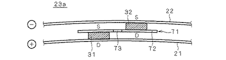
この実施の形態の環状パワーモジュール11は、各パワー素子部23a〜23fにおいて、ハイアーム側スイッチング素子(第1のスイッチング素子)31とローアーム側スイッチング素子(第2のスイッチング素子)32とを、出力端子71を介装して縦方向に積層した構成となっている。尚、図10では、例として一のパワー素子部23aについてのみ図示しているが、他のパワー素子部23b〜23fにおいても同様の構成となる。   The annular power module 11 of this embodiment includes a high arm side switching element (first switching element) 31 and a low arm side switching element (second switching element) 32 in each of the power element units 23a to 23f. 71 is interposed in the vertical direction. In FIG. 10, only one power element unit 23a is illustrated as an example, but the other power element units 23b to 23f have the same configuration.

ハイアーム側スイッチング素子31の下面には、ドレイン電極Dが形成され、このドレイン電極Dが、ハンダまたは導電接着材等により第1環状導体21の外周面に面接続されている。   A drain electrode D is formed on the lower surface of the high arm side switching element 31, and the drain electrode D is surface-connected to the outer peripheral surface of the first annular conductor 21 by solder or a conductive adhesive.

またハイアーム側スイッチング素子31の上面にはソース電極Sが形成されており、そのソース電極Sが、ハンダまたは導電接着材等により出力端子71の下面に面接続されている。   Further, a source electrode S is formed on the upper surface of the high arm side switching element 31, and the source electrode S is surface-connected to the lower surface of the output terminal 71 by solder or conductive adhesive.

さらに、ローアーム側スイッチング素子32の上面には、ソース電極Sが形成され、このソース電極Sが、ハンダまたは導電接着材等により第2環状導体22の内周面に面接続されている。   Further, a source electrode S is formed on the upper surface of the low arm side switching element 32, and the source electrode S is surface-connected to the inner peripheral surface of the second annular conductor 22 by solder or a conductive adhesive.

さらにまた、ローアーム側スイッチング素子32の下面には、ドレイン電極Dが形成され、このドレイン電極Dが、ハンダまたは導電接着材等により出力端子71の上面に面接続されている。   Furthermore, a drain electrode D is formed on the lower surface of the low arm side switching element 32, and this drain electrode D is surface-connected to the upper surface of the output terminal 71 by solder or a conductive adhesive or the like.

各スイッチング素子31,32のゲート電極は、それぞれの側面に形成されており、第1の実施の形態と同様に、これらのゲート電極はフラットケーブル等の電線束を通じて外部の制御部からの制御信号を受けるように構成される。ただし、各スイッチング素子31,32のゲート電極、電線束及び外部の制御部は、図10においては図示省略している。   The gate electrodes of the switching elements 31 and 32 are formed on the respective side surfaces, and as in the first embodiment, these gate electrodes are controlled by an external control unit through a bundle of wires such as a flat cable. Configured to receive. However, the gate electrodes, wire bundles, and external control units of the switching elements 31 and 32 are not shown in FIG.

出力端子71は、図11に示すような形状の金属片で構成されており、その両面で両スイッチング素子31,32に面接続するための基部72と、この基部の中央部から側方に張り出して形成されてリード線等に接続するための接続部73とが一体的に形成されてなる。接続部73は、リード線等を通じてモータ12の各相に接続される。   The output terminal 71 is composed of a metal piece having a shape as shown in FIG. 11, and a base 72 for surface connection to both switching elements 31 and 32 on both sides thereof, and projects from the center of the base to the side. And a connecting portion 73 for connecting to a lead wire or the like. The connection part 73 is connected to each phase of the motor 12 through a lead wire or the like.

その他の構成は第1の実施の形態と同様である。   Other configurations are the same as those of the first embodiment.

この実施形態においても、第1の実施の形態と同様の回路構造を取ることができ、よって同様の効果を得ることができる。さらに、この実施形態では、極めて簡単な構成を実現できる利点がある。   Also in this embodiment, the same circuit structure as that of the first embodiment can be taken, and thus the same effect can be obtained. Furthermore, this embodiment has an advantage that an extremely simple configuration can be realized.

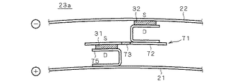
尚、この実施形態では、各パワー素子部23a〜23fにおいて、ハイアーム側スイッチング素子31とローアーム側スイッチング素子32とを、出力端子71を介装して縦方向に積層した構成としているが、例えば、図12の如く、ハイアーム側スイッチング素子31とローアーム側スイッチング素子32とを出力端子71の基部72の長手方向にずらして配置しても差し支えない。この場合は、各スイッチング素子31,32の外径の寸法誤差や、両環状導体21,22の配置状の寸法誤差が生じた場合でも、これらの寸法誤差を、出力端子71の配置角度が僅かに変わるだけで吸収することができ便利である。   In this embodiment, each of the power element portions 23a to 23f has a configuration in which the high arm side switching element 31 and the low arm side switching element 32 are stacked in the vertical direction with the output terminal 71 interposed therebetween. As shown in FIG. 12, the high arm side switching element 31 and the low arm side switching element 32 may be shifted in the longitudinal direction of the base portion 72 of the output terminal 71. In this case, even if a dimensional error in the outer diameter of each switching element 31, 32 or a dimensional error in the arrangement of the two annular conductors 21, 22 occurs, the dimensional error is slightly reduced by the arrangement angle of the output terminal 71. It is convenient because it can be absorbed just by changing to.

{第4の実施の形態}
図13は本発明の第4の実施の形態に係る環状パワーモジュール11を示す図である。なお、図13では第1の実施の形態及び第3の実施の形態と同様の機能を有する要素については同一符号を付している。この実施の形態の環状パワーモジュール11は、ハイアーム側スイッチング素子(第1のスイッチング素子)31の下面のドレイン電極Dと第1環状導体21の内周面との間に、側面視コ字形の導電性の緩衝部材75を設けるとともに、ローアーム側スイッチング素子(第2のスイッチング素子)32の下面のドレイン電極Dと出力端子71の上面との間にも、同様の緩衝部材76を設ける。緩衝部材75,76としては、例えば1枚の金属片を側面視コ字形になるよう折曲形成したものが適用される。その他の構成は第3の実施の形態と同様である。
{Fourth embodiment}
FIG. 13 is a diagram showing an annular power module 11 according to the fourth embodiment of the present invention. In FIG. 13, elements having the same functions as those in the first embodiment and the third embodiment are denoted by the same reference numerals. The annular power module 11 of this embodiment has a U-shaped conduction between the drain electrode D on the lower surface of the high arm side switching element (first switching element) 31 and the inner peripheral surface of the first annular conductor 21. A similar buffer member 75 is provided between the drain electrode D on the lower surface of the low arm side switching element (second switching element) 32 and the upper surface of the output terminal 71. As the buffer members 75 and 76, for example, one metal piece bent so as to have a U-shape in a side view is applied. Other configurations are the same as those of the third embodiment.

かかる構成によると、自動車に環状パワーモジュール11を搭載する場合、走行中に生じる振動を緩衝部材75,76が吸収するため、耐久性に優れた環状パワーモジュール11を提供することができる。   According to such a configuration, when the annular power module 11 is mounted on an automobile, the shock-absorbing members 75 and 76 absorb vibrations generated during traveling, so that the annular power module 11 having excellent durability can be provided.

また、第1環状導体21と第2環状導体22との間隙に対して、各スイッチング素子31,32の高さ寸法が低すぎる場合に、これらの間隙内で両スイッチング素子31,32を支障なく接続するための中継端子として機能する。このため、スイッチング素子31,32の高さ寸法を気にすることなく両環状導体21,22を配置することができ、設計が容易になる。   Moreover, when the height dimension of each switching element 31 and 32 is too low with respect to the gap | interval of the 1st cyclic | annular conductor 21 and the 2nd cyclic | annular conductor 22, both switching elements 31 and 32 do not have trouble in these gaps. Functions as a relay terminal for connection. For this reason, both the annular conductors 21 and 22 can be arranged without worrying about the height dimension of the switching elements 31 and 32, and the design becomes easy.

尚、この実施形態では、各パワー素子部23a〜23fとして、1個のハイアーム側スイッチング素子31と1個のローアーム側スイッチング素子32を使用していたが、例えば図14のように、複数のハイアーム側スイッチング素子31a,31bと複数のローアーム側スイッチング素子32a,32bをそれぞれ並列に接続してもよい。この場合であっても、緩衝部材75,76を用いて振動を吸収し、また高さ寸法の調整を容易に行うことができる。   In this embodiment, one high arm side switching element 31 and one low arm side switching element 32 are used as the power element units 23a to 23f. However, as shown in FIG. The side switching elements 31a and 31b and the plurality of low arm side switching elements 32a and 32b may be connected in parallel. Even in this case, the vibration can be absorbed by using the buffer members 75 and 76 and the height can be easily adjusted.

また、この実施形態では、緩衝部材75,76を、各スイッチング素子31,32のドレイン電極D側に接続していたが、それぞれのスイッチング素子31,32のソース電極S側に接続しても差し支えないことは言うまでもない。   In this embodiment, the buffer members 75 and 76 are connected to the drain electrode D side of the switching elements 31 and 32. However, the buffer members 75 and 76 may be connected to the source electrode S side of the switching elements 31 and 32. It goes without saying that there is nothing.

{第5の実施の形態}
図15は本発明の第5の実施の形態に係る環状パワーモジュール11を示す模式図、図16は同じくその回路図である。なお、図15及び図16では第1の実施の形態〜第4の実施の形態と同様の機能を有する要素については同一符号を付している。
{Fifth embodiment}
FIG. 15 is a schematic diagram showing an annular power module 11 according to a fifth embodiment of the present invention, and FIG. 16 is a circuit diagram thereof. In FIG. 15 and FIG. 16, elements having the same functions as those in the first to fourth embodiments are denoted by the same reference numerals.

この実施の形態の環状パワーモジュール11は、三相交流電動機であるモータ12の外周の全周に亘って設置される点で、上記した第1の実施の形態〜第4の実施の形態と同様であるが、図15及び図16の如く、プラス(+)側電源Pの電位(第1の電位)に接続するバスバーである第1環状導体21と、マイナス(−)側電源Nの電位(第2の電位)に接続するバスバーである第2環状導体22とが互いに同径に形成されて平行に配置され、この平行配置された両環状導体21,22の間に複数のパワー素子部231a〜231d,232a〜232d,233a〜233dが、U相、V相及びW相のそれぞれにおいて複数個ずつ並列に接続されている。   The annular power module 11 of this embodiment is the same as the first to fourth embodiments described above in that it is installed over the entire circumference of the motor 12 that is a three-phase AC motor. However, as shown in FIGS. 15 and 16, the first annular conductor 21 that is a bus bar connected to the potential (first potential) of the plus (+) side power supply P and the potential of the minus (−) side power supply N ( The second annular conductor 22, which is a bus bar connected to the second potential), is formed in parallel with each other and arranged in parallel, and a plurality of power element portions 231 a are arranged between the annular conductors 21 and 22 arranged in parallel. ˜231d, 232a˜232d, 233a˜233d are connected in parallel in the U phase, the V phase, and the W phase.

例えばU相231においては、ハイアーム側スイッチング素子(第1のスイッチング素子)31とローアーム側スイッチング素子(第2のスイッチング素子)32とをそれぞれ備えた4個のパワー素子部231a〜231dが第1環状導体21と第2環状導体22との間に並列に接続され、これらの4個のパワー素子部231a〜231dにおいて、ハイアーム側スイッチング素子(第1のスイッチング素子)31とローアーム側スイッチング素子(第2のスイッチング素子)32との接続点が、U相231用の出力配線71aを通じて出力端子9に接続される。   For example, in the U phase 231, four power element portions 231 a to 231 d each having a high arm side switching element (first switching element) 31 and a low arm side switching element (second switching element) 32 are first annular. The four power element portions 231a to 231d are connected in parallel between the conductor 21 and the second annular conductor 22, and the high arm side switching element (first switching element) 31 and the low arm side switching element (second Of the switching element) 32 is connected to the output terminal 9 through the output wiring 71a for the U-phase 231.

また、V相232及びW相233においても同様であり、それぞれ4個ずつのパワー素子部232a〜232d,233a〜233dが第1環状導体21と第2環状導体22との間に並列に接続され、各パワー素子部232a〜232d,233a〜233dのハイアーム側スイッチング素子(第1のスイッチング素子)31とローアーム側スイッチング素子(第2のスイッチング素子)32との接続点がV相232及びW相233用の出力配線71aに接続される。   The same applies to the V-phase 232 and the W-phase 233, and each of the four power element portions 232 a to 232 d and 233 a to 233 d is connected in parallel between the first annular conductor 21 and the second annular conductor 22. The connection points between the high arm side switching element (first switching element) 31 and the low arm side switching element (second switching element) 32 of the power element units 232a to 232d, 233a to 233d are the V phase 232 and the W phase 233. Connected to the output wiring 71a.

ここで、各パワー素子部231a〜231d,232a〜232d,233a〜233dは、図4、図7、図8、図10、図12、図13及び図14に示したうちのいずれの構成であっても差し支えない。   Here, each of the power element units 231a to 231d, 232a to 232d, and 233a to 233d has any one of the configurations shown in FIGS. 4, 7, 8, 10, 12, 13, and 14. There is no problem.

そして、図17の如く、各相231,232,233において、それぞれのパワー素子部231a〜231d,232a〜232d,233a〜233dは、環状パワーモジュール11の円周方向に沿って均等距離Laだけ離間した状態で一列に配列されている。   As shown in FIG. 17, in each phase 231, 232, and 233, the power element portions 231 a to 231 d, 232 a to 232 d, and 233 a to 233 d are separated by an equal distance La along the circumferential direction of the annular power module 11. Are arranged in a row.

また、各相231,232,233同士の離間距離Lbも均等とされている。   Further, the separation distance Lb between the phases 231, 232, 233 is also made equal.

このように、円環形の環状パワーモジュール11において各相231,232,233の配置を均等距離Lbで離間させ、さらに各相231,232,233の内部のパワー素子部231a〜231d,232a〜232d,233a〜233d同士も均等距離Laで離間させて配置しているので、このように均等距離La,Lbでなく離間させる場合に比べて、環状パワーモジュール11全体の発熱を円周方向に均等に分布させることができ、故に、放熱効率を向上できる。   In this manner, in the annular annular power module 11, the phases 231, 232, 233 are spaced apart by an equal distance Lb, and the power element portions 231 a-231 d, 232 a-232 d inside the phases 231, 232, 233 are further separated. , 233a to 233d are also spaced apart from each other by the equal distance La, so that the heat generation of the entire annular power module 11 is evenly distributed in the circumferential direction as compared to the case where they are separated from each other instead of the equal distances La and Lb. Therefore, the heat dissipation efficiency can be improved.

尚、放熱のための構成としては、図18のように、両環状導体21,22及びパワー素子部231a〜231d,232a〜232d,233a〜233dを封止するための絶縁樹脂製の保持体(封止保護体)47の内部に、両環状導体21,22及びパワー素子部231a〜231d,232a〜232d,233a〜233dから気密状及び水密状に隔離された中空状の冷媒流路81を形成し、その冷媒流路81の一端の冷媒供給孔82から冷媒を供給するとともに、冷媒流路81の他端の冷媒排出孔83から冷媒を排出するようにすればよい。この場合、冷媒は液状のものであっても気体であっても差し支えない。   In addition, as a structure for heat dissipation, as shown in FIG. 18, a holding body made of an insulating resin for sealing both the annular conductors 21 and 22 and the power element portions 231a to 231d, 232a to 232d, and 233a to 233d ( In the inside of the (sealing protector) 47, a hollow refrigerant flow path 81 is formed that is isolated from both the annular conductors 21 and 22 and the power element portions 231a to 231d, 232a to 232d, and 233a to 233d in an airtight and watertight manner. Then, the refrigerant may be supplied from the refrigerant supply hole 82 at one end of the refrigerant flow path 81 and discharged from the refrigerant discharge hole 83 at the other end of the refrigerant flow path 81. In this case, the refrigerant may be liquid or gas.

あるいは、図19のように、第1環状導体21及び第2環状導体22のいずれか一方または両方の内部に、気密状及び水密状に隔離された中空状の冷媒流路85を形成し、その冷媒流路85の一端の冷媒供給孔86から冷媒を供給するとともに、冷媒流路85の他端の冷媒排出孔87から冷媒を排出するようにしてもよい(図19では第2環状導体22の内部にのみ冷媒流路85を形成した例を示している)。この場合も、冷媒は液状のものであっても気体であっても差し支えない。   Alternatively, as shown in FIG. 19, a hollow refrigerant channel 85 that is isolated in an airtight and watertight manner is formed inside one or both of the first annular conductor 21 and the second annular conductor 22. The refrigerant may be supplied from the refrigerant supply hole 86 at one end of the refrigerant flow path 85 and may be discharged from the refrigerant discharge hole 87 at the other end of the refrigerant flow path 85 (in FIG. 19, the second annular conductor 22). An example in which the refrigerant flow path 85 is formed only inside is shown). In this case, the refrigerant may be liquid or gas.

このようにすれば、環状パワーモジュール11の冷却効果を大幅に向上することが可能である。   In this way, the cooling effect of the annular power module 11 can be greatly improved.

以上の各実施形態においては、理解の容易という便宜上の理由から、環状パワーモジュール11をモータ12と別体に構成している例を説明したが、モータ12の外装の内部に環状パワーモジュール11を一体的に形成してもよいことは勿論である。この場合において、モータ12がバスリング型モータである場合、モータ12内のバスリングを、第1環状導体21及び/または第2環状導体22としてそのまま流用すれば、部材の共用化によりコストを削減でき、且つスペース効率が大幅に効率するとともに、単体としてのモータ12にインバータ装置(環状パワーモジュール11)を組み込んだ構成となって取り扱いが極めて便利になる利点がある。   In each of the above embodiments, the example in which the annular power module 11 is configured separately from the motor 12 has been described for the convenience of easy understanding. However, the annular power module 11 is provided inside the exterior of the motor 12. Of course, they may be integrally formed. In this case, when the motor 12 is a bus ring type motor, if the bus ring in the motor 12 is used as the first annular conductor 21 and / or the second annular conductor 22 as it is, the cost can be reduced by sharing the members. In addition, the space efficiency is greatly improved, and the inverter 12 (annular power module 11) is incorporated into the motor 12 as a single unit, so that the handling becomes extremely convenient.

また、上記各実施形態では、第1環状導体21の径を第2環状導体22より小さく設定し、第1環状導体21の外周に第2環状導体22を同心円上に配置していたが、逆に、第1環状導体21の径を第2環状導体22より大きく設定し、第1環状導体21の内周に第2環状導体22を同心円上に配置してもよい。   Moreover, in each said embodiment, although the diameter of the 1st annular conductor 21 was set smaller than the 2nd annular conductor 22, and the 2nd annular conductor 22 was arrange | positioned on the outer periphery of the 1st annular conductor 21, conversely, Alternatively, the diameter of the first annular conductor 21 may be set larger than that of the second annular conductor 22, and the second annular conductor 22 may be arranged concentrically on the inner periphery of the first annular conductor 21.

さらに、上記各実施形態では、第1環状導体21と第2環状導体22とを同心円状に配置していたが、第1環状導体21と第2環状導体22とを同径に形成し、これらを互いに側方に並べて設置して、その間の間隙部分にパワー素子部23a〜23fを介在させるように接続してもよい。   Furthermore, in each said embodiment, although the 1st annular conductor 21 and the 2nd annular conductor 22 were arrange | positioned concentrically, the 1st annular conductor 21 and the 2nd annular conductor 22 are formed in the same diameter, These May be arranged side by side and connected so that the power element portions 23a to 23f are interposed in the gap portion therebetween.

さらにまた、上記実施形態では、モータ12として三相交流電動機を例にあげて説明したが、それ以外のN相(2相または4相以上)の交流電動機であっても差し支えない。   Furthermore, in the above-described embodiment, a three-phase AC motor has been described as an example of the motor 12. However, other N-phase (two or more phases) AC motors may be used.

また、環状パワーモジュール11をインバータ装置として適用する場合、ハイアーム側スイッチング素子31の直流電源側であるP(+)端子45とローアーム側スイッチング素子32の接地側であるN(−)端子46との間にコンデンサ等の他の部品を接続することが通常行われるが、第1環状導体21と第2環状導体22との間隙部分を利用して、この間隙部分にコンデンサ等の他の部品を容易に形成または設置することが可能である。この場合、第1環状導体21と第2環状導体22とがモータ12の全周に亘って配置されているにも拘わらず、その全周のうちでパワー素子部23a〜23fが設置される領域が限られるため、全周のうちで余った領域に、ダイオード等の他の部品を容易に設置したり、コンデンサを形成することができる。   When the annular power module 11 is applied as an inverter device, a P (+) terminal 45 on the DC power supply side of the high arm side switching element 31 and an N (−) terminal 46 on the ground side of the low arm side switching element 32. Usually, other parts such as a capacitor are connected between them. However, the gap between the first annular conductor 21 and the second annular conductor 22 is used, and other parts such as a capacitor can be easily connected to the gap. Can be formed or installed. In this case, although the first annular conductor 21 and the second annular conductor 22 are arranged over the entire circumference of the motor 12, the power element portions 23a to 23f are installed in the entire circumference. Therefore, it is possible to easily install other components such as a diode or to form a capacitor in a surplus area of the entire circumference.

さらに、上記実施形態では、パワー素子部23a〜23fが、モータ12内のモータコイル12a〜12fと同数に設けられていたが、その数を整数で割った数または整数倍の数に設けられてもよい。   Furthermore, in the said embodiment, although the power element parts 23a-23f were provided in the same number as the motor coils 12a-12f in the motor 12, it is provided in the number which divided the number by the integer, or the integer multiple number. Also good.

さらにまた、図18に示した保持体(封止保護体)47の内冷媒流路81及び図19に示した環状導体21,22内の冷媒流路85は、第5の実施の形態に限って形成される必要はなく、第1の実施の形態〜第4の実施の形態の構成において形成されても差し支えない。   Furthermore, the refrigerant flow path 81 in the holding body (sealing protector) 47 shown in FIG. 18 and the refrigerant flow path 85 in the annular conductors 21 and 22 shown in FIG. 19 are limited to those in the fifth embodiment. However, it may be formed in the configuration of the first to fourth embodiments.

また、図17に示した第5の実施の形態では、各相231,232,233内のパワー素子部231a〜231d,232a〜232d,233a〜233d同士の離間距離を均等距離Laとし、各相231,232,233同士の離間距離をも均等距離Lbとしていたものの、LaとLbとが等しく設定されていない状態を図17に図示して説明していた。しかしながら、例えば図20の如く、各相231,232,233内のパワー素子部231a〜231d,232a〜232d,233a〜233d同士の離間距離Laと、各相231,232,233同士の離間距離Lbとを、全て等しく設定してもよい。こうすることにより、円環形の環状パワーモジュール11内における全てのパワー素子部231a〜231d,232a〜232d,233a〜233dが全て均等ピッチで配列されることになり、環状パワーモジュール11全体の発熱を円周方向に均等に分布させることができ、さらに放熱効率を大幅に向上できる利点がある。   Further, in the fifth embodiment shown in FIG. 17, the separation distance between the power element portions 231a to 231d, 232a to 232d, and 233a to 233d in each phase 231, 232, 233 is defined as an equal distance La. Although the separation distance between 231, 232, and 233 is also the equal distance Lb, the state where La and Lb are not set equal has been illustrated in FIG. However, for example, as shown in FIG. 20, the separation distance La between the power element portions 231 a to 231 d, 232 a to 232 d, 233 a to 233 d in each phase 231, 232, 233 and the separation distance Lb between each phase 231, 232, 233. May all be set equal. By doing so, all the power element portions 231a to 231d, 232a to 232d, and 233a to 233d in the annular power module 11 are arranged at an equal pitch, and heat generation of the entire annular power module 11 is performed. There is an advantage that it can be evenly distributed in the circumferential direction and the heat dissipation efficiency can be greatly improved.

本発明の第1の実施の形態に係る環状パワーモジュールとモータとの配置関係を示す模式図である。It is a schematic diagram which shows the arrangement | positioning relationship between the cyclic | annular power module which concerns on the 1st Embodiment of this invention, and a motor. 本発明の第1の実施の形態に係る環状パワーモジュールとしてのインバータ装置が設置された自動車を示す概念図である。It is a conceptual diagram which shows the motor vehicle in which the inverter apparatus as a cyclic | annular power module which concerns on the 1st Embodiment of this invention was installed. 本発明の第1の実施の形態に係る環状パワーモジュールを示す一部拡大破断斜視図である。It is a partially expanded fracture perspective view which shows the cyclic | annular power module which concerns on the 1st Embodiment of this invention. 本発明の第1の実施の形態に係る環状パワーモジュールのパワー素子部の一対ののスイッチング素子を示す斜視図である。It is a perspective view which shows a pair of switching element of the power element part of the cyclic | annular power module which concerns on the 1st Embodiment of this invention. 本発明の第1の実施の形態に係る環状パワーモジュール及びモータを示す接続配線図である。1 is a connection wiring diagram showing an annular power module and a motor according to a first embodiment of the present invention. 本発明の第1の実施の形態に係る環状パワーモジュールの外観を示す斜視図である。It is a perspective view which shows the external appearance of the cyclic | annular power module which concerns on the 1st Embodiment of this invention. 本発明の他の実施例に係る環状パワーモジュールのパワー素子部の一対ののスイッチング素子を示す斜視図である。It is a perspective view which shows a pair of switching element of the power element part of the cyclic | annular power module which concerns on the other Example of this invention. 本発明の第2の実施の形態に係る環状パワーモジュールのパワー素子部を示す側面視断面図である。It is side surface sectional drawing which shows the power element part of the cyclic | annular power module which concerns on the 2nd Embodiment of this invention. 本発明の第2の実施の形態に係る環状パワーモジュールのパワー素子部を示す展開図である。It is an expanded view which shows the power element part of the cyclic | annular power module which concerns on the 2nd Embodiment of this invention. 本発明の第3の実施の形態に係る環状パワーモジュールのパワー素子部を示す一部拡大断面図である。It is a partially expanded sectional view which shows the power element part of the cyclic | annular power module which concerns on the 3rd Embodiment of this invention. 本発明の第3の実施の形態に係る環状パワーモジュールのパワー素子部の出力端子を示す平面図である。It is a top view which shows the output terminal of the power element part of the cyclic | annular power module which concerns on the 3rd Embodiment of this invention. 本発明の他の実施例に係る環状パワーモジュールのパワー素子部を示す一部拡大断面図である。It is a partially expanded sectional view which shows the power element part of the cyclic | annular power module which concerns on the other Example of this invention. 本発明の第4の実施の形態に係る環状パワーモジュールのパワー素子部を示す一部拡大断面図である。It is a partially expanded sectional view which shows the power element part of the cyclic | annular power module which concerns on the 4th Embodiment of this invention. 本発明の他の実施例に係る環状パワーモジュールのパワー素子部を示す一部拡大断面図である。It is a partially expanded sectional view which shows the power element part of the cyclic | annular power module which concerns on the other Example of this invention. 本発明の第5の実施の形態に係る環状パワーモジュールを示す模式図である。It is a schematic diagram which shows the cyclic | annular power module which concerns on the 5th Embodiment of this invention. 本発明の第5の実施の形態に係る環状パワーモジュールを示す回路図である。It is a circuit diagram which shows the cyclic | annular power module which concerns on the 5th Embodiment of this invention. 本発明の第5の実施の形態に係る環状パワーモジュールのパワー素子部の配列状態を示す図である。It is a figure which shows the arrangement | sequence state of the power element part of the cyclic | annular power module which concerns on the 5th Embodiment of this invention. 本発明の第5の実施の形態に係る環状パワーモジュールの冷媒流路の一例を示す模式図である。It is a schematic diagram which shows an example of the refrigerant | coolant flow path of the cyclic | annular power module which concerns on the 5th Embodiment of this invention. 本発明の第5の実施の形態に係る環状パワーモジュールの冷媒流路の他の例を示す模式図である。It is a schematic diagram which shows the other example of the refrigerant | coolant flow path of the cyclic | annular power module which concerns on the 5th Embodiment of this invention. 本発明の第5の実施の形態に係る環状パワーモジュールのパワー素子部の配列状態の変形例を示す図である。It is a figure which shows the modification of the arrangement state of the power element part of the cyclic | annular power module which concerns on the 5th Embodiment of this invention. 一般的なモータのパワーモジュールとしてのインバータ装置を示す回路図である。It is a circuit diagram which shows the inverter apparatus as a power module of a general motor. 従来のパワーモジュールとしてのインバータとモータとの接続関係を示す図である。It is a figure which shows the connection relation of the inverter and motor as a conventional power module.

符号の説明Explanation of symbols

11 環状パワーモジュール
12 モータ
12a〜12f モータコイル
21,22 環状導体
23a〜23f パワー素子部
31 ハイアーム側スイッチング素子
32 ローアーム側スイッチング素子
33,37 ドレイン電極
34,36 ソース電極
35,38 ゲート電極
39 出力端子
41 接続部材
42 電線束
42a〜42f 制御線
42b 制御線
42c 制御線
42d 制御線
42e 制御線
47 封止保護体
48 制御信号入力端子
49a コネクタ部
231,232,233 各相
231a〜231d,232a〜232d,233a〜233d パワー素子部
81 冷媒流路
82 冷媒供給孔
83 冷媒排出孔
85 冷媒流路
86 冷媒供給孔
87 冷媒排出孔
11 annular power module 12 motor 12a-12f motor coil 21, 22 annular conductor 23a-23f power element 31 high arm side switching element 32 low arm side switching element 33, 37 drain electrode 34, 36 source electrode 35, 38 gate electrode 39 output terminal 41 connection member 42 wire bundle 42a-42f control line 42b control line 42c control line 42d control line 42e control line 47 sealing protector 48 control signal input terminal 49a connector part 231, 232, 233 each phase 231a-231d, 232a-232d , 233a to 233d Power element portion 81 Refrigerant flow path 82 Refrigerant supply hole 83 Refrigerant discharge hole 85 Refrigerant flow path 86 Refrigerant supply hole 87 Refrigerant discharge hole

Claims (12)

モータを駆動するためのパワー素子部を備える環状パワーモジュールであって、
前記モータの外周に沿って環状に形成された環状導体と、
前記モータ内のモータコイルと同数、その数を整数で割った数または整数倍の数に設けられ、前記環状導体に接続され、前記モータコイルに近傍する位置に配置されて当該モータコイルにそれぞれ接続される前記パワー素子部と
を備える環状パワーモジュール。
An annular power module including a power element unit for driving a motor,
An annular conductor formed in an annular shape along the outer periphery of the motor;
The same number as the motor coils in the motor, the number obtained by dividing the number by an integer or a multiple of the integer, connected to the annular conductor, arranged at a position near the motor coil and connected to the motor coil, respectively An annular power module comprising the power element unit.
前記環状導体が、
前記モータの外周に沿って環状に形成されて第1の電位に設定される第1環状導体と、
前記第1環状導体に非接続とされ、且つ前記モータの外周に沿って環状に形成されて第2の電位に設定される第2環状導体と
を含み、
前記各パワー素子部が、前記第1環状導体と前記第2環状導体との間に接続されることを特徴とする環状パワーモジュール。
The annular conductor is
A first annular conductor formed in an annular shape along the outer periphery of the motor and set at a first potential;
A second annular conductor that is disconnected from the first annular conductor and is annularly formed along the outer periphery of the motor and set at a second potential,
Each said power element part is connected between the said 1st annular conductor and the said 2nd annular conductor, The annular power module characterized by the above-mentioned.
請求項2に記載の環状パワーモジュールであって、
前記各パワー素子部が、
前記第1環状導体と前記前記モータ内のモータコイルとの接続と遮断とを切り替える第1のスイッチング素子と、
前記第2環状導体と前記前記モータ内のモータコイルとの接続と遮断とを切り替える第2のスイッチング素子と
をそれぞれ備える、環状パワーモジュール。
The annular power module according to claim 2,
Each of the power element units is
A first switching element for switching between connection and disconnection between the first annular conductor and a motor coil in the motor;
An annular power module comprising: a second switching element that switches between connection and disconnection between the second annular conductor and a motor coil in the motor.
請求項1から請求項3のいずれかに記載の環状パワーモジュールであって、
前記モータの外装の内部に組み込まれることを特徴とする、環状パワーモジュール。
An annular power module according to any one of claims 1 to 3,
An annular power module, which is incorporated in the exterior of the motor.
請求項2または請求項3に記載の環状パワーモジュールであって、
前記モータがバスリング型モータであって、
前記第1環状導体及び前記第2環状導体の少なくとも一方が、前記モータのバスリングであることを特徴とする環状パワーモジュール。
An annular power module according to claim 2 or claim 3, wherein
The motor is a bus ring type motor,
An annular power module, wherein at least one of the first annular conductor and the second annular conductor is a bus ring of the motor.
請求項2、請求項3または請求項5に記載の環状パワーモジュールであって、
前記第1環状導体と前記第2環状導体との間で、前記パワー素子部が設置された領域以外の部分に接続された他の電気部品をさらに備える、環状パワーモジュール。
An annular power module according to claim 2, claim 3 or claim 5, wherein
An annular power module, further comprising another electrical component connected between the first annular conductor and the second annular conductor other than a region where the power element portion is installed.
請求項2に記載の環状パワーモジュールであって、
前記第2の電位が接地電位であり、
前記第2環状導体が、最も外周に配置されることを特徴とする、環状パワーモジュール。
The annular power module according to claim 2,
The second potential is a ground potential;
An annular power module, wherein the second annular conductor is disposed on the outermost periphery.
請求項1から請求項7のいずれかに記載の環状パワーモジュールであって、
前記モータに対する各相毎に、複数の前記パワー素子部が並列に設けられ、
各相における複数の前記パワー素子部が、前記環状導体の環形状に沿って均等距離に離間配置されたことを特徴とする環状パワーモジュール。
An annular power module according to any one of claims 1 to 7,
For each phase with respect to the motor, a plurality of the power element units are provided in parallel,
The annular power module, wherein the plurality of power element portions in each phase are spaced apart at an equal distance along the annular shape of the annular conductor.
請求項1から請求項8のいずれかに記載の環状パワーモジュールであって、
前記パワー素子部の各相同士の離間距離が、前記環状導体の環形状に沿って均等に設定されたことを特徴とする環状パワーモジュール。
The annular power module according to any one of claims 1 to 8,
The annular power module, wherein the distance between the phases of the power element portion is set uniformly along the annular shape of the annular conductor.
請求項1から請求項7のいずれかに記載の環状パワーモジュールであって、
前記モータに対する各相毎に、複数の前記パワー素子部が並列に設けられ、
各相における複数の前記パワー素子部が、前記環状導体の環形状に沿って均等距離に離間配置され、且つ、前記パワー素子部の各相同士の離間距離が、各相における複数の前記パワー素子部同士の離間距離に等しい距離で、前記環状導体の環形状に沿って均等に設定されたことを特徴とする環状パワーモジュール。
An annular power module according to any one of claims 1 to 7,
For each phase with respect to the motor, a plurality of the power element units are provided in parallel,
The plurality of power element portions in each phase are spaced apart at equal distances along the ring shape of the annular conductor, and the distance between the phases of the power element portion is the plurality of power elements in each phase. An annular power module, wherein the annular power module is set equally along the annular shape of the annular conductor at a distance equal to the distance between the parts.
請求項1から請求項10のいずれかに記載の環状パワーモジュールであって、
前記環状導体及び前記パワー素子部を保持するとともに、内部に冷媒流路が形成された保持体をさらに備える、環状パワーモジュール。
An annular power module according to any one of claims 1 to 10,
An annular power module, further comprising a holder that holds the annular conductor and the power element portion and in which a coolant channel is formed.
請求項1から請求項11のいずれかに記載の環状パワーモジュールであって、
前記環状導体の内部に、冷媒流路が形成されたことを特徴とする環状パワーモジュール。
The annular power module according to any one of claims 1 to 11,
An annular power module, wherein a coolant channel is formed inside the annular conductor.
JP2003372217A 2003-10-14 2003-10-31 Annular power module Pending JP2005143151A (en)

Priority Applications (1)

Application Number Priority Date Filing Date Title
JP2003372217A JP2005143151A (en) 2003-10-14 2003-10-31 Annular power module

Applications Claiming Priority (2)

Application Number Priority Date Filing Date Title
JP2003353923 2003-10-14
JP2003372217A JP2005143151A (en) 2003-10-14 2003-10-31 Annular power module

Publications (1)

Publication Number Publication Date
JP2005143151A true JP2005143151A (en) 2005-06-02

Family

ID=34702824

Family Applications (1)

Application Number Title Priority Date Filing Date
JP2003372217A Pending JP2005143151A (en) 2003-10-14 2003-10-31 Annular power module

Country Status (1)

Country Link
JP (1) JP2005143151A (en)

Cited By (6)

* Cited by examiner, † Cited by third party
Publication number Priority date Publication date Assignee Title
WO2011093202A1 (en) * 2010-01-29 2011-08-04 三菱電機株式会社 Inverter body-type drive module and method for manufacturing the same
WO2012008381A1 (en) * 2010-07-13 2012-01-19 日産自動車株式会社 Power conversion system
JP2012239256A (en) * 2011-05-10 2012-12-06 Denso Corp Electric power conversion apparatus
JP2013198366A (en) * 2012-03-22 2013-09-30 Aisin Seiki Co Ltd Inverter device
WO2016135336A1 (en) * 2015-02-26 2016-09-01 Schwöller Hans Dc motor/generator comprising integrated power control, and control circuit for a dc motor
WO2017094370A1 (en) * 2015-12-04 2017-06-08 ローム株式会社 Power module apparatus, cooling structure, and electric car or hybrid car

Citations (3)

* Cited by examiner, † Cited by third party
Publication number Priority date Publication date Assignee Title
JPH07274537A (en) * 1994-03-31 1995-10-20 Mazda Motor Corp Inverter system
JPH1127959A (en) * 1997-07-08 1999-01-29 Toshiba Fa Syst Eng Kk Inverter
JPH11206183A (en) * 1998-01-12 1999-07-30 Hitachi Ltd Built-in inverter for rotating electric machine and rotating electric machine using the same

Patent Citations (3)

* Cited by examiner, † Cited by third party
Publication number Priority date Publication date Assignee Title
JPH07274537A (en) * 1994-03-31 1995-10-20 Mazda Motor Corp Inverter system
JPH1127959A (en) * 1997-07-08 1999-01-29 Toshiba Fa Syst Eng Kk Inverter
JPH11206183A (en) * 1998-01-12 1999-07-30 Hitachi Ltd Built-in inverter for rotating electric machine and rotating electric machine using the same

Cited By (14)

* Cited by examiner, † Cited by third party
Publication number Priority date Publication date Assignee Title
JP5335104B2 (en) * 2010-01-29 2013-11-06 三菱電機株式会社 Inverter integrated drive module and manufacturing method thereof
CN102725946A (en) * 2010-01-29 2012-10-10 三菱电机株式会社 Inverter body-type drive module and method for manufacturing the same
WO2011093202A1 (en) * 2010-01-29 2011-08-04 三菱電機株式会社 Inverter body-type drive module and method for manufacturing the same
JPWO2011093202A1 (en) * 2010-01-29 2013-06-06 三菱電機株式会社 Inverter integrated drive module and manufacturing method thereof
US9539909B2 (en) 2010-01-29 2017-01-10 Mitsubishi Electric Corporation Inverter-integrated driving module and manufacturing method therefor
WO2012008381A1 (en) * 2010-07-13 2012-01-19 日産自動車株式会社 Power conversion system
JP2012239256A (en) * 2011-05-10 2012-12-06 Denso Corp Electric power conversion apparatus
JP2013198366A (en) * 2012-03-22 2013-09-30 Aisin Seiki Co Ltd Inverter device
WO2016135336A1 (en) * 2015-02-26 2016-09-01 Schwöller Hans Dc motor/generator comprising integrated power control, and control circuit for a dc motor
WO2017094370A1 (en) * 2015-12-04 2017-06-08 ローム株式会社 Power module apparatus, cooling structure, and electric car or hybrid car
JPWO2017094370A1 (en) * 2015-12-04 2018-09-20 ローム株式会社 Power module device, cooling structure, and electric or hybrid car
US10403561B2 (en) 2015-12-04 2019-09-03 Rohm Co., Ltd. Power module apparatus, cooling structure, and electric vehicle or hybrid electric vehicle
US11011454B2 (en) 2015-12-04 2021-05-18 Rohm Co., Ltd. Power module apparatus, cooling structure, and electric vehicle or hybrid electric vehicle
US11854937B2 (en) 2015-12-04 2023-12-26 Rohm Co., Ltd. Power module apparatus, cooling structure, and electric vehicle or hybrid electric vehicle

Similar Documents

Publication Publication Date Title
JP5249365B2 (en) Power converter
EP2884650B1 (en) Power module comprising two elements, and three-level power conversion device using same
JP5831626B2 (en) Semiconductor device and manufacturing method of semiconductor device
US9190933B2 (en) Electric power converter having plurality of semiconductor modules arrayed in successive layers
US9231446B2 (en) Motor drive device and vehicle
JP6137334B2 (en) Power converter
US9198332B2 (en) Cooling-type switching element module
JP2009219270A (en) Power conversion apparatus
JP2008029117A (en) Power conversion device
JP5532984B2 (en) Rotating electric machine for vehicles
JP2006304522A (en) Power unit device and power converter
US9117789B2 (en) Semiconductor device
US20080136258A1 (en) Power Module
JP4209421B2 (en) Main circuit structure of power converter
US11094610B2 (en) Semiconductor power module
JP2013098425A (en) Power semiconductor module
WO2008001413A1 (en) Power converter
JP2005143151A (en) Annular power module
JP2018085792A (en) Semiconductor device
JP2007089357A (en) Power module
JP2011188560A (en) Rotating electric machine for vehicle
JP6346008B2 (en) Power converter
JP6123722B2 (en) Semiconductor device
JP3811878B2 (en) Main circuit structure of power converter
WO2019031211A1 (en) Power conversion device

Legal Events

Date Code Title Description
A621 Written request for application examination

Free format text: JAPANESE INTERMEDIATE CODE: A621

Effective date: 20060526

A977 Report on retrieval

Free format text: JAPANESE INTERMEDIATE CODE: A971007

Effective date: 20090401

A131 Notification of reasons for refusal

Free format text: JAPANESE INTERMEDIATE CODE: A131

Effective date: 20090414

A02 Decision of refusal

Free format text: JAPANESE INTERMEDIATE CODE: A02

Effective date: 20091006