JP2005132017A - Method for positioning for additional printing and printing apparatus for additional printing - Google Patents
Method for positioning for additional printing and printing apparatus for additional printing Download PDFInfo
- Publication number
- JP2005132017A JP2005132017A JP2003372208A JP2003372208A JP2005132017A JP 2005132017 A JP2005132017 A JP 2005132017A JP 2003372208 A JP2003372208 A JP 2003372208A JP 2003372208 A JP2003372208 A JP 2003372208A JP 2005132017 A JP2005132017 A JP 2005132017A
- Authority
- JP
- Japan
- Prior art keywords
- gravure roll
- printing
- printed
- roll
- printed matter
- Prior art date
- Legal status (The legal status is an assumption and is not a legal conclusion. Google has not performed a legal analysis and makes no representation as to the accuracy of the status listed.)
- Granted
Links
- 238000007639 printing Methods 0.000 title claims abstract description 145
- 238000000034 method Methods 0.000 title claims abstract description 34
- 230000002093 peripheral effect Effects 0.000 claims abstract description 22
- 239000000463 material Substances 0.000 claims description 49
- 238000001514 detection method Methods 0.000 claims description 26
- 239000000919 ceramic Substances 0.000 description 20
- 239000002131 composite material Substances 0.000 description 10
- 239000003985 ceramic capacitor Substances 0.000 description 6
- 238000010586 diagram Methods 0.000 description 6
- 230000032258 transport Effects 0.000 description 6
- 238000001035 drying Methods 0.000 description 5
- 238000004519 manufacturing process Methods 0.000 description 3
- 238000003825 pressing Methods 0.000 description 2
- 238000011144 upstream manufacturing Methods 0.000 description 2
- 238000005520 cutting process Methods 0.000 description 1
- 238000006073 displacement reaction Methods 0.000 description 1
- 230000008030 elimination Effects 0.000 description 1
- 238000003379 elimination reaction Methods 0.000 description 1
- 230000000977 initiatory effect Effects 0.000 description 1
- 230000003287 optical effect Effects 0.000 description 1
- 238000007650 screen-printing Methods 0.000 description 1
Images


Abstract
Description
本発明は、先に印刷が施された印刷物に追刷りを行うに際してのグラビアロールの位置合わせ方法及び該追刷り印刷を行うための装置に関する。 The present invention relates to a method for aligning a gravure roll when performing reprinting on a printed matter that has been previously printed, and an apparatus for performing the reprint printing.
従来、グラビアロールを用いて多色刷り印刷が広く行われている。多色刷りに際しては、先に印刷が施された印刷物に、追刷りが行われる。この場合、追刷りに際して印刷される印刷図形が、正しい位置関係に配置されることが必要である。すなわち、追刷りは、先に付与された印刷図形に対して高精度に行われなければならない。そこで、従来、追刷りに際してグラビアロールを印刷物に対して適切な位置に位置決めする種々の方法が考えられている。 Conventionally, multicolor printing using a gravure roll has been widely performed. In multi-color printing, additional printing is performed on a printed matter that has been printed first. In this case, it is necessary that the printed graphic printed at the time of reprinting is arranged in a correct positional relationship. In other words, the reprinting must be performed with high accuracy on the previously given printed figure. In view of this, various methods for positioning the gravure roll at an appropriate position with respect to the printed material have been considered.
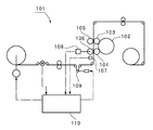
例えば、下記の特許文献1には、図7に示す印刷装置が開示されている。ここでは、ギア駆動胴102に、該ギア駆動胴102により駆動される複数の印刷圧胴103,104が連結されている。そして、印刷圧胴103,104と対をなすように印刷版胴105,106が配置されている。
For example,
印刷版胴105,106と印刷圧胴103,104との間に、先に印刷が施された印刷物が供給され、追刷りが行われる。印刷物には、レジスタマークが先刷りに際し印刷されている。このレジスタマークを検出するレジスタマーク検出器107と、印刷版胴105,106の回転方向位置を検出する回転位置検出器108とが設けられている。また、印刷版胴105,106の上流には、長尺状の印刷物の長さ方向位置を変化させるためのコンペンセータローラ109が配置されている。
Between the
印刷装置101では、上記回転位置検出器108により検出された印刷版胴105,106の回転方向位置の検出値と、レジスタマーク検出器107により検出されたレジスタマークの位置とに基づいて、印刷版胴105,106の回転方向位置と、レジスタマークの印刷物上の長さ方向位置との相対的な差が制御部110により演算される。そして、この相対的な差が追刷りが正しく行われる値となるように、コンペンセータローラ109が制御される。
特許文献1に記載の方法では、長尺状の印刷物が搬送されつつ、追刷りが開始され、その段階で、制御部110により上述した相対的な差が所望の値となるようにコンペンセータローラ109の位置が制御されていた。従って、コンペンセータローラ109の位置を変化させて追刷りを正しく行うに先立ち、既に印刷版胴105,106により長尺状の印刷物表面に印刷が行われていた。すなわち、正しい位置関係で追刷りが行われる前に、前記位置関係を正しく設定するために、印刷物に印刷が行われざるを得なかった。そのため、正しい位置関係で追刷りが行われるまでの間の印刷が余分に必要であり、工程が煩雑となるだけでなく、印刷物が無駄に消費されざるを得なかった。
In the method described in
本発明の目的は、上述した従来技術の欠点を解消し、追刷りに際し、無駄な印刷を行うことなく、先に印刷されていた図形に対して正しい位置に印刷を行うことを可能とする追刷り印刷の位置合わせ方法及び追刷り印刷装置を提供することにある。 The object of the present invention is to eliminate the above-mentioned drawbacks of the prior art and to enable additional printing to be performed at the correct position with respect to the previously printed figure without performing unnecessary printing at the time of reprinting. An object of the present invention is to provide a printing printing alignment method and a reprint printing apparatus.
本発明は、先に印刷が施された長尺状の印刷物を、外周面に印刷用凹部が設けられたグラビアロールと、該グラビアロールに印刷物を介して圧接される圧接ロールとの間に供給して追刷りを行うに際しての位置合わせ方法であって、前記圧接ロールが前記グラビアロール側に前記長尺状の印刷物を介して圧接される直前まで、前記圧接ロールを前記グラビアロールから隔て、前記印刷物をグラビアロールの外周面から隔てた状態で前記印刷物の長さ方向位置を検出する工程と、前記長さ方向位置を検出した時点におけるグラビアロールの回転方向位置を検出する工程と、前記印刷物に正しく追刷りが行われる際の前記長さ方向位置とグラビアロール回転方向位置との関係を元に、前記グラビアロールの回転方向位置を補正する補正工程と、前記補正工程に続いて、追刷りを開始する工程とを備えることを特徴とする。 The present invention supplies a long printed material that has been previously printed between a gravure roll having a concave portion for printing on the outer peripheral surface and a pressure contact roll that is pressed against the gravure roll via the printed material. In the repositioning method, the press roll is separated from the gravure roll until immediately before the press roll is pressed to the gravure roll side through the elongated printed matter, A step of detecting a length direction position of the printed matter in a state in which the printed matter is separated from an outer peripheral surface of the gravure roll; a step of detecting a rotational direction position of the gravure roll at the time of detecting the length direction position; A correction step of correcting the rotational direction position of the gravure roll based on the relationship between the longitudinal direction position and the gravure roll rotational direction position when the overprinting is correctly performed; Following correction step, characterized by comprising the step of initiating the add printing.
本発明に係る追刷り印刷の位置合わせ方法のある特定の局面では、前記補正工程において前記グラビアロールの回転方向位置の補正を行う際の前記長尺状の印刷物のパスラインと、前記追刷り印刷時の前記長尺状の印刷物のパスラインとが異なることを考慮して、前記グラビアロールの回転方向位置の補正が行われる。 In a specific aspect of the registration method of the overprint printing according to the present invention, the pass line of the elongated printed material when the rotational direction position of the gravure roll is corrected in the correction step, and the overprint printing In consideration of the fact that the pass line of the long printed material at the time is different, the rotation direction position of the gravure roll is corrected.
本発明に係る追刷り印刷の位置合わせ方法の他の特定の局面では、前記長尺状の印刷物がその長さ方向に搬送されつつ位置合わせが行われる。 In another specific aspect of the position alignment method for reprint printing according to the present invention, alignment is performed while the long printed material is conveyed in the length direction.
本発明に係る追刷り印刷の位置合わせ方法のさらに他の特定の局面では、前記追刷りに先立ち位置合わせが行われる各工程における長尺状の印刷物の搬送速度が、追刷り印刷に際しての搬送速度よりも遅くされる。 In still another specific aspect of the registration method for reprint printing according to the present invention, the transport speed of the long printed material in each step in which the positioning is performed prior to the reprint printing is the transport speed for the reprint printing. Will be slower than.
本発明に係る追刷り印刷の位置合わせ方法のさらに別の特定の局面では、前記追刷り印刷に際しての位置合わせを行うための各工程が、長尺状の印刷物を停止した状態で行われる。 In still another specific aspect of the registration method of the additional printing according to the present invention, each step for performing the registration in the additional printing is performed in a state where the long printed material is stopped.
本発明に係る追刷り印刷装置は、外周面に印刷用凹部が設けられたグラビアロールと、前記グラビアロールの外周面に前記印刷物を圧接する圧接ロールと、前記印刷物を長さ方向に搬送する搬送手段と、前記圧接ロールを前記グラビアロールから隔てた第1の状態と、追刷り印刷に際して前記圧接ロールを前記印刷物を介してグラビアロールの外周面に圧接させた第2の状態とを取り得るように、前記圧接ロール及び/またはグラビアロールの位置を変化させる位置変化手段と、前記印刷物の長さ方向位置を検出する第1の検出手段と、前記印刷物の長さ方向位置に対するグラビアロールの回転方向位置を検出する第2の検出手段と、検出された印刷物の長さ方向位置及びグラビアロールの回転方向位置と、正しく追刷り印刷が行われる際の印刷物の長さ方向位置とグラビアロールの回転方向位置との予め求められた関係に基づき、グラビアロールの回転方向位置を補正する制御手段とを備える。 The reprint printing apparatus according to the present invention includes a gravure roll having a printing recess on an outer peripheral surface, a pressure contact roll that presses the printed material against the outer peripheral surface of the gravure roll, and a transport that transports the printed material in a length direction. And a first state in which the pressure contact roll is separated from the gravure roll, and a second state in which the pressure contact roll is in pressure contact with the outer peripheral surface of the gravure roll through the printed matter during overprint printing. In addition, position changing means for changing the position of the pressure contact roll and / or gravure roll, first detection means for detecting the length direction position of the printed matter, and the rotation direction of the gravure roll with respect to the lengthwise position of the printed matter The second detection means for detecting the position, the detected position in the length direction of the printed matter and the rotational direction position of the gravure roll, and when the overprint printing is performed correctly Based on the previously obtained relationship between the length direction position and the rotational position of the gravure roll Surimono, and a control means for correcting the rotational position of the gravure roll.
本発明に係る追刷り印刷の位置合わせ方法では、圧接ロールがグラビアロール側に長尺状の印刷物を介して圧接される直前まで、圧接ロールをグラビアロールから隔てた状態、すなわち印刷物をグラビアロールの外周面から隔てた状態で印刷物の追刷りに際しての長さ方向位置が検出され、該長さ方向位置を検出した時点におけるグラビアロールの回転方向位置が検出され、正しく追刷りが行われる際の上記長さ方向位置と回転方向位置の関係を元に、グラビアロールの回転方向位置が補正される。従って、補正工程に続いて追刷りを開始することにより、正確に追刷りを行うことができる。 In the position alignment method for reprint printing according to the present invention, the state in which the pressure contact roll is separated from the gravure roll until immediately before the pressure contact roll is pressed to the gravure roll side through the elongated printed material, that is, the printed material is separated from the gravure roll. The position in the length direction at the time of reprinting the printed matter in a state separated from the outer peripheral surface is detected, the position in the rotation direction of the gravure roll at the time when the position in the length direction is detected, and the above when the reprint is performed correctly Based on the relationship between the length direction position and the rotation direction position, the rotation direction position of the gravure roll is corrected. Therefore, the additional printing can be accurately performed by starting the additional printing following the correction step.
しかも、上記のように、位置合わせに際しては、印刷物がグラビアロールに圧接されず、従って、試し刷りは行われない。よって、試し刷りを行うことなく、追刷りに際しての位置合わせを行うことができるので、印刷材料の節約を図り得るだけでなく、印刷作業の簡略化を果たすことができる。 In addition, as described above, the printed material is not pressed against the gravure roll at the time of alignment, and therefore no trial printing is performed. Therefore, since it is possible to perform alignment at the time of additional printing without performing trial printing, not only can the printing material be saved, but also the printing operation can be simplified.
また、従来の追刷りの位置合わせ方法では、試し刷りを行った後、一旦印刷装置を停止し、補正作業を行っていた。従って、従来の位置合わせ方法では、印刷工程の自動化を図るのが困難であったのに対し、本発明の追刷り印刷の位置合わせ方法では、装置を一旦停止する必要がないため、印刷工程の自動化を図ることも容易となる。 Further, in the conventional alignment method for additional printing, after performing the trial printing, the printing apparatus is temporarily stopped and the correction work is performed. Therefore, in the conventional alignment method, it is difficult to automate the printing process, whereas in the reprint printing alignment method of the present invention, it is not necessary to temporarily stop the apparatus. It is also easy to automate.
補正工程において、グラビアロールの回転方向位置の補正を行う際の長尺状の印刷物のパスラインと、追刷り印刷時の長尺状の印刷物のパスラインとが異なることを考慮して、グラビアロールの回転方向位置の補正が行われる場合には、追刷り印刷の位置合わせをより高精度に行うことができる。 In consideration of the fact that in the correction process, the pass line of the long printed material when correcting the rotational direction position of the gravure roll is different from the pass line of the long printed material at the time of reprint printing, When the rotation direction position is corrected, the position of the additional printing can be adjusted with higher accuracy.
長尺状の印刷物を長さ方向に搬送しつつ位置合わせを行う場合には、印刷物の搬送を停止する必要がないため、追刷り印刷工程の作業性を高めることができる。 When alignment is performed while a long printed material is conveyed in the length direction, it is not necessary to stop the conveyance of the printed material, so that the workability of the reprint printing process can be improved.
追刷りに先立ち、位置合わせを行うための各工程における長尺状の印刷物の搬送速度が、追刷り印刷に際しての搬送速度よりも遅くされている場合には、印刷物等の材料消費量の低減を図ることができる。 Prior to reprinting, if the conveyance speed of the long printed material in each process for alignment is slower than the conveyance speed for reprint printing, the consumption of materials such as printed material can be reduced. Can be planned.
追刷り印刷に際しての位置合わせを行うための各工程が、長尺状の印刷部を停止した状態で行われる場合には、印刷物の長さ方向位置の検出をより高精度に行うことができる。 In the case where each process for performing alignment in reprint printing is performed in a state where the long printing unit is stopped, the position in the length direction of the printed matter can be detected with higher accuracy.
本発明に係る追刷り印刷装置では、圧接ロール及び/またはグラビアロールの位置を変化させる位置変化手段により、圧接ロールがグラビアロールから隔てられた第1の状態と、追刷り印刷に際して、圧接ロールを印刷物を介してグラビアロールの外周面に圧接させる第2の状態とを取り得るように圧接ロール及び/またはグラビアロールが移動される。従って、第1の状態において、第1の検出手段により印刷物の長さ方向位置を検出し、第2の検出手段によりグラビアロールの回転方向位置を検出することにより、予め求められていた、正しく追刷りが行われる際の印刷物の長さ方向位置とグラビアロールの回転方向位置との関係に基づき、グラビアロールの回転方向位置を制御手段により補正することにより、試し刷りを行うことなく、追刷りに際しての位置合わせを本発明の位置合わせ方法に従って行うことができる。 In the reprint printing apparatus according to the present invention, in the first state in which the pressure contact roll is separated from the gravure roll by the position changing means for changing the position of the pressure contact roll and / or the gravure roll, The pressure contact roll and / or the gravure roll are moved so as to be able to take the second state of being pressed against the outer peripheral surface of the gravure roll via the printed matter. Therefore, in the first state, the first detection means detects the position in the length direction of the printed material, and the second detection means detects the rotation direction position of the gravure roll, thereby correctly adding the previously obtained information. Based on the relationship between the position in the length direction of the printed material and the rotation direction position of the gravure roll when printing is performed, the rotation direction position of the gravure roll is corrected by the control means, so that it is possible to perform additional printing without performing trial printing. Can be performed according to the alignment method of the present invention.
以下、図面を参照しつつ、本発明の具体的な実施形態を説明することにより、本発明を明らかにする。 Hereinafter, the present invention will be clarified by describing specific embodiments of the present invention with reference to the drawings.
(第1の実施形態)
図1〜図3を参照して、本発明の第1の実施形態に係る追刷り印刷の初期位置合わせ方法を説明する。
(First embodiment)
With reference to FIGS. 1 to 3, an initial alignment method for reprint printing according to the first embodiment of the present invention will be described.
図3は、本実施形態で用いられる追刷り印刷装置の概略構成図である。追刷り印刷装置1では、供給リール2が備えられている。供給リール2には、先に印刷が施された長尺状の印刷物が巻回されている。この長尺状の印刷物3が、供給リール2から巻取りリール4側に向かって搬送装置5により搬送される。搬送装置5としては、巻取りリール4を回転駆動するためのモータなどの適宜の駆動源を用いることができる。
FIG. 3 is a schematic configuration diagram of a reprint printing apparatus used in the present embodiment. In the
供給リール2の下流には、ローラ6a,6bとコンペンセータローラ7とが配置されている。コンペンセータローラ7の位置を図3の矢印X方向及び−X方向に移動させることにより、長尺状の印刷物3の長さ方向位置を補正することができる。すなわち、コンペンセータローラ7は、長尺状の印刷物3のパスラインの長さを調節し得るように、その位置が変化され得るように構成されている。コンペンセータローラ7をX方向または−X方向に移動させる装置としては、エアシリンダーや油圧シリンダーなどの往復駆動源、あるいは回転駆動源とラック及びピニョンを連結した機構などを挙げることができる。
コンペンセータローラ7の下流には、グラビアロール8及び圧接ロール9が配置されている。圧接ロール9は、印刷物3をグラビアロール8の外周面に圧接させ、グラビアロール8の外周面に設けられた印刷用凹部に応じた印刷を施し得るように構成されている。
A
また、圧接ロール9は、グラビアロール8の外周面から印刷物3が隔てられた第1の状態と、グラビアロール8に印刷物3を圧接させた第2の状態とをとり得るように、その位置が変化され得る。本実施形態では、圧接ロールが第1の状態と第2の状態とをとり得るように、圧接ロールの位置が変化されているが、グラビアロール8の位置が変化されてもよく、あるいは圧接ロール9及びグラビアロール8の双方の位置が変化されて、第1,第2の状態が実現されてもよい。
Further, the position of the
グラビアロール8の下流には、トリガマーク検出センサー10及びカメラ11が配置されている。トリガマーク検出センサー10は、印刷物3に印刷された後述のトリガマークを検出するために設けられている。トリガマーク検出センサー10は、光学式センサーなどの適宜の検出手段により構成される。トリガマーク検出センサー10は、本発明の第1の検出手段を構成しており、上記印刷物の長さ方向位置を検出するために設けられている。
A trigger
また、カメラ11は、グラビアロール8の回転方向位置を検出するために設けられている。従って、カメラ11は、本発明の位置合わせ方法における第2の検出手段を構成している。もっとも、グラビアロール8の回転方向位置を検出し得る限り、第2の検出手段はカメラ以外の他の検出手段により構成されていてもよい。
The
カメラ11の下流には、乾燥炉12が配置されている。乾燥炉12は、印刷された図形を乾燥するために設けられている。
A drying
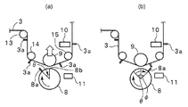
図3では略図的に示されているが、図1(a)に示すように、グラビアロール8及び圧接ロール9の上流側及び下流側には、それぞれ、ロール13,14と、ロール15とが配置されている。図1(a)は、圧接ロール9が第1の状態にある場合を示している。第1の状態とは、図1(a)に示すように、圧接ロール9がグラビアロール8から隔てられており、言い換えれば、長尺状の印刷物3がグラビアロール8の外周面に接触していない状態をいうものとする。また、圧接ロール9が第2の状態にある場合とは、印刷に際し、圧接ロール9により印刷物3がグラビアロール8の外周面に圧接されている状態をいうものとする。
Although schematically shown in FIG. 3, as shown in FIG. 1A, on the upstream side and downstream side of the
また、本実施形態のスクリーン印刷に際しての初期位置合わせを行うために、制御装置19が設けられている。制御装置19は、搬送装置5、トリガマーク検出センサー10及びカメラ11に電気的に接続されている。制御装置19は、搬送装置5による印刷物3の搬送を開始もしくは停止信号を搬送装置5に与えたり、搬送速度を変化させる電気信号を搬送装置5に与える。また、制御装置19には、トリガマーク検出センサー10により検出された印刷物3の長さ方向位置、及びカメラ11により検出されたグラビアロール8の回転方向位置が与えられる。制御装置19には、予め、正しく追刷りが行われる際の印刷物3の長さ方向位置と、グラビアロール8の回転方向位置との位置関係が記憶されている。
In addition, a
追刷り印刷装置1を用いた印刷方法及び印刷に際しての初期位置合わせ方法を、図1〜図3を参照して説明する。
A printing method using the
本実施形態では、追刷りに際しての初期位置合わせは、圧接ロール9を第1の状態に位置させて行われる。すなわち、印刷物3がグラビアロール8に接触されず、すなわち試し刷りが行われずに、初期位置合わせが行われる。
In the present embodiment, the initial positioning at the time of reprinting is performed with the
印刷物3には、追刷りに先立って行われた印刷、すなわち先刷りにおいて、位置合わせ用トリガマーク3aが印刷されている。図1(a)では、トリガマーク3aの位置を明瞭にするために、あたかもトリガマーク3aが印刷物3から突出しているように図示されている。図2(a)に示すように、先刷りにおいて印刷された印刷図形が矩形の枠状の印刷図形16であるとする。そして、グラビアロール8を用いて追刷りにより印刷される図形が円形の印刷図形17であるとする。図2(a)は、追刷り印刷に際しての位置合わせが不十分な場合の追刷り印刷の仮想的な結果を示す印刷物の部分切欠平面図である。図2(a)に示すように、追刷りによる円形の印刷図形17が矩形の印刷図形16の中心からずれて配置されている。
The printed
他方、図2(b)は、先刷りで印刷された印刷図形16の中心に、追刷りで印刷された印刷図形17が位置している場合を示す部分切欠平面図である。図2(b)では、追刷りが、正確に行われ、従って印刷図形17の中心が印刷図形16の中心と合致されている。すなわち、図2(b)に示されているように追刷りを行うことが必要である。 On the other hand, FIG. 2B is a partially cutaway plan view showing a case where the printed graphic 17 printed by the additional printing is located at the center of the printed graphic 16 printed by the preprinting. In FIG. 2B, the reprinting is performed accurately, so that the center of the printed figure 17 coincides with the center of the printed figure 16. That is, it is necessary to perform reprinting as shown in FIG.
他方、先刷りに際しては、印刷図形16だけでなく、トリガマーク3aが印刷物3の表面に印刷されている。トリガマーク3aは、印刷図形16と所定の位置関係を有するように先刷りに際して印刷されている。そして、トリガマーク3aがトリガマーク検出センサー10により検出され、搬送されている印刷物3の長さ方向位置が検出される。
On the other hand, not only the printed figure 16 but also the trigger mark 3a is printed on the surface of the printed
図1(a),(b)に示すように、グラビアロール8の外周面には、トリガマーク8aが設けられている。このトリガマーク8aは、グラビアロール8の外表面に設けられた凹部などの適宜の構造で構成することができる。
As shown in FIGS. 1A and 1B, a trigger mark 8 a is provided on the outer peripheral surface of the
初期位置合わせに際しては、図1(a)に示した状態で、グラビアロール8が矢印方向に回転され、その際のトリガマーク8aの位置がカメラ11により検出される。従って、グラビアロール8の回転方向位置が、トリガマーク8aを検出することにより確認される。
In the initial alignment, the
そして、図3に示した制御手段19には、カメラ11から与えられたグラビアロール8の回転方向位置と、印刷物3上のトリガマーク3aの検出により得られた印刷物3の長さ方向位置とを与えられる。他方、予め、制御装置19には、追刷りが正確に行われる際、すなわち図2(b)に示したように印刷が行われる場合のグラビアロールの回転方向位置と、印刷物3の長さ方向位置との位置関が記憶されている。具体的には、正確に追刷りが行われる際のトリガマーク8a、トリガマーク3aとの位置関係がグラビアロール8の回転角度差として記憶されている。
Then, in the control means 19 shown in FIG. 3, the rotation direction position of the
図1(b)は、このように、追刷りが正確に行われる際のトリガマーク8aと、トリガマーク3aとの関係を示す。このような位置関係にある時、図2(b)に示すように、追刷り後に、印刷物3上において、トリガマーク3a上に正確にトリガマーク8aによる印刷図形が重なる。従って、図2(b)に示すように、トリガマーク3a上に、トリガマーク8aによる印刷図形が重なることになる。
FIG. 1B shows the relationship between the trigger mark 8a and the trigger mark 3a when the overprinting is accurately performed as described above. In such a positional relationship, as shown in FIG. 2B, the printed figure by the trigger mark 8a accurately overlaps the trigger mark 3a on the printed
いま、図1(a)に示すように、グラビアロールのトリガマーク8aが、印刷物3に接触される頂点8bと中心とを結ぶ線から−θの中心角をなす外周面部分に位置しているとする。この場合,図2(a)に示したように、先刷りで印刷されたトリガマーク3aと、追刷りで印刷されるトリガマーク8aの印刷図形8Aとが分離することになる。なお、図2(a)は、追刷りが正確でなかった場合の結果を示す部分切欠平面図であり、本実施形態では、前述したように、追刷りに際しての初期位置合わせは試し刷りを行わないため、現実には図2(a)に示されている印刷結果は生じないことを指摘しておく。
Now, as shown in FIG. 1A, the gravure roll trigger mark 8a is positioned on the outer peripheral surface portion forming a central angle of −θ from the line connecting the
ところで、図1(b)に示す状態、すなわちトリガマーク3aとトリガマーク8aとが正しい位置関係にある場合には、グラビアロール8のトリガマーク8aの回転方向位置を示す角度が、グラビアロール8の頂点8bと中心とを結ぶ線から中心角で+φであるとする。そうすると、本実施形態では、グラビアロール8の回転方向位置は、φ−θだけ移動される。
By the way, in the state shown in FIG. 1B, that is, when the trigger mark 3 a and the trigger mark 8 a are in the correct positional relationship, the angle indicating the rotational direction position of the trigger mark 8 a of the
すなわち、上記のように、φ−θだけグラビアロール8の回転方向位置を移動させれば、図1(b)に示したように、追刷りに際してのグラビアロール8の回転方向位置と、印刷物3の長さ方向位置とを正確に合致させることができ、図2(b)に示したように印刷図形16の中心に印刷図形17を正確に合致させることができる。
That is, as described above, if the rotational direction position of the
なお、上記グラビアロール8の回転方向位置を補正することにより位置ずれを補正するに際し、上記印刷物3は搬送されている必要は必ずしもなく、停止されていてもよい。また、印刷物3を搬送しつつ、上記初期位置合わせを行ってもよい。いずれにしても、初期位置合わせに際しては、圧接ロール9が前述した第1の状態とされており、従って試し刷りは行われない。よって、印刷物3において、追刷りに際しての印刷図形が適切ではない位置に印刷された不要な印刷物の発生を防止することができるとともに、印刷材料の節約を図ることができる。
Note that when the positional deviation is corrected by correcting the rotational direction position of the
なお、本実施形態の初期位置合わせでは、印刷物3がグラビアロール8の外周面に圧接されていない状態で位置合わせが行われる。従って、上記位置合わせが行われた後に、圧接ロール9の第2の状態とし、印刷物3をグラビアロール8の外周面に圧接させて印刷を行う。そのため、上記φ−θの角度を補正するだけでなく、圧接ロール9を第1の状態から第2の状態とした時に印刷物3の長さ方向位置がずれることになるため、このずれ量を補正することが望ましい。すなわち、圧接ロール9が第1の状態にある場合の印刷物のパスラインと、第2の状態にある場合の印刷物のパスラインとがずれることになるため、上記ずれ量を補正することが望ましい。この印刷物3の長さ方向のずれ量については、予め容易に求めることかでき、かつ前述したコンペンセータローラ7の位置を制御することにより容易に補正することができる。
In the initial alignment of the present embodiment, alignment is performed in a state where the printed
(第2の実施形態)
図4は、本発明の第2の実施形態に係る追刷り印刷装置の概略構成図である。本実施形態の追刷り印刷装置21は、積層セラミックコンデンサの製造に際し、セラミックグリーンシート上に内部電極パターンを形成するための導電ペースト及び段差解消用セラミックペーストを印刷するのに用いられる。より具体的には、長尺状のキャリアフィルムに支持された長尺状のグリーンシート上に、内部電極パターン及び段差解消用セラミックペーストがまず印刷され、複合シートが得られる。そして、この複合シートの上面に、さらにセラミックペースト層が全面に形成される。しかる後、2層目の内部電極パターン及び段差解消用セラミックペーストが印刷される。このような製造方法において、上記2層目の内部電極パターン及び段差解消用セラミックペーストの印刷に本実施形態の追刷り印刷装置21が用いられる。
(Second Embodiment)
FIG. 4 is a schematic configuration diagram of a reprint printing apparatus according to the second embodiment of the present invention. The
追刷り印刷装置21は、供給リール22を有する。供給リール22から、上述したセラミックペースト層が全面に形成されて複合シートが印刷物23として供給される。この印刷物23では、長尺状のキャリアフィルム上にセラミックグリーンシートが形成されており、かつ該セラミックグリーンシートの上面に、導電ペーストからなる内部電極パターン及び段差解消用セラミックペーストが印刷されて、複合シートが構成されている。さらにこの複合シートの上面に、セラミックペースト層が全面に形成されている。この全面に形成されたセラミックペースト層は、印刷により形成されてもよく、あるいは別途成形されたセラミックグリーンシートを複合シートの上面に熱圧着することにより形成されていてもよい。
The
本実施形態の追刷り印刷装置21は、第1,第2の印刷装置21A,21Bを直列に接続した二色刷り印刷装置である。
The
そして、第1,第2の印刷装置21A,21Bは、第1の実施形態について示した図3の追刷り印刷装置1とほぼ同様に構成されている。従って、第1,第2の印刷装置21A,21Bの各部分の参照番号については、それぞれ、図3に示した追刷り印刷装置1における各部分の参照番号に、20及び40を加えた番号を付することにより、個々の相当する部分についての詳細な説明は省略することとする。
The first and
なお、制御装置については、第1,第2の印刷装置21A,21Bにおいて、通過されており、従って、制御装置39は、第1の印刷装置21Aだけでなく、第2の印刷装置21Bにも接続されている。
Note that the control device passes through the first and
本実施形態では、上記追刷り印刷装置21Aにおいて、まず導電ペーストが印刷され、2層目の内部電極パターンが印刷され、第2の追刷り印刷装置21Bにおいて2層目の段差解消用セラミックペースト層が印刷され、巻取りリール24により巻き取られる。
In the present embodiment, in the
そして、上記印刷装置21A,21Bのいずれにおいても、本発明に従って追刷りに際しての初期位置合わせが行われる。これをより具体的に説明する。
In either of the
まず、第1,第2の印刷装置21A,21Bにおいて、圧接ロール29,49が第1の状態とされ、その状態で印刷物23が搬送される。この時の搬送速度は、材料の消費量を低減するために、通常の印刷時の速度よりも低速で行うことが望ましく、10m/分程度が望ましい。
First, in the first and
次に、印刷物23を搬送している間に、印刷物23に予め印刷されているトリガマークをトリガマーク検出センサー30,50でそれぞれ検出する。このトリガマークは、先刷りに際して、上記複合シートに印刷されたトリガマーク、あるいは複合シート上に付与されたセラミックペースト層の上面に設けられたトリガマークである。なお、複合シートの上面に直接トリガマークが設けられている場合であっても、該複合シート上に設けられたセラミックペースト層の厚みが薄い場合には、該セラミックペースト層を透かして複合シート上のトリガマークをトリガマーク検出センサー30,50で検出することができる。
Next, while the printed
次に、各トリガマーク検出センサー30,50でトリガマークが検出された際の第1の印刷装置21Aのグラビアロール28の回転方向位置及び第2の印刷装置21Bにおけるグラビアロール48の回転方向位置を第2の検出手段としてのカメラ31,51を用いて検出する。このようにして、グラビアロール28,48の回転方向位置の検出値が、角度θ1,θ2として得られる。この角度θ1,θ2は、図1(a)に示した角度θに相当する。
Next, the rotational direction position of the
他方、制御装置39には、予め、印刷物23の長さ方向位置と、グラビアロール28,48の回転方向位置とが合致している際にトリガマークが検出される際のグラビアロール28,48の回転方向位置である角度φ1,φ2が記憶されている。この角度φ1,φ2は、第1の実施形態における角度φに相当する。
On the other hand, in the
従って、本実施形態においても、グラビアロール28,48を、それぞれ、角度φ1−θ1及びφ2−θ2だけ移動させることにより、第1の実施形態の場合と同様に、印刷物23に正確に印刷装置21A,21Bにおいて追刷りを行うことができる。もっとも、本実施形態においても、上記初期位置合わせは、圧接ロール29,49が第1の状態で行われるため、第2の状態に移動した際の印刷物23の長さ方向ずれをさらにコンペンセータローラ27,47を用いて補正する必要がある。
Therefore, also in the present embodiment, the gravure rolls 28 and 48 are moved by the angles φ1 to θ1 and φ2 to θ2, respectively, so that the
このようにして、印刷物23に二色刷りの追刷りを行う際の初期位置合わせが行われる。本実施形態においても、上記初期位置合わせは、試し刷りを行わずに行うことが可能とされている。
In this way, initial alignment when performing two-color reprinting on the printed
そして、追刷りに際しては、圧接ロール29,49を第2の状態とし、通常の印刷速度で印刷物23を搬送し、追刷りを行えばよい。
When reprinting, the press rolls 29 and 49 are set in the second state, the printed
本実施形態では、このようにして、2層目の内部電極パターン及び段差解消用セラミックペーストが印刷され、巻取りリール24において、印刷物23が巻き取られる。このようにして得られた2層の誘電体素子部分を有する印刷物23を、キャリアフィルムから剥離し、さらに複数枚積層する。このようにして積層体が得られる。そして、得られた積層体を厚み方向に加圧し、切断することにより、図5に示す積層体61が得られる。得られた積層体61を焼成し、得られた焼結体に外部電極を形成することにより、図6に示す積層セラミックコンデンサが得られる。図6において、積層セラミックコンデンサ62は、セラミック焼結体63と、セラミック焼結体63の外表面に形成された外部電極64,65とを有する。また、セラミック焼結体63内には、複数の内部電極66が形成されている。
In the present embodiment, the second-layer internal electrode pattern and the step-resolving ceramic paste are printed in this way, and the printed
なお、本発明に係る追刷り印刷方法は、上記のような電子部品の製造方法に好適に用いられるが、グラビアロールを用いたその他の用途における追刷り印刷に広く用いることができる。 The reprint printing method according to the present invention is preferably used for the above-described electronic component manufacturing method, but can be widely used for reprint printing in other applications using a gravure roll.
1…追刷り印刷装置
2…供給リール
3…印刷物
3a…トリガマーク
4…巻取りリール
5…搬送装置
6a,6b…ローラ
7…コンペンセータローラ
8…グラビアロール
8a…トリガマーク
8A…トリガマーク印刷図形
9…圧接ロール
10…トリガマーク検出センサー
11…カメラ
12…乾燥炉
13〜15…ロール
16…印刷図形
17…印刷図形
21…追刷り印刷装置
22…供給リール
23…印刷物
24…巻取りリール
25,26…ロール
27…コンペンセータローラ
28…グラビアロール
29…圧接ロール
30…トリガマーク検出センサー
31…カメラ
32…乾燥炉
45,46…ロール
47…コンペンセータローラ
48…グラビアロール
49…圧接ロール
50…トリガマーク検出センサー
51…カメラ
52…乾燥炉
61…積層体
62…積層セラミックコンデンサ
63…焼結体
64,65…外部電極
66…内部電極
DESCRIPTION OF
Claims (6)
前記圧接ロールが前記グラビアロール側に前記長尺状の印刷物を介して圧接される直前まで、前記圧接ロールを前記グラビアロールから隔て、前記印刷物をグラビアロールの外周面から隔てた状態で前記印刷物の長さ方向位置を検出する工程と、
前記長さ方向位置を検出した時点におけるグラビアロールの回転方向位置を検出する工程と、
前記印刷物に正しく追刷りが行われる際の前記長さ方向位置とグラビアロール回転方向位置との関係を元に、前記グラビアロールの回転方向位置を補正する補正工程と、
前記補正工程に続いて、追刷りを開始する工程とを備えることを特徴とする、追刷り印刷の位置合わせ方法。 A long printed matter that has been printed first is supplied between a gravure roll having a printing recess on the outer peripheral surface and a pressure contact roll that is pressed against the gravure roll via the printed matter, and reprinted. A positioning method when performing
The press contact roll is separated from the gravure roll and the print product is separated from the outer peripheral surface of the gravure roll until immediately before the press contact roll is press-contacted to the gravure roll side via the elongated printed product. Detecting the longitudinal position;
Detecting the rotational direction position of the gravure roll at the time of detecting the length direction position;
A correction step of correcting the rotational direction position of the gravure roll based on the relationship between the position in the length direction and the rotational direction position of the gravure roll when the printed matter is correctly overprinted,
And a step of starting a supplementary printing subsequent to the correcting step.
外周面に印刷用凹部が設けられたグラビアロールと、
前記グラビアロールの外周面に前記印刷物を圧接する圧接ロールと、
前記印刷物を長さ方向に搬送する搬送手段と、
前記圧接ロールを前記グラビアロールから隔てた第1の状態と、追刷り印刷に際して前記圧接ロールを前記印刷物を介してグラビアロールの外周面に圧接させた第2の状態とを取り得るように、前記圧接ロール及び/またはグラビアロールの位置を変化させる位置変化手段と、
前記印刷物の長さ方向位置を検出する第1の検出手段と、
前記印刷物の長さ方向位置に対するグラビアロールの回転方向位置を検出する第2の検出手段と、
検出された印刷物の長さ方向位置及びグラビアロールの回転方向位置と、正しく追刷り印刷が行われる際の印刷物の長さ方向位置とグラビアロールの回転方向位置との予め求められた関係に基づき、グラビアロールの回転方向位置を補正する制御手段とを備える、追刷り印刷装置。
A reprint printing apparatus for performing reprinting while conveying a long printed material that has been previously printed in the length direction,
A gravure roll provided with a recess for printing on the outer peripheral surface;
A pressure roll that presses the printed matter against the outer peripheral surface of the gravure roll;
Conveying means for conveying the printed matter in the length direction;
The first state in which the pressure contact roll is separated from the gravure roll, and the second state in which the pressure contact roll is in pressure contact with the outer peripheral surface of the gravure roll through the printed matter at the time of reprint printing, can be taken. Position changing means for changing the position of the pressure contact roll and / or the gravure roll;
First detection means for detecting a longitudinal position of the printed matter;
Second detection means for detecting a rotational direction position of the gravure roll with respect to a longitudinal direction position of the printed matter;
Based on the previously determined relationship between the detected length direction position of the printed matter and the rotation direction position of the gravure roll, and the length direction position of the printed matter and the rotation direction position of the gravure roll when correct overprinting is performed correctly, A reprint printing apparatus comprising control means for correcting the rotational direction position of the gravure roll.
Priority Applications (1)
| Application Number | Priority Date | Filing Date | Title |
|---|---|---|---|
| JP2003372208A JP4675038B2 (en) | 2003-10-31 | 2003-10-31 | Electronic component manufacturing method and electronic component manufacturing apparatus |
Applications Claiming Priority (1)
| Application Number | Priority Date | Filing Date | Title |
|---|---|---|---|
| JP2003372208A JP4675038B2 (en) | 2003-10-31 | 2003-10-31 | Electronic component manufacturing method and electronic component manufacturing apparatus |
Publications (2)
| Publication Number | Publication Date |
|---|---|
| JP2005132017A true JP2005132017A (en) | 2005-05-26 |
| JP4675038B2 JP4675038B2 (en) | 2011-04-20 |
Family
ID=34648651
Family Applications (1)
| Application Number | Title | Priority Date | Filing Date |
|---|---|---|---|
| JP2003372208A Expired - Lifetime JP4675038B2 (en) | 2003-10-31 | 2003-10-31 | Electronic component manufacturing method and electronic component manufacturing apparatus |
Country Status (1)
| Country | Link |
|---|---|
| JP (1) | JP4675038B2 (en) |
Cited By (12)
| Publication number | Priority date | Publication date | Assignee | Title |
|---|---|---|---|---|
| JP2010017905A (en) * | 2008-07-09 | 2010-01-28 | Toppan Forms Co Ltd | Printing machine |
| CN103129103A (en) * | 2011-11-30 | 2013-06-05 | 三星电机株式会社 | Gravure printing apparatus |
| JP2016120632A (en) * | 2014-12-24 | 2016-07-07 | 株式会社小森コーポレーション | Printing method and apparatus for electronic circuit |
| JP2016120634A (en) * | 2014-12-24 | 2016-07-07 | 株式会社小森コーポレーション | Printing method and apparatus for electric circuit |
| JP2016120633A (en) * | 2014-12-24 | 2016-07-07 | 株式会社小森コーポレーション | Printing method and apparatus for electronic circuit |
| JP2016120639A (en) * | 2014-12-24 | 2016-07-07 | 株式会社小森コーポレーション | Printing method and apparatus for electronic circuit |
| JP2016122714A (en) * | 2014-12-24 | 2016-07-07 | 株式会社小森コーポレーション | Printing method and device of electronic circuit |
| JP2016120631A (en) * | 2014-12-24 | 2016-07-07 | 株式会社小森コーポレーション | Printing method and apparatus for electronic circuit |
| CN107107609A (en) * | 2014-12-24 | 2017-08-29 | 小森公司 | The printing process of electronic circuit and device |
| JP2017178544A (en) * | 2016-03-30 | 2017-10-05 | 大日本印刷株式会社 | Workpiece feeding device |
| JP2020116953A (en) * | 2020-03-31 | 2020-08-06 | 旭化成株式会社 | Flexible substrate |
| JP7458305B2 (en) | 2020-11-27 | 2024-03-29 | 住友重機械工業株式会社 | Printing device, printing method, printing program |
Citations (12)
| Publication number | Priority date | Publication date | Assignee | Title |
|---|---|---|---|---|
| JPH0298447A (en) * | 1988-10-05 | 1990-04-10 | Komori Printing Mach Co Ltd | Faulty follow-up print detection device |
| JPH02172745A (en) * | 1988-12-27 | 1990-07-04 | Toppan Printing Co Ltd | Registering method of gravure printing press |
| JPH039844A (en) * | 1989-06-06 | 1991-01-17 | Nippon Reliance Kk | Control system in multi-color printer |
| JPH05254106A (en) * | 1992-03-10 | 1993-10-05 | Nireco Corp | Rotary extra printing machine |
| JPH1016197A (en) * | 1996-07-03 | 1998-01-20 | Dainippon Printing Co Ltd | Path length correcting apparatus and photogravure press |
| JP2000309088A (en) * | 1999-04-27 | 2000-11-07 | Dainippon Printing Co Ltd | Method and device for controlling printing register |
| JP2002254595A (en) * | 2001-03-05 | 2002-09-11 | Miyakoshi Printing Machinery Co Ltd | Rotary press |
| JP2003249121A (en) * | 2001-12-20 | 2003-09-05 | Murata Mfg Co Ltd | Conductive paste and laminated ceramic electronic component |
| JP2003260860A (en) * | 2002-03-08 | 2003-09-16 | Murata Mfg Co Ltd | Method and device for manufacturing laminated ceramic electronic part and paste printing method |
| JP2003264118A (en) * | 2002-03-08 | 2003-09-19 | Murata Mfg Co Ltd | Multilayer ceramic electronic component |
| JP2003303737A (en) * | 1999-02-23 | 2003-10-24 | Murata Mfg Co Ltd | Manufacturing method of layered ceramic electronic component |
| JP2004262072A (en) * | 2003-02-28 | 2004-09-24 | Toshiba Mach Co Ltd | Overprinting adjusting method for rotary press |
-
2003
- 2003-10-31 JP JP2003372208A patent/JP4675038B2/en not_active Expired - Lifetime
Patent Citations (12)
| Publication number | Priority date | Publication date | Assignee | Title |
|---|---|---|---|---|
| JPH0298447A (en) * | 1988-10-05 | 1990-04-10 | Komori Printing Mach Co Ltd | Faulty follow-up print detection device |
| JPH02172745A (en) * | 1988-12-27 | 1990-07-04 | Toppan Printing Co Ltd | Registering method of gravure printing press |
| JPH039844A (en) * | 1989-06-06 | 1991-01-17 | Nippon Reliance Kk | Control system in multi-color printer |
| JPH05254106A (en) * | 1992-03-10 | 1993-10-05 | Nireco Corp | Rotary extra printing machine |
| JPH1016197A (en) * | 1996-07-03 | 1998-01-20 | Dainippon Printing Co Ltd | Path length correcting apparatus and photogravure press |
| JP2003303737A (en) * | 1999-02-23 | 2003-10-24 | Murata Mfg Co Ltd | Manufacturing method of layered ceramic electronic component |
| JP2000309088A (en) * | 1999-04-27 | 2000-11-07 | Dainippon Printing Co Ltd | Method and device for controlling printing register |
| JP2002254595A (en) * | 2001-03-05 | 2002-09-11 | Miyakoshi Printing Machinery Co Ltd | Rotary press |
| JP2003249121A (en) * | 2001-12-20 | 2003-09-05 | Murata Mfg Co Ltd | Conductive paste and laminated ceramic electronic component |
| JP2003260860A (en) * | 2002-03-08 | 2003-09-16 | Murata Mfg Co Ltd | Method and device for manufacturing laminated ceramic electronic part and paste printing method |
| JP2003264118A (en) * | 2002-03-08 | 2003-09-19 | Murata Mfg Co Ltd | Multilayer ceramic electronic component |
| JP2004262072A (en) * | 2003-02-28 | 2004-09-24 | Toshiba Mach Co Ltd | Overprinting adjusting method for rotary press |
Cited By (15)
| Publication number | Priority date | Publication date | Assignee | Title |
|---|---|---|---|---|
| JP2010017905A (en) * | 2008-07-09 | 2010-01-28 | Toppan Forms Co Ltd | Printing machine |
| CN103129103A (en) * | 2011-11-30 | 2013-06-05 | 三星电机株式会社 | Gravure printing apparatus |
| JP2013111973A (en) * | 2011-11-30 | 2013-06-10 | Samsung Electro-Mechanics Co Ltd | Gravure printing apparatus |
| JP2016120639A (en) * | 2014-12-24 | 2016-07-07 | 株式会社小森コーポレーション | Printing method and apparatus for electronic circuit |
| JP2016120634A (en) * | 2014-12-24 | 2016-07-07 | 株式会社小森コーポレーション | Printing method and apparatus for electric circuit |
| JP2016120633A (en) * | 2014-12-24 | 2016-07-07 | 株式会社小森コーポレーション | Printing method and apparatus for electronic circuit |
| JP2016120632A (en) * | 2014-12-24 | 2016-07-07 | 株式会社小森コーポレーション | Printing method and apparatus for electronic circuit |
| JP2016122714A (en) * | 2014-12-24 | 2016-07-07 | 株式会社小森コーポレーション | Printing method and device of electronic circuit |
| JP2016120631A (en) * | 2014-12-24 | 2016-07-07 | 株式会社小森コーポレーション | Printing method and apparatus for electronic circuit |
| CN107107609A (en) * | 2014-12-24 | 2017-08-29 | 小森公司 | The printing process of electronic circuit and device |
| CN107107609B (en) * | 2014-12-24 | 2019-03-29 | 小森公司 | The printing process of electronic circuit and device |
| JP2017178544A (en) * | 2016-03-30 | 2017-10-05 | 大日本印刷株式会社 | Workpiece feeding device |
| JP2020116953A (en) * | 2020-03-31 | 2020-08-06 | 旭化成株式会社 | Flexible substrate |
| JP6998417B2 (en) | 2020-03-31 | 2022-01-18 | 旭化成株式会社 | Flexible substrate |
| JP7458305B2 (en) | 2020-11-27 | 2024-03-29 | 住友重機械工業株式会社 | Printing device, printing method, printing program |
Also Published As
| Publication number | Publication date |
|---|---|
| JP4675038B2 (en) | 2011-04-20 |
Similar Documents
| Publication | Publication Date | Title |
|---|---|---|
| US7739950B2 (en) | Method for manufacturing ceramic electronic component and gravure printing method | |
| JP4675038B2 (en) | Electronic component manufacturing method and electronic component manufacturing apparatus | |
| US5048416A (en) | Multi-color printing apparatus | |
| WO2015190271A1 (en) | Printing machine and method for manufacturing printed matter | |
| JP4419370B2 (en) | Method for manufacturing multilayer ceramic electronic component and gravure printing method | |
| JP2019142232A (en) | Printing machine and printing method | |
| JP2003133167A (en) | Manufacturing method of laminated electronic parts | |
| JP6652328B2 (en) | Composite printing machine having gravure printing device and composite printing method for performing gravure printing as additional printing | |
| JP6554908B2 (en) | Printing machine and printing method | |
| JPH11277861A (en) | Stencil printing | |
| JP4078853B2 (en) | Manufacturing method and manufacturing apparatus for multilayer ceramic electronic component and paste printing method | |
| JP2005109296A (en) | Method of manufacturing laminated ceramic electronic component, and printing method using web press | |
| JP2017178544A (en) | Workpiece feeding device | |
| JP4543636B2 (en) | Manufacturing method of multilayer ceramic electronic component | |
| JP4508235B2 (en) | Method for manufacturing ceramic electronic component and gravure printing method | |
| JP2017121985A (en) | Work-piece supply device | |
| JP2007027605A (en) | Method for manufacturing stacked electronic component, and device thereof | |
| JP2011073414A (en) | Printing machine for printing on roll-formed object to be printed and method for printing using this machine | |
| JP2006237458A (en) | Manufacturing method of laminated electronic component and apparatus thereof | |
| JP3233678U (en) | Gravure printing equipment | |
| JP5243120B2 (en) | Printer | |
| JP2006187909A (en) | Gravure printing machine and gravure printing method | |
| JP2008016752A (en) | Manufacturing apparatus of laminated electronic component | |
| JP4046080B2 (en) | Laminate manufacturing equipment | |
| JP2006341560A (en) | Printer/drum unit |
Legal Events
| Date | Code | Title | Description |
|---|---|---|---|
| A621 | Written request for application examination |
Free format text: JAPANESE INTERMEDIATE CODE: A621 Effective date: 20060922 |
|
| A131 | Notification of reasons for refusal |
Free format text: JAPANESE INTERMEDIATE CODE: A131 Effective date: 20090609 |
|
| A521 | Request for written amendment filed |
Free format text: JAPANESE INTERMEDIATE CODE: A523 Effective date: 20090729 |
|
| A02 | Decision of refusal |
Free format text: JAPANESE INTERMEDIATE CODE: A02 Effective date: 20090915 |
|
| A521 | Request for written amendment filed |
Free format text: JAPANESE INTERMEDIATE CODE: A523 Effective date: 20091214 |
|
| A911 | Transfer to examiner for re-examination before appeal (zenchi) |
Free format text: JAPANESE INTERMEDIATE CODE: A911 Effective date: 20091225 |
|
| A912 | Re-examination (zenchi) completed and case transferred to appeal board |
Free format text: JAPANESE INTERMEDIATE CODE: A912 Effective date: 20100402 |
|
| A521 | Request for written amendment filed |
Free format text: JAPANESE INTERMEDIATE CODE: A523 Effective date: 20101224 |
|
| A01 | Written decision to grant a patent or to grant a registration (utility model) |
Free format text: JAPANESE INTERMEDIATE CODE: A01 |
|
| A61 | First payment of annual fees (during grant procedure) |
Free format text: JAPANESE INTERMEDIATE CODE: A61 Effective date: 20110125 |
|
| FPAY | Renewal fee payment (event date is renewal date of database) |
Free format text: PAYMENT UNTIL: 20140204 Year of fee payment: 3 |
|
| R150 | Certificate of patent or registration of utility model |
Ref document number: 4675038 Country of ref document: JP Free format text: JAPANESE INTERMEDIATE CODE: R150 Free format text: JAPANESE INTERMEDIATE CODE: R150 |
|
| EXPY | Cancellation because of completion of term |