JP2005125627A - Method for forming surface protecting layer with smooth surface - Google Patents
Method for forming surface protecting layer with smooth surface Download PDFInfo
- Publication number
- JP2005125627A JP2005125627A JP2003364193A JP2003364193A JP2005125627A JP 2005125627 A JP2005125627 A JP 2005125627A JP 2003364193 A JP2003364193 A JP 2003364193A JP 2003364193 A JP2003364193 A JP 2003364193A JP 2005125627 A JP2005125627 A JP 2005125627A
- Authority
- JP
- Japan
- Prior art keywords
- protective layer
- layer
- surface protective
- thermoplastic resin
- roughness
- Prior art date
- Legal status (The legal status is an assumption and is not a legal conclusion. Google has not performed a legal analysis and makes no representation as to the accuracy of the status listed.)
- Pending
Links
Images

Landscapes
- Surface Treatment Of Optical Elements (AREA)
- Application Of Or Painting With Fluid Materials (AREA)
- Shaping Of Tube Ends By Bending Or Straightening (AREA)
Abstract
Description
本発明は、熱可塑性樹脂フィルム又は熱可塑性樹脂成形体等の表面に、表面硬度や耐摩耗性の向上を目的とした透明な硬化型樹脂からなる表面保護層を形成するに際し、該表面保護層の表面を鏡面状等の平滑面としても、その表裏面での反射光の干渉による干渉縞の発生を防止することができる、表面が平滑な表面保護層の形成方法に関するものである。この方法に従って表面保護層を形成した熱可塑性樹脂成形体等は、例えば光学フィルムやレンズ等の光学部品や、表面保護フィルム、化粧材等として有用である。 The present invention provides a method for forming a surface protective layer made of a transparent curable resin for the purpose of improving surface hardness and wear resistance on the surface of a thermoplastic resin film or a thermoplastic resin molded body. The present invention relates to a method for forming a surface protective layer having a smooth surface that can prevent the occurrence of interference fringes due to interference of reflected light on the front and back surfaces even if the surface is a mirror-like smooth surface. A thermoplastic resin molded body having a surface protective layer formed according to this method is useful as an optical component such as an optical film or a lens, a surface protective film, a cosmetic material, or the like.
透明な熱可塑性樹脂フィルム又はプラスチック成形体等の基材の表面に、表面の傷付き防止などを目的として、硬度の高い透明な硬化型樹脂からなる表面保護層を設けることは、従来広く行われている。しかし、基材の表面及び表面保護層の表面の平滑性が高い場合には、基材の屈折率と表面保護層の屈折率とが完全に一致していない限り、表面保護層に極めて僅かな厚みムラがあると、表面保護層の表裏面での反射光の干渉による干渉縞が発生し、光学用途においては使用上の支障となったり、化粧材等の意匠用途においては見苦しい意匠欠陥となったりするため、干渉縞を発生しない表面保護層の形成方法が要望されている。 Conventionally, a surface protective layer made of a transparent curable resin having a high hardness has been widely used on the surface of a substrate such as a transparent thermoplastic resin film or plastic molded body for the purpose of preventing scratches on the surface. ing. However, when the surface of the base material and the surface of the surface protective layer are highly smooth, the surface protective layer has a very slight amount unless the refractive index of the base material and the refractive index of the surface protective layer completely match. If the thickness is uneven, interference fringes will occur due to interference of reflected light on the front and back surfaces of the surface protective layer, which may hinder use in optical applications and unsightly design defects in design applications such as cosmetics. Therefore, there is a demand for a method for forming a surface protective layer that does not generate interference fringes.
係る問題への対応策として、例えば、基材よりも屈折率の低い樹脂をベースとする表面保護層に、基材よりも屈折率の高い金属酸化物超微粒子を配合することにより、表面保護層の屈折率を高めて基材の屈折率と合わせる方法の提案がある(特許文献1、2参照)。しかし、この方法では、現状では非常に高価な金属酸化物超微粒子を使用するので、製品の製造原価の上昇は避けられないことや、僅かとは言え表面保護層の透明度の低下は免れないこと、屈折率を完全に一致させる為には、金属酸化物超微粒子の配合量を精密に制御する必要があるため、塗布液の品質管理が面倒で、配合量の僅かなずれによる不良品の発生事故も完全には免れないこと等の問題がある。
As a countermeasure against such a problem, for example, by adding metal oxide ultrafine particles having a refractive index higher than that of the substrate to the surface protective layer based on a resin having a refractive index lower than that of the substrate, the surface protective layer There is a proposal of a method of increasing the refractive index of the base material to match the refractive index of the substrate (see
一方、干渉縞の発生は、表面保護層の表面と、基材と表面保護層との界面とが、共に極めて平滑度の高い平滑面である場合に特有の現象であるという原理に基いて、表面保護層の表面は平滑に維持しながら、基材と表面保護層との界面に微細な凹凸形状を導入することにより、干渉縞の発生を防止する方法の提案も、既にある。その具体的な方法としては、基材の表面に予め微細な凹凸状にエンボス加工を施しておき、その上に表面が平滑面となる様に表面保護層を形成する方法(特許文献3参照)や、表面保護層を形成するための塗工液の溶剤として、基材を侵す溶剤を使用することにより、塗工時に溶剤の作用で基材の表面を荒らす方法(特許文献4)などの提案がある。 On the other hand, the occurrence of interference fringes is based on the principle that the surface of the surface protective layer and the interface between the base material and the surface protective layer are both a unique phenomenon when the surface is a very smooth surface. There has already been proposed a method for preventing the generation of interference fringes by introducing a fine uneven shape at the interface between the substrate and the surface protective layer while maintaining the surface of the surface protective layer smooth. As a specific method, the surface of the base material is embossed in a fine uneven shape in advance, and a surface protective layer is formed on the surface so that the surface becomes a smooth surface (see Patent Document 3). And a method for roughening the surface of the substrate by the action of the solvent during coating by using a solvent that attacks the substrate as a solvent for the coating liquid for forming the surface protective layer (Patent Document 4) There is.
しかし、前者は、表面保護層の塗工形成時に、基材表面の微細な凹凸の影響を受けて塗工ムラを発生し、表面平滑性を損なう場合があることや、特に溶剤型の塗工液を使用した場合には、塗工直後には表面が平滑であっても、溶剤の蒸発乾燥によって、基材表面の微細な凹凸の影響が塗膜表面に現れるため、表面平滑性を損なう場合があること等の問題があり、一方の後者は、塗工時の塗工液の溶剤濃度や粘度、乾燥速度等の塗工条件の僅かなばらつきの影響を受けて、基材と表面保護層との界面の状態が安定しにくいことや、基材及び表面保護層の材料の組み合わせによっては溶剤の選択が難しいこと、基材を侵す溶剤は、基材を膨潤させるため、残留溶剤の問題が発生し易いこと、基材の表面を白濁させて透明性や意匠性を悪化させる場合があること等の問題があり、いずれも万能な方法と言うことはできない。 However, the former may cause coating unevenness due to the influence of fine irregularities on the surface of the substrate during coating formation of the surface protective layer, which may impair the surface smoothness, especially solvent-type coating. When liquid is used, even if the surface is smooth immediately after coating, the effect of fine irregularities on the surface of the base material appears on the surface of the coating film due to evaporation and drying of the solvent. The latter, on the other hand, is affected by slight variations in coating conditions such as solvent concentration, viscosity, and drying speed of the coating liquid during coating, and the substrate and surface protective layer It is difficult to stabilize the state of the interface with the substrate, it is difficult to select a solvent depending on the combination of the material of the base material and the surface protective layer, and the solvent that erodes the base material swells the base material. It is likely to occur, or the surface of the base material is clouded to deteriorate transparency and design There are problems such that there is, none can say that universal way.
先行技術文献情報。
本発明は、従来の技術における上記の様な問題点を解決するためになされたもので、少なくとも表面が熱可塑性樹脂層からなる基材の表面に、透明な硬化型樹脂からなる表面保護層を形成するに際し、該表面保護層の表面を鏡面状等の平滑面としても、その表裏面での反射光の干渉による干渉縞の発生を防止することができる、表面が平滑な表面保護層の形成方法を提供しようとするものである。 The present invention has been made to solve the above-described problems in the prior art, and at least a surface protective layer made of a transparent curable resin is formed on the surface of a base material made of a thermoplastic resin layer. When forming the surface protective layer, even if the surface of the surface protective layer is a smooth surface such as a mirror surface, the formation of a surface protective layer with a smooth surface that can prevent the occurrence of interference fringes due to interference of reflected light on the front and back surfaces Is to provide a method.
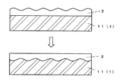
本発明は、少なくとも表面が熱可塑性樹脂層からなり、平滑な表面形状を有する基材の表面に、透明な硬化型樹脂からなり、前記熱可塑性樹脂層の表面よりも表面粗さの粗い、微細な凹凸状の表面形状を有する表面保護層を形成し、硬化させた後、該表面保護層上から熱圧プレス処理を施すことにより、該表面保護層の表面を平滑化させると同時に、該表面保護層と前記熱可塑性樹脂層との界面に、該熱圧プレス処理を施す前の該表面保護層の表面形状をほぼ反転させた微細な凹凸状の界面形状を形成することを特徴とする、表面が平滑な表面保護層の形成方法である。 In the present invention, at least the surface is made of a thermoplastic resin layer, the surface of the substrate having a smooth surface shape is made of a transparent curable resin, and the surface roughness is finer than the surface of the thermoplastic resin layer. After forming and curing a surface protective layer having an uneven surface shape, the surface of the surface protective layer is smoothed by subjecting the surface protective layer to a hot press process, and at the same time, The interface between the protective layer and the thermoplastic resin layer is characterized by forming a fine irregular interface shape that is substantially reversed from the surface shape of the surface protective layer prior to the hot-pressing treatment. This is a method for forming a surface protective layer having a smooth surface.
また本発明は、上記方法において、前記表面保護層の形成前の前記基材の表面粗さ(JIS B 0601(2001))が、算術平均粗さRaが1.0μm以下、最大高さ粗さRzが10.0μmであり、前記熱圧プレス処理の前の表面保護層の表面粗さが、算術平均粗さRaが0.5〜10.0μm、最大高さ粗さRzが2.0〜30.0μmであり、前記熱圧プレス処理の後の表面保護層の表面粗さが、算術平均粗さRaが1.0μm以下、最大高さ粗さRzが10.0μm以下であることを特徴とするものである。 Further, in the above method, the present invention provides that the surface roughness (JIS B 0601 (2001)) of the base material before formation of the surface protective layer is an arithmetic average roughness Ra of 1.0 μm or less, and a maximum height roughness. Rz is 10.0 μm, the surface roughness of the surface protective layer before the hot-pressing treatment is arithmetic average roughness Ra of 0.5 to 10.0 μm, and maximum height roughness Rz of 2.0 to The surface roughness of the surface protective layer after the hot pressing process is 30.0 μm, the arithmetic average roughness Ra is 1.0 μm or less, and the maximum height roughness Rz is 10.0 μm or less. It is what.
本発明によれば、表面保護層の表面は、光学特性や光沢意匠感に優れた鏡面状の平滑面である一方で、表面保護層と基材との界面には、微細な凹凸状の界面形状が形成されているため、該界面での反射光は、表面保護層の表面での反射光との干渉性が小さく、従って干渉縞を認識し難くなる。この効果は、基材と表面保護層との屈折率の差が大きな場合でも、大きな効果が得られるため、屈折率に制限されることなく、表面保護層の自由な樹脂設計が可能となり、表面保護層に要求される種々の機能性への対応も容易となるほか、特別な高価な添加剤を必要としないので、安価に製造可能であり、表面保護層の塗工用の溶剤も選ばず、さらには、表面保護層の塗工時に多少の塗工ムラが発生することがあっても、熱圧プレス処理によって矯正されるため、理想的な表面状態の製品を容易に製造することができる等、種々の実用上の利点を有するものである。 According to the present invention, the surface of the surface protective layer is a mirror-like smooth surface excellent in optical properties and glossy design, while the interface between the surface protective layer and the substrate is a fine uneven interface. Since the shape is formed, the reflected light at the interface has a low coherence with the reflected light on the surface of the surface protective layer, and it is difficult to recognize interference fringes. This effect can be obtained even when the difference in refractive index between the base material and the surface protective layer is large, so that the resin can be freely designed for the surface protective layer without being restricted by the refractive index. In addition to facilitating the various functionalities required for the protective layer, it does not require special expensive additives, so it can be manufactured at low cost, and the solvent for coating the surface protective layer can be selected. Furthermore, even if some coating unevenness may occur during the coating of the surface protective layer, it is corrected by the hot-pressing process, so that an ideal surface product can be easily manufactured. Have various practical advantages.
本発明の方法に使用する基材1は、少なくともその表面が熱可塑性樹脂層11からなるものであれば良く、全体が熱可塑性樹脂層11からなるものであっても良いし、表面の熱可塑性樹脂層11の裏面に任意の素材からなる層が積層されているものであっても良い。さらには、熱可塑性樹脂層11の表面に、本発明の方法に従って表面保護層2を形成した後、裏面に他の熱可塑性樹脂層若しくは任意の素材からなる層を積層することも、任意に実施することができる。
The
基材1の表面の熱可塑性樹脂層11としては、本発明において特に限定されるものではないが、後述する熱圧プレス処理の際にその表面形状が容易に変形されることが望ましいため、比較的軟化温度が低いものが好ましく使用される。具体的には、例えばポリエチレン、ポリプロピレン等のポリオレフィン系樹脂、ポリメチルメタクリレート等のアクリル系樹脂、1,4−シクロヘキサンジメタノール共重合ポリエステル(所謂PET−G)等の非晶質ポリエステル系樹脂、ポリ塩化ビニル樹脂等を好適に使用することができる。また、複数種類の熱可塑性樹脂の混合物や、複数層の熱可塑性樹脂層からなる積層体などであっても構わない。この熱可塑性樹脂層11の厚さは、あまり薄すぎると熱圧プレス処理が困難となるから、少なくとも20μm以上とすることが望ましい。
The thermoplastic resin layer 11 on the surface of the
表面保護層2の形成前の時点において、基材1の表面すなわち上記熱可塑性樹脂層11の表面は、可能な限り平滑な面とされていることが望ましく、具体的には、JIS B 0601(2001)に基づく(以下同じ)算術平均粗さRaが1.0μm以下、最大高さ粗さRzが10.0μm以下であることが望ましい。表面粗さがこれより粗いと、表面保護層2を設ける際に、熱可塑性樹脂層11の表面の凸形状の頂点において、表面保護層2の塗膜の厚みが極端に薄くなって、十分な表面性能を保持できなくなったり、熱可塑性樹脂層11自体の表面凹凸の大きさ及び/又はそれに起因する表面保護層2の塗工ムラのために、後の熱圧プレス処理によっても表面保護層2の表面の平滑化が困難となったりする場合があるからである。
It is desirable that the surface of the
熱可塑性樹脂層11の表面に形成する表面保護層2は、後の熱圧プレス処理によってそれ自体の厚みが変化することのない様に、硬化型樹脂によって形成する。該硬化型樹脂としては、例えばポリウレタン系樹脂、ポリエステル系樹脂、アクリル系樹脂等、種々の材料から任意に選択する事が出来、また、硬化方式も、例えば熱硬化型や、紫外線又は電子線等の電離放射線硬化型等、様々な方式から任意に選択する事ができる。また、複数種の樹脂を混合させても構わない。但し、硬化速度が著しく速く、且つ、硬化した樹脂の軟化温度が非常に高い場合には、熱圧プレス処理後に十分な表面平滑性が得られない場合があるので、硬化型樹脂の選択と熱圧プレス処理条件(温度、圧力等)との組み合わせには一定の配慮が必要である。
The surface
表面保護層2を形成する硬化型樹脂には、例えば耐擦傷性や易汚染除去性、耐候性、帯電防止性等、様々な機能性を付与することを目的として、種々の添加剤を混入させても良い。表面保護層2の形成方法としては、例えばロールコート法、グラビアコート法、ナイフコート法、ダイコート法、リップコート法、コンマコート法、フローコート法、ディップコート法、スプレーコート法等、公知の様々なコーティング方式から任意に選択することができる。表面保護層2の厚さは、薄すぎると保護効果が乏しい上に後述する微細な凹凸状の表面形状が十分に形成されず、厚すぎると後述する熱圧プレス処理による表面平滑化が困難となるので、一般的には平均厚さが2〜50μm程度の範囲内で適宜設計すると良い。
Various additives are mixed in the curable resin forming the surface
表面保護層2の塗工形成の際、その表面には、少なくとも基材1の表面をなす熱可塑性樹脂層11の表面よりも表面粗さの粗い、微細な凹凸状の表面形状を形成する必要がある。そうでないと、後の熱圧プレス処理の際に、熱可塑性樹脂層11と表面保護層2との界面に、必要な粗さの微細な凹凸状の界面形状を形成することが困難となり、その結果、十分な干渉縞抑制効果が得られないからである。その一方で、塗工形成した表面保護層2の表面粗さが多き過ぎる場合には、硬化型樹脂からなる表面保護層2の変形に対する抵抗力が大きいために、後の熱圧プレス処理後に十分な表面平滑性を得ることが出来なくなる恐れがある。係る事情を考慮すると、表面保護層2の表面粗さは、算術平均粗さRaが0.5〜10.0μm、最大高さ粗さRzが2.0〜30.0μmの範囲内となる様に形成することが望ましい。
When the surface
表面保護層2の表面に、上記の様な微細な凹凸状の表面形状を形成するための方法としては、従来公知の任意の方法によることができる。例えば、塗工液の粘度を通常より高めに調整して塗工後のレベリング不足による凹凸を発生させる方法や、全面に均一に塗工した後に微細なパターン状に再度塗工する方法、塗工液に有機物又は無機物の微細粒子(いわゆる艶消剤)を添加して塗膜の表面を荒らす方法、塗工後に気流を吹き付けて塗膜表面を波打たせる方法、塗膜を指触乾燥後に微細な凹凸状のエンボス加工を施す方法、塗膜の固化前に表面が微細な凹凸状の離型フィルムを被覆し固化後に剥離する方法等である。基材1が熱可塑性樹脂フィルムである場合には、グラビアコーティング法において通常より高粘度の塗工液を使用する方法によれば、他に特別な工程や処理を施す必要なく、通常の要領で高速生産が可能である利点がある。
As a method for forming the fine uneven surface shape as described above on the surface of the surface
表面保護層2の塗工後、熱圧プレス処理の前に、少なくとも該熱圧プレス処理によって表面保護層2が流動して厚みが変化することがない程度に、表面保護層2を硬化させる。このときの硬化の程度は、完全硬化させる必要は必ずしもなく、熱圧プレス処理条件下での流動性が失われさえすれば、半硬化状態であっても良い。完全硬化状態での表面保護層2の硬度が極めて高い場合には、熱圧プレス処理による表面保護層2の表面の平滑化自体が困難な場合があるので、その様な場合には、流動性を失う程度に半硬化させた状態で熱圧プレス処理を施し、しかる後に完全硬化させる方法が有効である。
After the coating of the surface
硬化方法は、表面保護層2に用いた硬化型樹脂の種類に応じて、加熱、電離放射線照射等から選べば良い。特に、熱硬化型樹脂と電離放射線硬化型樹脂とを併用した場合には、その一方のみを硬化させて半硬化状態とし、熱圧プレス処理後、他方を硬化させて完全硬化させる方法を用いると、完全硬化状態では熱圧プレス処理による平滑化が困難ないし不可能な高硬度の表面保護層2の形成が可能であり、しかも、半硬化状態における硬化度が安定しているので、得られる表面保護層2の表面平滑性も安定する利点がある。
The curing method may be selected from heating, ionizing radiation irradiation and the like according to the type of curable resin used for the surface
熱圧プレス処理の方法としては、表面が鏡面状の平滑面とされた、金属等の硬質の材質からなる鏡面エンボスロール又は鏡面エンボス版を使用して、熱ロールプレス方式又は平圧熱プレス方式で行うのが一般的である。特に、基材1がウェブ状(連続長尺状)である場合には、熱ロールプレス方式によるのが生産性に優れ好適である。処理条件としては、少なくとも基材1の表面の熱可塑性樹脂層11の表面形状が変化し得る温度、つまり一般的には熱変形温度以上の温度に加熱することが必要である。
As a method of the hot press process, a mirror surface embossing roll or a mirror surface embossing plate made of a hard material such as a metal whose surface is a mirror-like smooth surface is used. It is common to do this. In particular, when the
この熱圧プレス処理によって、前記した微細な凹凸状の表面形状を有していた表面保護層2が、平滑なエンボスロール又はエンボス版によって押し潰されて表面が平滑に均され、その際、処理前に表面保護層2の表面が周囲に対して凸部となっていた個所、すなわち表面保護層2が局所的に周囲より厚く形成されていた個所では、表面が周囲と同じ高さに均されることによって、裏面すなわち熱可塑性樹脂層11との界面は、熱可塑性樹脂層11中へめり込む様にして下方へ移動するので、その結果、表面保護層2と熱可塑性樹脂層11との界面には、処理前の表面保護層2の表面形状を反転させた形状にほぼ相当する、微細な凹凸状の界面形状が形成される。
By this hot pressing process, the surface
この様に、表面保護層2の表面が鏡面状の平滑面となる一方で、表面保護層2と熱可塑性樹脂層11との界面が平滑でなくなることによって、界面での反射光が散乱を起こし、表面保護層2の表面での反射光との間の干渉性が弱まる効果を生む。その結果、表面保護層2の表面側から観察される干渉縞の幅は非常に小さいものとなり、しかも干渉縞の強度も非常に弱いものとなるので、目視で確認する事が困難な程度にまで干渉縞の発生が抑制される。
Thus, while the surface of the surface
ここで、熱圧プレス処理後の表面保護層2の表面粗さは、目視にて十分に鏡面状の平滑面として観察される様に、算術平均粗さRaが1.0μm以下、最大高さ粗さRzが10.0μm以下であることが望ましい。係る平滑面を形成するためには、熱圧プレス処理に使用する鏡面エンボスロール又は鏡面エンボス版としては、少なくともこれと同等以上の表面平滑度(表面粗さは上記以下)を有するものを使用すべきことは、言うまでもない。
Here, the surface roughness of the surface
なお、本発明の製造方法に従って化粧材を製造する場合には、熱圧プレス処理後の表面の鮮映度Gd値が0.8以上であることが好ましい。そうすることによって、化粧材表面に物体等の反射像が大きく歪むことなく映り込む、所謂ハイグロス仕上げと言われる効果が生まれる。なお、上記Gd値とは、(財)日本色彩研究所が設定した鮮映度(distinctness of image gloss)を表す指標である。 In addition, when manufacturing a cosmetic material according to the manufacturing method of this invention, it is preferable that the surface definition Gd value of the surface after a hot press process is 0.8 or more. By doing so, an effect referred to as a so-called high gloss finish in which a reflected image of an object or the like is reflected on the surface of the decorative material without being greatly distorted is produced. Note that the Gd value is an index that represents the distinctness of image gloss set by the Japan Color Research Institute.
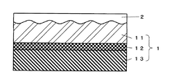
本発明の方法を化粧材、特に化粧シートの製造に応用する場合には、例えば、熱可塑性樹脂層11としての透明熱可塑性樹脂フィルムを基材1として、上述した通りの方法によって表面保護層2を形成した後、該表面保護層2とは反対側の面に絵柄層12を設けることができる(図2)。絵柄層12は、種々の印刷手法によって直接印刷して設けても良いし、一旦剥離フィルム上に設けられた絵柄層12を転写法によって透明熱可塑性樹脂フィルムの裏面に付与しても良い。絵柄層12の全体又は一部を隠蔽層として形成しても良い。
When the method of the present invention is applied to the production of a decorative material, particularly a decorative sheet, for example, the surface
また、熱可塑性樹脂層11としての透明熱可塑性樹脂フィルム11の表面保護層2とは反対側の面に、絵柄層12を介して又は介さずに、他の熱可塑性樹脂フィルム13を設けても良い(図3)。この熱可塑性樹脂フィルム13は、化粧シートの隠蔽性を向上させたり、シート剛性を増したり、加工性を向上させたりするなどの目的で設けられるものであり、その熱可塑性樹脂の種類としては、上記熱可塑性樹脂層11の場合と同様の種々の材料の中から任意に選定する事ができ、透明であっても着色されていても構わない。
Further, another thermoplastic resin film 13 may be provided on the surface opposite to the surface
係る構成の化粧シートの製造手順としては、透明熱可塑性樹脂フィルム11に表面保護層2を形成してから裏面に絵柄層12を設け、さらに他の熱可塑性樹脂フィルム13を積層しても良いし、予め表面に絵柄層12を設けた熱可塑性樹脂フィルム13を、表面保護層2を設けた透明熱可塑性樹脂フィルム11の裏面に積層しても良く、更には、予め透明熱可塑性樹脂フィルム11の裏面に絵柄層12を介して他の熱可塑性樹脂フィルム13を積層してから、透明熱可塑性樹脂フィルムの表面に表面保護層2を形成しても良い。さらには、下側の熱可塑性樹脂フィルム13の裏面に、化粧シートの被貼着基材との密着性を向上させる目的でプライマー処理を設けても良い。
As a manufacturing procedure of the decorative sheet having such a configuration, after forming the surface
なお、表面保護層2の形成における塗工、硬化、熱圧プレス処理の3つの工程は、必ずしも連続工程として実施する必要はなく、塗工と硬化との間及び/又は硬化と熱圧プレス処理との間に、絵柄層12の形成や他の熱可塑性樹脂フィルム13の積層等の、他の工程が挟まっても良い。例えば、透明熱可塑性樹脂フィルム11と他の熱可塑性樹脂フィルム13との積層を熱ラミネート法によって行う場合には、予め表面に表面保護層2を塗工形成、硬化させた熱圧プレス処理前の透明熱可塑性樹脂フィルム11と、他の熱可塑性樹脂フィルム13とを、その一方に形成した絵柄層12を介して熱ラミネートさせる際に、その表面保護層2側に当接させる加圧ロールとして、表面が鏡面状の平滑面とされた鏡面ロールを使用することによって、透明熱可塑性樹脂フィルム11と他の熱可塑性樹脂フィルム13とを熱ラミネートすると同時に表面保護層2の表面に熱圧プレス処理を施す方法を採用すれば、従来の製造方法と比較して特別な工程を増加させることなく、簡便且つ能率的に製造できる利点がある。
Note that the three steps of coating, curing, and hot-pressing in the formation of the surface
厚さ200μmの透明なポリメチルメタクリレート樹脂フィルム「サンデュレン」(鐘淵化学(株)製;Ra=0.2μm、Rz=1.2μm)の片面に、表面保護層として、シリコーン変性イソシアネート硬化型ポリウレタン系樹脂「YL341」(東洋インキ製造(株)製)を、版深140μmのグラビアロールを用い、ダイレクトグラビアコート法により塗工し、乾燥固化させた。この時の塗膜面の表面粗さは、Ra=2.2μm、Rz=5.8μmであった。しかる後、表面粗さがRa=0.1μm、Rz=0.9μmであるシリンダー状の鏡面エンボスロールを用いて、フィルム温度が125℃となる条件下で連続的に熱圧プレス処理を行った。処理後の塗膜面の表面粗さは、Ra=0.4μm、Rz=1.4μmであった。また、この時の表面保護層の平均厚さは9.2μmであった。 Silicone-modified isocyanate-cured polyurethane as a surface protective layer on one side of a transparent polymethylmethacrylate resin film “Sanduren” (manufactured by Kaneka Chemical Co., Ltd .; Ra = 0.2 μm, Rz = 1.2 μm) having a thickness of 200 μm The system resin “YL341” (manufactured by Toyo Ink Manufacturing Co., Ltd.) was applied by a direct gravure coating method using a gravure roll having a plate depth of 140 μm and dried and solidified. The surface roughness of the coating film at this time was Ra = 2.2 μm and Rz = 5.8 μm. Thereafter, using a cylindrical mirror surface embossing roll having a surface roughness of Ra = 0.1 μm and Rz = 0.9 μm, a hot press process was continuously performed under the condition that the film temperature was 125 ° C. . The surface roughness of the coating surface after the treatment was Ra = 0.4 μm and Rz = 1.4 μm. At this time, the average thickness of the surface protective layer was 9.2 μm.
こうして得た表面保護層付き透明フィルムの表面保護層側とは反対側の面に、別途ウレタン系印刷インキ「ラミスター」(東洋インキ製造(株)製)を用いてグラビア印刷法による絵柄層を設けた厚さ150μmの着色ポリプロピレンフィルムの絵柄層面を、ドライラミネート法により貼り合わせて、化粧シートを作製した。 On the surface opposite to the surface protective layer side of the transparent film with the surface protective layer thus obtained, a pattern layer by gravure printing method is separately provided using urethane-based printing ink "Lamistor" (manufactured by Toyo Ink Manufacturing Co., Ltd.) The decorative layer was prepared by pasting the pattern layer surfaces of a colored polypropylene film having a thickness of 150 μm by a dry laminating method.
厚さ300μmの透明非晶性ポリエステルフィルム「NAGASE A−PET」(長瀬産業(株)製;Ra=0.4μm、Rz=2.1μm)の片面に、表面保護層としてウレタンアクリレート系の紫外線硬化型樹脂(日本ペイント(株)製)を、版深200μmのグラビアロールを用い、ダイレクトリバースグラビアコート法により塗工しながら、同一ライン上で紫外線照射を行い、更に同一ライン上でフィルム温度が140℃となる条件下で、表面粗さがRa=0.1μm、Rz=0.9μmであるシリンダー状の鏡面エンボスロールを用いて、熱圧プレス処理を行った。この時、紫外線照射後、熱圧プレス処理前の塗膜面の表面粗さは、Ra=2.1μm、Rz=12.5μm、熱圧プレス処理後は、Ra=0.2μm、Rz=1.1μmであった。また、この時の表面保護層の平均厚さは15.2μmであった。 Transparent acrylic polyester film “NAGASE A-PET” (manufactured by Nagase Sangyo Co., Ltd .; Ra = 0.4 μm, Rz = 2.1 μm) with a thickness of 300 μm and urethane acrylate UV curing as a surface protective layer While applying a mold resin (manufactured by Nippon Paint Co., Ltd.) by a direct reverse gravure coating method using a gravure roll with a plate depth of 200 μm, the film temperature is 140 on the same line. Under the conditions of a temperature of 0 ° C., a hot-pressing treatment was performed using a cylindrical mirror surface embossing roll having a surface roughness of Ra = 0.1 μm and Rz = 0.9 μm. At this time, the surface roughness of the coating film surface after irradiation with ultraviolet rays and before hot pressing is Ra = 2.1 μm, Rz = 12.5 μm, and after hot pressing, Ra = 0.2 μm, Rz = 1. .1 μm. At this time, the average thickness of the surface protective layer was 15.2 μm.
こうして得た表面保護層付き透明フィルムの裏面に、アルミニウム粉を30重量%添加したポリウレタン系樹脂「ラミスター」(東洋インキ製造(株)製)をダイレクトグラビアコート法により塗工して、化粧シートを作製した。 A polyurethane-based resin “Lamistar” (manufactured by Toyo Ink Mfg. Co., Ltd.) added with 30% by weight of aluminum powder was applied to the back surface of the transparent film with a surface protective layer thus obtained by a direct gravure coating method. Produced.
〔比較例1〕
上記実施例1において、表面保護層の塗工条件を、塗膜面の平滑性が最も高まる様に調整し、熱圧プレス処理を行わずに、その他は同一条件にて表面保護層付き透明フィルムを作製したところ、表面保護層の表面粗さはRa=0.4μm、Rz=1.5μm、平均厚さは9.4μmであった。以下、上記実施例1と同様にして化粧シートを作製した。
[Comparative Example 1]
In Example 1 above, the coating condition of the surface protective layer is adjusted so that the smoothness of the coating film surface is the highest, and the transparent film with the surface protective layer is applied under the same conditions without performing the hot press process. As a result, the surface roughness of the surface protective layer was Ra = 0.4 μm, Rz = 1.5 μm, and the average thickness was 9.4 μm. Thereafter, a decorative sheet was produced in the same manner as in Example 1.
〔比較例2〕
上記実施例2において、表面保護層の塗工条件を、塗膜面の平滑性が最も高まる様に調整し、熱圧プレス処理を行わずに、その他は同一条件にて表面保護層付き透明フィルムを作製したところ、表面保護層の表面粗さはRa=0.2μm、Rz=1.2μmであった。以下、上記実施例2と同様にして化粧シートを作製した。
[Comparative Example 2]
In Example 2 above, the coating condition of the surface protective layer was adjusted so that the smoothness of the coating film surface was the highest, and the transparent film with the surface protective layer was applied under the same conditions without performing the hot press process. As a result, the surface roughness of the surface protective layer was Ra = 0.2 μm and Rz = 1.2 μm. Thereafter, a decorative sheet was produced in the same manner as in Example 2.
〔評価〕
上記実施例1〜2及び比較例1〜2により得られた化粧シートを、厚さ24mmの中密度繊維板の表面にラミネートして作製した化粧板を、蛍光灯照明下で床面と垂直になるように立て、化粧板の正面方向に10m離れた位置から化粧板表面を目視で確認しながら近づいて行き、干渉縞が認識できるようになる最大距離を測定した。その結果を下記の表に示す。
[Evaluation]
A decorative board produced by laminating the decorative sheets obtained in Examples 1 and 2 and Comparative Examples 1 and 2 on the surface of a medium density fiber board having a thickness of 24 mm is perpendicular to the floor surface under fluorescent lamp illumination. The maximum distance at which interference fringes can be recognized was measured by approaching the surface of the decorative board while visually confirming the surface of the decorative board from a position 10 m away from the front of the decorative board. The results are shown in the table below.
〔評価結果〕
最大干渉縞認識距離
実施例1 0.10m
実施例2 0.08m
比較例1 3.2m
比較例2 2.9m
〔Evaluation results〕
Maximum interference fringe recognition distance Example 1 0.10 m
Example 2 0.08 m
Comparative Example 1 3.2 m
Comparative Example 2 2.9 m
1 基材
11 熱可塑性樹脂層(透明熱可塑性樹脂フィルム)
12 絵柄層
13 熱可塑性樹脂フィルム
2 表面保護層
1 Base material 11 Thermoplastic resin layer (transparent thermoplastic resin film)
12 picture layer 13
Claims (2)
Priority Applications (1)
| Application Number | Priority Date | Filing Date | Title |
|---|---|---|---|
| JP2003364193A JP2005125627A (en) | 2003-10-24 | 2003-10-24 | Method for forming surface protecting layer with smooth surface |
Applications Claiming Priority (1)
| Application Number | Priority Date | Filing Date | Title |
|---|---|---|---|
| JP2003364193A JP2005125627A (en) | 2003-10-24 | 2003-10-24 | Method for forming surface protecting layer with smooth surface |
Publications (2)
| Publication Number | Publication Date |
|---|---|
| JP2005125627A true JP2005125627A (en) | 2005-05-19 |
| JP2005125627A5 JP2005125627A5 (en) | 2006-07-13 |
Family
ID=34643244
Family Applications (1)
| Application Number | Title | Priority Date | Filing Date |
|---|---|---|---|
| JP2003364193A Pending JP2005125627A (en) | 2003-10-24 | 2003-10-24 | Method for forming surface protecting layer with smooth surface |
Country Status (1)
| Country | Link |
|---|---|
| JP (1) | JP2005125627A (en) |
Cited By (7)
| Publication number | Priority date | Publication date | Assignee | Title |
|---|---|---|---|---|
| JP2009291961A (en) * | 2008-06-02 | 2009-12-17 | Toppan Cosmo Inc | Decorative sheet |
| JP2010030130A (en) * | 2008-07-29 | 2010-02-12 | Toppan Cosmo Inc | Monolayer decorative sheet |
| JP2011121304A (en) * | 2009-12-11 | 2011-06-23 | Mitsubishi Chemicals Corp | Laminate |
| WO2011096320A1 (en) * | 2010-02-05 | 2011-08-11 | コニカミノルタオプト株式会社 | Film mirror, film mirror for solar thermal power generation, and reflection device for solar photovoltaic power generation |
| WO2012043606A1 (en) * | 2010-10-01 | 2012-04-05 | コニカミノルタオプト株式会社 | Film mirror for solar power generation, process for manufacturing film mirror for solar power generation, and reflection device for solar power generation |
| JP2016093961A (en) * | 2014-11-14 | 2016-05-26 | 大阪シーリング印刷株式会社 | Packaging sheet, and packaging container and packaging method each using the same |
| KR20200000811A (en) * | 2018-06-25 | 2020-01-03 | 스미또모 가가꾸 가부시키가이샤 | Liquid application apparatus |
-
2003
- 2003-10-24 JP JP2003364193A patent/JP2005125627A/en active Pending
Cited By (11)
| Publication number | Priority date | Publication date | Assignee | Title |
|---|---|---|---|---|
| JP2009291961A (en) * | 2008-06-02 | 2009-12-17 | Toppan Cosmo Inc | Decorative sheet |
| JP2010030130A (en) * | 2008-07-29 | 2010-02-12 | Toppan Cosmo Inc | Monolayer decorative sheet |
| JP2011121304A (en) * | 2009-12-11 | 2011-06-23 | Mitsubishi Chemicals Corp | Laminate |
| WO2011096320A1 (en) * | 2010-02-05 | 2011-08-11 | コニカミノルタオプト株式会社 | Film mirror, film mirror for solar thermal power generation, and reflection device for solar photovoltaic power generation |
| JP5747823B2 (en) * | 2010-02-05 | 2015-07-15 | コニカミノルタ株式会社 | Film mirror, film mirror for solar power generation and reflector for solar power generation |
| US9110228B2 (en) | 2010-02-05 | 2015-08-18 | Konica Minolta Advanced Layers, Inc. | Film mirror, film mirror for solar power generation and reflection device for solar power generation |
| WO2012043606A1 (en) * | 2010-10-01 | 2012-04-05 | コニカミノルタオプト株式会社 | Film mirror for solar power generation, process for manufacturing film mirror for solar power generation, and reflection device for solar power generation |
| JPWO2012043606A1 (en) * | 2010-10-01 | 2014-02-24 | コニカミノルタ株式会社 | Film mirror for solar power generation, method for manufacturing film mirror for solar power generation, and reflector for solar power generation |
| JP2016093961A (en) * | 2014-11-14 | 2016-05-26 | 大阪シーリング印刷株式会社 | Packaging sheet, and packaging container and packaging method each using the same |
| KR20200000811A (en) * | 2018-06-25 | 2020-01-03 | 스미또모 가가꾸 가부시키가이샤 | Liquid application apparatus |
| KR102649141B1 (en) | 2018-06-25 | 2024-03-18 | 스미또모 가가꾸 가부시키가이샤 | Liquid application apparatus |
Similar Documents
| Publication | Publication Date | Title |
|---|---|---|
| JP5742972B2 (en) | Method for producing foam wallpaper | |
| MXPA02010523A (en) | Method for producing floor finish and wall finish with differential gloss decoration effect and resulting products. | |
| TW201604037A (en) | Transfer film and transfer molded article using same | |
| JP2022066281A (en) | Whiteboard and projection screen combined film | |
| TW201604034A (en) | Transfer film and transfer molded article using same | |
| JP2006239967A (en) | Transfer sheet | |
| JP2005125627A (en) | Method for forming surface protecting layer with smooth surface | |
| WO2015072119A1 (en) | Transfer film for in-mold molding and molded article using same | |
| KR102630911B1 (en) | Surface uneven sheets, screens, video display systems and transfer rolls | |
| JP2019038233A (en) | Decorative sheet, structure including decorative sheet and method for producing decorative sheet | |
| JP2005119022A (en) | Manufacturing method of decorative material | |
| KR102217433B1 (en) | Decorative sheet and method for manufacturing the same | |
| JP5382249B2 (en) | Foam wallpaper | |
| KR100704462B1 (en) | The method of forming embossing pattern by heating press mold partially on the printing surface laminated with thermal laminate film | |
| JPH11254885A (en) | Sheet for white board, and its manufacture | |
| JP2003138036A (en) | Mat printing film and mat molded product | |
| JPS63159098A (en) | Sheet material for writing and manufacture thereof | |
| JP3275414B2 (en) | Method for producing uneven decorative sheet having scratch resistance | |
| JP2019144396A (en) | Method for manufacturing laminate for display | |
| JP7405224B2 (en) | makeup sheet | |
| JPH01295848A (en) | Manufacture of decorative sheet | |
| JPH06184952A (en) | Sueded decorative sheet and its production | |
| JP2022177514A (en) | Decorative film molding body, method of manufacturing decorative film molding body, satin plating-like product, container, housing, vehicular interior and exterior member | |
| JP2005036168A (en) | Acrylic mat film, acrylic mat printed film, three-dimensional form acrylic mat printed film, mat printed sheet, and mat molded article | |
| JP2021172033A (en) | Decorative sheet and method for manufacturing the same, decorative laminate and method for repairing the same |
Legal Events
| Date | Code | Title | Description |
|---|---|---|---|
| A521 | Written amendment |
Free format text: JAPANESE INTERMEDIATE CODE: A523 Effective date: 20060529 |
|
| A621 | Written request for application examination |
Free format text: JAPANESE INTERMEDIATE CODE: A621 Effective date: 20060919 |
|
| A977 | Report on retrieval |
Free format text: JAPANESE INTERMEDIATE CODE: A971007 Effective date: 20081226 |
|
| A131 | Notification of reasons for refusal |
Free format text: JAPANESE INTERMEDIATE CODE: A131 Effective date: 20090203 |
|
| A02 | Decision of refusal |
Free format text: JAPANESE INTERMEDIATE CODE: A02 Effective date: 20090616 |