JP2005123775A - REPRODUCTION DEVICE, REPRODUCTION METHOD, REPRODUCTION PROGRAM, AND RECORDING MEDIUM - Google Patents
REPRODUCTION DEVICE, REPRODUCTION METHOD, REPRODUCTION PROGRAM, AND RECORDING MEDIUM Download PDFInfo
- Publication number
- JP2005123775A JP2005123775A JP2003354741A JP2003354741A JP2005123775A JP 2005123775 A JP2005123775 A JP 2005123775A JP 2003354741 A JP2003354741 A JP 2003354741A JP 2003354741 A JP2003354741 A JP 2003354741A JP 2005123775 A JP2005123775 A JP 2005123775A
- Authority
- JP
- Japan
- Prior art keywords
- image data
- storage means
- plane
- recording medium
- moving image
- Prior art date
- Legal status (The legal status is an assumption and is not a legal conclusion. Google has not performed a legal analysis and makes no representation as to the accuracy of the status listed.)
- Pending
Links
Images
Classifications
-
- H—ELECTRICITY
- H04—ELECTRIC COMMUNICATION TECHNIQUE
- H04N—PICTORIAL COMMUNICATION, e.g. TELEVISION
- H04N5/00—Details of television systems
- H04N5/76—Television signal recording
- H04N5/91—Television signal processing therefor
- H04N5/93—Regeneration of the television signal or of selected parts thereof
- H04N5/9305—Regeneration of the television signal or of selected parts thereof involving the mixing of the reproduced video signal with a non-recorded signal, e.g. a text signal
-
- H—ELECTRICITY
- H04—ELECTRIC COMMUNICATION TECHNIQUE
- H04N—PICTORIAL COMMUNICATION, e.g. TELEVISION
- H04N5/00—Details of television systems
- H04N5/44—Receiver circuitry for the reception of television signals according to analogue transmission standards
- H04N5/445—Receiver circuitry for the reception of television signals according to analogue transmission standards for displaying additional information
- H04N5/45—Picture in picture, e.g. displaying simultaneously another television channel in a region of the screen
-
- G—PHYSICS
- G11—INFORMATION STORAGE
- G11B—INFORMATION STORAGE BASED ON RELATIVE MOVEMENT BETWEEN RECORD CARRIER AND TRANSDUCER
- G11B20/00—Signal processing not specific to the method of recording or reproducing; Circuits therefor
- G11B20/10—Digital recording or reproducing
-
- H—ELECTRICITY
- H04—ELECTRIC COMMUNICATION TECHNIQUE
- H04N—PICTORIAL COMMUNICATION, e.g. TELEVISION
- H04N21/00—Selective content distribution, e.g. interactive television or video on demand [VOD]
- H04N21/40—Client devices specifically adapted for the reception of or interaction with content, e.g. set-top-box [STB]; Operations thereof
- H04N21/43—Processing of content or additional data, e.g. demultiplexing additional data from a digital video stream; Elementary client operations, e.g. monitoring of home network or synchronising decoder's clock; Client middleware
- H04N21/431—Generation of visual interfaces for content selection or interaction; Content or additional data rendering
- H04N21/4312—Generation of visual interfaces for content selection or interaction; Content or additional data rendering involving specific graphical features, e.g. screen layout, special fonts or colors, blinking icons, highlights or animations
- H04N21/4314—Generation of visual interfaces for content selection or interaction; Content or additional data rendering involving specific graphical features, e.g. screen layout, special fonts or colors, blinking icons, highlights or animations for fitting data in a restricted space on the screen, e.g. EPG data in a rectangular grid
-
- H—ELECTRICITY
- H04—ELECTRIC COMMUNICATION TECHNIQUE
- H04N—PICTORIAL COMMUNICATION, e.g. TELEVISION
- H04N21/00—Selective content distribution, e.g. interactive television or video on demand [VOD]
- H04N21/40—Client devices specifically adapted for the reception of or interaction with content, e.g. set-top-box [STB]; Operations thereof
- H04N21/43—Processing of content or additional data, e.g. demultiplexing additional data from a digital video stream; Elementary client operations, e.g. monitoring of home network or synchronising decoder's clock; Client middleware
- H04N21/431—Generation of visual interfaces for content selection or interaction; Content or additional data rendering
- H04N21/4312—Generation of visual interfaces for content selection or interaction; Content or additional data rendering involving specific graphical features, e.g. screen layout, special fonts or colors, blinking icons, highlights or animations
- H04N21/4316—Generation of visual interfaces for content selection or interaction; Content or additional data rendering involving specific graphical features, e.g. screen layout, special fonts or colors, blinking icons, highlights or animations for displaying supplemental content in a region of the screen, e.g. an advertisement in a separate window
-
- H—ELECTRICITY
- H04—ELECTRIC COMMUNICATION TECHNIQUE
- H04N—PICTORIAL COMMUNICATION, e.g. TELEVISION
- H04N21/00—Selective content distribution, e.g. interactive television or video on demand [VOD]
- H04N21/40—Client devices specifically adapted for the reception of or interaction with content, e.g. set-top-box [STB]; Operations thereof
- H04N21/43—Processing of content or additional data, e.g. demultiplexing additional data from a digital video stream; Elementary client operations, e.g. monitoring of home network or synchronising decoder's clock; Client middleware
- H04N21/44—Processing of video elementary streams, e.g. splicing a video clip retrieved from local storage with an incoming video stream or rendering scenes according to encoded video stream scene graphs
- H04N21/4402—Processing of video elementary streams, e.g. splicing a video clip retrieved from local storage with an incoming video stream or rendering scenes according to encoded video stream scene graphs involving reformatting operations of video signals for household redistribution, storage or real-time display
- H04N21/440218—Processing of video elementary streams, e.g. splicing a video clip retrieved from local storage with an incoming video stream or rendering scenes according to encoded video stream scene graphs involving reformatting operations of video signals for household redistribution, storage or real-time display by transcoding between formats or standards, e.g. from MPEG-2 to MPEG-4
-
- H—ELECTRICITY
- H04—ELECTRIC COMMUNICATION TECHNIQUE
- H04N—PICTORIAL COMMUNICATION, e.g. TELEVISION
- H04N21/00—Selective content distribution, e.g. interactive television or video on demand [VOD]
- H04N21/40—Client devices specifically adapted for the reception of or interaction with content, e.g. set-top-box [STB]; Operations thereof
- H04N21/47—End-user applications
-
- H—ELECTRICITY
- H04—ELECTRIC COMMUNICATION TECHNIQUE
- H04N—PICTORIAL COMMUNICATION, e.g. TELEVISION
- H04N5/00—Details of television systems
- H04N5/222—Studio circuitry; Studio devices; Studio equipment
- H04N5/262—Studio circuits, e.g. for mixing, switching-over, change of character of image, other special effects ; Cameras specially adapted for the electronic generation of special effects
- H04N5/272—Means for inserting a foreground image in a background image, i.e. inlay, outlay
-
- H—ELECTRICITY
- H04—ELECTRIC COMMUNICATION TECHNIQUE
- H04N—PICTORIAL COMMUNICATION, e.g. TELEVISION
- H04N5/00—Details of television systems
- H04N5/44—Receiver circuitry for the reception of television signals according to analogue transmission standards
- H04N5/445—Receiver circuitry for the reception of television signals according to analogue transmission standards for displaying additional information
-
- H—ELECTRICITY
- H04—ELECTRIC COMMUNICATION TECHNIQUE
- H04N—PICTORIAL COMMUNICATION, e.g. TELEVISION
- H04N5/00—Details of television systems
- H04N5/76—Television signal recording
- H04N5/91—Television signal processing therefor
- H04N5/92—Transformation of the television signal for recording, e.g. modulation, frequency changing; Inverse transformation for playback
- H04N5/926—Transformation of the television signal for recording, e.g. modulation, frequency changing; Inverse transformation for playback by pulse code modulation
-
- H—ELECTRICITY
- H04—ELECTRIC COMMUNICATION TECHNIQUE
- H04N—PICTORIAL COMMUNICATION, e.g. TELEVISION
- H04N5/00—Details of television systems
- H04N5/76—Television signal recording
- H04N5/91—Television signal processing therefor
- H04N5/93—Regeneration of the television signal or of selected parts thereof
-
- H—ELECTRICITY
- H04—ELECTRIC COMMUNICATION TECHNIQUE
- H04N—PICTORIAL COMMUNICATION, e.g. TELEVISION
- H04N9/00—Details of colour television systems
- H04N9/79—Processing of colour television signals in connection with recording
- H04N9/80—Transformation of the television signal for recording, e.g. modulation, frequency changing; Inverse transformation for playback
- H04N9/82—Transformation of the television signal for recording, e.g. modulation, frequency changing; Inverse transformation for playback the individual colour picture signal components being recorded simultaneously only
- H04N9/8205—Transformation of the television signal for recording, e.g. modulation, frequency changing; Inverse transformation for playback the individual colour picture signal components being recorded simultaneously only involving the multiplexing of an additional signal and the colour video signal
- H04N9/8227—Transformation of the television signal for recording, e.g. modulation, frequency changing; Inverse transformation for playback the individual colour picture signal components being recorded simultaneously only involving the multiplexing of an additional signal and the colour video signal the additional signal being at least another television signal
Landscapes
- Engineering & Computer Science (AREA)
- Signal Processing (AREA)
- Multimedia (AREA)
- Business, Economics & Management (AREA)
- Marketing (AREA)
- Controls And Circuits For Display Device (AREA)
- Studio Circuits (AREA)
- Television Signal Processing For Recording (AREA)
- Signal Processing For Digital Recording And Reproducing (AREA)
- Indexing, Searching, Synchronizing, And The Amount Of Synchronization Travel Of Record Carriers (AREA)
- Management Or Editing Of Information On Record Carriers (AREA)
Abstract
【課題】 BD−ROMにおいて、ピクチャインピクチャ機能や壁紙表示機能を実現する。
【解決手段】 それぞれ動画、字幕およびグラフィクスを表示するプレーン10、11および12に対して、動画を表示する第2ビデオプレーン50を追加する。第2ビデオプレーン50およびビデオプレーン10の出力は、スイッチ51により画素単位で選択される。第2ビデオプレーン50に縮小動画データを格納し、スイッチ51を縮小動画データの表示位置に対応して画素単位で切り替え制御することで、ビデオプレーン10の動画データに対して第2ビデオプレーン50の縮小動画データが子画面表示される。ビデオプレーン10に、動画データの代わりに壁紙画像データを格納することで、恰も縮小動画データの背景に壁紙が表示されているかのような表示画面が得られる。
【選択図】 図8PROBLEM TO BE SOLVED: To realize a picture-in-picture function and a wallpaper display function in a BD-ROM.
A second video plane 50 for displaying moving images is added to planes 10, 11, and 12 for displaying moving images, subtitles, and graphics, respectively. The outputs of the second video plane 50 and the video plane 10 are selected by the switch 51 in units of pixels. The reduced video data is stored in the second video plane 50, and the switch 51 is controlled to be switched in units of pixels corresponding to the display position of the reduced video data. Reduced video data is displayed on a small screen. By storing wallpaper image data instead of moving image data in the video plane 10, a display screen as if the wallpaper is displayed on the background of the reduced moving image data can be obtained.
[Selection] Figure 8
Description
この発明は、ブルーレイディスク(Blu-ray Disc)といった大容量の記録媒体に記録されたプログラムに対してピクチャインピクチャを実現可能とする再生装置、再生方法、再生プログラムおよび記録媒体に関する。 The present invention relates to a playback apparatus, a playback method, a playback program, and a recording medium that can realize picture-in-picture for a program recorded on a large-capacity recording medium such as a Blu-ray Disc.
近年、記録可能で記録再生装置から取り外し可能なディスク型記録媒体の規格として、Blu−ray Disc(ブルーレイディスク)規格が提案されている。Blu−ray Disc規格では、記録媒体として直径12cm、カバー層0.1mmのディスクを用い、光学系として波長405nmの青紫色レーザ、開口数0.85の対物レンズを用いて、最大で27GB(ギガバイト)の記録容量を実現している。これにより、日本のBSディジタルハイビジョン放送を、画質を劣化させることなく2時間以上記録することが可能である。 In recent years, the Blu-ray Disc (Blu-ray Disc) standard has been proposed as a standard for a disc-type recording medium that can be recorded and can be removed from a recording / reproducing apparatus. In the Blu-ray Disc standard, a disk having a diameter of 12 cm and a cover layer of 0.1 mm is used as a recording medium, a blue-violet laser having a wavelength of 405 nm and an objective lens having a numerical aperture of 0.85 are used as an optical system, and the maximum size is 27 GB (gigabytes). ) Recording capacity. As a result, it is possible to record Japanese BS digital high-definition broadcasting for 2 hours or more without degrading the image quality.
この記録可能光ディスクに記録するAV(Audio/Video)信号のソース(供給源)としては、従来からの、例えばアナログテレビジョン放送によるアナログ信号によるものと、例えばBSディジタル放送をはじめとするディジタルテレビジョン放送によるディジタル信号によるものとが想定されている。Blu−ray Disc規格では、これらの放送によるAV信号を記録する方法を定めた規格は、既に作られている。 As a source (supply source) of an AV (Audio / Video) signal to be recorded on the recordable optical disc, a conventional analog signal by analog television broadcast, for example, digital television including BS digital broadcast, for example. It is assumed to be a digital signal by broadcasting. In the Blu-ray Disc standard, a standard that defines a method for recording AV signals by these broadcasts has already been created.
一方で、現状のBlu−ray Discの派生規格として、映画や音楽などが予め記録された、再生専用の記録媒体を開発する動きが進んでいる。映画や音楽を記録するためのディスク状記録媒体としては、既にDVD(Digital Versatile Disc)が広く普及しているが、このBlu−ray Discの規格に基づいた再生専用光ディスクは、Blu−ray Discの大容量および高速な転送速度などを活かし、ハイビジョン映像を高画質なままで2時間以上収録できる点が、既存のDVDとは大きく異なり、優位である。以下では、Blu−ray Discの派生規格の再生専用の記録媒体をBD−ROM(Blu-ray Disc-Read Only Memory)と称し、記録可能なBlu−ray Discと区別する。 On the other hand, as a standard derived from the current Blu-ray Disc, there is a movement to develop a read-only recording medium in which movies and music are recorded in advance. As a disc-shaped recording medium for recording movies and music, a DVD (Digital Versatile Disc) has already been widely used. A reproduction-only optical disc based on the Blu-ray Disc standard is a Blu-ray Disc standard. It differs from existing DVDs in that it can record high-definition video for 2 hours or more with high capacity and high transfer speed. Hereinafter, a reproduction-only recording medium of a Blu-ray Disc derived standard is referred to as a BD-ROM (Blu-ray Disc-Read Only Memory) and is distinguished from a recordable Blu-ray Disc.
一方で、現状のBlu−ray Discの規格では、ディスクに記録されている映像コンテンツの一覧を画面表示する方法や、その一覧表上にカーソルを表示させ、再生したい映像コンテンツをユーザに選択させるなどといったユーザインターフェイスに関する機能が定められていない。これらの機能は、Blu−ray Discに対する記録再生を行う記録再生装置本体によって実現されている。そのため、同一の記録媒体を再生した場合でも、再生に用いた記録再生装置によってコンテンツ一覧画面のレイアウトが異なってしまい、ユーザインタフェースにも差が生じ、必ずしもユーザにとって使い易いものではない。再生専用ディスクとしては、再生機器によらず、ディスク(コンテンツ)制作者が意図した通りのメニュー画面などが表示され、意図通りのユーザインターフェイスが実現される必要がある。 On the other hand, in the current Blu-ray Disc standard, a method of displaying a list of video contents recorded on a disc on the screen, a cursor is displayed on the list, and the user selects video contents to be played back. The functions related to the user interface are not defined. These functions are realized by the main body of the recording / reproducing apparatus that performs recording / reproduction with respect to the Blu-ray Disc. Therefore, even when the same recording medium is reproduced, the layout of the content list screen differs depending on the recording / reproducing apparatus used for reproduction, and the user interface is also different, which is not always easy for the user to use. As a playback-only disc, a menu screen as intended by a disc (content) producer is displayed regardless of the playback device, and a user interface as intended is required to be realized.
また、映像コンテンツの再生中に選択画面が表示され、ユーザの選択によってストーリーが分岐していくマルチストーリーの機能は、一般にインタラクティブ機能とも呼ばれる。このインタラクティブ機能を実現するためには、ディスク制作者が再生順序や分岐を定めたシナリオを作り、そのシナリオをプログラム言語、スクリプト言語等を使って記述し、ディスクに記録しておく必要がある。再生装置側では、そのプログラムを読み込み、実行することで、制作者の意図に従った映像コンテンツの再生や、分岐のための選択画面提示を実現することになる。 In addition, a multi-story function in which a selection screen is displayed during video content reproduction and a story branches according to a user's selection is generally called an interactive function. In order to realize this interactive function, it is necessary for the disc creator to create a scenario in which the playback order and branching are determined, and to describe the scenario using a program language, a script language, etc., and record it on the disc. On the playback device side, by reading and executing the program, playback of video content according to the intention of the creator and selection screen presentation for branching are realized.
このように、現状のBlu−ray Disc規格(Blu-ray Disc Rewritable Format Ver1.0)では、この制作者の意図通りのユーザインターフェイスを実現するための、メニュー画面や分岐選択画面の構成方法、ユーザ入力に対する処理を記述する方法が定められていない。そのため、現状では、Blu−ray Discを用いて、制作者が意図したシナリオ通りの再生を、再生装置の製造メーカや機種に左右されることなく互換性を持たせた形で実現することが難しい。 As described above, in the current Blu-ray Disc standard (Blu-ray Disc Rewritable Format Ver1.0), the configuration method of the menu screen and the branch selection screen for realizing the user interface as intended by the producer, the user A method for describing processing for input is not defined. Therefore, at present, it is difficult to realize reproduction according to the scenario intended by the producer using Blu-ray Disc in a compatible manner without being influenced by the manufacturer and model of the reproduction apparatus. .
また、映画を収録した再生専用ディスクにおいては、字幕を表示する仕組みが不可欠である。しかしながら、この字幕表示についても、現状のBlu−ray Disc規格では、定められていない。 In addition, a mechanism for displaying subtitles is essential for playback-only discs that contain movies. However, this subtitle display is not defined in the current Blu-ray Disc standard.
一方、従来から、例えばDVD(Digital Versatile Disc)の規格においては、上述のようなインタラクティブな機能が既に実現されていた。例えば、DVDビデオにより動画を再生中に、リモートコントロールコマンダなどを用いてメニュー画面を呼び出し、例えばメニュー画面上に配置されたボタンを選択するなどして、再生場面を変更するなどの処理が可能であった。また、字幕を表示する仕組みも規定されていた。字幕表示については、例えば、予め用意されている日本語字幕と英語字幕とを切り換えて表示させることができた。 On the other hand, in the past, for example, in the DVD (Digital Versatile Disc) standard, the interactive function as described above has already been realized. For example, during playback of a video by DVD video, a menu screen can be called using a remote control commander, etc., and a playback scene can be changed by, for example, selecting a button arranged on the menu screen. there were. In addition, a mechanism for displaying subtitles was also stipulated. As for subtitle display, for example, it was possible to switch between Japanese subtitles and English subtitles prepared in advance.
DVDの場合、メニュー画面を固定的なサブピクチャデータにより構成し、メニュー画面が呼び出された際に、動画データにこのサブピクチャデータを合成して表示する。特許文献1に、このように動画データにサブピクチャデータを合成して記録可能なDVDに記録する構成が記載されている。
上述したBD−ROMにおいても、動画、サブピクチャ(字幕)およびメニューを表示するプレーンをそれぞれ設け、これら3枚のプレーンの画像を1枚の画像に合成して出力することで、字幕表示およびインタラクティブな表示を実現できるようにすることが提案されている。 Also in the BD-ROM described above, planes for displaying moving images, sub-pictures (subtitles), and menus are provided, and the images of these three planes are combined into a single image and output, thereby displaying subtitles and interactive. It has been proposed to realize a simple display.
これによれば、各プレーンは、奥から、動画を表示する動画プレーン、字幕を表示する字幕プレーン、メニュー画面やボタンなどを表示するグラフィクスプレーンの順に配置される。そして、動画プレーンに対して字幕プレーンが合成され、その合成画像に対してグラフィクスプレーンが合成される。字幕プレーンおよびグラフィクスプレーンは、それぞれ、合成時に不透明度を画素毎に設定することができ、不透明度が0に設定された画素は、その画素のプレーンより奥のプレーンの対応する位置の画素が透過されて表示される。 According to this, each plane is arranged from the back in the order of a moving image plane for displaying moving images, a subtitle plane for displaying subtitles, and a graphics plane for displaying menu screens and buttons. Then, a caption plane is combined with the moving image plane, and a graphics plane is combined with the combined image. The subtitle plane and the graphics plane can each be set to opacity for each pixel at the time of synthesis. For pixels with the opacity set to 0, pixels at corresponding positions in the plane behind the pixel plane are transmitted. Displayed.
ところで、再生専用のBD−ROMにおいては、ビデオ映像中の小領域に他のビデオ映像を表示させるような、所謂ピクチャインピクチャの機能が求められている。 By the way, a reproduction-only BD-ROM is required to have a so-called picture-in-picture function that displays another video image in a small area in the video image.
ピクチャインピクチャの機能では、例えば、再生時の時系列が同一とされた複数の異なる映像からなるマルチアングルの映像において、メインのアングルを親画面に表示させながら、第2のアングルを親画面の中の小領域である子画面に並列的に表示させるようなことが可能とされる。 In the picture-in-picture function, for example, in a multi-angle video composed of a plurality of different videos with the same time series during playback, the main angle is displayed on the main screen while the second angle is set on the main screen. It is possible to display in parallel on a small screen that is a small area inside.
ピクチャインピクチャを実現する場合、2本のビデオ信号を並列的に扱い、これらのビデオ信号による映像を合成して1画面に表示する方法を提供する必要がある。 When realizing picture-in-picture, it is necessary to provide a method of handling two video signals in parallel and synthesizing images based on these video signals and displaying them on one screen.
また、ピクチャインピクチャの場合、親画面のサイズの画像を縮小して子画面に表示させる画像を作成し、親画面と合成して表示させることが多く行われる。そのため、動画プレーンに縮小画像を供給して合成する方法を提供する必要がある。 In the case of picture-in-picture, an image having a size of the parent screen is reduced and an image to be displayed on the child screen is generated, and the image is combined with the parent screen and displayed. Therefore, there is a need to provide a method for supplying a reduced image to a moving image plane for synthesis.
さらに、縮小表示された動画データ表示の背景として、特定パターンの繰り返し画像などによる、壁紙と称される表示を可能とすることが求められている。 Furthermore, it is required to enable a display called “wallpaper” using a repeated image of a specific pattern or the like as a background for displaying the reduced moving image data.
したがって、この発明の目的は、BD−ROMにおいてピクチャインピクチャの機能を実現可能な再生装置、再生方法、再生プログラムおよび記録媒体を提供することにある。 Accordingly, it is an object of the present invention to provide a playback device, a playback method, a playback program, and a recording medium that can realize a picture-in-picture function in a BD-ROM.
また、この発明の別の目的は、BD−ROMにおいて動画データの背景に表示される壁紙の表示を可能とした再生装置、再生方法、再生プログラムおよび記録媒体を提供することにある。 Another object of the present invention is to provide a playback device, a playback method, a playback program, and a recording medium that can display a wallpaper displayed on the background of moving image data in a BD-ROM.
この発明は、上述した課題を解決するために、円盤状記録媒体に記録されたコンテンツデータを再生する再生装置において、記録媒体から再生された第1の動画データを格納する第1の記憶手段と、記録媒体から再生された第2の動画データを格納する第2の記憶手段と、第1の記憶手段および第2の記憶手段の出力を所定領域単位で選択する選択手段とを有し、選択手段の出力に基づき表示信号を生成するようにしたことを特徴とする再生装置である。 In order to solve the above-described problems, the present invention provides a playback device for playing back content data recorded on a disc-shaped recording medium, and a first storage means for storing first moving image data played back from the recording medium; The second storage means for storing the second moving image data reproduced from the recording medium, and the selection means for selecting the first storage means and the output of the second storage means in units of a predetermined area. A display apparatus is characterized in that a display signal is generated based on the output of the means.
また、この発明は、円盤状記録媒体に記録されたコンテンツデータを再生する再生方法において、記録媒体から再生された第1の動画データを第1の記憶手段に格納するステップと、記録媒体から再生された第2の動画データを第2の記憶手段に格納するステップと、第1の記憶手段および第2の記憶手段の出力を所定領域単位で選択する選択のステップとを有し、選択のステップによる出力に基づき表示信号を生成するようにしたことを特徴とする再生方法である。 According to another aspect of the present invention, there is provided a reproduction method for reproducing content data recorded on a disc-shaped recording medium, the step of storing first moving image data reproduced from the recording medium in a first storage means, and reproduction from the recording medium A step of storing the second moving image data thus obtained in the second storage means, and a selection step of selecting the outputs of the first storage means and the second storage means in units of a predetermined area. A display method is characterized in that a display signal is generated on the basis of the output of.
また、この発明は、円盤状記録媒体に記録されたコンテンツデータを再生する再生方法をコンピュータ装置に実行させる再生プログラムにおいて、再生方法は、記録媒体から再生された第1の動画データを第1の記憶手段に格納するステップと、記録媒体から再生された第2の動画データを第2の記憶手段に格納するステップと、第1の記憶手段および第2の記憶手段の出力を所定領域単位で選択する選択のステップとを有し、選択のステップによる出力に基づき表示信号を生成するようにしたことを特徴とする再生プログラムである。 According to another aspect of the present invention, there is provided a playback program for causing a computer apparatus to execute a playback method for playing back content data recorded on a disc-shaped recording medium, wherein the playback method uses the first moving image data played back from the recording medium as the first moving image data. A step of storing in the storage means, a step of storing the second moving image data reproduced from the recording medium in the second storage means, and selecting outputs of the first storage means and the second storage means in units of predetermined areas A reproduction program characterized in that a display signal is generated based on an output from the selection step.
また、この発明は、円盤状記録媒体に記録されたコンテンツデータを再生する再生方法をコンピュータ装置に実行させる再生プログラムが記録されたコンピュータ装置が読み取り可能な記録媒体において、再生方法は、記録媒体から再生された第1の動画データを第1の記憶手段に格納するステップと、記録媒体から再生された第2の動画データを第2の記憶手段に格納するステップと、第1の記憶手段および第2の記憶手段の出力を所定領域単位で選択する選択のステップとを有し、選択のステップによる出力に基づき表示信号を生成するようにしたことを特徴とする記録媒体である。 According to another aspect of the present invention, there is provided a recording medium readable by a computer device on which a reproduction program for causing a computer device to execute a reproduction method for reproducing content data recorded on a disk-shaped recording medium is recorded. Storing the reproduced first moving image data in the first storage means, storing the second moving image data reproduced from the recording medium in the second storage means, the first storage means and the first storage means; And a selection step of selecting the output of the second storage means in units of a predetermined area, and a display signal is generated based on the output of the selection step.
上述したように、この発明は、記録媒体から再生された第1の動画データが格納された第1の記憶手段と、記録媒体から再生された第2の動画データが格納された第2の記憶手段の出力とを所定領域単位で選択して表示信号を生成するようにしているため、第1の動画データと第2の動画データとを排他的に合成して表示させることができる。 As described above, the present invention provides the first storage means storing the first moving image data reproduced from the recording medium, and the second storage storing the second moving image data reproduced from the recording medium. Since the display signal is generated by selecting the output of the means in units of a predetermined area, the first moving image data and the second moving image data can be exclusively synthesized and displayed.
この発明は、記録媒体から再生された2本の動画データをそれぞれメモリに格納し、メモリに格納された2本の動画データを所定領域単位で選択して出力し、表示するようにしている。そのため、2本の動画データのうち一方が縮小動画データであったときに、縮小されていない動画データと縮小動画データとを1画面上に排他的に表示することができ、これによりピクチャインピクチャ機能が実現できる効果がある。 According to the present invention, two moving image data reproduced from a recording medium are respectively stored in a memory, and the two moving image data stored in the memory are selected and output in units of a predetermined area and displayed. Therefore, when one of the two pieces of moving image data is reduced moving image data, the unreduced moving image data and the reduced moving image data can be exclusively displayed on one screen. There is an effect that the function can be realized.
また、縮小されていない動画データの代わりに壁紙画像データを用いることで、縮小動画データの背景に壁紙画像を表示させることができる効果がある。 Further, by using wallpaper image data instead of unreduced moving image data, there is an effect that a wallpaper image can be displayed on the background of the reduced moving image data.
また、メモリに格納された2本の動画データの選択を所定領域単位で行っているため、縮小動画データのサイズの変更に、表示が追随できるという効果がある。 In addition, since the selection of the two moving image data stored in the memory is performed in units of predetermined areas, there is an effect that the display can follow the change in the size of the reduced moving image data.
また、この発明の実施の第1の形態では、BD−ROMのHDムービーモードのプレーン構成に対して第2ビデオプレーンをさらに設け、ビデオプレーンおよび第2ビデオプレーンの出力を、所定領域単位で選択して出力するようにしている。そのため、例えば第2ビデオプレーンに縮小動画データを格納し、縮小動画データの表示位置に対応してビデオプレーンおよび第2ビデオプレーンの出力を選択することで、ピクチャインピクチャ機能が実現できる効果がある。 In the first embodiment of the present invention, a second video plane is further provided for the HD movie mode plane configuration of the BD-ROM, and outputs of the video plane and the second video plane are selected in units of predetermined areas. And output it. Therefore, for example, there is an effect that the picture-in-picture function can be realized by storing the reduced video data in the second video plane and selecting the output of the video plane and the second video plane corresponding to the display position of the reduced video data. .
またこのとき、ビデオプレーンに壁紙画像データを格納することで、縮小動画データの背景に壁紙画像を表示させることができる効果がある。 Further, at this time, by storing the wallpaper image data in the video plane, there is an effect that the wallpaper image can be displayed on the background of the reduced moving image data.
また、ビデオプレーンおよび第2ビデオプレーンの出力の選択を所定領域単位で行っているため、例えば第2ビデオプレーンに格納されている縮小動画データのサイズの変更に、表示が追随できるという効果がある。 In addition, since the selection of the output of the video plane and the second video plane is performed in units of predetermined areas, for example, there is an effect that the display can follow the change in the size of the reduced moving image data stored in the second video plane. .
さらに、この発明の実施の第2の形態では、BD−ROMのHDムービーモードのプレーン構成はそのままとし、ビデオプレーンの前に2つのフレームバッファを設け、この2つのフレームバッファの出力を所定領域単位で選択して出力し、ビデオプレーンに供給するようにしている。そのため、例えば、一方のフレームバッファから読み出された動画データを縮小して縮小動画データとし、この縮小動画データの表示位置に対応して、縮小画像データと他方のフレームバッファの出力とを選択することで、1枚のビデオプレーンを用いてピクチャインピクチャを実現できる効果がある。 Further, in the second embodiment of the present invention, the plane structure of the HD movie mode of the BD-ROM is left as it is, two frame buffers are provided in front of the video plane, and outputs of the two frame buffers are set in units of predetermined areas. Is selected and output and supplied to the video plane. Therefore, for example, the moving image data read from one frame buffer is reduced to reduced moving image data, and the reduced image data and the output of the other frame buffer are selected corresponding to the display position of the reduced moving image data. Thus, there is an effect that a picture-in-picture can be realized by using one video plane.
また、2つのフレームバッファの出力の選択を所定領域単位で行っているため、例えば一方のフレームバッファから読み出され縮小された縮小動画データのサイズの変更に、表示が追随できるという効果がある。 In addition, since the output of the two frame buffers is selected in units of a predetermined area, for example, there is an effect that the display can follow the change in the size of the reduced moving image data read from one frame buffer and reduced.
さらにまた、この発明の実施の第2の形態では、上述した、縮小動画データが組み込まれた動画データが格納されるビデオプレーンの出力と字幕データが格納されるプレゼンテーショングラフィクスプレーンの出力とを合成し、その合成出力に対してGUIの部品などの画像データが格納されるインタラクティブグラフィクスプレーンの出力を合成する。ビデオプレーンおよびプレゼンテーショングラフィクスプレーンの合成結果に対してインタラクティブグラフィクスプレーンの出力を合成する際に、インタラクティブグラフィクスプレーンにおけるビデオプレーン上の縮小画像データの表示位置に対応する領域を透明領域とし、その他の領域に壁紙画像を表示させることで、BD−ROMのHDムービーモードのプレーン構成に対してプレーンを追加しなくても、縮小動画データの背景に壁紙画像を表示させることができる効果がある。 Furthermore, in the second embodiment of the present invention, the output of the video plane storing the moving image data including the reduced moving image data described above and the output of the presentation graphics plane storing the caption data are combined. Then, the output of the interactive graphics plane in which image data such as GUI parts is stored is synthesized with the synthesized output. When compositing the output of the interactive graphics plane to the result of compositing the video plane and presentation graphics plane, the area corresponding to the display position of the reduced image data on the video plane in the interactive graphics plane is set as a transparent area, and the other areas By displaying the wallpaper image, there is an effect that the wallpaper image can be displayed on the background of the reduced moving image data without adding a plane to the HD movie mode plane configuration of the BD-ROM.
また、ビデオプレーンおよびプレゼンテーショングラフィクスプレーンの合成結果に対してインタラクティブグラフィクスプレーンの出力を合成する際に、インタラクティブグラフィクスプレーンにおけるビデオプレーン上の縮小画像データの表示位置に対応する領域を透明領域とすると共に、インタラクティブグラフィクスプレーン上にGUIの部品などの画像データを所定に配置し、透明領域および部品画像データ領域以外の領域に壁紙画像を表示させることで、BD−ROMのHDムービーモードのプレーン構成に対してプレーンを追加しなくても、恰もGUI部品画像データや縮小動画データの背景に壁紙画像が表示されているかのような表示が可能となる効果がある。 In addition, when synthesizing the output of the interactive graphics plane to the synthesis result of the video plane and the presentation graphics plane, the area corresponding to the display position of the reduced image data on the video plane in the interactive graphics plane is set as a transparent area. By arranging image data such as GUI parts on the interactive graphics plane in a predetermined manner and displaying wallpaper images in areas other than the transparent area and the parts image data area, the HD movie mode plane configuration of the BD-ROM Even if a plane is not added, it is possible to display as if a wallpaper image is displayed in the background of GUI component image data or reduced moving image data.
以下、この発明の実施の形態について説明する。先ず、理解を容易とするために、この発明の実施の形態の説明に先んじて、画像データを表示するための概略的な構成と、BD−ROMのHD(High Definition)ムービーモード規格として提案されている動画プレーン、字幕プレーンおよびグラフィクスプレーンの合成方法について説明する。なお、BD−ROMのHDムービーモードは、BD−ROMにおいてDVDビデオと同等のインタラクティブ機能を用意するために提案されている。 Embodiments of the present invention will be described below. First, in order to facilitate understanding, prior to the description of the embodiment of the present invention, a schematic configuration for displaying image data and an HD (High Definition) movie mode standard for BD-ROM have been proposed. A method for synthesizing a moving image plane, a caption plane, and a graphics plane will be described. Note that the HD movie mode of the BD-ROM has been proposed in order to prepare an interactive function equivalent to DVD video in the BD-ROM.
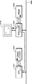
図1は、画像データを表示するための典型的な構成例を概略的に示す。なお、図1では、説明に必要な構成だけを抜き出して示している。バス300に対してCPU(Central Processing Unit)301およびグラフィクス部303が接続される。CPU301に対して、ワークメモリとしてDRAM(Dynamic Random Access Memory)302が接続される。グラフィクス部303に対してVRAM(Video RAM)304が接続される。グラフィクス部303の出力がディスプレイ310に供給される。
FIG. 1 schematically shows a typical configuration example for displaying image data. In FIG. 1, only the components necessary for the description are extracted and shown. A CPU (Central Processing Unit) 301 and a
CPU301は、DRAM302をフレームバッファとして用いて、画像データに対して縮小処理など所定の処理を施す。処理された画像データは、CPU301によりDRAM302から読み出され、バス300を介してグラフィクス部303に供給される。
The
グラフィクス部303は、ディスプレイ310に送る水平および垂直走査周波数を設定して表示解像度を決めると共に、CPU301からの描画命令を実行するグラフィクス制御チップを有する。グラフィクス部303に供給された画像データは、VRAM304に書き込まれる。VRAM304に書き込まれた画像データは、グラフィクス部303によって所定の水平および垂直走査周波数に対応して読み出され、ディジタルビデオ信号としてディスプレイ310に供給される。すなわち、VRAM304がプレーンに相当し、VRAM304の記憶内容がディスプレイ310の表示に直接的に反映される。
The
次に、BD−ROMのHDムービーモードにおけるプレーン構成および各プレーンの合成方法について説明する。なお、以下では、背景技術で説明した動画プレーン、字幕プレーンおよびグラフィクスプレーンを、それぞれビデオプレーン、プレゼンテーショングラフィクスプレーンおよびインタラクティブグラフィクスプレーンと称する。 Next, a plane configuration in the HD movie mode of the BD-ROM and a method for synthesizing each plane will be described. Hereinafter, the moving picture plane, the caption plane, and the graphics plane described in the background art are referred to as a video plane, a presentation graphics plane, and an interactive graphics plane, respectively.
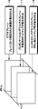
図2は、ビデオプレーン10、プレゼンテーショングラフィクスプレーン11およびインタラクティブグラフィクスプレーン12の一例の構成を示す。ビデオプレーン10は、最も後ろ側(ボトム)に表示され、プレイリストで指定された画像(主に動画データ)が扱われる。プレゼンテーショングラフィクスプレーン11は、ビデオプレーン10の上に表示され、動画再生中に表示される字幕データが扱われる。インタラクティブグラフィクスプレーン12は、最も前面に表示され、GUI(Graphical User Interface)に用いられる部品、例えばメニュー画面を表示するための文字データやボタンを表すビットマップデータといったグラフィクスデータが扱われる。1つの表示画面は、これら3つのプレーンが合成されて表示される。
FIG. 2 shows an exemplary configuration of the
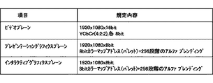
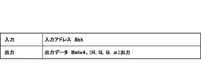
ビデオプレーン10、プレゼンテーショングラフィクスプレーン11およびインタラクティブグラフィクスプレーン12は、それぞれ独立して表示が可能とされ、例えば、図3に一例が示されるような解像度および表示可能色を有する。ビデオプレーン10は、解像度が1920画素×1080ラインで1画素当たりに換算したデータ長が16ビットであって、輝度信号Y、色差信号Cb、Crが4:2:2のシステム(以下、YCbCr(4:2:2))とされる。なお、YCbCr(4:2:2)は、各画素当たり輝度信号Yが8ビット、色差信号Cb、Crがそれぞれ8ビットで、色差信号Cb、Crが水平2画素で一つの色データを構成すると見なすカラーシステムである。
The
プレゼンテーショングラフィクスプレーン11は、1920画素×1080ラインで各画素のサンプリング深さが8ビットとされ、カラーシステムは、256色のパレットを用いた8ビットカラーマップアドレスとされる。
The
インタラクティブグラフィクスプレーン12は、解像度が1920画素×1080ラインで各画素のサンプリング深さが8ビットとされ、カラーシステムは、256色のパレットを用いた8ビットカラーマップアドレスとされる。
The
なお、ビデオプレーン10は、上述以外にも、1280画素×720ライン、720画素×480ラインおよび720画素×576ラインの解像度にもなり得る。その場合には、プレゼンテーショングラフィクスプレーン11およびインタラクティブグラフィクスプレーン12は、ビデオプレーン10と同じ解像度とされる。
In addition to the above, the
また、上述では、プレゼンテーショングラフィクスプレーン11およびインタラクティブグラフィクスプレーン12のカラーシステムを、256色のパレットを用いた8ビットカラーマップアドレスとしたが、これはこの例に限定されない。色数については、サンプリング深さを変えてパレットの色数を増やせばよい。例えばサンプリング深さを12ビットとすれば、パレットで使用可能な色数を4096色とすることができる。また、サンプリング深さを24ビットとして、パレットを持たずに各画素が色情報を持つようにしたYCbCr(4:4:4)およびRGB(4:4:4)も、同様の仕組みで可能である。
In the above description, the color system of the
インタラクティブグラフィクスプレーン12およびプレゼンテーショングラフィクスプレーン11は、256段階のアルファブレンディングが可能とされており、他のプレーンとの合成の際に、不透明度を256段階で設定することが可能とされている。不透明度の設定は、画素毎に行うことができる。以下では、不透明度αが(0≦α≦1)の範囲で表され、不透明度α=0で完全に透明、不透明度α=1で完全に不透明であるものとする。
The
プレゼンテーショングラフィクスプレーン11では、例えばPNG(Portable Network Graphics)形式の画像データが扱われる。また、インタラクティブグラフィクスプレーン12でも、PNG形式の画像データを扱うことができる。PNG形式は、1画素のサンプリング深さが1ビット〜16ビットとされ、サンプリング深さが8ビットまたは16ビットの場合に、アルファチャンネル、すなわち、それぞれの画素成分の不透明度情報(アルファデータと称する)を付加することができる。サンプリング深さが8ビットの場合には、256段階で不透明度を指定することができる。このアルファチャンネルによる不透明度情報を用いてアルファブレンディングが行われる。また、256色までのパレットイメージを用いることができ、予め用意されたパレットの何番目の要素(インデックス)であるかがインデックス番号により表現される。
The
なお、プレゼンテーショングラフィクスプレーン11およびインタラクティブグラフィクスプレーン12で扱われる画像データは、PNG形式に限定されない。JPEG方式など他の圧縮符号化方式で圧縮符号化された画像データや、ランレングス圧縮された画像データ、圧縮符号化がなされていないビットマップデータなどを扱うようにしてもよい。
Note that the image data handled by the
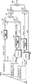
図4は、上述の図2および図3に従い3つのプレーンを合成する一例の構成を示す。ビデオプレーン10の動画データが422/444変換回路20に供給される。動画データは、422/444変換回路20でカラーシステムがYCbCr(4:2:2)からYCbCr(4:4:4)に変換され、乗算器21に入力される。なお、422/444変換回路20と乗算器21との間に解像度変換回路を挿入し、動画データの解像度を変換するようにしてもよい。
FIG. 4 shows an example configuration for synthesizing three planes according to FIGS. 2 and 3 described above. The moving image data of the
プレゼンテーショングラフィクスプレーン11の画像データがパレット22に入力され、RGB(4:4:4)の画像データとして出力される。この画像データに対してアルファブレンディングによる不透明度が指定されている場合には、指定された不透明度α1(0≦α1≦1)がパレット22から出力される。
Image data of the
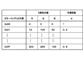
図5は、パレット22の入出力データの一例を示す。パレット22は、例えばPNG形式のファイルに対応したパレット情報がテーブルとして格納される。パレット22は、入力された8ビットの画素データをアドレスとして、インデックス番号が参照される。このインデックス番号に基づき、それぞれ8ビットのデータからなるRGB(4:4:4)のデータが出力される。それと共に、パレット22では、不透明度を表すアルファチャンネルのデータが取り出される。
FIG. 5 shows an example of input / output data of the
図6は、パレット22に格納される一例のパレットテーブルを示す。256個のカラーインデックス値〔0x00〕〜〔0xFF〕(〔0x〕は16進表記であることを示す)のそれぞれに対して、各々8ビットで表現される三原色の値R、GおよびBと、不透明度αとが割り当てられる。パレット22は、入力されたPNG形式の画像データに基づきパレットテーブルが参照され、画像データにより指定されたインデックス値に対応する、それぞれ8ビットのデータからなるR、GおよびB各色のデータ(RGBデータ)と、不透明度αとを画素毎に出力する。後述するパレット26にも、同様のパレットテーブルが格納される。
FIG. 6 shows an example pallet table stored in the
パレット22から出力されたRGBデータは、RGB/YCbCr変換回路30に供給され、各データ長が8ビットの輝度信号Yと色信号Cb、Crのデータに変換される(以下、まとめてYCbCrデータと称する)。これは、以降のプレーン間合成を共通のデータ形式で行う必要があるためで、動画データのデータ形式であるYCbCrデータに統一している。
The RGB data output from the
RGB/YCbCr変換回路30から出力されたYCbCrデータおよび不透明度データα1とがそれぞれ乗算器23に入力される。なお、RGB/YCbCr変換回路30と乗算器23との間に解像度変換回路を挿入し、YCbCrデータの解像度を変換するようにしてもよい。乗算器23では、入力されたYCbCrデータに不透明度データα1が乗ぜられる。乗算結果は、加算器24の一方の入力端に入力される。なお、乗算器23では、YCbCrデータにおける輝度信号Y、色差信号Cb、Crのそれぞれについて、不透明度データα1との乗算が行われる。また、不透明度データα1の補数(1−α1)が乗算器21に供給される。
The YCbCr data and the opacity data α1 output from the RGB /
乗算器21では、422/444変換回路20から入力された動画データに不透明度データα1の補数(1−α1)が乗ぜられる。乗算結果は、加算器24の他方の入力端に入力される。加算器24において、乗算器21および23の乗算結果が加算される。これにより、ビデオプレーン10とプレゼンテーショングラフィクスプレーン11とが合成される。加算器24の加算結果が乗算器25に入力される。
In the
インタラクティブグラフィクスプレーン12の画像データもプレゼンテーショングラフィクスプレーン11と同様に、パレット26によりRGB(4:4:4)のデータが出力され、RGB/YCbCr変換回路27に入力される。グラフィクスプレーン12の画像データのカラーシステムがRGB(4:4:4)である場合には、カラーシステムがYCbCr(4:4:4)に変換されてRGB/YCbCr変換回路27から出力される。RGB/YCbCr変換回路27から出力されたYCbCrデータが乗算器28に入力される。なお、RGB/YCbCr変換回路27と乗算器28との間に解像度変換回路を挿入し、YCbCrデータの解像度を変換するようにしてもよい。
Similarly to the
パレット26において、インデックス値に対してアルファブレンディングによる不透明度が指定されている場合には、指定された不透明度α2(0≦α2≦1)がパレット26から出力される。不透明度データα2は、乗算器28に供給される。乗算器28では、RGB/YCbCr変換回路27から入力されたYCbCrデータに対し、輝度信号Y、色差信号Cb、Crのそれぞれについて、不透明度データα2との乗算が行われる。乗算器28による乗算結果が加算器29の一方の入力端に入力される。また、不透明度データα2の補数(1−α2)が乗算器25に供給される。
In the
乗算器25では、加算器24の加算結果に対して不透明度データα2の補数(1−α2)が乗ぜられる。乗算器25の乗算結果は、加算器29の他方の入力端に入力され、上述した乗算器28による乗算結果と加算される。これにより、ビデオプレーン10とプレゼンテーショングラフィクスプレーン11との合成結果に対して、さらに、インタラクティブグラフィクスプレーン12が合成される。
In the
プレゼンテーショングラフィクスプレーン11およびインタラクティブグラフィクスプレーン12において、例えば、表示すべき画像の無い領域の不透明度α=0と設定することで、そのプレーンの下に表示されるプレーンを透過表示させることができ、例えばビデオプレーン10に表示されている動画データを、プレゼンテーショングラフィクスプレーン11やインタラクティブグラフィクスプレーン12の背景として表示することができる。
In the
なお、パレット22とRGB/YCbCr変換回路30とをパレット22’として一つにまとめ、パレット22’から直接的にYCbCrデータが出力されるようにしてもよい。
Alternatively, the
この図4に示される構成は、ハードウェアおよびソフトウェアの何れでも実現可能なものである。 The configuration shown in FIG. 4 can be realized by either hardware or software.
以上のような構成をとることで、再生専用の規格に必要な、メニュー画面とボタンの表示を可能としている。メニュー画面上のボタンを選択することで、そのボタンに対応付けられたプレイリストを再生させるようにできる。また、再生専用規格で必要な、動画の上に字幕を重ねて表示する機能が実現される。 By adopting the above configuration, it is possible to display menu screens and buttons necessary for a reproduction-only standard. By selecting a button on the menu screen, a play list associated with the button can be reproduced. In addition, a function for displaying subtitles superimposed on a moving image, which is necessary for the reproduction-only standard, is realized.
上述したプレーン合成の構成は、ビデオプレーン10が1枚しかないので、ピクチャインピクチャのような、2本の動画データを並列的に扱い、2本のビデオ信号による2つの画面を合成して同時に表示することが想定されておらず、このままの構成でこれを実現することが困難である。
In the above-described plane composition configuration, since there is only one
次に、この発明の実施の第1および第2の形態について説明する。この発明は、上述したBD−ROMのHDムービーモードを拡張し、より高機能なグラフィクス描画と、ユーザとの双方向性実現とに適したフォーマットを提供することを最終的な目的とする。 Next, first and second embodiments of the present invention will be described. The final object of the present invention is to extend the above-described HD movie mode of the BD-ROM to provide a format suitable for drawing more sophisticated graphics and realizing interactivity with the user.
なお、BD−ROMのHDムービーモードを拡張した規格を、フルプロファイルと称する。フルプロファイルは、更なるBD−ROMの高機能化を目指して、より複雑な双方向性や、ネットワーク通信への対応の実現を図るものである。 A standard that expands the HD movie mode of the BD-ROM is referred to as a full profile. The full profile aims to realize more complex bidirectionality and network communication with the aim of further enhancing the functionality of the BD-ROM.
フルプロファイルにおいて必要とされ、BD−ROMのHDムービーモードで実現されていない機能のうち、プレーン構成に関するものは、次の3つが挙げられる。
(1)ピクチャインピクチャ機能。
(2)動画データを縮小し、表示領域中の任意の位置へ表示させる。
(3)(2)の縮小表示の際の縮小表示された動画データ以外の部分(背景)に対して壁紙を表示させる。
Of the functions that are required in the full profile and are not realized in the HD movie mode of the BD-ROM, the following three are related to the plane configuration.
(1) Picture-in-picture function.
(2) The moving image data is reduced and displayed at an arbitrary position in the display area.
(3) The wallpaper is displayed on a portion (background) other than the reduced moving image data in the reduced display of (2).
なお、「壁紙」とは、ディスプレイ上に表示されるオブジェクトの背景に、例えばディスプレイの表示可能領域を埋め尽くすように画像を表示することを指し、比較的小さな画像をタイル状に繰り返し表示させて構成することが多い。勿論、これに限らず、表示可能領域に対応するサイズの画像を1枚だけ表示して壁紙とすることもできるし、単色やグラデーションを壁紙として表示させることもできる。また、壁紙は、必ずしも表示可能領域を埋め尽くしていなくてもよい。 “Wallpaper” refers to displaying an image on the background of an object displayed on the display so as to fill the displayable area of the display, for example, and a relatively small image is repeatedly displayed in a tile shape. Often configured. Of course, the present invention is not limited to this, and only one image having a size corresponding to the displayable area can be displayed as a wallpaper, or a single color or gradation can be displayed as a wallpaper. The wallpaper does not necessarily fill the displayable area.
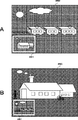
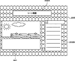
ここで、(1)の、ピクチャインピクチャについて、図7を用いて説明する。ピクチャインピクチャは、映像を再生中に、再生映像画面内に小さな表示領域を設けるなどして、他の映像を並列的に表示する機能である。このとき、大きく表示された一方の映像の上に重なるように、もう一方の映像が表示されることが多い。大きく表示された映像画面を親画面と称し、親画面中に重ねて表示される小領域の画面を子画面と称する。図7Aでは、親画面250中に子画面251が表示されている。なお、図7中、子画面251の周囲の白枠は、図を見易くするためのものであって、実際に表示するか否か、また枠を表示する際にどのような枠にするかは、任意である。
Here, the picture-in-picture (1) will be described with reference to FIG. Picture-in-picture is a function for displaying other videos in parallel by providing a small display area in the playback video screen during playback of the video. At this time, in many cases, the other video is displayed so as to be superimposed on the one of the larger video. A video screen displayed in a large size is referred to as a parent screen, and a small area screen displayed in an overlapping manner on the parent screen is referred to as a child screen. In FIG. 7A, a
子画面251は、親画面250の上に乗っているように重ねられて表示され、子画面251の領域では、親画面250が見えなくなっている。このとき、子画面251に対してアルファブレンディング処理を行わなくても、ピクチャインピクチャの機能上、問題はない。また、ピクチャインピクチャ機能では、親画面250および子画面251の表示内容は、図7Aおよび図7Bにそれぞれ示されるように、互いに切り替えられることが求められる。さらに、子画面251は、位置およびサイズを変更できるようにすると、ユーザにとって利便性が高くなり、より好ましい。
The
先ず、この発明の実施の第1の形態について説明する。この発明の実施の第1の形態では、上述した(1)のピクチャインピクチャ、(2)の縮小画像表示、(3)の壁紙画像表示を実現するために、図2を用いて説明したBD−ROMのHDムービーモードにおけるプレーン構成に対して、さらに1枚、プレーンを追加する。以下、追加するプレーンを、第2ビデオプレーンと称する。第2ビデオプレーンは、ビデオプレーンよりさらに奥に配置される。すなわち、この実施の第1の形態では、プレーンは、奥から、第2ビデオプレーン、ビデオプレーン、プレゼンテーショングラフィクスプレーン、インタラクティブグラフィクスプレーンの順に配置される。ビデオプレーンおよび第2ビデオプレーンを用いて親画面250および子画面251の表示を実現する。
First, a first embodiment of the present invention will be described. In the first embodiment of the present invention, the BD described with reference to FIG. 2 in order to realize the picture-in-picture of (1), the reduced image display of (2), and the wallpaper image display of (3) described above. -One more plane is added to the plane configuration in the HD movie mode of the ROM. Hereinafter, the plane to be added is referred to as a second video plane. The second video plane is disposed deeper than the video plane. That is, in the first embodiment, the planes are arranged from the back in the order of the second video plane, the video plane, the presentation graphics plane, and the interactive graphics plane. The
図8は、第2ビデオプレーン50、ビデオプレーン10、プレゼンテーショングラフィクスプレーン11およびインタラクティブグラフィクスプレーン12を合成するための一例の構成を示す。なお、この図8において、上述した図4と共通する部分には同一の符号を付し、詳細な説明を省略する。
FIG. 8 shows an exemplary configuration for synthesizing the
上述したように、親画面250および子画面251の間では、アルファ合成が不要であるので、親画面250および子画面251は、各画素について何れかが表示されればよいことになる。したがって、親画面250および子画面251を表示するビデオプレーン10および第2ビデオプレーン50の間では、何方のプレーンを表示するかを画素単位に切り替えることができればよい。
As described above, since alpha synthesis is not required between the
そこで、図8に示されるように、ビデオプレーン10と第2ビデオプレーン50の出力を切り替えるスイッチ51を設ける。このスイッチ51は、画素単位で入力端51Aおよび51Bを切り替えることができるように制御される。例えば、上述の図1におけるグラフィック部303のタイミング信号により、スイッチ51の切り替えタイミングが制御される。タイミング信号は、CPU301により制御することができる。CPU301がタイミング制御を行うようにもできる。スイッチ51の出力は、422/444変換回路20に供給される。
Therefore, as shown in FIG. 8, a switch 51 for switching the output of the
ピクチャインピクチャ機能を実行する際には、子画面251を表示するための動画データは、予め縮小処理を施してからビデオプレーン10または第2ビデオプレーン50に格納する。親画面250の内容と子画面251の内容とを入れ替える際には、ビデオプレーン10および第2ビデオプレーン50の内容を一旦クリアして、新たな動画データを再描画する。
When executing the picture-in-picture function, the moving image data for displaying the
なお、第2ビデオプレーン50の解像度や表示可能色数などは、ビデオプレーン10と同一とするとよい。これに限らず、ピクチャインピクチャの機能に制限がある場合、例えば、第2ビデオプレーン50を子画面251の表示に限定して使用するような場合、第2ビデオプレーン50の解像度は、子画面251の解像度を満たしていれば十分である。
The resolution and the number of displayable colors of the
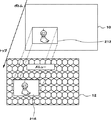
この発明の実施の第1の形態によれば、第2ビデオプレーン50を利用することで、壁紙表示を実現することができる。図9は、第2ビデオプレーン50を利用して壁紙画像200の表示を実現した例を示す。図9の例では、動画201、ならびに、GUIの部品202Aおよび202Bが壁紙画像200を背景として表示される様子が示される。
According to the first embodiment of the present invention, wallpaper display can be realized by using the
壁紙画像200は、少なくとも下記の3条件を満たしている必要がある。
(1)各プレーンの表示に対して最も奥に表示される。
(2)ビデオプレーン10上に表示される動画201のサイズ変更に応じて、背景を隙間無く埋め尽くして表示される。
(3)インタラクティブグラフィクスプレーン12に表示されるGUIの部品の背景として表示される。
The
(1) Displayed at the back of each plane display.
(2) In accordance with the size change of the moving
(3) Displayed as the background of a GUI component displayed on the
第2ビデオプレーン50を利用して壁紙画像200を表示させることで、これら3条件を満たすことができる。
By displaying the
図8を用いて説明したように、ビデオプレーン10または第2ビデオプレーン50に対してプレゼンテーショングラフィクスプレーン11が合成され、その合成画像に対してインタラクティブグラフィクスプレーン12がさらに合成される。そのため、プレゼンテーショングラフィクスプレーン11やインタラクティブグラフィクスプレーン12に対して所定に不透明度を設定することで、図8において当該プレーンより後ろに配置されたプレーンの表示を隠したり、透過させたりすることができる。これにより、インタラクティブグラフィクスプレーン12に表示される部品202Aおよび202Bの背景に壁紙画像200を表示させることができる。換言すれば、壁紙画像200を、プレゼンテーショングラフィクスプレーン11およびインタラクティブグラフィクスプレーン12に対して奥に表示させることができる。
As described with reference to FIG. 8, the
ビデオプレーン10および第2ビデオプレーン50は、スイッチ51により画素単位で切り替えられるため、ビデオプレーン10の表示領域と第2ビデオプレーン50の表示領域とは、排他的な関係にある。そのため、ビデオプレーン10に表示される動画201のサイズの変更に応じて、第2ビデオプレーン50上の壁紙画像200を隙間無く表示させることが可能である。また、これにより、ビデオプレーン10上の動画201が、第2ビデオプレーン50に表示される壁紙画像200を背景として表示されているように見せることができる。したがって、プレーン全体として、第2ビデオプレーン50上の壁紙画像200が最も奥に表示されているようにできる。
Since the
なお、上述では、スイッチ50を画素単位で切り替えるようにしているが、これは、1画素単位に限られず、2画素単位、4画素単位など、複数画素単位でスイッチ50を切り替えるようにしてもよい。
In the above description, the
次に、この発明の実施の第2の形態について説明する。この実施の第2の形態では、上述した図4の構成に対して新たにプレーンを追加することなく、ピクチャインピクチャや背景の壁紙画像の表示を実現するものである。 Next, a second embodiment of the present invention will be described. In the second embodiment, display of a picture-in-picture or background wallpaper image is realized without adding a new plane to the configuration of FIG. 4 described above.
先ず、壁紙画像の表示の実現方法について説明する。なお、この実施の第2の形態では、プレーン構成は、図2を用いて説明したBD−ROMのHDムービーモードの場合と同様に、奥からビデオプレーン10、プレゼンテーショングラフィクスプレーン11およびインタラクティブグラフィクスプレーン12の順となっており、各プレーンを合成するための構成は、図4と同一の構成を用いるものとする。
First, a method for realizing wallpaper image display will be described. In the second embodiment, the plane configuration is the same as in the BD-ROM HD movie mode described with reference to FIG. 2, from the back, the
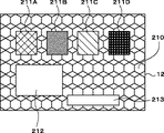
図10を用いて説明する。この図10の例では、壁紙画像210を背景として、インタラクティブグラフィクスプレーン12上の複数のボタン画像、すなわちGUIに用いられる部品211A、211B、211Cおよび211Dが表示されると共に、ビデオプレーン10上の動画が領域212に、プレゼンテーショングラフィクスプレーン11上の例えば字幕データが領域213にそれぞれ表示される。また、部品211A、211B、211Cおよび211D、領域212、ならびに、領域213以外の部分には、壁紙画像210が表示されている。
This will be described with reference to FIG. In the example of FIG. 10, a plurality of button images on the
このような表示を実現する場合、最前面のインタラクティブグラフィクスプレーン12において、領域212および213の不透明度α2を0として、インタラクティブグラフィクスプレーン12の奥にある2枚のプレーンが完全に見えるようにする。領域212および213以外の領域は、不透明度α2を例えば1として、壁紙画像210を表示すると共に、部品211A、211B、211Cおよび211Dをそれぞれ表示する。なお、壁紙画像210は、領域212および213、ならびに、部品211A、211B、211Cおよび211Dを除いた領域に描画される。
When such display is realized, the opacity α2 of the
プレゼンテーショングラフィクスプレーン11では、領域212の不透明度α1を0として、プレゼンテーショングラフィクスプレーン11の奥にあるビデオプレーン10が完全に見えるようにする。領域212以外の領域は、不透明度α1を例えば1とする。これに限らず、プレゼンテーショングラフィクスプレーン11において、字幕データが表示される領域213の不透明度α1を1とし、その他の領域の不透明度α1を0としてもよい。
In the
ビデオプレーン10では、図11に一例が示されるように、領域212に収まるように動画のサイズを縮小した縮小画像データ216を作成し、且つ、縮小画像データ216を領域212の位置に表示されるように配置する。こうすることによって、図2および図4に示される構成に対して、新たなプレーンを追加することなく、壁紙画像210の表示を実現することができる。
In the
なお、壁紙画像210を描画する領域を求めるアルゴリズムやプログラムについては、プログラミング言語のライブラリとして提供されている場合が多く、通常は、制作者側で特に意識する必要は無い。
Note that algorithms and programs for obtaining an area for drawing the
また、この実施の第2の形態では、上述のように、壁紙画像210を描画する際には、領域212および213、ならびに、部品211A、211B、211Cおよび211Dを除いた領域を求める必要があり、壁紙画像210の描画に際して、計算量の多い処理が必要とされる。そのため、特に時間の経過に伴ってインタラクティブグラフィクスプレーン12上を移動したり、変形したりするGUI部品などがある場合、計算量の増加に伴う動作速度の低下が発生する可能性があるため、このようなGUI部品を用いる場合、この点を考慮するのが好ましい。
Further, in the second embodiment, as described above, when the
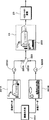
次に、この実施の第2の形態によるピクチャインピクチャの実現方法について説明する。図12は、1枚のビデオプレーン10を用いてピクチャインピクチャを実現するための一例の構成を概略的に示す。図12に示されるように、この実施の第2の形態では、画像出力部220とビデオプレーン10との間に2つのフレームバッファ221Aおよび221Bを設ける。
Next, a method for realizing a picture-in-picture according to the second embodiment will be described. FIG. 12 schematically illustrates an example configuration for realizing picture-in-picture using one
フレームバッファ221Aの出力は、ダウンコンバータ222Aを介してスイッチ223の入力端223Aに供給される。フレームバッファ221Bの出力は、ダウンコンバータ222Bを介してスイッチ223の入力端223Bに供給される。スイッチ233は、画素単位で入力端223Aおよび223Bを切り替えることができるようにされている。スイッチ223の出力は、ビデオプレーン10に供給される。
The output of the
なお、フレームバッファ221Aおよび221Bは、ディスプレイに表示される画像と1対1に対応する画像データを保持するプレーンメモリ(例えばVRAM304)ではなく、CPUが有するメインメモリの一部や、ビデオデコーダの後段に設けられるフレームバッファである。上述の図1においては、例えばDRAM302に対応するものである。
Note that the
画像出力部220は、異なる2本のビデオストリーム(ビデオストリームA、ビデオストリームBとする)を処理可能とされており、画像データ出力部220から出力されたビデオストリームAおよびビデオストリームBは、フレームバッファ221Aおよび221Bにそれぞれ供給される。以下では、ビデオストリームAを親画面とし、ビデオストリームBをビデオストリームAの子画面230として表示させるものとする。
The
フレームバッファ221Bから読み出された画像データは、ダウンコンバータ222Bに供給され、サイズの変更がなされる。ダウンコンバータ222Bでは、例えば画素の間引き処理や補間処理を行うことにより、画像データのサイズを縮小する。ダウンコンバータ222Bでサイズが縮小された縮小画像データは、スイッチ223の入力端223Bに供給される。
The image data read from the
一方、フレームバッファ221Aから読み出された画像データは、ダウンコンバータ222Aを素通りしてスイッチ223の入力端223Aに供給される。なお、ダウンコンバータ222Aも、ダウンコンバータ222Bと同様、入力された画像データのサイズを縮小する。
On the other hand, the image data read from the
スイッチ223では、例えばビデオプレーン10に対して、表示領域の上端から順に、ライン毎に左から右へと走査しながら表示領域の下端まで、画素単位で行われる画像データの転送に連動して、入力端223Aと223Bとが所定にタイミング制御されて切り替えられる。図12の例の場合、子画面230を表示させたい位置の画素を書き込む際に、スイッチ223において入力端223Bを選択するように切り替えることで、ビデオプレーン10の一部に、フレームバッファ221Bから読み出された動画データが子画面230として描画される。
In the
スイッチ223の切り替えタイミングの例について、図13を用いて説明する。なお、図13では、繁雑さを避けるために、図13Bに示されるように、画面(1フレーム)の解像度を20画素×10ラインと簡略化している。図13Aに示されるような位置に子画面230が表示される例を考える。図13Cは、このときのスイッチ223の一例の切り替えタイミングを示す。図13Cにおいて、バッファA側がフレームバッファ221Aすなわち入力端223A側を示し、バッファB側がフレームバッファ221Bすなわち入力端223B側を示す。このように、子画面230が掛からないラインでは、入力端223A側が選択され、子画面230が掛かるラインでは、ライン内で子画面230が掛からない画素のタイミングでは入力端223Aが選択され、子画面230が掛かる画素のタイミングにおいて入力端223B側が選択される。このようにスイッチ223の切り替えタイミングを画素単位で制御することで、1枚のビデオプレーン10を用いて親画面と子画面230とを並列的に表示させることが可能とされる。
An example of switching timing of the
なお、このスイッチの切り替えタイミング制御は、上述したこの発明の実施の第1の形態における、ビデオプレーン10および第2ビデオプレーン50による子画面表示制御の際にも適用できる。
The switch switching timing control can also be applied to the small-screen display control by the
また、ここでは子画面230の形状を長方形としたが、上述のような画素単位でのスイッチ223の切り替え制御によれば、子画面230の形状を長方形以外の任意の形状とすることができる。
In addition, although the shape of the
子画面230の表示内容と親画面の表示内容とを入れ替える際の処理について、概略的に説明する。この場合、フレームバッファ221Bから読み出された画像データは、ダウンコンバータ222Bを素通りしてスイッチ223の入力端223Bに供給される。一方、フレームバッファ221Aから読み出された画像データは、ダウンコンバータ222Aで縮小処理され、スイッチ223の入力端223Aに供給される。図13Dに一例が示されるように、子画面230の内容と親画面の内容とを入れ替える指示がタイミングTでなされた場合、タイミングTにおいて、スイッチ223による選択方向が入力端223Aと入力端223Bとで入れ替えられる。
A process for switching the display contents of the
図13Dのようにスイッチ223の切り替え制御を行うと、タイミングTに対応する画素から以降で、子画面230の内容と親画面の内容とが入れ替えられる。切り替えタイミングは、これに限らず、例えば、タイミングTで子画面および親画面の入れ替え指示があった場合に、当該フレームの終端または次フレームの先頭、あるいは、フレーム終端および次フレームの先端の間まで、スイッチ223の選択タイミングの入れ替えを待つようにしてもよい。この場合には、子画面および親画面の入れ替え指示があった次のフレームから、子画面230の内容と親画面の内容とが入れ替わった表示がなされる。
When the switching control of the
なお、上述では、子画面230の内容と親画面の内容との入れ替えを、スイッチ223の切り替え制御によって行っていたが、これはこの例に限定されない。例えば、フレームバッファ221Aおよび221Bのうち一方を子画面230専用とし、画像出力部220からの出力先をフレームバッファ221Aおよび221Bとで切り替えるようにしてもよい。この場合には、親画面と子画面との入れ替えの際に、スイッチ223の選択タイミングを入れ替える必要が無い。
In the above description, the contents of the
また、上述では、スイッチ223の切り替えタイミングを画素単位で制御しているが、これは、1画素単位に限られず、2画素単位、4画素単位など、複数画素単位でスイッチ223を切り替えるようにしてもよい。
In the above description, the switching timing of the
さらに、上述では、フレームバッファ221Aおよび221Bからビデオプレーン10に対して、ライン毎に走査して画像データを転送しているが、これはこの例に限定されない。例えば、フレームバッファ221Aおよび221Bから、所定の領域からなるブロック単位で画像データを読み出し、ビデオプレーン10に転送することも可能である。この場合、スイッチ223も、ブロック単位で切り替えタイミングが制御される。
Furthermore, in the above description, image data is transferred by scanning line by line from the
この発明の実施の第1の形態のように、プレーンを増やすことは、プレーン専用のメモリ(VRAM304など)およびプレーンメモリにアクセスするためのハードウェアが必要となる。そのため、プレーンを増やす方法は、CPUの処理速度は高速ではないが、ハードウェアの拡張性の点で制限が緩いシステムに適しているといえる。例えば、BD−ROMの再生専用機がこれに相当する。 As in the first embodiment of the present invention, increasing the number of planes requires a plane-dedicated memory (such as VRAM 304) and hardware for accessing the plane memory. Therefore, it can be said that the method of increasing the number of planes is suitable for a system in which the processing speed of the CPU is not high, but the restriction is loose in terms of hardware expandability. For example, a BD-ROM reproduction-only machine corresponds to this.
一方、CPUの処理速度が非常に高速で、さらにグラフィクスの高速描画を専用的に行うLSI(Large-Scale Integration)を搭載しているようなシステムの場合、ハードウェア(特にグラフィクス描画に関連したハードウェア)がカスタム化されている傾向が強く、ハードウェアの拡張が難しい。このようなシステムの場合、プレーンを増やすよりも、この発明の実施の第2の形態のように、GUIで用いられる各部品の位置、サイズ、合成の順序を計算した後、全てを1つのプレーンに描画する方法が適しているといえる。例えば、汎用のコンピュータ装置などでBD−ROMを再生するような場合がこれに相当する。 On the other hand, in the case of a system with a very high CPU processing speed and LSI (Large-Scale Integration) dedicated to high-speed graphics rendering, hardware (especially hardware related to graphics rendering) Hardware) tends to be customized, and hardware expansion is difficult. In such a system, rather than increasing the number of planes, as in the second embodiment of the present invention, after calculating the position, size, and composition order of each component used in the GUI, all of them are combined into one plane. It can be said that the drawing method is suitable. For example, this corresponds to a case where a BD-ROM is reproduced by a general-purpose computer device or the like.
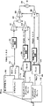
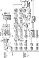
次に、上述の実施の第1の形態および第2の形態にそれぞれ適用可能なプレーヤデコーダ100について説明する。図14は、この発明の実施の第1の形態に適用可能なプレーヤデコーダ100の一例の構成を示す機能ブロック図である。なお、このプレーヤデコーダ100は、この発明の実施の第2の形態にも略同様の構成で適用可能である。プレーヤデコーダ100を実施の第2の形態に適用する場合の構成については、適宜、説明する。
Next, the
このプレーヤデコーダ100は、図示されないドライブ装置に装填されたディスクから再生されたデータを解釈し、AV(Audio/Video)ストリームを出力すると共に、出力されたAVストリームに対するユーザによるインタラクティブな操作を可能とする。
The
なお、プレーヤデコーダ100は、図示されないCPUにより全体の動作が制御される。例えば、プレーヤデコーダ100の各部におけるストリームやデータの流れは、CPUにより監視され、制御される。
The overall operation of the
図示されないドライブ装置にディスクが装填されると、BD−ROMのHDムービーモードにおいては、先ず、プレイリストの再生順序を指定したファイル(例えばファイル名を「scenario.hdmv」とする)と、メニューやタイトルを構成するプレイリスト群の先頭プレイリストを指すファイル(例えばファイル名を「entrylist.data」とする)とが再生され、このファイル「scenario.hdmv」およびファイル「entrylist.data」の記述に基づき、必要な他のファイルが読み出され、ディスクに記録されたコンテンツが再生される。 When a disc is loaded in a drive device (not shown), in the HD movie mode of the BD-ROM, first, a file that specifies the playback order of the playlist (for example, the file name is “scenario.hdmv”), a menu, A file that points to the first playlist in the playlist group constituting the title (for example, the file name is “entrylist.data”) is played back, and based on the description of the file “scenario.hdmv” and the file “entrylist.data” Other necessary files are read and the content recorded on the disc is reproduced.
例えば、ファイル「scenario.hdmv」およびファイル「entrylist.data」の記述に基づき、ビデオプレーン10や第2ビデオプレーン50に表示するための動画データ、プレゼンテーショングラフィクスプレーン11やインタラクティブグラフィクスプレーン12、第2ビデオプレーン50に表示するための画像データ、プレイリストファイルなどがディスクから読み出される。フルプロファイルにおいては、プログラムを格納したファイルが読み出され、実行される。
For example, based on the description of the file “scenario.hdmv” and the file “entrylist.data”, moving image data to be displayed on the
以下では、ディスクから読み出されるこれらのデータのうち、動画データ、サブピクチャ(字幕データ)や音声データといった、連続的に処理する必要があるストリームをリアルタイムストリームと称する。また、シナリオファイル、プレイリストファイル、スクリプトファイルおよびプログラムファイル、ならびに、一部の動画、静止画およびサウンドデータといった、連続的な処理を要求されない非リアルタイムなデータを、ストアオブジェクトと称する。ストアオブジェクトは、メモリ上などに蓄積、展開され、必要に応じて処理される。 Hereinafter, among these data read from the disc, a stream that needs to be continuously processed, such as moving image data, sub-picture (caption data), and audio data, is referred to as a real-time stream. Non-real-time data that does not require continuous processing, such as scenario files, playlist files, script files and program files, and some moving images, still images, and sound data are referred to as store objects. Store objects are stored and expanded on a memory or the like and processed as necessary.
プレーヤデコーダ100は、チャンネル(1)および(2)の2系統の入力チャンネルを有し、入力チャンネル(1)の入力端101に、ストアオブジェクトが入力される。入力チャンネル(2)の入力端202に、リアルタイムストリームが入力される。入力端202に、ストアオブジェクトを入力することも可能である。この実施の第1および第2の形態では、入力端202に入力されるリアルタイムストリームおよび一部のストアオブジェクトは、例えばMPEG2 TS(Moving Pictures Experts Group 2 Transport Stream)である。
The
なお、入力端202に入力されるリアルタイムストリームは、MPEG2 TSに限られない。パケット単位で伝送され、ビデオデータ、オーディオデータ、静止画像データなどを多重化可能であれば、他の形式のストリームを入力するようにしてもよい。このときには、後述するPIDフィルタ110は、そのストリーム形式に適合したデマルチプレクサとして用いられ、ビデオデータ、オーディオデータ、静止画像データなどを分離する。
Note that the real-time stream input to the
また、例えば、ドライブ装置においてディスクの回転速度を2倍速などの高速回転としてディスクからの読み出し転送レートを上げ、時分割で動作させることにより、ディスクからの、チャンネル(1)および(2)の2系統の読み出しが実現可能である。 Further, for example, by rotating the disk at a high speed such as double speed in the drive device to increase the read transfer rate from the disk and operating in a time-sharing manner, channels (1) and (2) 2 from the disk are operated. System readout can be realized.
先ず、入力チャンネル(1)の系統について説明する。入力端101に入力されたストアオブジェクトは、スイッチ回路102に入力される。ストアオブジェクトとしてECMA(European Computer Manufacturers Association)スクリプトやHTML(Hyper Text Markup Language)ファイル(またはXHTMLファイル)、Javaファイルなどによるプログラムコードが入力された場合、スイッチ回路102において出力端102Aが選択され、入力されたプログラムコードがコードバッファ104に蓄えられる。
First, the system of the input channel (1) will be described. The store object input to the
一方、ストアオブジェクトとして画像データが入力された場合、スイッチ回路102において出力端102Bが選択され、入力された画像データがスイッチ回路103に入力される。入力端202に入力されたリアルタイムストリームに、プレゼンテーショングラフィクスプレーン11やインタラクティブグラフィクスプレーン12に表示するための画像データが含まれていない場合には、スイッチ回路103で入力端103Aが選択され、スイッチ回路102から入力された画像データがコンテンツバッファ105に蓄えられる。
On the other hand, when image data is input as a store object, the output terminal 102 B is selected in the
同様にして、入力端202に入力されたリアルタイムストリームに、プレゼンテーショングラフィクスプレーン11やインタラクティブグラフィクスプレーン12に表示するための画像データが含まれている場合には、スイッチ回路103において入力端103Bが選択され、当該画像データがコンテンツバッファ105に蓄えられる。コードバッファ104およびコンテンツバッファ105に蓄えられたストアオブジェクトは、必要に応じて読み出され、マルチメディアエンジン106に供給される。
Similarly, when the real-time stream input to the
コンテンツバッファ105に蓄えられたストアオブジェクトのうち画像データは、スイッチ回路107および108をそれぞれ介して、グラフィクスデコーダA116およびグラフィクスデコーダB117にも供給される。
Of the store objects stored in the
マルチメディアエンジン106は、XMLパーサ106A、プログラム/スクリプトインタプリタ106Bおよびグラフィクスレンダラ106Cを含む。マルチメディアエンジン106は、さらに、サウンドプレーヤ106Dを有し、オーディオデータの扱いを可能としている。マルチメディアエンジン106は、独立的なハードウェアで構成してもよいし、上述した図示されないCPUの、所定のプログラムに基づく処理で実現することも可能である。
The
XMLパーサ106Aは、XML(Extensible Markup Language)文書を解析する機能を有し、HTML文書やXHTML文書の解析も可能である。XMLパーサ106Aで解釈されたHTML文書やXHTML文書は、このプレーヤデコーダ100で実行可能な形式に変換される。プログラム/スクリプトインタプリタ106Bは、Java(登録商標)プログラムやECMAスクリプト等を解析し、このプレーヤデコーダ100で実行可能な形式に変換される。また、グラフィクスレンダラ106Cは、画像データを字幕プレーン11およびグラフィクスプレーン12に展開可能な形式にデコードする。
The
マルチメディアエンジン106において、バッファ109をワークメモリとして、これらXMLパーサ106A、プログラム/スクリプトインタプリタ106Bおよびグラフィクスレンダラ106Cの処理が行われる。例えば、XMLパーサ106Aおよびプログラム/スクリプトインタプリタ106Bにより、バッファ109のうちコードバッファ109Aが用いられる。また、グラフィクスレンダラ106Cにより、バッファ109のうちグラフィクスバッファ109Dが用いられる。バッファ109は、上述のコードバッファ109Aおよびグラフィクスバッファ109Dの他に、文字列の表示に用いるフォントデータが格納されるフォントバッファ109B、XMLパーサ106AでHTML文書を解析した結果を階層化された木構造で保持するためのツリーバッファ109C、サウンドプレーヤ106Dで用いるオーディオデータが格納されるサウンドバッファ109Eなどが含まれる。
In the
マルチメディアエンジン106では、例えば、コードバッファ104に蓄えられたECMAスクリプトを読み出し、読み出されたECMAスクリプトの記述に基づき、必要に応じて、コードバッファ104からの他のECMAスクリプトやHTML文書(またはXHTML文書)の読み出し、コンテンツバッファ105からの画像データの読み出しなどを行う。コードバッファ104およびコンテンツバッファ105に格納されたデータは、当該データが不要になるまで、コードバッファ104やコンテンツバッファ105に保持しておくことができる。したがって、これらコードバッファ104やコンテンツバッファ105に格納されたデータは、必要に応じて何度でも読み出して使うことができる。
In the
マルチメディアエンジン106では、上述の他にも、入力された複数種類のデータのデマルチプレクス処理、JavaVM(Java仮想マシン)機能などが行われる。さらに、マルチメディアエンジン106により、ユーザからの、リモートコントロールコマンダやポインティングデバイスなどによる入力が受け取られ、所定に処理される。ユーザ入力は、さらに、後述するグラフィクスデコーダA116、グラフィクスデコーダB117、オーディオデコーダ118、MPEGビデオデコーダ120およびシステムデコーダ121にも供給される。
In addition to the above, the
グラフィクスレンダラ106Cで処理された画像データは、スイッチ回路130および131をそれぞれ介してグラフィクスプレーンA132およびグラフィクスプレーンB133に供給される。なお、この例では、グラフィクスプレーンA132およびグラフィクスプレーンB133に供給される画像データとして、PNG形式、ランレングス形式、JPEG形式などが挙げられるが特に規定しない。これらの各プレーン132、133に画像データが供給されるタイミングは、マルチメディアエンジン106により制御される。
The image data processed by the graphics renderer 106C is supplied to the
ここで、グラフィクスプレーンA132およびグラフィクスプレーンB133は、それぞれ上述したプレゼンテーショングラフィクスプレーン11およびインタラクティブグラフィクスプレーン12に対応する。ビデオプレーン134は、上述したビデオプレーン10に対応する。第2ビデオプレーン160は、上述した第2ビデオプレーン50に対応する。なお、グラフィクスプレーンA132、グラフィクスプレーンB133およびビデオプレーン134、第2ビデオプレーン160は、例えばフレームメモリであって、図1で説明したVRAM304を用いることができる。
Here, the
マルチメディアエンジン106は、さらに、後述するプレゼンテーションプロセッサ155に対して、ビデオプレーン134、第2ビデオプレーン160、グラフィクスプレーンA132およびグラフィクスプレーンB133の切り換え、アルファ合成などを指示する制御信号を供給する。同様に、マルチメディアエンジン106は、後述するプレゼンテーションプロセッサ157に対して、オーディオストリーム出力を制御するような制御信号を供給する。
The
次に、入力チャンネル(2)の系統について説明する。入力端202にMPEG2 TSで入力されたリアルタイムストリームは、PIDフィルタ110に供給され、MPEG2 TSのトランスポートパケットに格納されるPID(Packet Identification)が抽出され、当該トランスポートパケットに格納されるストリームの属性が検出される。PIDフィルタ110では、このストリーム属性に基づき、入力されたリアルタイムストリームが、トランスポートパケット毎に対応する系統に振り分けられる。
Next, the system of the input channel (2) will be described. The real-time stream input in the MPEG2 TS to the
PIDに基づき、トランスポートパケットがストアオブジェクトに属する画像データが格納されているパケットであるとされれば、当該トランスポートパケットは、バッファTBn111Aに一旦溜め込まれ、所定のタイミングで読み出されて入力端103Bが選択されたスイッチ回路103に入力され、スイッチ回路103を介してコンテンツバッファ105に格納される。
If the transport packet is a packet in which image data belonging to the store object is stored based on the PID, the transport packet is temporarily stored in the
PIDフィルタ110において、PIDに基づき、トランスポートパケットが字幕データが格納されているパケットであるとされれば、当該トランスポートパケットは、バッファTBn111BおよびバッファBn112Bに一旦溜め込まれ、所定のタイミングで読み出されて入力端107Bが選択されたスイッチ回路107に入力され、スイッチ回路107を介してグラフィクスデコーダA116に供給される。
If the
グラフィクスデコーダA116では、供給されたトランスポートパケットのヘッダ情報を除去すると共に、当該トランスポートパケットに格納された字幕データがデコードされて字幕などを表示するための画像データとされる。この画像データは、所定のタイミングでスイッチ回路130の入力端130Bに入力され、スイッチ回路130を介してグラフィクスプレーンA132に展開される。また、スイッチ回路131を介してグラフィクスプレーンB133にも展開させることが可能である。
The graphics decoder A 116 removes the header information of the supplied transport packet and decodes the caption data stored in the transport packet to obtain image data for displaying a caption or the like. The image data is input to the input terminal 130B of the
PIDフィルタ110において、PIDに基づき、トランスポートパケットがグラフィクスデータが格納されているパケットであるとされれば、当該トランスポートパケットは、バッファTBn111CおよびバッファBn112Cに一旦溜め込まれ、所定のタイミングで読み出されて入力端108Bが選択されたスイッチ回路108に入力され、スイッチ回路108を介してグラフィクスデコーダB117に供給される。
In the
グラフィクスデコーダB117では、供給されたトランスポートパケットのヘッダ情報を除去すると共に、当該トランスポートパケットに格納されたグラフィクスデータがデコードされ、グラフィクスデータとされる。この画像データは、所定のタイミングでスイッチ回路131の入力端131Bに入力され、スイッチ回路131を介してグラフィクスプレーンB133に展開される。また、スイッチ回路130を介してグラフィクスプレーンA132にも展開させることが可能である。
The graphics decoder B117 removes the header information of the supplied transport packet and decodes the graphics data stored in the transport packet to obtain graphics data. This image data is input to the input end 131B of the
なお、グラフィクスデコーダA116とグラフィクスデコーダB117には、機能的な違いはない。つまり、モデル上、独立して動作するグラフィクスデコーダが2系統あることを表している。すなわち、字幕データとグラフィクスデータとをそれぞれ独立にデコードできることを想定している。実装においては、1系統の高速なグラフィクスデコーダを時分割で使用し、仮想的に2系統のグラフィクスデコーダが存在しているとみなす方法もある。
Note that there is no functional difference between the graphics decoder A 116 and the
PIDフィルタ110において、PIDに基づき、トランスポートパケットがオーディオデータが格納されているパケットであるとされれば、当該トランスポートパケットは、バッファTBn111DおよびバッファBn112Dに一旦溜め込まれ、所定のタイミングで読み出されてオーディオデコーダ118に供給される。このトランスポートパケットに格納されるオーディオデータは、例えばMPEGに準拠した方式で圧縮符号化されている。
In the
オーディオデコーダ118は、例えばリニアPCM(Pulse Code Modulation)オーディオデコーダ119も有する。オーディオデコーダ118は、入力されたトランスポートストリームのヘッダ情報を除去すると共に、当該トランスポートパケットに格納された圧縮符号化されたオーディオデータをリニアPCMオーディオデータにデコードする。
The
オーディオデコーダ118から出力されたリニアPCMオーディオデータは、オーディオ用のプレゼンテーションプロセッサ157に入力され、マルチメディアエンジン106の制御に基づき所定の音響効果などが付加されて、出力端158に導出される。
The linear PCM audio data output from the
PIDフィルタ110において、PIDに基づき、トランスポートパケットが動画データが格納されているパケットであるとされれば、当該トランスポートパケットは、バッファTBn111E、バッファMBn113およびバッファEBn114に一旦溜め込まれ、所定のタイミングで読み出されてMPEGビデオデコーダ120に供給される。このトランスポートパケットに格納される動画データは、MPEG2方式により圧縮符号化されている。
If the
MPEGビデオデコーダ120では、供給されたトランスポートパケットのヘッダ情報を除去すると共に、当該トランスポートパケットに格納された、MPEG2方式で圧縮符号化された動画データをベースバンドの動画データにデコードする。
The
MPEGデコーダ120から出力された動画データは、スイッチ回路124の入力端124Aに入力される。スイッチ回路124において、MPEGビデオデコーダ120からの動画データとマルチメディアエンジン106から出力された動画データが選択される。所定のタイミングで選択された動画データは、スイッチ123に入力される。スイッチ123では展開先のビデオプレーンが選択され、動画データは、ビデオプレーン134あるいは第2ビデオプレーン160に展開される。
The moving image data output from the
なお、この発明の実施の第1および第2の形態では、ピクチャインピクチャ機能が実現可能とされている。ピクチャインピクチャ機能を実施するためには、2本の動画データを供給する必要がある。例えば、入力端202から2本の動画データを含むMPEG2 TSが供給され、PIDフィルタ110、バッファTBn111E、バッファMBn113およびバッファEBn114を介してMPEGビデオデコーダ120に供給される。MPEGビデオデコーダ120は、2本の動画データをデコードしてそれぞれ出力する。
In the first and second embodiments of the present invention, a picture-in-picture function can be realized. In order to implement the picture-in-picture function, it is necessary to supply two moving image data. For example, MPEG2 TS including two moving image data is supplied from the
MPEGビデオデコーダ120から出力された2本の動画データは、直接的にスイッチ124に供給してもよいし、図14中に点線のブロックで示されるように、MPEGビデオデコーダ120とスイッチ124との間に、少なくとも2フレーム分の動画データを格納可能な容量を有するフレームバッファ400を設け、MPEGビデオデコーダ120から出力された2本の動画データをこのフレームバッファ400に一旦溜め込むようにしてもよい。フレームバッファ400を設けることで、2本の動画データをそれぞれ例えばフレーム単位で独立的に出力することができ、スイッチ123の負荷を軽減することができる。
The two moving image data output from the
なお、2本の動画データの供給は、この例に限らず、例えば1本の動画データをリアルタイムストリームとして入力端202から供給し、もう1本の動画データをストアオブジェクトとして入力端101から供給するようにしてもよい。さらに、ピクチャインピクチャで用いられる2種類の画像は、両方共が動画データである必要はなく、一方を静止画像データとしてもよい。2本とも静止画像データとすることも考えられる。
The supply of the two moving image data is not limited to this example. For example, one moving image data is supplied from the
この発明の実施の第1の形態が適用されたプレーヤデコーダ100において、ピクチャインピクチャ機能により、ビデオプレーン134または第2ビデオプレーン160何れかの動画データを子画面として用いる場合には、子画面として用いる動画データを予め縮小して対応するビデオプレーン134または第2ビデオプレーン160に展開するとよい。縮小画像の作成は、MPEGビデオデコーダ120にその機能を持たせることで可能である。勿論、縮小画像を作成するための縮小画像作成部を、MPEGビデオデコーダ120とビデオプレーン134および第2ビデオプレーン160との間に別途、設けてもよい。
In the
また、この発明の実施の第2の形態にこのプレーヤデコーダ100を適用する場合には、第2ビデオプレーン160およびスイッチ回路123が省略されると共に、MPEGビデオデコーダ120と例えばスイッチ回路124との間に、図14に点線のブロックで示されるように、フレームバッファ400が設けられる。フレームバッファ400は、少なくとも2フレーム分の動画データを格納可能な容量を有する。
Further, when the
上述した図12を参照しながら、この発明の実施の第2の形態における一例の処理を説明すると、フレームバッファ400内の異なる領域に、フレームバッファ221Aおよび221Bがそれぞれ形成される(ここでは、それぞれフレームメモリ領域221A、フレームメモリ領域221Bと称する)。勿論、フレームバッファ221Aおよび221Bにそれぞれ対応したフレームバッファ400Aおよび400B(図示しない)を設けてもよい。
Referring to FIG. 12 described above, an example of processing in the second embodiment of the present invention will be described.
一方、MPEGビデオデコーダ120から出力された2本の動画データは、フレームバッファ400に供給され、フレームバッファ400内に形成されたフレームメモリ領域221Aおよび221Bにそれぞれ格納される。
On the other hand, the two moving image data output from the
子画面としてフレームメモリ領域221Bに格納された動画データが用いられるとすると、フレームメモリ領域221Bに格納された動画データが図示されないダウンコンバータ222Bにより縮小処理される。この縮小処理は、例えば、フレームメモリ領域221Bから動画データを読み出す際に、所定に画素を間引きすることによって可能である。そして、フレームバッファ400に対して、上述したスイッチ223においてなされる切り替え制御に基づきフレームメモリ領域221Aおよび221Bに格納された動画データの読み出し制御が画素単位で行われ、フレームバッファ400から読み出された動画データがビデオプレーン134に供給される。このようにすることで、プレーヤデコーダ100において、実施の第2の形態による、1枚のビデオプレーン134を用いたピクチャインピクチャ機能が実現される。
If the moving image data stored in the
PIDフィルタ110において、PIDに基づき、トランスポートパケットがシステム情報が格納されているパケットであるとされれば、当該トランスポートパケットは、バッファTBn111FおよびBsys115を介してシステムデコーダ121に供給される。システムデコーダ121では、供給されたトランスポートパケットのヘッド情報が除去され、格納されているシステム情報が取り出される。システム情報は、例えば図示されないCPUに渡される。
If the
グラフィクスプレーンA132上の画像データは、上述のパレット22に対応するパレット150に供給され、256色からなるパレットに対してインデックスによる参照がなされ、RGBデータが出力されると共に、不透明度データα1が抜き出される。RGBデータは上述のRGB/YCbCr変換回路29に対応するRGB/YCbCr変換回路151によりYCbCrデータに変換され、YCbCrデータおよび不透明度データα1は、プレゼンテーションプロセッサ155に供給される。
The image data on the
グラフィクスプレーンB133上の画像データは、上述のパレット26に対応するパレット152に供給され、256色からなるパレットに対してインデックスによる参照がなされ、RGBデータが出力されると共に、不透明度データα2が抜き出される。RGBデータは上述のRGB/YCbCr変換回路27に対応するRGB/YCbCr変換回路153によりYCbCrデータに変換され、YCbCrデータおよび不透明度データα2は、プレゼンテーションプロセッサ155に供給される。
The image data on the graphics plane B133 is supplied to the
ビデオプレーン134の出力は、アップ/ダウンコンバータ154を介してプレゼンテーションプロセッサ155に供給される。同様に、第2ビデオプレーン160の出力は、アップ/ダウンコンバータ161を介してプレゼンテーションプロセッサ155に供給される。
The output of the video plane 134 is supplied to the
なお、アップ/ダウンコンバータ154は、画像の解像度を変換する回路であって、例えば高解像度のHD(High Definition)画像から通常の解像度を有するSD(Standard Definition)画像への変換を行う。
The up / down
プレゼンテーションプロセッサ155は、図4または図8を用いて説明した、プレゼンテーショングラフィクスプレーン11(グラフィクスプレーンA132)の画像データによる不透明度α1と、インタラクティブグラフィクスプレーン12(グラフィクスプレーンB133)による不透明度α2とを用いたアルファブレンディング処理を行う。また、この発明の実施の第1の形態にこのプレーヤデコーダ100が適用される場合において、ピクチャインピクチャ機能や壁紙表示機能を利用する際には、ビデオプレーン10および第2ビデオプレーン50の出力の画素単位での切り替え処理も、プレゼンテーションプロセッサ155で行われる。
The
すなわち、プレゼンテーションプロセッサ155では、ビデオプレーン134と第2ビデオプレーン160の画像データをスイッチ51(図示しない)で切り替えて一つの画像データを構成し、その画像データに対し、グラフィクスプレーンA132の画像データに設定された不透明度α1に基づき、グラフィクスプレーンA132の画像データが合成される。さらに、ビデオプレーンとグラフィクスプレーンA132が合成された画像データに対して、グラフィクスプレーンB133の画像データに設定された不透明度α2に基づき、グラフィクスプレーンB133の画像データが合成される。この、グラフィクスプレーンB133の画像データ、グラフィクスプレーンA132の画像データ(字幕データ)、ならびに、ビデオプレーン134、第2ビデオプレーン160の画像データが合成された画像データが出力端156に導出される。
That is, in the
なお、プレゼンテーションプロセッサ155は、画像データに対してリアルタイムでエフェクト処理を行うこともできる。
Note that the
上述では、プレーヤデコーダ100の各部がハードウェアで構成されるように説明したが、これはこの例に限られない。例えば、プレーヤデコーダ100をソフトウェア上の処理として実現することも可能である。この場合、プレーヤデコーダ100をコンピュータ装置上で動作させることができる。また、プレーヤデコーダ100をハードウェアおよびソフトウェアが混合された構成で実現することもできる。例えば、オーディオデコーダ118やMPEGビデオデコーダ120をハードウェアで構成し、その他をソフトウェアで構成することが考えられる。
In the above description, each part of the
プレーヤデコーダ100をソフトウェアのみ、または、ハードウェアおよびソフトウェアの混合により構成し、コンピュータ装置で実行させるためのプログラムは、例えばCD−ROM(Compact Disc-Read Only Memory)といった記録媒体に記録されて提供される。このCD−ROMをコンピュータ装置のCD−ROMドライブに装填し、CD−ROMに記録されたプログラムを所定にコンピュータ装置にインストールすることで、上述の処理をコンピュータ装置上で実行可能な状態とすることができる。なお、コンピュータ装置の構成は、極めて周知であるため、説明は省略する。
The
10 ビデオプレーン
11 プレゼンテーショングラフィクスプレーン
12 インタラクティブグラフィクスプレーン
21,23,25,28 乗算器
24,29 加算器
50 第2ビデオプレーン
51 スイッチ
100 プレーヤデコーダ
106 マルチメディアエンジン
116 グラフィクスデコーダA
117 グラフィクスデコーダB
120 MPEGビデオデコーダ
132 グラフィクスプレーンA
133 グラフィクスプレーンB
134 ビデオプレーン
160 第2ビデオプレーン
200 壁紙画像
201 動画
202A,202B 部品
210 壁紙画像
211A,211B,211C,211D 部品
220 画像出力部
221A,221B フレームバッファ
222A,222B ダウンコンバータ
223 スイッチ
230 子画面
301 CPU
302 DRAM
303 グラフィクス部
304 VRAM
10
117 Graphics decoder B
120
133 Graphics plane B
134
302 DRAM
303
Claims (19)
記録媒体から再生された第1の動画データを格納する第1の記憶手段と、
記録媒体から再生された第2の動画データを格納する第2の記憶手段と、
上記第1の記憶手段および上記第2の記憶手段の出力を所定領域単位で選択する選択手段と
を有し、
上記選択手段の出力に基づき表示信号を生成するようにしたことを特徴とする再生装置。 In a playback device for playing back content data recorded on a disc-shaped recording medium,
First storage means for storing first moving image data reproduced from a recording medium;
Second storage means for storing second moving image data reproduced from the recording medium;
Selecting means for selecting the outputs of the first storage means and the second storage means in units of a predetermined area;
A reproduction apparatus characterized in that a display signal is generated based on an output of the selection means.
上記所定領域は、画素であることを特徴とする再生装置。 The playback device according to claim 1,
The reproducing apparatus, wherein the predetermined area is a pixel.
上記第1の記憶手段および上記第2の記憶手段は、プレーンメモリであることを特徴とする再生装置。 The playback device according to claim 1,
The reproduction apparatus according to claim 1, wherein the first storage means and the second storage means are plain memories.
上記第1の記憶手段および上記第2の記憶手段のうち一方に、対応する上記動画データが縮小された縮小動画データが表示位置に対応して格納され、上記選択手段は、上記縮小動画データの上記表示位置に対応して上記選択を行うようにしたことを特徴とする再生装置。 The playback device according to claim 3, wherein
One of the first storage means and the second storage means stores the reduced moving picture data obtained by reducing the corresponding moving picture data in correspondence with the display position, and the selection means stores the reduced moving picture data. A playback apparatus characterized in that the selection is performed in correspondence with the display position.
上記第1の記憶手段および上記第2の記憶手段のうち他方は、上記動画データの代わりに壁紙画像データが格納されるようにしたことを特徴とする再生装置。 The playback apparatus according to claim 4, wherein
The playback apparatus according to claim 1, wherein the other of the first storage means and the second storage means stores wallpaper image data instead of the moving image data.
上記選択手段の出力と上記記録媒体から再生された字幕データとを合成する第1の合成手段と、
上記第1の合成手段の出力と上記記録媒体から再生された画像データとを合成する第2の合成手段と
をさらに有することを特徴とする再生装置。 The playback device according to claim 3, wherein
First combining means for combining the output of the selection means and the caption data reproduced from the recording medium;
2. A playback apparatus, further comprising: second combining means for combining the output of the first combining means and the image data reproduced from the recording medium.
上記第1の合成手段による上記合成の度合いは、上記字幕データに応じて制御されることを特徴とする再生装置。 The playback device according to claim 6,
The reproduction apparatus according to claim 1, wherein the degree of the composition by the first composition means is controlled according to the caption data.
上記第2の合成手段による上記合成の度合いは、上記画像データに応じて制御されることを特徴とする再生装置。 The playback device according to claim 6,
The reproduction apparatus according to claim 2, wherein the degree of the composition by the second composition means is controlled in accordance with the image data.
上記第1の記憶手段および上記第2の記憶手段は、フレームメモリであって、上記選択手段の出力がプレーンメモリに供給されるようにしたことを特徴とする再生装置。 The playback device according to claim 1,
The reproduction apparatus according to claim 1, wherein the first storage means and the second storage means are frame memories, and the output of the selection means is supplied to a plane memory.
上記第1の記憶手段または上記第2の記憶手段から出力された動画データを縮小した縮小動画データを、上記選択手段により該縮小動画データの表示位置に対応して上記選択し、上記プレーンメモリに供給するようにしたことを特徴とする再生装置。 The playback device according to claim 9, wherein
The reduced moving image data obtained by reducing the moving image data output from the first storage unit or the second storage unit is selected by the selection unit corresponding to the display position of the reduced moving image data, and is stored in the plane memory. A playback apparatus characterized by being supplied.
上記プレーンメモリの出力と上記記録媒体から再生された字幕データとを合成する第1の合成手段と、
上記第1の合成手段の出力と上記記録媒体から再生された画像データとを合成する第2の合成手段と
をさらに有することを特徴とする再生装置。 The playback device according to claim 10, wherein
First combining means for combining the output of the plain memory and the caption data reproduced from the recording medium;
2. A playback apparatus, further comprising: second combining means for combining the output of the first combining means and the image data reproduced from the recording medium.
上記第1の合成手段による上記合成の度合いは、上記字幕データに応じて制御されることを特徴とする再生装置。 The playback device according to claim 11, wherein
The reproduction apparatus according to claim 1, wherein the degree of the composition by the first composition means is controlled according to the caption data.
上記第2の合成手段による上記合成の度合いは、上記画像データに応じて制御されることを特徴とする再生装置。 The playback device according to claim 11, wherein
The reproduction apparatus according to claim 2, wherein the degree of the composition by the second composition means is controlled in accordance with the image data.
上記第2の合成手段で上記第1の合成手段の出力が合成される上記画像データに対して、上記第1の合成手段の出力を透過表示させる透明領域を上記縮小動画データの上記表示位置に対応して設けるようにしたことを特徴とする再生装置。 The playback device according to claim 11, wherein
For the image data in which the output of the first synthesizing unit is synthesized by the second synthesizing unit, a transparent area for transparently displaying the output of the first synthesizing unit is set at the display position of the reduced moving image data. A playback apparatus characterized by being provided correspondingly.
上記画像データの上記透明領域以外の領域に壁紙画像を表示するようにしたことを特徴とする再生装置。 The playback device according to claim 14, wherein
A playback apparatus, wherein a wallpaper image is displayed in an area other than the transparent area of the image data.
上記第2の合成手段の出力に対して、さらに部品画像が表示され、上記壁紙画像は、上記透明領域および上記部品画像の表示領域以外の領域に表示されるようにしたことを特徴とする再生装置。 The playback device according to claim 15, wherein
A reproduction is characterized in that a component image is further displayed with respect to the output of the second combining means, and the wallpaper image is displayed in an area other than the transparent area and the display area of the component image. apparatus.
記録媒体から再生された第1の動画データを第1の記憶手段に格納するステップと、
記録媒体から再生された第2の動画データを第2の記憶手段に格納するステップと、
上記第1の記憶手段および上記第2の記憶手段の出力を所定領域単位で選択する選択のステップと
を有し、
上記選択のステップによる出力に基づき表示信号を生成するようにしたことを特徴とする再生方法。 In a reproduction method for reproducing content data recorded on a disc-shaped recording medium,
Storing the first moving image data reproduced from the recording medium in the first storage means;
Storing the second moving image data reproduced from the recording medium in the second storage means;
A selection step of selecting the outputs of the first storage means and the second storage means in units of predetermined areas,
A reproduction method characterized in that a display signal is generated based on an output in the selection step.
上記再生方法は、
記録媒体から再生された第1の動画データを第1の記憶手段に格納するステップと、
記録媒体から再生された第2の動画データを第2の記憶手段に格納するステップと、
上記第1の記憶手段および上記第2の記憶手段の出力を所定領域単位で選択する選択のステップと
を有し、
上記選択のステップによる出力に基づき表示信号を生成するようにしたことを特徴とする再生プログラム。 In a reproduction program for causing a computer device to execute a reproduction method for reproducing content data recorded on a disk-shaped recording medium,
The above playback method is
Storing the first moving image data reproduced from the recording medium in the first storage means;
Storing the second moving image data reproduced from the recording medium in the second storage means;
A selection step of selecting the outputs of the first storage means and the second storage means in units of predetermined areas,
A reproduction program characterized in that a display signal is generated based on an output in the selection step.
上記再生方法は、
記録媒体から再生された第1の動画データを第1の記憶手段に格納するステップと、
記録媒体から再生された第2の動画データを第2の記憶手段に格納するステップと、
上記第1の記憶手段および上記第2の記憶手段の出力を所定領域単位で選択する選択のステップと
を有し、
上記選択のステップによる出力に基づき表示信号を生成するようにしたことを特徴とする記録媒体。 In a recording medium readable by a computer apparatus on which a reproduction program for causing a computer apparatus to execute a reproduction method for reproducing content data recorded on a disk-shaped recording medium is recorded,
The above playback method is
Storing the first moving image data reproduced from the recording medium in the first storage means;
Storing the second moving image data reproduced from the recording medium in the second storage means;
A selection step of selecting the outputs of the first storage means and the second storage means in units of predetermined areas,
A recording medium, characterized in that a display signal is generated based on an output in the selection step.
Priority Applications (7)
| Application Number | Priority Date | Filing Date | Title |
|---|---|---|---|
| JP2003354741A JP2005123775A (en) | 2003-10-15 | 2003-10-15 | REPRODUCTION DEVICE, REPRODUCTION METHOD, REPRODUCTION PROGRAM, AND RECORDING MEDIUM |
| PCT/JP2004/013988 WO2005039177A1 (en) | 2003-10-15 | 2004-09-16 | Reproducing device, reproducing method, reproducing program, and recording medium |
| EP04773378A EP1675395A4 (en) | 2003-10-15 | 2004-09-16 | REPRODUCING DEVICE, METHOD AND PROGRAM, AND RECORDING MEDIUM |
| MXPA06003719A MXPA06003719A (en) | 2003-10-15 | 2004-09-16 | Reproducing device, reproducing method, reproducing program, and recording medium. |
| KR1020067007240A KR101038631B1 (en) | 2003-10-15 | 2004-09-16 | Playback device, playback method and recording medium |
| CNA2004800284718A CN1860785A (en) | 2003-10-15 | 2004-09-16 | Reproducing device, reproducing method, reproducing program, and recording medium |
| US10/574,582 US8204357B2 (en) | 2003-10-15 | 2004-09-16 | Reproducing device, reproducing method, reproducing program and recording medium |
Applications Claiming Priority (1)
| Application Number | Priority Date | Filing Date | Title |
|---|---|---|---|
| JP2003354741A JP2005123775A (en) | 2003-10-15 | 2003-10-15 | REPRODUCTION DEVICE, REPRODUCTION METHOD, REPRODUCTION PROGRAM, AND RECORDING MEDIUM |
Publications (1)
| Publication Number | Publication Date |
|---|---|
| JP2005123775A true JP2005123775A (en) | 2005-05-12 |
Family
ID=34463148
Family Applications (1)
| Application Number | Title | Priority Date | Filing Date |
|---|---|---|---|
| JP2003354741A Pending JP2005123775A (en) | 2003-10-15 | 2003-10-15 | REPRODUCTION DEVICE, REPRODUCTION METHOD, REPRODUCTION PROGRAM, AND RECORDING MEDIUM |
Country Status (7)
| Country | Link |
|---|---|
| US (1) | US8204357B2 (en) |
| EP (1) | EP1675395A4 (en) |
| JP (1) | JP2005123775A (en) |
| KR (1) | KR101038631B1 (en) |
| CN (1) | CN1860785A (en) |
| MX (1) | MXPA06003719A (en) |
| WO (1) | WO2005039177A1 (en) |
Cited By (14)
| Publication number | Priority date | Publication date | Assignee | Title |
|---|---|---|---|---|
| JP2007074476A (en) * | 2005-09-08 | 2007-03-22 | Sanyo Electric Co Ltd | Portable telephone |
| JP2007325242A (en) * | 2005-08-09 | 2007-12-13 | Matsushita Electric Ind Co Ltd | Recording medium, playback device, method, program |
| JP2009140603A (en) * | 2007-12-11 | 2009-06-25 | Hitachi Ltd | Recording apparatus, reproducing apparatus, and recording medium |
| WO2009081650A1 (en) * | 2007-12-26 | 2009-07-02 | Nec Corporation | Image display system, image display method, and recording medium |
| WO2009081682A1 (en) * | 2007-12-26 | 2009-07-02 | Nec Corporation | Image display system, image display method and recording medium |
| WO2009098895A1 (en) * | 2008-02-07 | 2009-08-13 | Panasonic Corporation | Video signal processing method, integrated circuit, and video reproducer |
| US7630018B2 (en) | 2005-04-15 | 2009-12-08 | Sony Corporation | On-screen display apparatus and on-screen display generation method |
| JP2010063131A (en) * | 2005-08-09 | 2010-03-18 | Panasonic Corp | Recording medium and playback device |
| JP2010512564A (en) * | 2006-11-30 | 2010-04-22 | ソニー エリクソン モバイル コミュニケーションズ, エービー | Bundle multimedia content and decoding means |
| EP2200288A2 (en) | 2005-07-27 | 2010-06-23 | Sharp Kabushiki Kaisha | Video synthesis device and program |
| JP2010244244A (en) * | 2009-04-03 | 2010-10-28 | Sony Corp | Information processing apparatus, information processing method, and program |
| JP2011097612A (en) * | 2006-12-14 | 2011-05-12 | Panasonic Corp | Moving image coding method, moving image coding device, moving image recording method, moving image playback method, and moving image playback apparatus |
| JP2012213197A (en) * | 2004-04-22 | 2012-11-01 | Technicolor Inc | Contextually-dependent multi-angle navigation technique for digital versatile disk |
| US8401368B2 (en) | 2005-06-20 | 2013-03-19 | Sharp Kabushiki Kaisha | Video data reproducing apparatus, video data generating apparatus and recording medium |
Families Citing this family (39)
| Publication number | Priority date | Publication date | Assignee | Title |
|---|---|---|---|---|
| JP2007048348A (en) * | 2005-08-08 | 2007-02-22 | Toshiba Corp | Information storage medium, information reproducing apparatus, information reproducing method, and information reproducing program |
| EP1914987B1 (en) | 2005-08-10 | 2012-12-26 | Mitsubishi Electric Corporation | Recording medium, reproduction device, and reproduction method for performing high-speed trick reproduction |
| WO2008047643A1 (en) | 2006-10-10 | 2008-04-24 | Nikon Corporation | Image processing program, image processing device and image processing method |
| JP2009027552A (en) * | 2007-07-20 | 2009-02-05 | Funai Electric Co Ltd | Optical disk playback apparatus |
| US8169449B2 (en) * | 2007-10-19 | 2012-05-01 | Qnx Software Systems Limited | System compositing images from multiple applications |
| KR101315415B1 (en) * | 2007-12-06 | 2013-10-07 | 삼성전자주식회사 | Image processing apparatus and control method thereof |
| JP2010028456A (en) * | 2008-07-18 | 2010-02-04 | Sony Corp | Data structure, reproduction device, method, and program |
| CN101800042A (en) * | 2009-02-06 | 2010-08-11 | 中兴通讯股份有限公司 | Method and device for simultaneously displaying multimedia application and other application during concurrence |
| US20100201879A1 (en) * | 2009-02-12 | 2010-08-12 | Echostar Technologies L.L.C. | Customizable Picture-in-Picture |
| KR101639053B1 (en) | 2009-02-17 | 2016-07-13 | 코닌클리케 필립스 엔.브이. | Combining 3d image and graphical data |
| US8976187B2 (en) * | 2009-04-01 | 2015-03-10 | 2236008 Ontario, Inc. | System for accelerating composite graphics rendering |
| MX2011000947A (en) | 2009-05-19 | 2011-03-02 | Panasonic Corp | Recording medium, reproducing device, encoding device, integrated circuit, and reproduction output device. |
| US8290338B2 (en) * | 2009-05-27 | 2012-10-16 | Panasonic Corporation | Recording medium, playback device, encoding device, integrated circuit, and playback output device |
| DK2445224T3 (en) * | 2009-06-17 | 2017-08-21 | Panasonic Ip Man Co Ltd | INFORMATION RECORDING MEDIUM FOR 3D VIDEO RENDERING AND REPLACEMENT DEVICE |
| US20110013888A1 (en) * | 2009-06-18 | 2011-01-20 | Taiji Sasaki | Information recording medium and playback device for playing back 3d images |
| EP2442550B1 (en) * | 2010-10-14 | 2015-06-17 | Sony Corporation | Image capturing device, system and method |
| WO2012112090A1 (en) | 2011-02-17 | 2012-08-23 | Saab Ab | Flight data display |
| US8724029B2 (en) * | 2011-05-26 | 2014-05-13 | Adobe Systems Incorporated | Accelerating video from an arbitrary graphical layer |
| KR20130094044A (en) * | 2012-02-15 | 2013-08-23 | 삼성전자주식회사 | Apparatus and method for changing attribute of subtitle in visual display terminal |
| WO2014062102A1 (en) * | 2012-10-15 | 2014-04-24 | Saab Ab | Flexible display system |
| US9396354B1 (en) | 2014-05-28 | 2016-07-19 | Snapchat, Inc. | Apparatus and method for automated privacy protection in distributed images |
| US9537811B2 (en) | 2014-10-02 | 2017-01-03 | Snap Inc. | Ephemeral gallery of ephemeral messages |
| US9113301B1 (en) | 2014-06-13 | 2015-08-18 | Snapchat, Inc. | Geo-location based event gallery |
| US10824654B2 (en) | 2014-09-18 | 2020-11-03 | Snap Inc. | Geolocation-based pictographs |
| US11216869B2 (en) | 2014-09-23 | 2022-01-04 | Snap Inc. | User interface to augment an image using geolocation |
| US10284508B1 (en) | 2014-10-02 | 2019-05-07 | Snap Inc. | Ephemeral gallery of ephemeral messages with opt-in permanence |
| US10311916B2 (en) | 2014-12-19 | 2019-06-04 | Snap Inc. | Gallery of videos set to an audio time line |
| US9385983B1 (en) | 2014-12-19 | 2016-07-05 | Snapchat, Inc. | Gallery of messages from individuals with a shared interest |
| US10133705B1 (en) | 2015-01-19 | 2018-11-20 | Snap Inc. | Multichannel system |
| WO2016149594A1 (en) | 2015-03-18 | 2016-09-22 | Allen Nicholas Richard | Geo-fence authorization provisioning |
| US10135949B1 (en) | 2015-05-05 | 2018-11-20 | Snap Inc. | Systems and methods for story and sub-story navigation |
| JP6657652B2 (en) * | 2015-08-12 | 2020-03-04 | 富士ゼロックス株式会社 | Driving force transmission device and image forming apparatus |
| US10354425B2 (en) | 2015-12-18 | 2019-07-16 | Snap Inc. | Method and system for providing context relevant media augmentation |
| CN105635772A (en) * | 2015-12-30 | 2016-06-01 | 北京奇艺世纪科技有限公司 | Picture-in-picture video playing method and mobile terminal supporting picture-in-picture video playing |
| US10582277B2 (en) | 2017-03-27 | 2020-03-03 | Snap Inc. | Generating a stitched data stream |
| US10581782B2 (en) | 2017-03-27 | 2020-03-03 | Snap Inc. | Generating a stitched data stream |
| CN109272565A (en) * | 2017-07-18 | 2019-01-25 | 腾讯科技(深圳)有限公司 | Animation playing method, device, storage medium and terminal |
| KR102580344B1 (en) * | 2019-01-02 | 2023-09-19 | 삼성전자주식회사 | Display device for displaying various types of contents |
| US12177509B2 (en) * | 2023-05-07 | 2024-12-24 | Yahoo Ad Tech Llc | System and method for labeling and presenting content |
Family Cites Families (44)
| Publication number | Priority date | Publication date | Assignee | Title |
|---|---|---|---|---|
| US4218710A (en) * | 1978-05-15 | 1980-08-19 | Nippon Electric Company, Ltd. | Digital video effect system comprising only one memory of a conventional capacity |
| GB2063616B (en) * | 1979-11-16 | 1984-06-20 | Quantel Ltd | Multiple picture image manipulation |
| JPS59114581A (en) | 1982-12-21 | 1984-07-02 | 三菱電機株式会社 | display device |
| JPS6159481A (en) | 1984-08-31 | 1986-03-26 | 株式会社東芝 | Display screen switching control system |
| US4961153A (en) * | 1987-08-18 | 1990-10-02 | Hewlett Packard Company | Graphics frame buffer with strip Z buffering and programmable Z buffer location |
| JPH03251893A (en) | 1990-03-01 | 1991-11-11 | Toshiba Corp | Image display controller |
| JPH04220693A (en) * | 1990-03-14 | 1992-08-11 | Hewlett Packard Co <Hp> | Digital-image mixing apparatus in picture element |
| JPH04248591A (en) | 1991-02-04 | 1992-09-04 | Nippon Telegr & Teleph Corp <Ntt> | Moving picture window display device |
| JPH0614300A (en) | 1991-03-18 | 1994-01-21 | Dainippon Printing Co Ltd | Auxiliary pattern display method in electronic publishing system |
| DE4114440A1 (en) * | 1991-05-03 | 1992-11-05 | Broadcast Television Syst | Multistage video signal mixer - has switchable mixer stage inputs to form cascade or planar structures |
| US5530797A (en) * | 1992-04-09 | 1996-06-25 | Matsushita Electric Industrial Co., Ltd. | Workstation for simultaneously displaying overlapped windows using a priority control register |
| US5315390A (en) * | 1993-04-02 | 1994-05-24 | The Grass Valley Group, Inc. | Simple compositing system which processes one frame of each sequence of frames in turn and combines them in parallel to create the final composite sequence |
| JP3543978B2 (en) | 1993-07-23 | 2004-07-21 | ソニー株式会社 | Digital image signal transmission device, reception device, digital image signal recording device, and reproduction device |
| JP3289449B2 (en) | 1993-12-10 | 2002-06-04 | 松下電器産業株式会社 | Broadcast receiver |
| JPH09284692A (en) | 1996-04-10 | 1997-10-31 | Olympus Optical Co Ltd | Image reproducing device |
| US6558049B1 (en) * | 1996-06-13 | 2003-05-06 | Texas Instruments Incorporated | System for processing video in computing devices that multiplexes multiple video streams into a single video stream which is input to a graphics controller |
| KR100225063B1 (en) * | 1996-10-17 | 1999-10-15 | 윤종용 | Multiple Video Displayer |
| JPH10145735A (en) | 1996-11-05 | 1998-05-29 | Toshiba Corp | Decoding device and image / sound reproducing method |
| JP3742167B2 (en) * | 1996-12-18 | 2006-02-01 | 株式会社東芝 | Image display control device |
| JP3791114B2 (en) | 1997-04-30 | 2006-06-28 | ソニー株式会社 | Signal reproducing apparatus and method |
| JPH11355714A (en) | 1998-06-11 | 1999-12-24 | Toshiba Corp | Video playback device and video data recording system |
| WO2000022623A1 (en) * | 1998-10-12 | 2000-04-20 | Matsushita Electric Industrial Co., Ltd. | Information recording medium, apparatus and method for recording or reproducing data thereof |
| US6414996B1 (en) * | 1998-12-08 | 2002-07-02 | Stmicroelectronics, Inc. | System, method and apparatus for an instruction driven digital video processor |
| KR100306977B1 (en) * | 1998-12-15 | 2001-11-30 | 김용두 | Video sound reproduction system |
| JP3382170B2 (en) * | 1998-12-25 | 2003-03-04 | 株式会社東芝 | Multi-window image display device |
| US6741794B1 (en) * | 1999-01-29 | 2004-05-25 | Sony Corporation | System and method for flexibly blending multiple image planes in a video device |
| US6359631B2 (en) | 1999-02-16 | 2002-03-19 | Intel Corporation | Method of enabling display transparency for application programs without native transparency support |
| US7623140B1 (en) * | 1999-03-05 | 2009-11-24 | Zoran Corporation | Method and apparatus for processing video and graphics data to create a composite output image having independent and separate layers of video and graphics |
| EP1133869A1 (en) * | 1999-09-25 | 2001-09-19 | Koninklijke Philips Electronics N.V. | User interface generation |
| JP2001189703A (en) | 1999-10-22 | 2001-07-10 | Hitachi Ltd | Satellite data broadcasting system, satellite data broadcasting method, satellite data broadcasting device, satellite data broadcast receiving device |
| US6493036B1 (en) * | 1999-11-17 | 2002-12-10 | Teralogic, Inc. | System and method for scaling real time video |
| EP1170942A4 (en) * | 2000-01-24 | 2007-03-07 | Matsushita Electric Industrial Co Ltd | DEVICE FOR PRODUCING IMAGES, DESCRIBED RECORDING MEDIUM AND PROGRAM |
| EP1124379A3 (en) * | 2000-02-09 | 2011-08-17 | Canon Kabushiki Kaisha | Method and apparatus for inhibiting reproduction of parts of a recording |
| JP2001238094A (en) | 2000-02-25 | 2001-08-31 | Canon Inc | Image processing device and image reproducing device |
| JP2003101957A (en) | 2001-09-19 | 2003-04-04 | Matsushita Electric Ind Co Ltd | Multi-angle playback device |
| JP3826039B2 (en) * | 2002-01-22 | 2006-09-27 | キヤノン株式会社 | Signal processing device |
| JP3874730B2 (en) | 2002-01-24 | 2007-01-31 | シャープ株式会社 | Video playback device |
| JP2003234974A (en) | 2002-02-08 | 2003-08-22 | Mitsubishi Electric Corp | Display control device and display control method |
| US20030156824A1 (en) * | 2002-02-21 | 2003-08-21 | Koninklijke Philips Electronics N.V. | Simultaneous viewing of time divided segments of a tv program |
| JP4573491B2 (en) | 2002-02-28 | 2010-11-04 | 三洋電機株式会社 | Image processing apparatus and image processing method |
| JP2003283925A (en) * | 2002-03-20 | 2003-10-03 | Sony Corp | Image synthesis apparatus and method |
| US7676142B1 (en) * | 2002-06-07 | 2010-03-09 | Corel Inc. | Systems and methods for multimedia time stretching |
| US7463311B2 (en) * | 2002-09-09 | 2008-12-09 | General Instrument Corporation | Method and system for including non-graphic data in an analog video output signal of a set-top box |
| AU2004306754B2 (en) * | 2003-10-06 | 2009-09-17 | Disney Enterprises, Inc. | System and method of playback and feature control for video players |
-
2003
- 2003-10-15 JP JP2003354741A patent/JP2005123775A/en active Pending
-
2004
- 2004-09-16 EP EP04773378A patent/EP1675395A4/en not_active Ceased
- 2004-09-16 CN CNA2004800284718A patent/CN1860785A/en active Pending
- 2004-09-16 US US10/574,582 patent/US8204357B2/en not_active Expired - Fee Related
- 2004-09-16 MX MXPA06003719A patent/MXPA06003719A/en active IP Right Grant
- 2004-09-16 WO PCT/JP2004/013988 patent/WO2005039177A1/en not_active Ceased
- 2004-09-16 KR KR1020067007240A patent/KR101038631B1/en not_active Expired - Fee Related
Cited By (38)
| Publication number | Priority date | Publication date | Assignee | Title |
|---|---|---|---|---|
| JP2012213197A (en) * | 2004-04-22 | 2012-11-01 | Technicolor Inc | Contextually-dependent multi-angle navigation technique for digital versatile disk |
| US7630018B2 (en) | 2005-04-15 | 2009-12-08 | Sony Corporation | On-screen display apparatus and on-screen display generation method |
| US8401368B2 (en) | 2005-06-20 | 2013-03-19 | Sharp Kabushiki Kaisha | Video data reproducing apparatus, video data generating apparatus and recording medium |
| US8836804B2 (en) | 2005-07-27 | 2014-09-16 | Sharp Kabushiki Kaisha | Video synthesizing apparatus and program |
| US8743228B2 (en) | 2005-07-27 | 2014-06-03 | Sharp Kabushiki Kaisha | Video synthesizing apparatus and program |
| US8736698B2 (en) | 2005-07-27 | 2014-05-27 | Sharp Kabushiki Kaisha | Video synthesizing apparatus and program |
| US8687121B2 (en) | 2005-07-27 | 2014-04-01 | Sharp Kabushiki Kaisha | Video synthesizing apparatus and program |
| EP2200287A2 (en) | 2005-07-27 | 2010-06-23 | Sharp Kabushiki Kaisha | Video synthesis device and program |
| US8836803B2 (en) | 2005-07-27 | 2014-09-16 | Sharp Kabushiki Kaisha | Video synthesizing apparatus and program |
| US9100619B2 (en) | 2005-07-27 | 2015-08-04 | Sharp Kabushiki Kaisha | Video synthesizing apparatus and program |
| EP2200290A2 (en) | 2005-07-27 | 2010-06-23 | Sharp Kabushiki Kaisha | Video synthesis device and program |
| EP2200288A2 (en) | 2005-07-27 | 2010-06-23 | Sharp Kabushiki Kaisha | Video synthesis device and program |
| EP2200289A2 (en) | 2005-07-27 | 2010-06-23 | Sharp Kabushiki Kaisha | Video synthesis device and program |
| US8335424B2 (en) | 2005-08-09 | 2012-12-18 | Panasonic Corporation | Recording medium, playback apparatus, method and program |
| US8301017B2 (en) | 2005-08-09 | 2012-10-30 | Panasonic Corporation | Recording medium, playback apparatus, method and program |
| JP2007325242A (en) * | 2005-08-09 | 2007-12-13 | Matsushita Electric Ind Co Ltd | Recording medium, playback device, method, program |
| KR101375067B1 (en) | 2005-08-09 | 2014-03-17 | 파나소닉 주식회사 | Recording medium, playback appatatus, method and program |
| US8452165B2 (en) | 2005-08-09 | 2013-05-28 | Panasonic Corporation | Recording medium, playback apparatus, method and program |
| US8331773B2 (en) | 2005-08-09 | 2012-12-11 | Panasonic Corporation | Recording medium, playback apparatus, method and program |
| JP2010063131A (en) * | 2005-08-09 | 2010-03-18 | Panasonic Corp | Recording medium and playback device |
| US8275234B2 (en) | 2005-08-09 | 2012-09-25 | Panasonic Corporation | Recording medium, playback apparatus, method and program |
| US8280232B2 (en) | 2005-08-09 | 2012-10-02 | Panasonic Corporation | Recording medium, playback apparatus, method and program |
| JP2007074476A (en) * | 2005-09-08 | 2007-03-22 | Sanyo Electric Co Ltd | Portable telephone |
| JP2010512564A (en) * | 2006-11-30 | 2010-04-22 | ソニー エリクソン モバイル コミュニケーションズ, エービー | Bundle multimedia content and decoding means |
| JP4718616B2 (en) * | 2006-12-14 | 2011-07-06 | パナソニック株式会社 | Moving picture coding method, moving picture coding apparatus, moving picture recording method, moving picture reproduction method, and moving picture reproduction apparatus |
| JP2011097612A (en) * | 2006-12-14 | 2011-05-12 | Panasonic Corp | Moving image coding method, moving image coding device, moving image recording method, moving image playback method, and moving image playback apparatus |
| US7974521B2 (en) | 2006-12-14 | 2011-07-05 | Panasonic Corporation | Moving image coding method, moving image coding device, moving image recording method, recording medium, moving image playback method, moving image playback device, and moving image playback system |
| US8023804B2 (en) | 2006-12-14 | 2011-09-20 | Panasonic Corporation | Moving image coding method, moving image coding device, moving image recording method, recording medium, moving image playback method, moving image playback device, and moving image playback system |
| JP2011103669A (en) * | 2006-12-14 | 2011-05-26 | Panasonic Corp | Dynamic image encoding method, dynamic image encoding device, dynamic image recording method, dynamic image reproducing method, and dynamic image reproducing system |
| US8526797B2 (en) | 2006-12-14 | 2013-09-03 | Panasonic Corporation | Moving image coding method, moving image coding device, moving image recording method, recording medium, moving image playback method, moving image playback device, and moving image playback system |
| JP2009140603A (en) * | 2007-12-11 | 2009-06-25 | Hitachi Ltd | Recording apparatus, reproducing apparatus, and recording medium |
| WO2009081682A1 (en) * | 2007-12-26 | 2009-07-02 | Nec Corporation | Image display system, image display method and recording medium |
| JP2009157635A (en) * | 2007-12-26 | 2009-07-16 | Nec Corp | Image display device, display control method, and program |
| JP2009157077A (en) * | 2007-12-26 | 2009-07-16 | Nec Corp | Image display device, display control method and program |
| WO2009081650A1 (en) * | 2007-12-26 | 2009-07-02 | Nec Corporation | Image display system, image display method, and recording medium |
| WO2009098895A1 (en) * | 2008-02-07 | 2009-08-13 | Panasonic Corporation | Video signal processing method, integrated circuit, and video reproducer |
| JPWO2009098895A1 (en) * | 2008-02-07 | 2011-05-26 | パナソニック株式会社 | Video signal processing method, integrated circuit, and video reproduction apparatus |
| JP2010244244A (en) * | 2009-04-03 | 2010-10-28 | Sony Corp | Information processing apparatus, information processing method, and program |
Also Published As
| Publication number | Publication date |
|---|---|
| MXPA06003719A (en) | 2006-06-23 |
| US20070003221A1 (en) | 2007-01-04 |
| US8204357B2 (en) | 2012-06-19 |
| EP1675395A1 (en) | 2006-06-28 |
| KR101038631B1 (en) | 2011-06-03 |
| KR20070020378A (en) | 2007-02-21 |
| EP1675395A4 (en) | 2009-11-25 |
| WO2005039177A1 (en) | 2005-04-28 |
| CN1860785A (en) | 2006-11-08 |
Similar Documents
| Publication | Publication Date | Title |
|---|---|---|
| KR101038631B1 (en) | Playback device, playback method and recording medium | |
| JP4715094B2 (en) | REPRODUCTION DEVICE, REPRODUCTION METHOD, REPRODUCTION PROGRAM, AND RECORDING MEDIUM | |
| JP4442564B2 (en) | REPRODUCTION DEVICE, REPRODUCTION METHOD, REPRODUCTION PROGRAM, AND RECORDING MEDIUM | |
| KR101089974B1 (en) | Playback device, playback method, and recording medium | |
| US8483544B2 (en) | Reproducing apparatus, reproducing method, reproducing program, and recording medium | |
| US20090162036A1 (en) | Playback apparatus and playback method | |
| JP2002091409A (en) | Playback device with sub-picture processing function | |
| US20080126993A1 (en) | Reproduction apparatus, display control method and display control program | |
| JP2006230001A (en) | REPRODUCTION DEVICE, REPRODUCTION METHOD, REPRODUCTION PROGRAM, AND RECORDING MEDIUM | |
| JP4534975B2 (en) | REPRODUCTION DEVICE, REPRODUCTION METHOD, RECORDING METHOD, VIDEO DISPLAY DEVICE, AND RECORDING MEDIUM | |
| JP5209516B2 (en) | recoding media | |
| JP5209513B2 (en) | recoding media | |
| JP2009135946A (en) | Recording medium | |
| JP4277863B2 (en) | REPRODUCTION DEVICE, REPRODUCTION METHOD, REPRODUCTION PROGRAM, AND RECORDING MEDIUM | |
| JP2011097614A (en) | Reproduction device, reproduction method, recording device, recording method, and recording medium | |
| JP4277862B2 (en) | REPRODUCTION DEVICE, REPRODUCTION METHOD, REPRODUCTION PROGRAM, AND RECORDING MEDIUM | |
| JP4277865B2 (en) | REPRODUCTION DEVICE, REPRODUCTION METHOD, REPRODUCTION PROGRAM, AND RECORDING MEDIUM | |
| JP4534974B2 (en) | REPRODUCTION DEVICE, REPRODUCTION METHOD, RECORDING METHOD, VIDEO DISPLAY DEVICE, AND RECORDING MEDIUM | |
| JP4277864B2 (en) | REPRODUCTION DEVICE, REPRODUCTION METHOD, REPRODUCTION PROGRAM, AND RECORDING MEDIUM | |
| JP3840894B2 (en) | Image information processing method | |
| JP5209514B2 (en) | recoding media | |
| JP5494780B2 (en) | data structure | |
| WO2006018786A1 (en) | Method of storing and transferring image signals | |
| JP2013051723A (en) | Data storage method |
Legal Events
| Date | Code | Title | Description |
|---|---|---|---|
| A131 | Notification of reasons for refusal |
Free format text: JAPANESE INTERMEDIATE CODE: A131 Effective date: 20051227 |
|
| A521 | Written amendment |
Free format text: JAPANESE INTERMEDIATE CODE: A523 Effective date: 20060227 |
|
| A131 | Notification of reasons for refusal |
Free format text: JAPANESE INTERMEDIATE CODE: A131 Effective date: 20070424 |
|
| A521 | Written amendment |
Free format text: JAPANESE INTERMEDIATE CODE: A523 Effective date: 20070625 |
|
| A131 | Notification of reasons for refusal |
Free format text: JAPANESE INTERMEDIATE CODE: A131 Effective date: 20080603 |
|
| A521 | Written amendment |
Free format text: JAPANESE INTERMEDIATE CODE: A523 Effective date: 20080801 |
|
| A131 | Notification of reasons for refusal |
Free format text: JAPANESE INTERMEDIATE CODE: A131 Effective date: 20080925 |
|
| A521 | Written amendment |
Free format text: JAPANESE INTERMEDIATE CODE: A523 Effective date: 20081121 |
|
| A02 | Decision of refusal |
Free format text: JAPANESE INTERMEDIATE CODE: A02 Effective date: 20090310 |
|
| A521 | Written amendment |
Free format text: JAPANESE INTERMEDIATE CODE: A523 Effective date: 20090511 |
|
| A911 | Transfer of reconsideration by examiner before appeal (zenchi) |
Free format text: JAPANESE INTERMEDIATE CODE: A911 Effective date: 20090522 |
|
| A912 | Removal of reconsideration by examiner before appeal (zenchi) |
Free format text: JAPANESE INTERMEDIATE CODE: A912 Effective date: 20090605 |