JP3791114B2 - Signal reproducing apparatus and method - Google Patents
Signal reproducing apparatus and method Download PDFInfo
- Publication number
- JP3791114B2 JP3791114B2 JP11313697A JP11313697A JP3791114B2 JP 3791114 B2 JP3791114 B2 JP 3791114B2 JP 11313697 A JP11313697 A JP 11313697A JP 11313697 A JP11313697 A JP 11313697A JP 3791114 B2 JP3791114 B2 JP 3791114B2
- Authority
- JP
- Japan
- Prior art keywords
- image data
- decoding
- video
- angle
- picture
- Prior art date
- Legal status (The legal status is an assumption and is not a legal conclusion. Google has not performed a legal analysis and makes no representation as to the accuracy of the status listed.)
- Expired - Fee Related
Links
Images


Classifications
-
- G—PHYSICS
- G11—INFORMATION STORAGE
- G11B—INFORMATION STORAGE BASED ON RELATIVE MOVEMENT BETWEEN RECORD CARRIER AND TRANSDUCER
- G11B20/00—Signal processing not specific to the method of recording or reproducing; Circuits therefor
- G11B20/10—Digital recording or reproducing
-
- H—ELECTRICITY
- H04—ELECTRIC COMMUNICATION TECHNIQUE
- H04N—PICTORIAL COMMUNICATION, e.g. TELEVISION
- H04N9/00—Details of colour television systems
- H04N9/79—Processing of colour television signals in connection with recording
- H04N9/80—Transformation of the television signal for recording, e.g. modulation, frequency changing; Inverse transformation for playback
- H04N9/82—Transformation of the television signal for recording, e.g. modulation, frequency changing; Inverse transformation for playback the individual colour picture signal components being recorded simultaneously only
- H04N9/8205—Transformation of the television signal for recording, e.g. modulation, frequency changing; Inverse transformation for playback the individual colour picture signal components being recorded simultaneously only involving the multiplexing of an additional signal and the colour video signal
- H04N9/8227—Transformation of the television signal for recording, e.g. modulation, frequency changing; Inverse transformation for playback the individual colour picture signal components being recorded simultaneously only involving the multiplexing of an additional signal and the colour video signal the additional signal being at least another television signal
-
- H—ELECTRICITY
- H04—ELECTRIC COMMUNICATION TECHNIQUE
- H04N—PICTORIAL COMMUNICATION, e.g. TELEVISION
- H04N19/00—Methods or arrangements for coding, decoding, compressing or decompressing digital video signals
- H04N19/42—Methods or arrangements for coding, decoding, compressing or decompressing digital video signals characterised by implementation details or hardware specially adapted for video compression or decompression, e.g. dedicated software implementation
-
- G—PHYSICS
- G11—INFORMATION STORAGE
- G11B—INFORMATION STORAGE BASED ON RELATIVE MOVEMENT BETWEEN RECORD CARRIER AND TRANSDUCER
- G11B20/00—Signal processing not specific to the method of recording or reproducing; Circuits therefor
- G11B20/10—Digital recording or reproducing
- G11B2020/10935—Digital recording or reproducing wherein a time constraint must be met
- G11B2020/10944—Real-time recording or reproducing, e.g. for ensuring seamless playback of AV data
-
- G—PHYSICS
- G11—INFORMATION STORAGE
- G11B—INFORMATION STORAGE BASED ON RELATIVE MOVEMENT BETWEEN RECORD CARRIER AND TRANSDUCER
- G11B2220/00—Record carriers by type
- G11B2220/20—Disc-shaped record carriers
- G11B2220/25—Disc-shaped record carriers characterised in that the disc is based on a specific recording technology
- G11B2220/2537—Optical discs
- G11B2220/2562—DVDs [digital versatile discs]; Digital video discs; MMCDs; HDCDs
-
- H—ELECTRICITY
- H04—ELECTRIC COMMUNICATION TECHNIQUE
- H04N—PICTORIAL COMMUNICATION, e.g. TELEVISION
- H04N5/00—Details of television systems
- H04N5/76—Television signal recording
- H04N5/84—Television signal recording using optical recording
- H04N5/85—Television signal recording using optical recording on discs or drums
-
- H—ELECTRICITY
- H04—ELECTRIC COMMUNICATION TECHNIQUE
- H04N—PICTORIAL COMMUNICATION, e.g. TELEVISION
- H04N9/00—Details of colour television systems
- H04N9/79—Processing of colour television signals in connection with recording
- H04N9/80—Transformation of the television signal for recording, e.g. modulation, frequency changing; Inverse transformation for playback
- H04N9/804—Transformation of the television signal for recording, e.g. modulation, frequency changing; Inverse transformation for playback involving pulse code modulation of the colour picture signal components
- H04N9/8042—Transformation of the television signal for recording, e.g. modulation, frequency changing; Inverse transformation for playback involving pulse code modulation of the colour picture signal components involving data reduction
-
- H—ELECTRICITY
- H04—ELECTRIC COMMUNICATION TECHNIQUE
- H04N—PICTORIAL COMMUNICATION, e.g. TELEVISION
- H04N9/00—Details of colour television systems
- H04N9/79—Processing of colour television signals in connection with recording
- H04N9/80—Transformation of the television signal for recording, e.g. modulation, frequency changing; Inverse transformation for playback
- H04N9/804—Transformation of the television signal for recording, e.g. modulation, frequency changing; Inverse transformation for playback involving pulse code modulation of the colour picture signal components
- H04N9/806—Transformation of the television signal for recording, e.g. modulation, frequency changing; Inverse transformation for playback involving pulse code modulation of the colour picture signal components with processing of the sound signal
- H04N9/8063—Transformation of the television signal for recording, e.g. modulation, frequency changing; Inverse transformation for playback involving pulse code modulation of the colour picture signal components with processing of the sound signal using time division multiplex of the PCM audio and PCM video signals
Landscapes
- Engineering & Computer Science (AREA)
- Signal Processing (AREA)
- Multimedia (AREA)
- Television Signal Processing For Recording (AREA)
- Compression Or Coding Systems Of Tv Signals (AREA)
- Signal Processing For Digital Recording And Reproducing (AREA)
- Management Or Editing Of Information On Record Carriers (AREA)
Description
【0001】
【発明の属する技術分野】
本発明は、動画像を構成する符号化画像データを復号して動画像を再生する信号再生装置及び方法に関し、特に同一の属性を有する複数の動画像を再生する信号再生装置及び方法に関する。
【0002】
【従来の技術】
光ディスクに共通する特徴として、ランダムアクセスすることが挙げられる。光ディスクであるDVD(ディジタルビデオディスク:DVD−VIDEO)は、この特徴を生かし、マルチアングル機能やマルチストーリー機能などが盛り込まれている。
【0003】
上記マルチアングル機能は、複数の異なるカメラアングルから同時に撮影した映像を再生する機能であって、例えば一の映像に対して複数のアングルの映像を再生可能にする機能である。
【0004】
DVDは、上記複数のアングルを選択再生可能にするデータをアングルブロックとして構成している。アングルブロックは、各アングルの映像データを細切れにして、形成されるもので、DVDでは、いわゆるインターリーブ構造を採用して、各アングルブロックを混ぜて信号記録面に記録している。DVDは、このようなデータの記録構造を採用することで、上記マルチアングル機能及びマルチストーリ機能を実現させている。
【0005】
DVD再生装置は、例えば、上述のようなDVDを再生して、再生中にみたいアングルの映像にリアルタイムで切り換えて再生することができる。
【0006】
なお、上記アングルブロックには、2種類あり、同時進行の映像が切り換えされた際に、切れ目なく、すなわちシームレス、に他のアングルにつなぎ合わせることが可能なアングルブロック(以下、SML_AG_BLKという。)と、それ以外のアングルブロック、つまりノンシームレスでしかアングルを切り換えできないアングルブロック(以下、NSML_AGL_BLKという。)とがある。
【0007】
【発明が解決しようとする課題】
ところで、上記SML_AG_BLKの再生を行った場合、上記DVD再生装置は、シームレスにアングルを切り換えることはできるが、アングルを切り換えようとしてから切り替わるまで、約数秒の時間を要してしまう。つまり、上記DVD再生装置は、アングルを切り換えようとした瞬間の別のアングルの再生ができないことになる。よって、視聴者は、他のアングルの映像を見たいときに切り換えても、その切り換えた瞬間の当該他のアングルの映像を見ることはできず、みたい映像を見逃してしまう。
【0008】
さらに、上記SML_AG_BLKの再生では、アングルを切り換えは、約数秒に1回に限られている。そして、全てのアングルにおいて、オーディオデータ及び字幕情報等からなる副映像データは、再生されるアングルの映像に係るものに限ってエンコードされている。
【0009】
【課題を解決するための手段】
本発明に係る信号再生装置は、上述の課題を解決するために、複数アングルの映像が符号化画像データとされて記録されている記録媒体から、上記複数アングルの映像の符号化画像データを読み出す読み出し手段と、上記読み出し手段で読み出した上記複数アングルの内の一のアングルの上記符号化画像データを復号して上記複数アングルの復号画像データを生成する復号手段と、上記復号手段によって生成した上記複数アングルの内の一のアングルの上記復号画像データを記憶する復号用記憶手段と、表示画像データを記憶し、上記複数のアングルの画像データを分割表示するための分割記憶領域が形成される表示用記憶手段と、上記復号用記憶手段に記憶されている上記復号画像データに縮小処理を施して、この縮小処理した上記一のアングルの復号画像データを上記表示用記憶手段の上記分割記憶領域に書き込み、この上記分割記憶領域に書き込まれた上記一のアングルの復号画像データを含む表示画像データを読み出す制御手段とを備え、上記記録媒体から読み出された上記符号化画像データは、フレーム内符号化画像データ及びフレーム間順方向符号化画像データを含み、上記復号用記憶手段は少なくとも2つの復号用記憶領域を備え、上記符号化画像データのフレーム内符号化画像データとフレーム間順方向符号化画像データを復号して上記少なくとも2つの復号用記憶領域に記憶することにより、順方向、逆方向再生時に上記複数アングルの映像を同時に再生することを特徴とする。
【0010】
なお、上記NSML_AG_BLKの再生では、アングルを切り換えようとした瞬間の別のアングルを再生することはできる。また、アングルを切り換えることが可能な場所も上記SML_AG_BLKより一般的に多い。さらに、他のアングルの映像に切り換えても、当該他のアングルの映像とは別のオーディオデータや副映像データをデコードすることができる。
【0011】
上記NSML_AG_BLK及びNSML_AG_BLKの再生を行った場合、DVD再生装置は、アングルを切り換えることができたとしても、スームレス且つ瞬時にアングルを切り換えることはできない。
【0012】
また、例えば、同時に各アングルの映像表示を視聴者に提供できれば、各アングル映像を常に確認することができ、上述のように各アングルの切り換えによる映像の見逃し、見づらさを解消することができる。よって、複数のアングルの映像を同時に表示することを可能にする装置の提供も望まれる。
【0013】
そこで、本発明は、上述の実情を鑑みてなされたものであって、記録媒体に記録されている複数のアングルの映像を、同時に又は切り換えられても瞬時に、スームレスな映像を見ることができる信号再生装置及び方法を提供することを目的とする。
【0014】
【課題を解決するための手段】
本発明に係る信号再生装置は、上述の課題を解決するために、読み出し手段で読み出した複数アングルの内の一のアングルの符号化画像データを復号して複数アングルの復号画像データを生成する復号手段と、復号手段によって生成した複数アングルの内の一のアングルの復号画像データを記憶する復号用記憶手段と、表示画像データを記憶し、分割表示するための記憶領域が形成される表示用記憶手段と、復号用記憶手段に記憶されている復号画像データに縮小処理を施して、この縮小処理した復号画像データを表示用記憶手段の記憶領域に書き込み、この記憶領域に書き込まれた復号画像データを含む表示画像データを読み出す制御手段とを備える。これらを備えることで、信号再生装置は、複数の復号画像データを表示用記憶手段の各記憶領域に記憶する。
【0016】
また、本発明に係る信号再生方法は、上述の課題を解決するために、複数アングルの映像が符号化画像データとされて記録されている記録媒体から、上記複数アングルの映像の符号化画像データを読み出す読み出し工程と、上記読み出し工程で読み出した上記複数アングルの内の一のアングルの上記符号化画像データを復号して上記複数アングルの復号画像データを生成する復号工程と、上記復号工程によって生成した上記複数アングルの内の一のアングルの上記復号画像データを復号用記憶手段に記憶する復号画像データ記憶工程と、上記複数のアングルの画像データを分割表示するための分割記憶領域が形成された表示用記憶手段に、表示画像データを記憶する表示用記憶工程と、上記復号用記憶手段に記憶されている上記復号画像データに縮小処理を施して、この縮小処理した上記一のアングルの復号画像データを上記表示用記憶手段の上記分割記憶領域に書き込み、この上記分割記憶領域に書き込まれた上記一のアングルの復号画像データを含む表示画像データを読み出す制御工程とを有し、上記記録媒体から読み出された上記符号化画像データは、フレーム内符号化画像データ及びフレーム間順方向符号化画像データを含み、上記復号用記憶手段は少なくとも2つの復号用記憶領域を備え、上記符号化画像データのフレーム内符号化画像データとフレーム間順方向符号化画像データを復号して上記少なくとも2つの復号用記憶領域に記憶することにより、順方向、逆方向再生時に上記複数アングルの映像を同時に再生することを特徴とする。
【0018】
【発明の実施の形態】
以下、本発明の実施の形態について、図面を参照しながら説明する。
【0019】
先ず第1の実施の形態は、本発明に係る信号再生装置及び方法を適用し、DVD(ディジタルビデオディスク:DVD−VIDEO)を再生するように構成したDVD再生装置である。
【0020】
なお、DVDは、MPEG2(Moving Picture Coding Experts Group 2)によって圧縮符号化された画像が記録されている記録媒体であって、画像データを構成するデータとして、フレーム内符号化画像からなるIピクチャー,フレーム間順方向予測符号化画像からなPピクチャー,双方向予測符号化画像からなるBピクチャーとが記録されている。
【0021】
上記Iピクチャーは、予測符号化を行わずに1つの画像を圧縮符号化して作れれる符号化画像データであって、自らデータのみの復号によって画像を生成する。上記Pピクチャーは、1つ前のフレーム内の画像から予測符号化して作られる符号化画像データである。上記Bピクチャーは、前後のフレーム内の画像から予測符号化して作られる符号化画像データである。
【0022】
すなわち、復号する際には、Iピクチャーは、他の符号化画像データを必要とせず、またPピクチャー又はBピクチャーは、他に1つ又は2つの符号化画像データを必要とする。これら符号化画像データの復号は、DVD再生装置のフレームメモリ上でデータデコーダによって行われる。
【0023】
上記DVDを再生するDVD再生装置は、図1に示すように、復号を行う際に用いるフレームメモリ14を、3つの領域に分割して構成している。フレームメモリ14は、9つの異なる映像、例えば9方向のアングルの映像、の表示用に対応して9つの記憶領域を形成する表示用記憶領域14aと、復号後のIピクチャー及びPピクチャー、すなわち復号画像データを記憶する第1の復号用記憶領域14b及び第2の復号用記憶領域14cとを有して構成される。
【0024】
上記第1の復号用記憶領域14b及び第2の復号用記憶領域14cには、上述のようにIピクチャー又はPピクチャーが記憶される。例えば、Pピクチャーの復号を行う場合、当該Pピクチャーを第1の復号用記憶領域14b又は第2の復号用記憶領域14cの何れか一方に記憶して、他方の復号記憶領域に記憶されている復号後のIピクチャー又はPピクチャーの復号画像データを用いて復号を行う。
【0025】
そして、第1の復号用記憶領域14b又は第2の復号用記憶領域14cで復号されたIピクチャー又はPピクチャーからなる復号画像データは、縮小処理が施されて上記表示用記憶領域14a内の分割された領域に記憶される。
【0026】
上記表示用記憶領域14aは、表示画像データを記憶する領域であって、9つのアングの映像を表示するのに対応して9つの領域14a1,14a2,14a3,14a4,14a5,14a6,14a7,14a8,14a9に分割して、この各領域に上記縮小処理が施された上記復号画像データを記憶するように構成されている。
【0027】
なお、表示画像データの再生によって、例えばモニタに表示用記憶領域14a内の画像データが再生される。また、表示用記憶領域14aの記憶領域の態様は、任意に選択することができる。この場合、選択された態様に形成された記憶領域に記憶された上記復号画像データは、上記表示画面データによってモニタ等の表示画面の上記記憶領域に対応した部分に画像として再生される。
【0028】
例えばマルチアングル機能実行による再生では、上記各領域に同時刻のアングルの映像を構成する各復号画像データをそれぞれ記憶する。例えば、9つの領域に、第1のアングル乃至第9のアングルの映像に係る復号画像データを割り当てて記憶する。
【0029】
このように構成されたフレームメモリ14を備えることで、例えばDVD再生装置は、DVDに記憶された複数のアングルの映像を構成する符号化画像データを復号して、一度にこれら復号して得た映像を例えばモニタの各表示部に表示することができる。
【0030】
以下、上記フレームメモリ14について、図2に示すように構成されるDVD再生装置1を用いてさらに詳しく説明する。
【0031】
DVD再生装置1は、図2に示すように、記録媒体(DVD)100からRF信号を再生するピックアップ2と、このピックアップ2により再生されたRF信号が供給されこのRF信号の2値化処理等を行うRF回路3と、RF回路3からの再生データが供給されエラー訂正等のデコード処理をするデータデコーダ4と、データデコーダ4によりデコード処理がされた再生データを主映像圧縮データ,副映像圧縮データ,音声圧縮データに振り分けるデマルチプレクサ5とを備える。
【0032】
なお、上記主映像圧縮データは、上記Iピクチャー,Pピクチャー及びBピクチャー等の符号化画像データによって構成される。
【0033】
また、DVD再生装置1は、上記フレームメモリ14を備えてデマルチプレクサ5から出力された上記主映像圧縮データを復号するビデオデコーダ6と、上記副映像圧縮データを復号して上記主映像データと合成する副映像デコーダ7と、上記音声圧縮データを復号するオーディオデコーダ8と、副映像デコーダ7からの副映像データと主映像データが合成された映像データが供給されNTSC信号又はPAL信号に変換するデジタル/NTSC,PAL変換回路(以下、単にNTSC変換回路という。)9と、オーディオデコーダ8からのオーディオデータが供給されアナログ信号に変換するデジタル/アナログ変換回路(以下、単にA/D変換回路という。)10とを備える。
【0034】
さらに、DVD再生装置1は、ピックアップ2,RF回路3,データデコーダ4,デマルチプレクサ5,ビデオデコーダ6,副映像デコーダ7,オーディオデコーダ8,NTSC変換回路9及びA/D変換回路10を制御するコントローラ11と、このコントローラ11とユーザーの操作入力を媒介するユーザーインターフェース12と、コントローラ11のデータ記憶部となるメモリ13とを備える。
【0035】
また、DVD再生装置1から出力されたNTSC変換回路9からのNTSC信号又はPAL信号は、モニタ200に入力されて映像化される。
【0036】
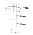
なお、このDVD再生装置1が再生する記録媒体100は、図14に示すように、映画の1作品等の単位とされて、Video Object Set(以下、VOBSという。)で記録されている。
【0037】
上記VOBSは、複数のVideo Object(以下、VOBという。)から構成されている。DVDは、例えば、1つの映画を複数のスト−リ−展開で見ることができるマルチスト−リ機能に対応して上記VOBごとで異なるスト−リ展開になるように構成されている。そして、VOBは、複数のCellにより構成される。
【0038】
上記Cellは、例えば映画における1シ−ン等の単位となる。すなわち、この1シ−ン毎の組み合わせがVOBとなり、この組み合わせの違いにより上記マルチスト−リ機能等を構成する。そして、Cellは、複数のVideo Object Unit(以下、VOBUという。)により構成されている。
【0039】
上記VOBUは、複数の主映像圧縮データ,副映像圧縮データ及び音声圧縮データのグループから構成される。主映像圧縮データ,副映像圧縮データ又は音声圧縮データは、後述するように、デマルチプレクサ5から主映像パック(V_PCK),副映像パック(SP_PCK)又は音声パック(A_PCK)にパック化されて出力される。
【0040】
上記主映像圧縮データは、映画の主映像となるデータであって、DVDフォーマットにおけるビデオストリームを構成する。また、副映像圧縮データは、字幕等のデータであって、DVDフォーマットにおけるサブピクチャーストリームを構成する。そして、音声圧縮データは、音声に関するデータであって、DVDフォーマットにおけるオーディオストリームを構成する。
【0041】
ここで、MPEG2方式でいうGOP(Group of Picture)は、DVDにおいて各アングルの映像データが細切れにされてなるアングルブロックとされ、インターリーブ構造を採用して、アングルブロックを混ぜてDVDに記録されている。GOPは、例えば1VOBU内にインターリーブ構造を採用して記録されている。そして、1GOPは、通常、図15に示すように、Iピクチャー,Pピクチャー及びBピクチャーによって構成され、これらIピクチャー,Pピクチャー及びBピクチャーが合計で15枚になるように構成されている。
【0042】
上記フォーマットによってデータが記録された記録媒体(DVD)100は、DVD再生装置1の備えるピックアップ2によってそのデータが読み出される。
【0043】
ピックアップ2は、当該ピックアップ2に組み込まれているレーザ光源からのレーザ光を記録媒体100の信号記録面に照射して、信号記録面で反射された反射光を受光する。ピックアップ2は、受光した光に応じて再生したRF信号をRF回路3に供給する。
【0044】
RF回路3は、このRF信号の波形等化及び2値化等をして再生データとその同期信号等を生成する。このRF回路3により生成されたディジタルデータ等は、データデコーダ4に供給される。
【0045】
データデコーダ4は、RF回路3により生成された再生データに基づきデータの復調や誤り訂正等の処理を行う。データデコーダ4により復調等がされたディジタルデータは、デマルチプレクサ5に供給される。
【0046】
ここで、ディジタルデータには、主映像圧縮データが含まれている。よって、符号化画像データは、ピックアップ2,RF回路3,データデコーダ4によって記録媒体100から読み出されたことになる。
【0047】
デマルチプレクサ5は、データデコーダ4によりエラー訂正のデコード処理等が施された記録媒体100から再生したディジタルデータを、各種パック、すなわち、主映像パック、副映像パック又は音声パックに分割して、後段の各デコーダに当該各パックを出力する。
【0048】
なお、デマルチプレクサ5と上記データデコーダ4の処理速度を吸収するために、デマルチプレクサ5とデータデコーダ4の間にトラックバッファが設けられている。
【0049】
デマルチプレクサ5は、主映像圧縮データからなる主映像パックをビデオデコーダ6に供給し、副映像圧縮パックからなる副映像パックを副映像デコーダ7に供給し、音声圧縮パックからなる音声パックをオーディオデコーダ8に供給する。
【0050】
ビデオデコーダ6は、供給された主映像パック内の主映像圧縮データの復号処理を行い、この復号処理により伸長化された主映像データを生成する。ここで、主映像データは、復号されたIピクチャー,Pピクチャー,Bピクチャーとされる復号画像データである。そして、ビデオデコーダ6は、復号処理を行うために上述のフレームメモリ14を有している。
【0051】
ここで、上記ビデオデコーダ6が上記フレームメモリ14を用いて行う復号処理について、例えばマルチアングル機能を実行可能に構成された例えばVOBU内の第9のマルチアングルの映像のIピクチャー又はIピクチャー及びPピクチャーを復号して、順方向再生を行う場合について説明する。なお、上記Iピクチャーの復号については、第1のVOBU、そして第2のVOBU内のIピクチャーI2を順次復号する場合について説明する。また、上記Iピクチャー及びPピクチャーの復号処理については、第1のVOBU内のIピクチャーI2,PピクチャーP5,PピクチャーP8を順次復号する場合について説明する。
【0052】
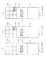
Iピクチャーのみの復号を行う場合、ビデオデコーダ6は、図3(a)に示すように、入力された主映像圧縮データを構成する内のIピクチャーI2を復号してフレームメモリ14の第1の復号用記憶領域14bに記憶する。ビデオデコーダ6は、IピクチャーI2の復号を、例えば第1の復号用記憶領域14b上で書き換えながら行う。
【0053】
復号後、ビデオデコーダ6は、図3(b)に示すように、復号したIピクチャーI2に縮小処理を施して、表示用記憶領域14aの第9のアングルの表示用の領域14a9に当該縮小処理を施した復号後のIピクチャーI2をコピーする。
【0054】
上記表示用記憶領域14aに縮小処理された記憶されたIピクチャーI2は、上記副映像デコーダ7及びNTSC変換回路9を介してモニタ200の分割された表示部に画像として映し出される。
【0055】
DVD再生装置1は、復号したIピクチャーI2による生成した画像を映す一方、図3(c)に示すように、フレームメモリ14の第1の復号用記憶領域14bに、次のIピクチャー、すなわ第2のVOBU内に記録されていたIピクチャーI2を記憶する。ここで、ビデオデコーダ6は、第1のVOBUのIピクチャーI2で行ったと同様に、この第2のVOBUのIピクチャーI2を復号して、その後に縮小処理を施し、表示用記憶領域14aにコピーする。
【0056】
上記表示用記憶領域14aに縮小処理されてコピーされた第2のVOBUのIピクチャーI2は、モニタ200において上記第1のVOBUのIピクチャーI2の次の画像とされて映し出される。詳しくは、上述のようにビデオデコーダ6において復号して得た復号画像データ(主映像データ)は、副映像デコーダ7に供給される。
【0057】
副映像デコーダ7は、供給された副映像パック内の副映像圧縮データの復号処理を行い、この復号処理をした副映像データをビデオデコーダ6から供給された上記主映像データに合成して、映像データを生成する。すなわち、副映像デコーダ7は、副映像データとして再生される字幕データ等を上記主映像データと合成する。なお、この副映像デコーダ7は、副映像データが無い場合には、主映像データをそのまま映像データとして出力する。副映像デコーダ7は、生成した映像データをNTSC変換回路9に供給する。
【0058】
NTSC変換回路9は、映像データをディジタルデータからNTSCやPAL等のテレビジョン信号に変換する。NTSC変換回路9からのテレビジョン信号は、モニタ200に映像として映し出される。
【0059】
モニタ200に入力されたテレビジョン信号には、上記ビデオデコーダ6で復号されたIピクチャーI2が含まれている。また、モニタ200は、上記フレームメモリ14の表示用記憶領域14aの分割された複数の記憶領域に対応して表示画面が9つに分割表示される。ここで、分割表示は、例えば表示用記憶領域の分割態様に従う。したがって、モニタ200の表示画面が分割されてなる一の表示部に、上記IピクチャーI2に基づく映像が映し出される。
【0060】
なお、オーディオデコーダ8は、音声パック内の音声圧縮データの復号処理を行い、伸長した音声データを生成する。すなわち、オーディオデコーダ8は、音声データがMPEG2方式によって圧縮されていれば、これに対応した伸長処理をして、音声圧縮データを生成する。また、オーディオデコーダ8は、MPEG2のフォーマットの他に、リニアPCM又はドルビーAC3のフォーマットであれば、これに対応した処理を行う。オーディオデコーダ8は、生成した音声データをA/D変換回路10に供給する。
【0061】
A/D変換回路10は、ディジタルデータである音声データをアナログの音声データに変換して出力する。この出力をスピーカ等に供給することにより、ユーザーが記録媒体100から再生した映像を視聴することができる。
【0062】
コントローラ11は、ピックアップ2,RF回路3,データデコーダ4,デマルチプレクサ5,ビデオデコーダ6,副映像デコーダ7,オーディオデコーダ8,NTSC変換回路9及びA/D変換回路10の制御を行う。また、このコントローラ11には、操作パネルやリモートコントローラであるユーザーインターフェース12を介して操作入力がされ、この操作入力に基づき各回路の制御を行う。
【0063】
このコントローラ11は、ビデオデコーダ6を介して、フレームメモリ14での書き込み制御及び読み出し制御を行う。すなわち、コントローラ11は、フレームメモリ14の復号用記憶領域に記憶されている復号画像データの縮小処理及び当該縮小処理した一の復号画像データを表示用記憶領域14aの分割表示のために形成される一の記憶領域に書き込み制御を行う。そして、コントローラ11は、表示用記憶領域14a内に記憶された復号画像データの読み出す読み出し制御を行う。
【0064】
なお、復号画像データの表示記憶領域14aからの読み出しは、表示記憶領域14a単位の表示画像データの読み出しによって行われる。表示画像データによって、上記記憶領域に200対応して上記一の記憶画像に記憶されている復号画像データによる画像がモニタの当該記憶領域に対応する表示位置に映し出される。
【0065】
よって、上述の第9のアングルのIピクチャーに対して行った復号及び縮小処理を第1乃至第8のアングルのIピクチャーに対しても同様に行うことで、DVD再生装置1は、第9のアングルの映像と同時刻における第1乃至第8のアングルの映像を同時にモニタ200に映し出すことができる。この場合、例えば、各アングルの画像を構成する符号化画像データの復号は、図5(a)乃至図5(d)に示すように、第1のアングルの画像(200a),第2のアングルの画像(200b),・・・・・,第9のアングルの画像(200i),そして第1のアングルの画像(200a)を生成するような手順で行う。
【0066】
なお、Iピクチャーを復号するだけであれば、フレームメモリ14は、上述のように少なくとも1つの復号用記憶領域を備えていればよい。
【0067】
また、Iピクチャー及びPピクチャーの復号の場合については、ビデオデコーダ6は、図4(a)に示すように、入力されたIピクチャーI2が先ず復号してフレームメモリ14の第1の復号用記憶領域14bに記憶される。
【0068】
復号後、ビデオデコーダ6は、図4(b)に示すように、復号したIピクチャーI2に縮小処理を施して、表示用記憶領域14aの第9のアングルの表示用の領域14a9に当該縮小処理を施した復号後のIピクチャーI2をコピーする。
【0069】
上記表示用記憶領域14aに縮小処理されて記憶されたIピクチャーI2によって生成された画像は、フレームメモリ14の表示用記憶領域14aに対応したモニタ200の一の表示部に映し出される。
【0070】
一方、ビデオデコーダ6は、図4(c)に示すように、次に入力されたPピクチャーP5を、第1の復号用記憶領域14bに記憶されている復号後のIピクチャーI2によって予測して復号し、第2の復号用記憶領域14cに記憶する。
【0071】
第2の復号用記憶領域14cに復号後のPピクチャーP5を記憶した後、ビデオデコーダ6は、図4(d)に示すように、復号したPピクチャーP5に縮小処理を施して、表示用記憶領域14aの領域14a9に当該縮小処理を施した復号後のPピクチャーP5をコピーする。
【0072】
上記表示用記憶領域14aに縮小処理されて記憶されたPピクチャーP5によって生成された画像は、モニタ200の上記一の表示部に映し出されていた上記IピクチャーI2の次の画像として映し出される。
【0073】
PピクチャーP8を復号する際には、ビデオデコーダ6は、図4(e)に示すように、次に入力されたPピクチャーP8を、第2の復号用記憶領域14cに記憶されている復号後のPピクチャーP5によって予測して復号し、第1の復号用記憶領域14bに記憶する。
【0074】
第1の復号用記憶領域14bに復号後のPピクチャーP8を記憶した後、ビデオデコーダ6は、図4(f)に示すように、復号したPピクチャーP8に縮小処理を施して、表示用記憶領域14aの領域14a9に当該縮小処理を施した復号後のPピクチャーP8をコピーする。
【0075】
上記表示用記憶領域14aに縮小処理されて記憶されたPピクチャーP8によって生成された画像は、モニタ200の上記一の表示部に映し出されていた上記PピクチャーP5の次の画像として映し出される。
【0076】
よって、モニタ200の上記一の表示部には、復号されたIピクチャー,Pピクチャーに基づく画像が次々に映し出されたことになる。
【0077】
DVD再生装置1は、第9のアングルのIピクチャー及びPピクチャーに対して行った上述の復号及び縮小処理を第1乃至第8のアングルのIピクチャー及びPピクチャーに対しても同様に行うことで、第9のアングルの映像と同時刻における第1乃至第8のアングルの映像をモニタ200の対応した各表示部に映し出すことができる。
【0078】
上述のIピクチャー又はIピクチャー及びPピクチャーのみの復号によって行う順方向再生は、例えば高速再生を実行する場合に適用される。また、通常の再生を行うのであれば、フレームメモリ14にさらに復号用記憶領域を設ければよい。
【0079】
また、DVD再生装置1は、逆方向再生を行うこともでき、上述のように同時刻の第1乃至第9のアングルの映像をモニタ200に映し出すこともできる。例えば、Iピクチャーを用いた逆方向再生は、第nのVOBU内のIピクチャーを復号した後、第n−1のVOBU内のIピクチャーを復号するというように、GOP内のIピクチャーを復号して行う。
【0080】
そして、Iピクチャー及びPピクチャーを用いた逆方向再生は、先ず第1の復号用記憶領域14bでIピクチャーを復号して、それをもとに第2の復号用記憶領域でPピクチャーを復号を行う。例えば、第1の復号用記憶領域14cでIピクチャーI2を復号し、その復号したIピクチャーI2をもとに同一のVOBU内のPピクチャーP5を第2の復号用記憶領域14cで復号するというように復号処理を行い、モニタ200への表示を復号順とは逆にする、すなわちPピクチャーP5,IピクチャーI2の順序で再生することで逆方向再生を行う。
【0081】
次にDVD再生装置1が逆方向再生可能に構成したフレームメモリ14について、例えば、第9のアングルの映像を構成するIピクチャー及びPピクチャーを復号する場合について説明する。
【0082】
逆方向再生可能に構成したフレームメモリ14は、図6に示すように、9つの記憶領域を形成する表示用記憶領域14aと、Iピクチャー又はPピクチャーの復号後の復号画像データを記憶する第1の復号記憶領域14b,第2の復号記憶領域14c及び第3の復号用記憶領域14dとを有して構成される。
【0083】
すなわち、逆方向再生に適用する場合は、フレームメモリ14にさらに第3の復号用記憶領域14dを設ける。
【0084】
逆方向再生する場合、図7(a)に示すように、入力されたIピクチャーI2を復号してフレームメモリ14の第1の復号用記憶領域14bに記憶する。
【0085】
その後、ビデオデコーダ6は、図7(b)に示すように、次に入力したPピクチャーP5を、第1の復号用記憶領域14bに記憶されている復号後のIピクチャーI2を用いた予測により復号して、第2の復号用記憶領域14cに記憶する。
【0086】
さらにその後、ビデオデコーダ6は、図7(c)に示すように、次に入力したPピクチャーP8を、第2の復号用記憶領域14cに記憶されている復号後のPピクチャーP5を用いた予測により復号して、第3の復号用記憶領域14dに記憶する。
【0087】
そして、表示用記憶領域14aへの各復号データのコピーは、上記復号の処理を行ったのと逆の順番で行う。すなわち、図7(d)に示すように、先ず第3の復号用記憶領域14dに記憶されている復号後のPピクチャーP8に縮小処理を施して、表示用記憶領域14aの第9のアングルの表示用の領域14a9に当該縮小処理を施した復号後のPピクチャーP8をコピーする。
【0088】
次に、図7(e)に示すように、第2の復号用記憶領域14cに記憶されている復号後のPピクチャーP5に縮小処理を施して、表示用記憶領域14aの領域14a9に当該縮小処理を施した復号後のPピクチャーP5をコピーする。
【0089】
そして、図7(f)に示すように、第1の復号用記憶領域14bに記憶されている復号後のIピクチャーI2に縮小処理を施して、表示用記憶領域14aの領域14a9に当該縮小処理を施した復号後のIピクチャーI2をコピーする。
【0090】
上述のように、PピクチャーP8,PピクチャーP5,IピクチャーI2を表示用記憶領域14aの領域14a9に順次コピーすることによって、DVD再生装置1は、上記領域14a9に対応するモニタ200の一の表示部に、PピクチャーP8,PピクチャーP5,IピクチャーI2の画像を順次表示することができる。
【0091】
なお、上述のIピクチャー及びPピクチャーのみの復号によって行う逆方向再生は、例えば高速逆再生を実行する場合に適用される。また、通常の逆方向再生を行うのであれば、フレームメモリ14に復号用記憶領域を1つ設ければよい。
【0092】
以上、Iピクチャー又はIピクチャー及びPピクチャーのみの復号によって行うように構成されたフレームメモリ14及びこのフレームメモリ14を用いて逆方向再生を行う場合の説明である。
【0093】
DVD再生装置1は、上述のように構成したフレームメモリ14を備えることで、順方向再生及び逆方向再生において、同時刻における複数のアングルの映像を同時に表示することが可能になる。
【0094】
これにより、例えば、シームレスな映像切り換えにおいて問題とされた切り換えた瞬時の他のアングルの映像を見逃すという問題を解消することもできる。例えば、視聴者は、シームレスな映像を見ることができ、且つ見たい他のアングルの映像も同時に見ることができる。
【0095】
なお、再生するアングルの映像は、シームレスな映像ばかりでなく、ノンシームレスな映像であってよい。
【0096】
また、各アングルの映像は、例えば1VOBU単位として構成され、さらに、同時刻の映像の各アングルの映像は各VOBU間で属性をもっている。すなわち、DVD再生装置1は、各アングルの映像の再生においては、上記対応づけされた各VOBU内のピクチャーを復号している。
【0097】
しかし、これに限定されず、DVD再生装置1は、例えば、順方向再生時であって、他のアングルの映像のピクチャーを復号する場合、次の時刻に属するVOBUの上記他のアングルの映像を構成するピクチャーを復号していくこともできる。また、DVD再生装置1は、逆方向再生時であって、他のアングルの映像のピクチャーを復号する場合、真の時刻に属するVOBUの上記他のアングルの画像を構成するピクチャーを復号していくこともできる。
【0098】
次に第2の実施の形態について説明する。第2の実施の形態は、本発明に係る信号再生装置及び方法を適用し、DVDを再生するように構成したDVD再生装置である。
【0099】
なお、DVDは、上述の第1の実施の形態と同様にマルチアングル機能を有するようなデータフォーマットで構成されている。すなわち、DVDは、MPEG2方式を採用しており、映像を、Iピクチャー,Pピクチャー及びBピクチャーとして圧縮符号化して記録している。以下、異なる2つのアングルの映像が記録されているDVDを再生する場合について説明する。
【0100】
DVD再生装置は、図8に示すように、2個のビデオデコーダを備えて、この2個のビデオデコーダによって復号して得た復号画像データの出力を切り換えて後段の回路に出力している。
【0101】
詳しくは、DVD再生装置1は、記録媒体100からRF信号を再生するピックアップ2と、このピックアップ2により再生されたRF信号がされ、このRF信号を2値化処理を行うRF回路3と、RF回路3からの再生データ等が供給され、エラー訂正等のデコード処理をするデータデコーダ4と、第1の記憶領域21a及び第2の記憶領域21bを有し、データデコーダ4から出力されたディジタルデータを記憶するトラックバッファ21と、データデコーダ4によりデコード処理がされたディジタルデータを主映像圧縮データ,副映像圧縮データ,音声圧縮データに振り分けるデマルチプレクサ5とを備える。
【0102】
また、DVD再生装置1は、デマルチプレクサ5から出力された上記主映像圧縮データを復号する第1のビデオデコーダ22及び第2のビデオデコーダ23と、上記副映像圧縮データを復号して主映像データと合成する副映像デコーダ7と、上記音声圧縮データを復号するオーディオデコーダ8と、副映像デコーダ7からの副映像データと主映像データが合成された映像データが供給されNTSC信号又はPAL信号に変換するデジタル/NTSC,PAL変換回路(以下、単にNTSC変換回路という。)9と、オーディオデコーダ8からのオーディオデータが供給されアナログ信号に変換するデジタル/アナログ変換回路(以下、単にA/D変換回路という。)10とを備える。
【0103】
さらに、DVD再生装置1は、ピックアップ2,RF回路3,データデコーダ4,デマルチプレクサ5,第1のビデオデコーダ22,第2のビデオデコーダ23,切り換えスイッチ24,副映像デコーダ7,オーディオデコーダ8,NTSC変換回路9及びA/D変換回路10を制御するコントローラ11と、このコントローラ11とユーザーの操作入力を媒介するユーザーインターフェース12と、コントローラ11のデータ記憶部となるメモリ13とを備える。
【0104】
上記記録媒体100からRF信号を再生するピックアップ2、このRF信号を信号処理するRF回路3及びRF回路3で信号処理された再生データを復号するデータデコーダ4は、それぞれが処理速度を、通常処理の例えば2倍にすることができるように構成している。ここで、通常処理は、記録媒体100から、例えば1つのアングルの映像分を読み込んで行った場合の処理をいう。
【0105】
また、上記デマルチプレクサ5も、データの処理速度を、通常処理の2倍にすることができるように構成している。これにより、デマルチプレクサ5は、入力されてくる主映像圧縮データ,副映像圧縮データ及び音声圧縮データの振り分けを上記通常処理と異なることなく行うことができる。
【0106】
以下、上記DVD再生装置1の構成部分について説明する。なお、第1の実施の形態となるDVD再生装置1で説明した部分については、図2と同一の番号を付し、その説明を省略する。
【0107】
DVD再生装置1は、記録媒体100に記録されている符号化画像データ等をピックアップ2、RF回路3及びデータデコーダ4を介してトラックバッファ21に入力する。
【0108】
上記トラックバッファ21は、第1の記憶領域21a及び第2の記憶領域21bの2つの記憶領域を有している。トラックバッファ21は、上記各記憶領域に入力されたディジタルデータを記憶する。ここで、ディジタルデータは、上述したように、デマルチプレクサ5によって分割される主映像圧縮データ,副映像圧縮データ,音声圧縮データを含んでいる。
【0109】
このトラックバッファ21は、上記データデコーダ4とデマルチプレクサ5との処理速度の違いを吸収している。そして、トラックバッファ4は、デマルチプレクサ5からの転送命令によってディジタルデータを当該デマルチプレクサ5に出力する。
【0110】
デマルチプレクサ5は、上述したように通常処理速度の2倍の処理速度を有している。デマルチプレクサ5は、トラックバッファ21の上記各記憶領域から出力されたディジタルデータを交互に取り込み、取り込んだディジタルデータを主映像圧縮データ,副映像圧縮データ及び音声圧縮データに分割して、第1のビデオデコーダ22又は第2のビデオデコーダ23、副映像デコーダ7及び音声デコーダ8に出力する。
【0111】
第1のビデオデコーダ22及び第2のビデオデコーダ23に出力される主映像圧縮データは、いわゆる符号化画像データであって、いわゆるIピクチャー,Pピクチャー,Bピクチャーによって構成されるデータである。そして、出力は、例えば1GOP単位となるように上記各ビデオデコーダ6に対して行われる。また、上記主映像圧縮データ,副映像圧縮データ及び音声圧縮データは、パック化されてデマルチプレクサ5の後段に備えた各デコーダに供給される。
【0112】
なお、第1のビデオデコーダ22及び第2のビデオデコーダ23とは、それぞれがIピクチャー,Pピクチャー,Bピクチャーの復号のために3つの復号用記憶領域を備えたフレームメモリを有している。
【0113】
第1のビデオデコーダ22及び第2のビデオデコーダ23は、入力された各符号化画像データを復号する。ここで行う復号処理は、フレーム間予測によって行う。この第1のビデオデコーダ22及び第2のビデオデコーダ23によって復号された復号画像データは、切り換えスイッチ24に入力される。
【0114】
切り換えスイッチ24は、上記第1のビデオデコーダ22又は第2のビデオデコーダ23からの復号画像データの何れか一方を後段の副映像デコーダ7に供給する。切り換えスイッチ24のスイッチングは、コントローラ11によって行われる。
【0115】
例えば、第1のビデオデコーダ21からの復号画像データの出力中に切り換えの命令を受けた場合、切り換えスイッチ24は、切り換え動作によって、出力するデータを第2のビデオデコーダ23からの復号画像データに切り換える。よって、上記第1のビデオデコーダ22及び第2のビデオデコーダ23で復号された符号化画像データは、この切り換えスイッチ24によって、何れか一方が出力されるように瞬時に切り換えられる。例えばこの様なスイッチングは、アングルの映像の切り換えの際に行われる。
【0116】
上記切り換えスイッチ24を介して出力された復号画像データは、副映像デコーダ7及びNTSC変換回路9を介してモニタ200に画像として表示される。
【0117】
よって、第2の実施の形態となるDVD再生装置1は、一のアングルの映像の再生中に他のアングルの映像に瞬時に切り換えて再生することができるため、当該切り換えた瞬間の他のアングルの映像をモニタ200に表示することができる。
【0118】
このDVD再生装置1によって、例えば、視聴者は、他のアングルの映像に切り換えた時に見たい当該他のアングルの映像を見逃すことがなくなる。
【0119】
ここでいうアングルの映像は、シームレスな映像ばかりでなく、ノンシームレスな映像であってもよく、DVD再生装置1は、これらの映像の種類に関係なく瞬時に切り換えて再生することができる。
【0120】
なお、上記他のアングルの映像に切り換えても副映像データ及び音声データについては、例えば、上記一のアングルの映像のデータのものを用いる。つまり、上記他のアングルの映像の副映像データ及び音声データは、上記デマルチプレクサ5から出力されることもなく、また、復号されることもない。
【0121】
また、第1のビデオデコーダ22に入力される符号化画像データと第2のビデオデコーダ23に入力される符号化画像データとでビットレートに違いがある場合、デマルチプレクサ5と第1のビデオデコーダ22の間に設けられている図示しないビデオバッファの空き領域とデマルチプレクサ5と第2のビデオデコーダ23との間に設けられている図示しないビデオバッファの空きの容量とを、例えばコントローラ11によって監視して、空きの領域のあるビデオバッファにデマルチプレクサ5からデータを送出すればよい。なお、各ビデオバッファは、デマルチプレクサ5の分配処理の処理速度と各ビデオデコーダ復号の処理速度の違いを吸収するバッファである。すなわち、このバッファを用い、一のバッファに空きがなくなったら、他のバッファにデータを送出して、ビットレートの違いを吸収する。
【0122】
また、第2の実施の形態となるDVD再生装置1に、図9に示すように、通常の処理速度の2倍の処理速度をもつビデオデコーダ26と、デマルチプレクサ5とビデオデコーダ26との間に設けた切り換えスイッチ25とを備えることもできる。
【0123】
上記切り換えスイッチ25は、デマルチプレクサ5からの符号化画像データを、例えば1GOP単位でビデオデコーダ26に出力する。この切り換えスイッチ25のスイッチングは、コントローラ11によって行われる。
【0124】
例えば、一のアングルの映像に対応する符号化画像データの出力中に切り換えの命令が出された場合、切り換えスイッチ25は、他のアングルの映像に対応する符号化画像データを出力する。よって、この切り換えスイッチ25の切り換え動作によって、一のアングルの映像に対応する符号化画像データ又は他のアングルの映像に対応する符号化画像データの何れか一方が出力される。
【0125】
上記ビデオデコーダ26は、切り換えスイッチ25からの符号化画像データを通常の2倍の処理速度で復号処理を行うことができる。そして、ビデオデコーダ26で復号して得た復号圧縮データは、副映像デコーダ7及び副映像デコーダ7及びNTSC変換回路9を介してモニタ200に画像として表示される。
【0126】
よって、上記切り換えスイッチ25及び2倍の復号処理をもつビデオデコーダ26を備えることでも、DVD再生装置1は、シームレスな映像で且つ瞬時に映像のアングルを切り換えることができる。
【0127】
次に第3の実施の形態について説明する。この第3の実施の形態は、本発明に係る信号再生装置及び方法を適用し、DVDを再生するように構成したDVD再生装置である。
【0128】
この第3の実施の形態となるDVD再生装置は、複数のアングルの映像を同時に再生するように構成している。そのため、このDVD再生装置は、図10に示すように、デマルチプレクサ5からの主映像圧縮データがそれぞれ入力される第1のビデオデコーダ23及び第2のビデオデコーダ24と、この第1のビデオデコーダ22及び第2のビデオデコーダ23からそれぞれ出力された復号画像データを混合する混合回路27とを有している。
【0129】
すなわち、第3の実施の形態となるDVD再生装置1は、第2の実施の形態として用いたDVD再生装置1における切り換えスイッチ24に代えて混合回路27を備える構成を採る。
【0130】
このように構成されたDVD再生装置1は、混合回路27によって、第1のビデオデコーダ22から出力された復号画像データと第2のビデオデコーダ23から出力された復号画像データとを混合してモニタ200に供給することができるようになる。
【0131】
例えば、第1のビデオデコーダ22から第1のアングルの映像を構成する復号画像データが出力され、第2のビデオデコーダ23から第1のアングルの映像を構成する復号画像データが出力された場合、図12(a)乃至図12(b)に示すように、第1のアングルの画像(図12(a)に示す。)と第2のアングルの画像(図12(b)に示す。)とを同時に表示(図12(c)に示す。)することができる。
【0132】
なお、図12(c)に示すように、モニタ200の画面内において第1のアングルの画像と第2のアングルの画像とが重ならないようにするのであれば、DVD再生装置1は、第1のビデオデコーダ23と第2のビデオデコーダ24とで3つの復号用記憶領域からなるフレームメモリを共有することができる。
【0133】
また、フレームメモリを第1のビデオデコーダ22及び第2のビデオデコーダ23の各々が備えることによって、図13(a)乃至図13(b)に示すように、第1のアングルの画像(図13(a)に示す。)をモニタ200の表示画面全体を使い、また第2のアングルの画像(図13(b)に示す。)をモニタ200の表示画面の一部を使い表示(図13(c)に示す。)することもできる。
【0134】
また、DVD再生装置1は、3つの復号用記憶領域からなるフレームメモリを用いることで、Iピクチャー,Pピクチャー及びBピクチャーを復号することができ、通常の再生が可能になる。
【0135】
よって、DVD再生装置1は、上述のように2つのビデオデコーダを備えたときと同様に、同時に2つ異なるアングルの映像を通常再生することができ、当該通常再生した2つのを異なるアングルの映像をモニタ200に表示することができる。
【0136】
次に第4の実施の形態について説明する。この第4の実施の形態は、本発明に係る信号再生装置及び方法を適用し、DVDを再生するように構成したDVD再生装置である。
【0137】
この第4の実施の形態となるDVD再生装置は、複数のアングルの映像を同時に再生することができ、またシームレス且つ瞬間的に再生中のアングルの映像を切り換えることができるように構成している。そのため、このDVD再生装置は、図11に示すように、デマルチプレクサ5からの主映像圧縮データがそれぞれ入力される第1のビデオデコーダ22及び第2のビデオデコーダ23と、この第1のビデオデコーダ22及び第2のビデオデコーダ23からそれぞれ出力された復号画像データを混合する混合回路27と、第1のビデオデコーダ22から出力される復号画像データについて混合回路27に対して送出をオン及びオフするスイッチ28と、第2のビデオデコーダ23から出力される復号画像データについて混合回路27に対しての送出をオン及びオフするスイッチ29とを有している。
【0138】
このように構成したDVD再生装置1は、スイッチ28及びスイッチ29をオンにした状態では、混合回路27によって、第1のビデオデコーダ22から出力された復号画像データと第2のビデオデコーダ23から出力された復号画像データとを混合してモニタ200に供給することができる。例えば、混合された映像が、図12(c)及び図13(c)に表示されるように、DVD再生装置1は、モニタ200に供給することができる。
【0139】
さらに、DVD再生装置1は、スイッチ28及びスイッチ29のオン/オフの操作によって、第1のビデオデコーダ22及び第2のビデオデコーダ23を切り換えて符号化画像データの復号を行うこともできる。この場合、スイッチ28がオンのときスイッチ29をオフにして、またスイッチ28がオフのときスイッチ29をオンにする。
【0140】
例えば、第1のビデオデコーダ22からの一のアングルの映像を構成する復号画像データの出力中に切り換えの命令が出された場合、スイッチ28をオフにして、一方でスイッチ29をオンにすることで、第2のビデオデコーダ23から他のアングルの映像を構成する復号画像データを出力することができるようになる。すなわち、上記第1のビデオデコーダ22及び第2のビデオデコーダ23で復号された画像圧符号化データの何れか一方が瞬時に切り換えられて出力される。
【0141】
よって、DVD再生装置1は、一のアングルの映像の再生中に他のアングルの映像に瞬時に切り換えて再生することができ、当該切り換えた他のアングルの映像をモニタ200に表示することができる。
【0142】
以上のことから第4の実施の形態となるDVD再生装置1は、複数のアングルを同時に再生すること、またシームレスな映像であっても瞬時に他のアングルの映像に切り換えることもできる。
【0143】
このDVD再生装置1によって、例えば、視聴者は、他のアングルの映像を同時に見ることができ、さらに切り換え操作によって他のアングルの見たいときでも、切り換えたときに見たいアングルの映像を見逃すことがなくなる。
【0144】
なお第2乃至第4の実施の形態となるDVD再生装置1を、2つのアングルの映像が記録されたDVDの再生を例に挙げて説明したが、3つ以上、例えば複数mのアングルの映像が記録されているDVDを再生することもできる。この場合、DVD再生装置1は、2個及び2倍の処理速度をそれぞれm個及びm倍の処理速度になるように各部を構成する。
【0145】
【発明の効果】
本発明に係る信号再生装置は、読み出し手段で読み出した複数アングルの内の一のアングルの符号化画像データを復号して複数アングルの復号画像データを生成する復号手段と、復号手段によって生成した複数アングルの内の一のアングルの復号画像データを記憶する復号用記憶手段と、表示画像データを記憶し、分割表示するための記憶領域が形成される表示用記憶手段と、復号用記憶手段に記憶されている復号画像データに縮小処理を施して、この縮小処理した復号画像データを表示用記憶手段の記憶領域に書き込み、この記憶領域に書き込まれた復号画像データを含む表示画像データを読み出す制御手段とを備えることで、符号化画像データによって構成される複数のアングルの映像を同時に再生することができる。
【0146】
よって、上記信号再生装置は、例えば、ノンシームレスであるか否かに関わらず映像を同時に提供することができ、視聴者は、見たい映像を見逃すこともなくなる。
【0147】
また、本発明に係る信号再生装置は、読み出し手段で読み出した符号化画像データを記憶するm個の記憶手段と、m個の記憶手段から出力された上記符号化画像データを復号して復号画像データを生成する復号手段とを備えることで、複数の符号化画像データを復号して、瞬時に切り換えて又は同時に、複数のアングルの映像を再生することができる。
【0148】
そして、上記信号再生装置は、例えば、シームレスな映像の再生においても、瞬時に他のアングルの映像に切り換えることができる。
【0149】
さらに、本発明に係る信号再生方法は、上述の課題を解決するために、読み出し工程で読み出した複数アングルの内の一のアングルの符号化画像データを復号して複数アングルの復号画像データを生成する復号工程と、復号工程によって生成した複数アングルの内の一のアングルの復号画像データを記憶する復号画像データ記憶工程と、分割表示するための記憶領域が形成されて、表示画像データを記憶する表示用記憶工程と、復号画像データ記憶工程で記憶されている上記復号画像データに縮小処理を施して、この縮小処理した復号画像データを上記表示用記憶工程の有する上記記憶領域に書き込み、この上記記憶領域に書き込まれた上記復号画像データを含む表示画像データを読み出す制御工程とを有することで、符号化画像データによって構成される複数のアングルの映像を同時に再生することができる。
【0150】
よって、上記信号再生方法によれば、例えば、ノンシームレスであるか否かに関わらず映像を同時に提供することができ、視聴者は、見たい映像を見逃すこともなくなる。
【0151】
また、本発明に係る信号再生方法は、上述の課題を解決するために、読み出し工程で読み出した符号化画像データを記憶するm段の記憶工程と、m段の記憶工程から出力された符号化画像データを復号して復号画像データを生成する復号工程とを有することで、複数の符号化画像データを復号して、瞬時に切り換えて又は同時に、複数のアングルの映像を再生することができる。
【0152】
そして、上記信号再生方法によれば、例えば、シームレスな映像の再生においても、瞬時に他のアングルの映像に切り換えることができる。
【図面の簡単な説明】
【図1】本発明の第1の実施の形態となるDVD再生装置の備えるフレームメモリを示す構成図である。
【図2】上記DVD再生装置を示す回路図である。
【図3】上記フレームメモリにおいて、符号化画像データを復号するとき、特にIピクチャーを復号する様子を示す構成図である。
【図4】上記フレームメモリにおいて、符号化画像データを復号するとき、特にIピクチャー及びPピクチャーを復号する様子を示す構成図である。
【図5】符号化画像データを復号する手順の説明に用いたモニタを示す平面図である。
【図6】逆再生用に構成した上記フレームメモリを示す構成図である。
【図7】上記逆再生用に構成したフレームメモリにおいて、符号化画像データを復号するとき、特にIピクチャー及びBピクチャーを復号する様子を示す構成図である。
【図8】本発明の第2の実施の形態となるDVD再生装置を示す回路図である。
【図9】上記第2の実施の形態となるDVD再生装置の要部を変更した場合を示す回路図である。
【図10】本発明の第3の実施の形態となるDVD再生装置の要部構成を示す回路図である。
【図11】本発明の第4の実施の形態となるDVD再生装置の要部構成を示す回路図である。
【図12】複数のアングルの画像が表示されているモニタを示す平面図である。
【図13】複数のアングルの画像が他の表示の仕方で表示されているモニタを示す平面図である。
【図14】上記第1乃至第4の実施の形態となるDVD再生装置によって再生されるDVDを示すデータフォーマットである。
【図15】上記DVDに記録されているGOPを示すデータフォーマットである。
【符号の説明】
1 信号再生装置、2 ピックアップ、3 RF回路、4 データデコーダ、5 デマルチプレクサ、14 フレームメモリ、14a 表示用記憶領域、14b 第1の復号用記憶領域、14c 第2の復号用記憶領域、14d 第3の復号用記憶領域、21 トラックバッファ、22 第1のビデオデコーダ、23 第2のビデオデコーダ、24 切り換えスイッチ、25 切り換えスイッチ、26 ビデオデコーダ、27 混合回路、28 スイッチ、29 スイッチ[0001]
BACKGROUND OF THE INVENTION
The present invention relates to a signal reproducing apparatus and method for reproducing encoded moving picture data by decoding encoded image data, and more particularly to a signal reproducing apparatus and method for reproducing a plurality of moving pictures having the same attribute.
[0002]
[Prior art]
A characteristic common to optical disks is random access. A DVD (digital video disc: DVD-VIDEO), which is an optical disc, incorporates a multi-angle function, a multi-story function, and the like, taking advantage of this feature.
[0003]
The multi-angle function is a function for playing back images taken simultaneously from a plurality of different camera angles, for example, a function that makes it possible to play back images of a plurality of angles with respect to one image.
[0004]
In the DVD, data that enables selective reproduction of the plurality of angles is configured as an angle block. The angle block is formed by cutting the video data of each angle into small pieces. In the DVD, a so-called interleave structure is adopted, and the angle blocks are mixed and recorded on the signal recording surface. The DVD adopts such a data recording structure, thereby realizing the multi-angle function and the multi-story function.
[0005]
For example, the DVD playback device can play back a DVD as described above, and switch to a video of the desired angle during playback in real time.
[0006]
Note that there are two types of the angle block, and an angle block (hereinafter referred to as SML_AG_BLK) that can be seamlessly connected to other angles when a simultaneous image is switched, that is, seamlessly. There are other angle blocks, that is, angle blocks (hereinafter referred to as NSML_AGL_BLK) whose angles can be switched only in a non-seamless manner.
[0007]
[Problems to be solved by the invention]
By the way, when the SML_AG_BLK is played, the DVD playback device can seamlessly switch the angle, but it takes about several seconds to switch the angle after switching the angle. That is, the DVD playback apparatus cannot play back another angle at the moment of switching the angle. Therefore, even if the viewer switches when he / she wants to view a video at another angle, he / she cannot see the video at the other angle at the moment of switching, and misses the desired video.
[0008]
Further, in the reproduction of the SML_AG_BLK, the angle switching is limited to once every several seconds. In all angles, the sub-picture data including the audio data and the caption information is encoded only for those related to the video of the angle to be reproduced.
[0009]
[Means for Solving the Problems]
In order to solve the above-described problem, the signal reproduction device according to the present invention reads the encoded image data of the multi-angle video from the recording medium on which the multi-angle video is recorded as the encoded image data. A reading unit; a decoding unit configured to decode the encoded image data of one angle among the plurality of angles read by the reading unit to generate the decoded image data of the plurality of angles; and the above-described generated by the decoding unit. Decoding storage means for storing the decoded image data of one angle among a plurality of angles, a display for storing display image data, and forming a divided storage area for dividing and displaying the image data of the plurality of angles Storage unit and the decoded image data stored in the decoding storage unit are subjected to a reduction process, and the reduced image Control means for writing the decoded image data of the guru into the divided storage area of the display storage means and reading out the display image data including the decoded image data of the one angle written in the divided storage area, The encoded image data read from the recording medium includes intra-frame encoded image data and inter-frame forward encoded image data, and the decoding storage unit includes at least two decoding storage areas, and the code By decoding the intra-frame encoded image data and the inter-frame forward encoded image data of the encoded image data and storing them in the at least two decoding storage areas, the images of the plurality of angles can be reproduced during the forward and reverse reproduction. It is characterized by being played back simultaneously.
[0010]
In the reproduction of NSML_AG_BLK, another angle at the moment of switching the angle can be reproduced. Further, there are generally more places where the angle can be switched than the SML_AG_BLK. Further, even when switching to a video of another angle, audio data and sub-video data different from the video of the other angle can be decoded.
[0011]
When the NSML_AG_BLK and NSML_AG_BLK are played, the DVD playback device cannot switch the angle smoothly and instantaneously even if the angle can be switched.
[0012]
In addition, for example, if the video display of each angle can be provided to the viewer at the same time, each angle video can be confirmed at all times, so that the video can be overlooked by switching each angle and the difficulty of viewing can be eliminated as described above. Therefore, it is also desirable to provide an apparatus that can simultaneously display a plurality of angles of video.
[0013]
Therefore, the present invention has been made in view of the above-described circumstances, and can smoothly and smoothly view images of a plurality of angles recorded on a recording medium at the same time or even when switched. An object of the present invention is to provide a signal reproducing apparatus and method.
[0014]
[Means for Solving the Problems]
In order to solve the above-described problem, the signal reproduction device according to the present invention decodes encoded image data of one angle among a plurality of angles read by the reading unit to generate decoded image data of a plurality of angles. Means, decoding storage means for storing decoded image data of one angle among a plurality of angles generated by the decoding means, and display memory for storing display image data and forming a storage area for division display And the decoded image data stored in the decoding storage means, the reduced image data is written in the storage area of the display storage means, and the decoded image data written in the storage area is written. Control means for reading display image data including By providing these, the signal reproduction device stores a plurality of decoded image data in each storage area of the display storage means.
[0016]
In addition, in order to solve the above-described problem, the signal reproduction method according to the present invention encodes the multi-angle video encoded image data from the recording medium on which the multi-angle video is recorded as the encoded image data. A decoding step of decoding the encoded image data of one angle among the plurality of angles read out in the reading step, and generating the decoded image data of the plurality of angles, and generating by the decoding step A decoded image data storage step for storing the decoded image data of one angle among the plurality of angles in the storage unit for decoding, and a divided storage area for dividing and displaying the image data of the plurality of angles are formed. A display storage step for storing display image data in the display storage means, and the decoded image data stored in the decoding storage means. The decoded image data of the one angle subjected to the reduction processing is written in the divided storage area of the display storage unit, and the decoded image data of the one angle written in the divided storage area is written. The encoded image data read from the recording medium includes intra-frame encoded image data and inter-frame forward encoded image data, and The storage means includes at least two decoding storage areas, and decodes the intra-frame encoded image data and the inter-frame forward encoded image data of the encoded image data and stores them in the at least two decoding storage areas. Thus, the above-mentioned multi-angle videos are simultaneously reproduced during forward and backward reproduction.
[0018]
DETAILED DESCRIPTION OF THE INVENTION
Hereinafter, embodiments of the present invention will be described with reference to the drawings.
[0019]
First, a first embodiment is a DVD reproducing apparatus configured to reproduce a DVD (digital video disk: DVD-VIDEO) by applying the signal reproducing apparatus and method according to the present invention.
[0020]
Note that a DVD is a recording medium on which an image compression-encoded by MPEG2 (Moving Picture Coding Experts Group 2) is recorded. As data constituting image data, an I-picture consisting of an intra-frame encoded image, A P picture made of an inter-frame forward-predicted encoded image and a B picture made of a bi-directional predictive encoded image are recorded.
[0021]
The I picture is encoded image data that can be generated by compressing and encoding one image without performing predictive encoding, and generates an image by decoding only the data itself. The P picture is encoded image data created by predictive encoding from an image in the previous frame. The B picture is encoded image data created by predictive encoding from images in the previous and subsequent frames.
[0022]
That is, when decoding, the I picture does not require other encoded image data, and the P picture or B picture requires one or two other encoded image data. Decoding of these encoded image data is performed by a data decoder on the frame memory of the DVD playback apparatus.
[0023]
As shown in FIG. 1, the DVD playback apparatus for playing back the DVD is configured by dividing the
[0024]
As described above, the I picture or the P picture is stored in the first
[0025]
Then, the decoded image data composed of the I picture or the P picture decoded in the first
[0026]
The
[0027]
Note that, by reproducing the display image data, for example, the image data in the
[0028]
For example, in the reproduction by executing the multi-angle function, each of the decoded image data constituting the video of the angle at the same time is stored in each area. For example, the decoded image data relating to the video of the first angle to the ninth angle is allocated and stored in nine areas.
[0029]
By providing the
[0030]
Hereinafter, the
[0031]
As shown in FIG. 2, the
[0032]
The compressed main video data is composed of encoded image data such as the I picture, P picture, and B picture.
[0033]
In addition, the
[0034]
Further, the
[0035]
In addition, the NTSC signal or PAL signal from the
[0036]
As shown in FIG. 14, the
[0037]
The VOBS is composed of a plurality of video objects (hereinafter referred to as VOBs). For example, a DVD is configured to have different story development for each VOB corresponding to a multi-story function in which one movie can be viewed in a plurality of story developments. And VOB is comprised by several Cell.
[0038]
The cell is a unit of one scene in a movie, for example. That is, the combination for each scene becomes a VOB, and the multi-stream function and the like are configured by the difference in the combination. The Cell is composed of a plurality of Video Object Units (hereinafter referred to as VOBU).
[0039]
The VOBU is composed of a plurality of groups of main video compression data, sub-video compression data, and audio compression data. As will be described later, the main video compressed data, sub video compressed data or audio compressed data is packed from the
[0040]
The main video compressed data is data that becomes the main video of a movie, and constitutes a video stream in the DVD format. The sub-picture compressed data is data such as subtitles and constitutes a sub-picture stream in the DVD format. The audio compression data is data relating to audio, and constitutes an audio stream in the DVD format.
[0041]
Here, GOP (Group of Picture) in the MPEG2 system is an angle block in which video data of each angle is cut into pieces on a DVD, adopting an interleave structure, mixed with angle blocks, and recorded on a DVD. Yes. The GOP is recorded by adopting an interleave structure in 1 VOBU, for example. As shown in FIG. 15, one GOP is usually composed of an I picture, a P picture, and a B picture, and the I picture, the P picture, and the B picture are configured to be 15 in total.
[0042]
The recording medium (DVD) 100 on which data is recorded in the above format is read by the
[0043]
The
[0044]
The
[0045]
The
[0046]
Here, the digital data includes main video compression data. Therefore, the encoded image data is read from the
[0047]
The
[0048]
A track buffer is provided between the
[0049]
The
[0050]
The video decoder 6 performs a decoding process on the compressed main video data in the supplied main video pack, and generates main video data expanded by the decoding process. Here, the main video data is decoded image data which is a decoded I picture, P picture, and B picture. The video decoder 6 has the
[0051]
Here, regarding the decoding process performed by the video decoder 6 using the
[0052]
When decoding only the I picture, the video decoder 6 uses the I picture I in the input main video compression data as shown in FIG. 2 And is stored in the first
[0053]
After decoding, the video decoder 6 receives the decoded I picture I as shown in FIG. 2 The
[0054]
Stored I picture I reduced in the
[0055]
The
[0056]
I picture I of the second VOBU reduced and copied to the
[0057]
The
[0058]
The
[0059]
The television signal input to the
[0060]
Note that the
[0061]
The A /
[0062]
The
[0063]
The
[0064]
The decoded image data is read from the
[0065]
Therefore, by performing the same decoding and reduction processing on the 9th angle I-picture on the 1st to 8th I-pictures, the
[0066]
If only the I picture is decoded, the
[0067]
In the case of decoding the I picture and P picture, the video decoder 6 receives the input I picture I as shown in FIG. 2 Are first decoded and stored in the first
[0068]
After decoding, the video decoder 6 receives the decoded I picture I as shown in FIG. 2 The
[0069]
I picture I which has been reduced and stored in the
[0070]
On the other hand, the video decoder 6, as shown in FIG. Five Are decoded I picture I stored in the first
[0071]
Decoded P picture P in second
[0072]
P picture P stored after being reduced in the
[0073]
P picture P 8 , The video decoder 6 receives the next input P picture P as shown in FIG. 8 Are decoded P pictures P stored in the second
[0074]
Decoded P picture P in first
[0075]
P picture P stored after being reduced in the
[0076]
Therefore, images based on the decoded I picture and P picture are displayed one after another on the one display section of the
[0077]
The
[0078]
The forward reproduction performed by decoding only the I picture or the I picture and the P picture described above is applied, for example, when high-speed reproduction is executed. If normal playback is performed, a decoding storage area may be further provided in the
[0079]
Further, the
[0080]
In reverse playback using an I picture and a P picture, the I picture is first decoded in the first
[0081]
Next, with respect to the
[0082]
As shown in FIG. 6, the
[0083]
That is, when applied to backward reproduction, the
[0084]
When playing back in the reverse direction, as shown in FIG. 2 And is stored in the first
[0085]
Thereafter, as shown in FIG. 7B, the video decoder 6 receives the next input P picture P. Five Are decoded I picture I stored in the first
[0086]
Thereafter, as shown in FIG. 7 (c), the video decoder 6 receives the next input P picture P. 8 Are decoded P pictures P stored in the second
[0087]
Then, the decrypted data is copied to the
[0088]
Next, as shown in FIG. 7E, the decoded P picture P stored in the second
[0089]
Then, as shown in FIG. 7F, the decoded I picture I stored in the first
[0090]
As mentioned above, P picture P 8 , P picture P Five , I picture I 2 In the
[0091]
Note that the reverse reproduction performed by decoding only the I picture and the P picture described above is applied when, for example, high-speed reverse reproduction is executed. In addition, if normal reverse playback is performed, one decoding storage area may be provided in the
[0092]
The above is a description of the
[0093]
Since the
[0094]
As a result, for example, it is possible to solve the problem of missing a video of another angle at the moment of switching, which has been a problem in seamless video switching. For example, the viewer can see a seamless video and can also watch videos of other angles he wants to watch at the same time.
[0095]
Note that the video of the angle to be reproduced may be a non-seamless video as well as a seamless video.
[0096]
In addition, the video of each angle is configured in units of, for example, 1 VOBU, and the video of each angle of the video at the same time has an attribute between the VOBUs. That is, the
[0097]
However, the present invention is not limited to this. For example, when decoding a picture of a video of another angle at the time of forward playback, the
[0098]
Next, a second embodiment will be described. The second embodiment is a DVD reproducing apparatus configured to reproduce a DVD by applying the signal reproducing apparatus and method according to the present invention.
[0099]
Note that the DVD is configured in a data format having a multi-angle function as in the first embodiment. That is, the DVD employs the MPEG2 system, and video is compressed and recorded as an I picture, P picture, and B picture. Hereinafter, a case where a DVD in which videos of two different angles are recorded will be described.
[0100]
As shown in FIG. 8, the DVD playback apparatus includes two video decoders, and switches the output of decoded image data obtained by decoding with the two video decoders, and outputs it to a subsequent circuit.
[0101]
Specifically, the
[0102]
Also, the
[0103]
Further, the
[0104]
The
[0105]
The
[0106]
Hereinafter, components of the
[0107]
The
[0108]
The
[0109]
The
[0110]
As described above, the
[0111]
The main video compression data output to the
[0112]
Note that each of the
[0113]
The
[0114]
The
[0115]
For example, when a switching command is received during the output of the decoded image data from the
[0116]
The decoded image data output via the
[0117]
Therefore, the
[0118]
With this
[0119]
The video of the angle here may be not only a seamless video but also a non-seamless video, and the
[0120]
Even if the video is switched to the video of the other angle, for example, the video data of the video of the one angle is used as the sub video data and the audio data. That is, the sub-video data and audio data of the video at the other angles are not output from the
[0121]
Further, when there is a difference in bit rate between the encoded image data input to the
[0122]
Further, as shown in FIG. 9, the
[0123]
The changeover switch 25 outputs the encoded image data from the
[0124]
For example, when a switching command is issued during output of encoded image data corresponding to a video of one angle, the changeover switch 25 outputs encoded image data corresponding to a video of another angle. Therefore, by the switching operation of the changeover switch 25, either the encoded image data corresponding to the video of one angle or the encoded image data corresponding to the video of the other angle is output.
[0125]
The
[0126]
Therefore, even if the changeover switch 25 and the
[0127]
Next, a third embodiment will be described. The third embodiment is a DVD reproducing apparatus configured to reproduce a DVD by applying the signal reproducing apparatus and method according to the present invention.
[0128]
The DVD reproducing apparatus according to the third embodiment is configured to simultaneously reproduce a plurality of angles of video. Therefore, as shown in FIG. 10, the DVD reproducing apparatus includes a
[0129]
That is, the
[0130]
The
[0131]
For example, when the decoded video data constituting the first angle video is output from the
[0132]
As shown in FIG. 12C, if the first angle image and the second angle image are not overlapped on the screen of the
[0133]
Further, since each of the
[0134]
Also, the
[0135]
Therefore, the
[0136]
Next, a fourth embodiment will be described. The fourth embodiment is a DVD reproducing apparatus configured to reproduce a DVD by applying the signal reproducing apparatus and method according to the present invention.
[0137]
The DVD playback apparatus according to the fourth embodiment is configured to be able to simultaneously play back images of a plurality of angles and to switch the images of the angle being played seamlessly and instantaneously. . Therefore, as shown in FIG. 11, the DVD reproducing apparatus includes a
[0138]
In the
[0139]
Furthermore, the
[0140]
For example, when a switching command is issued during the output of decoded image data constituting one angle video from the
[0141]
Therefore, the
[0142]
From the above, the
[0143]
With this
[0144]
The
[0145]
【The invention's effect】
The signal reproduction apparatus according to the present invention includes a decoding unit that decodes encoded image data of one angle among a plurality of angles read by the reading unit to generate decoded image data of a plurality of angles, and a plurality of pieces generated by the decoding unit. Decoding storage means for storing decoded image data of one of the angles, display storage means for storing display image data and forming a storage area for division display, and storage in the decoding storage means Control means that performs a reduction process on the decoded image data that has been processed, writes the decoded image data that has undergone the reduction process to a storage area of the display storage means, and reads display image data that includes the decoded image data written to the storage area With the above, it is possible to simultaneously reproduce videos of a plurality of angles formed by encoded image data.
[0146]
Therefore, for example, the signal reproduction apparatus can provide a video at the same time regardless of whether or not it is non-seamless, and the viewer does not miss the video he / she wants to watch.
[0147]
The signal reproduction apparatus according to the present invention includes m storage means for storing the encoded image data read by the reading means, and the decoded image data output from the m storage means by decoding the decoded image data. By providing the decoding means for generating data, it is possible to decode a plurality of encoded image data, and instantly switch or simultaneously reproduce a plurality of angles of video.
[0148]
The signal reproduction apparatus can instantaneously switch to a video of another angle even in seamless video reproduction, for example.
[0149]
Furthermore, in order to solve the above-described problem, the signal reproduction method according to the present invention generates decoded image data of a plurality of angles by decoding encoded image data of one angle among the plurality of angles read in the reading process. A decoding step for storing, a decoded image data storing step for storing decoded image data of one of the plurality of angles generated by the decoding step, and a storage area for divided display are formed to store display image data A reduction process is performed on the decoded image data stored in the display storage step and the decoded image data storage step, and the reduced decoded image data is written in the storage area of the display storage step. And a control step of reading display image data including the decoded image data written in the storage area. Multiple angle video composed Te can be reproduced at the same time.
[0150]
Therefore, according to the signal reproduction method, for example, it is possible to simultaneously provide video regardless of whether or not it is non-seamless, and the viewer does not miss the video he / she wants to watch.
[0151]
Further, in order to solve the above-described problem, the signal reproduction method according to the present invention stores an m-stage storage process for storing the encoded image data read in the read-out process, and an encoding output from the m-stage storage process. A decoding step of decoding image data to generate decoded image data, whereby a plurality of encoded image data can be decoded and instantaneously switched or simultaneously reproduced at a plurality of angles.
[0152]
According to the signal reproduction method, for example, even in seamless video reproduction, it is possible to instantaneously switch to another angle video.
[Brief description of the drawings]
FIG. 1 is a configuration diagram showing a frame memory included in a DVD playback apparatus according to a first embodiment of the present invention.
FIG. 2 is a circuit diagram showing the DVD playback apparatus.
FIG. 3 is a block diagram showing how an I picture is particularly decoded when decoding encoded image data in the frame memory.
FIG. 4 is a configuration diagram showing a state of decoding I picture and P picture in particular when decoding encoded image data in the frame memory.
FIG. 5 is a plan view showing a monitor used for explaining a procedure for decoding encoded image data.
FIG. 6 is a block diagram showing the frame memory configured for reverse playback.
FIG. 7 is a block diagram showing a state of decoding I picture and B picture in particular when decoding encoded image data in the frame memory configured for reverse reproduction.
FIG. 8 is a circuit diagram showing a DVD playback apparatus according to a second embodiment of the present invention.
FIG. 9 is a circuit diagram showing a case where the main part of the DVD playback apparatus according to the second embodiment is changed.
FIG. 10 is a circuit diagram showing a main configuration of a DVD playback apparatus according to a third embodiment of the present invention.
FIG. 11 is a circuit diagram showing a main configuration of a DVD playback apparatus according to a fourth embodiment of the present invention.
FIG. 12 is a plan view showing a monitor on which images of a plurality of angles are displayed.
FIG. 13 is a plan view showing a monitor on which images of a plurality of angles are displayed in another display manner.
FIG. 14 is a data format showing a DVD reproduced by the DVD reproducing apparatus according to the first to fourth embodiments.
FIG. 15 is a data format showing a GOP recorded on the DVD.
[Explanation of symbols]
1 signal reproduction device, 2 pickup, 3 RF circuit, 4 data decoder, 5 demultiplexer, 14 frame memory, 14a display storage area, 14b first decoding storage area, 14c second decoding storage area, 14d first 3 decoding storage area, 21 track buffer, 22 first video decoder, 23 second video decoder, 24 changeover switch, 25 changeover switch, 26 video decoder, 27 mixing circuit, 28 switch, 29 switch
Claims (4)
上記読み出し手段で読み出した上記複数アングルの内の一のアングルの上記符号化画像データを復号して上記複数アングルの復号画像データを生成する復号手段と、
上記復号手段によって生成した上記複数アングルの内の一のアングルの上記復号画像データを記憶する復号用記憶手段と、
表示画像データを記憶し、上記複数のアングルの画像データを分割表示するための分割記憶領域が形成される表示用記憶手段と、
上記復号用記憶手段に記憶されている上記復号画像データに縮小処理を施して、この縮小処理した上記一のアングルの復号画像データを上記表示用記憶手段の上記分割記憶領域に書き込み、この上記分割記憶領域に書き込まれた上記一のアングルの復号画像データを含む表示画像データを読み出す制御手段とを備え、
上記記録媒体から読み出された上記符号化画像データは、フレーム内符号化画像データ及びフレーム間順方向符号化画像データを含み、上記復号用記憶手段は少なくとも2つの復号用記憶領域を備え、上記符号化画像データのフレーム内符号化画像データとフレーム間順方向符号化画像データを復号して上記少なくとも2つの復号用記憶領域に記憶することにより、順方向、逆方向再生時に上記複数アングルの映像を同時に再生すること
を特徴とする信号再生装置。Reading means for reading out the encoded image data of the multi-angle video from a recording medium in which the video of the multi-angle is recorded as encoded image data;
Decoding means for decoding the encoded image data of one angle among the plurality of angles read by the reading means to generate the decoded image data of the plurality of angles;
Decoding storage means for storing the decoded image data of one angle among the plurality of angles generated by the decoding means;
Display storage means for storing display image data and forming a divided storage area for dividing and displaying the image data of the plurality of angles ;
Is subjected to reduction processing to the decoded image data stored in said decoding storage means, writes the decoded image data of the reduction process was the one angle to the divided memory areas of the display storage means, the above division and control means for reading out display image data including the decoded image data of the written the one angle in a storage area Bei example,
The encoded image data read from the recording medium includes intra-frame encoded image data and inter-frame forward encoded image data, and the decoding storage unit includes at least two decoding storage areas, By decoding the intra-frame encoded image data and the inter-frame forward encoded image data of the encoded image data and storing them in the at least two decoding storage areas, the multi-angle video can be reproduced during forward and reverse reproduction. Are reproduced simultaneously .
上記読み出し工程で読み出した上記複数アングルの内の一のアングルの上記符号化画像データを復号して上記複数アングルの復号画像データを生成する復号工程と、
上記復号工程によって生成した上記複数アングルの内の一のアングルの上記復号画像データを復号用記憶手段に記憶する復号画像データ記憶工程と、
上記複数のアングルの画像データを分割表示するための分割記憶領域が形成された表示用記憶手段に、表示画像データを記憶する表示用記憶工程と、
上記復号用記憶手段に記憶されている上記復号画像データに縮小処理を施して、この縮小処理した上記一のアングルの復号画像データを上記表示用記憶手段の上記分割記憶領域に書き込み、この上記分割記憶領域に書き込まれた上記一のアングルの復号画像データを含む表示画像データを読み出す制御工程とを有し、
上記記録媒体から読み出された上記符号化画像データは、フレーム内符号化画像データ及びフレーム間順方向符号化画像データを含み、上記復号用記憶手段は少なくとも2つの復号用記憶領域を備え、上記符号化画像データのフレーム内符号化画像データとフレーム間順方向符号化画像データを復号して上記少なくとも2つの復号用記憶領域に記憶することにより、順方向、逆方向再生時に上記複数アングルの映像を同時に再生すること
を特徴とする信号再生方法。A reading step of reading out the encoded image data of the video of the plurality of angles from a recording medium in which the video of the multiple angles is recorded as the encoded image data;
A decoding step of decoding the encoded image data of one angle among the plurality of angles read out in the reading step to generate the decoded image data of the plurality of angles;
A decoded image data storage step of storing the decoded image data of one angle among the plurality of angles generated by the decoding step in a decoding storage means ;
A display storage step of storing display image data in a display storage means in which a divided storage area for dividing and displaying the image data of the plurality of angles is formed;
Is subjected to reduction processing to the decoded image data stored in said decoding storage means, writes the decoded image data of the reduction process was the one angle to the divided memory areas of the display storage means, the above division It has a control step of reading the display image data including the decoded image data of the written the one angle in a storage area,
The encoded image data read from the recording medium includes intra-frame encoded image data and inter-frame forward encoded image data, and the decoding storage unit includes at least two decoding storage areas, By decoding the intra-frame encoded image data and the inter-frame forward encoded image data of the encoded image data and storing them in the at least two decoding storage areas, the multi-angle video can be reproduced during forward and reverse reproduction. Is reproduced simultaneously .
Priority Applications (7)
| Application Number | Priority Date | Filing Date | Title |
|---|---|---|---|
| JP11313697A JP3791114B2 (en) | 1997-04-30 | 1997-04-30 | Signal reproducing apparatus and method |
| US09/060,988 US6311013B1 (en) | 1997-04-30 | 1998-04-15 | Signal reproducing apparatus and signal reproducing method |
| DE69841353T DE69841353D1 (en) | 1997-04-30 | 1998-04-23 | Signal reproduction system and method |
| EP19980303152 EP0876063B1 (en) | 1997-04-30 | 1998-04-23 | Signal reproducing apparatus and methods |
| KR1019980015434A KR100557210B1 (en) | 1997-04-30 | 1998-04-30 | Signal reproducing apparatus and method |
| CNB981029655A CN1148070C (en) | 1997-04-30 | 1998-04-30 | Signal reproducing apparatus and signal reproducing method |
| MYPI9801962 MY118839A (en) | 1997-04-30 | 1998-04-30 | Signal reproducing apparatus and signal reproducing method |
Applications Claiming Priority (1)
| Application Number | Priority Date | Filing Date | Title |
|---|---|---|---|
| JP11313697A JP3791114B2 (en) | 1997-04-30 | 1997-04-30 | Signal reproducing apparatus and method |
Related Child Applications (1)
| Application Number | Title | Priority Date | Filing Date |
|---|---|---|---|
| JP2006035795A Division JP4301250B2 (en) | 2006-02-13 | 2006-02-13 | Signal reproducing apparatus and method |
Publications (2)
| Publication Number | Publication Date |
|---|---|
| JPH10304309A JPH10304309A (en) | 1998-11-13 |
| JP3791114B2 true JP3791114B2 (en) | 2006-06-28 |
Family
ID=14604476
Family Applications (1)
| Application Number | Title | Priority Date | Filing Date |
|---|---|---|---|
| JP11313697A Expired - Fee Related JP3791114B2 (en) | 1997-04-30 | 1997-04-30 | Signal reproducing apparatus and method |
Country Status (7)
| Country | Link |
|---|---|
| US (1) | US6311013B1 (en) |
| EP (1) | EP0876063B1 (en) |
| JP (1) | JP3791114B2 (en) |
| KR (1) | KR100557210B1 (en) |
| CN (1) | CN1148070C (en) |
| DE (1) | DE69841353D1 (en) |
| MY (1) | MY118839A (en) |
Families Citing this family (28)
| Publication number | Priority date | Publication date | Assignee | Title |
|---|---|---|---|---|
| JPH1169302A (en) * | 1997-08-11 | 1999-03-09 | Toshiba Corp | Multiple video reproducing device |
| JP2000152179A (en) * | 1998-11-17 | 2000-05-30 | Pioneer Electronic Corp | Video data reproducing method, video data reproducing device, video data recording method and video data recorder |
| US6954419B1 (en) * | 1999-04-14 | 2005-10-11 | Alpine Electronics, Inc. | Disk reproduction device with improved multi-angle switching |
| JP4599740B2 (en) * | 2000-04-21 | 2010-12-15 | ソニー株式会社 | Information processing apparatus and method, recording medium, program, and recording medium |
| KR100806432B1 (en) | 2000-04-21 | 2008-02-21 | 소니 가부시끼 가이샤 | Information processing apparatus and method, program, and recorded medium |
| WO2002015572A1 (en) * | 2000-08-16 | 2002-02-21 | Koninklijke Philips Electronics N.V. | Generating a multi-window video signal |
| KR100351829B1 (en) | 2000-09-26 | 2002-09-11 | 엘지전자 주식회사 | digital communication system |
| JP4516682B2 (en) * | 2000-10-06 | 2010-08-04 | 富士通株式会社 | Video recording / playback device |
| DE10065524A1 (en) * | 2000-12-28 | 2002-07-18 | Bosch Gmbh Robert | DVD playback method and device, in particular for use in a motor vehicle |
| JP4008745B2 (en) * | 2002-04-25 | 2007-11-14 | アルパイン株式会社 | DVD-video playback apparatus and sub-picture stream playback control method |
| JP4725104B2 (en) | 2002-06-20 | 2011-07-13 | ソニー株式会社 | Decoding device and decoding method |
| KR100968842B1 (en) * | 2002-06-20 | 2010-07-28 | 소니 주식회사 | Decoding apparatus and decoding method |
| CN100438604C (en) * | 2002-07-17 | 2008-11-26 | 松下电器产业株式会社 | Digital content division device, digital content reproduction device, digital content division method, program, and recording medium |
| KR100915873B1 (en) * | 2002-09-11 | 2009-09-07 | 엘지전자 주식회사 | Memory control method for video compression |
| JP2004128773A (en) * | 2002-10-01 | 2004-04-22 | Pioneer Electronic Corp | Apparatus and method for reproducing information and information reproduction program |
| US7444069B1 (en) * | 2003-06-12 | 2008-10-28 | Mark Bernsley | Method for creating and exhibiting multidimensional interactive stories |
| US8190001B2 (en) * | 2003-06-12 | 2012-05-29 | Mark Bernsley | Method for creating and exhibiting multidimensional interactive stories |
| JP2005123775A (en) * | 2003-10-15 | 2005-05-12 | Sony Corp | Apparatus and method for reproduction, reproducing program and recording medium |
| CN101164347B (en) | 2005-04-26 | 2010-08-25 | 汤姆森许可贸易公司 | Synchronized stream packing |
| JP5022638B2 (en) * | 2005-07-25 | 2012-09-12 | パナソニック株式会社 | Video playback apparatus and video playback method |
| JP2007180982A (en) * | 2005-12-28 | 2007-07-12 | Victor Co Of Japan Ltd | Device, method, and program for decoding image |
| JP2007180981A (en) * | 2005-12-28 | 2007-07-12 | Victor Co Of Japan Ltd | Device, method, and program for encoding image |
| US20090047004A1 (en) * | 2007-08-17 | 2009-02-19 | Steven Johnson | Participant digital disc video interface |
| WO2009127085A1 (en) * | 2008-04-18 | 2009-10-22 | Zoran Corporation | Methods and systems of controlling an electronic device's i/o terminals using pulse-width modulation |
| WO2010001609A1 (en) * | 2008-07-04 | 2010-01-07 | パナソニック株式会社 | Encoded stream reproduction device and encoded stream reproduction method |
| CN101847394B (en) * | 2009-03-26 | 2012-03-07 | 珠海扬智电子有限公司 | Storage mapping method and device for encoding and displaying video files |
| JP2011166261A (en) * | 2010-02-05 | 2011-08-25 | Sony Corp | Apparatus and method for processing video data and program |
| JP5474664B2 (en) * | 2010-05-28 | 2014-04-16 | アルパイン株式会社 | Video playback apparatus and video playback method |
Family Cites Families (9)
| Publication number | Priority date | Publication date | Assignee | Title |
|---|---|---|---|---|
| DE69319353T3 (en) | 1993-10-29 | 2001-06-13 | Kabushiki Kaisha Toshiba, Kawasaki | RECORDING MEDIUM, PLAYBACK METHOD AND PLAYBACK FOR MULTIPLE SCENES |
| DE69424129T2 (en) | 1993-11-29 | 2000-11-16 | Canon K.K., Tokio/Tokyo | Device for processing stereoscopic images |
| US5970205A (en) | 1994-04-06 | 1999-10-19 | Sony Corporation | Method and apparatus for performing variable speed reproduction of compressed video data |
| US6009231A (en) | 1994-09-05 | 1999-12-28 | Sony Corporation | Reproduction of information using a ring buffer with read and write pointers separated from each other by substantially half of the total ring buffer capacity |
| DE19540661A1 (en) * | 1994-11-03 | 1996-05-09 | Tektronix Inc | Video effects using a video recorder / player |
| JP3855282B2 (en) | 1995-02-06 | 2006-12-06 | ソニー株式会社 | Receiving apparatus and receiving method |
| AU698969B2 (en) | 1995-04-14 | 1998-11-12 | Kabushiki Kaisha Toshiba | Recording medium, device and method for recording data on the medium, and device and method for reproducing data from the medium |
| EP2101495B1 (en) * | 1996-02-28 | 2012-12-26 | Panasonic Corporation | High-resolution optical disk for recording stereoscopic video, optical disk reproducing device and optical disk recording device |
| JPH09289655A (en) * | 1996-04-22 | 1997-11-04 | Fujitsu Ltd | Stereoscopic image display method, multi-view image input method, multi-view image processing method, stereoscopic image display device, multi-view image input device and multi-view image processor |
-
1997
- 1997-04-30 JP JP11313697A patent/JP3791114B2/en not_active Expired - Fee Related
-
1998
- 1998-04-15 US US09/060,988 patent/US6311013B1/en not_active Expired - Fee Related
- 1998-04-23 EP EP19980303152 patent/EP0876063B1/en not_active Expired - Lifetime
- 1998-04-23 DE DE69841353T patent/DE69841353D1/en not_active Expired - Lifetime
- 1998-04-30 CN CNB981029655A patent/CN1148070C/en not_active Expired - Fee Related
- 1998-04-30 KR KR1019980015434A patent/KR100557210B1/en not_active IP Right Cessation
- 1998-04-30 MY MYPI9801962 patent/MY118839A/en unknown
Also Published As
| Publication number | Publication date |
|---|---|
| MY118839A (en) | 2005-01-31 |
| EP0876063A2 (en) | 1998-11-04 |
| CN1148070C (en) | 2004-04-28 |
| EP0876063A3 (en) | 2000-11-15 |
| JPH10304309A (en) | 1998-11-13 |
| US6311013B1 (en) | 2001-10-30 |
| KR100557210B1 (en) | 2006-07-27 |
| CN1207635A (en) | 1999-02-10 |
| DE69841353D1 (en) | 2010-01-21 |
| EP0876063B1 (en) | 2009-12-09 |
| KR19980081845A (en) | 1998-11-25 |
Similar Documents
| Publication | Publication Date | Title |
|---|---|---|
| JP3791114B2 (en) | Signal reproducing apparatus and method | |
| US7024102B1 (en) | Image data reproducing method, image data reproducing apparatus, image data recording method and image data recording apparatus | |
| TWI227469B (en) | System and method for changing a playback speed for video presentation recorded in a non-progressive frame structure format | |
| JP3861362B2 (en) | Digital signal reproduction method and apparatus | |
| US6728469B1 (en) | Video signal reproduction apparatus and method | |
| JP4301250B2 (en) | Signal reproducing apparatus and method | |
| JP4363671B2 (en) | Data reproducing apparatus and data reproducing method | |
| US6512881B1 (en) | Video signal reproduction apparatus and method | |
| EP1419505A2 (en) | Changing a playback speed for video presentation recorded in a field structure format | |
| JPH07264542A (en) | Moving image decoding device | |
| JP3864487B2 (en) | Data reproducing apparatus and data reproducing method | |
| JP4120056B2 (en) | Playback apparatus and playback method | |
| JP3890655B2 (en) | Digital signal reproduction method and apparatus | |
| JP3920561B2 (en) | Recording medium reproducing apparatus and information recording medium | |
| JP3948068B2 (en) | Information signal processing apparatus and information signal processing method | |
| JP2001036865A (en) | Video reproducer and method therefor | |
| JP2002101379A (en) | Recording and reproducing device and method | |
| JP4295837B2 (en) | Data reproducing apparatus and data reproducing method | |
| JP3769863B2 (en) | Information signal reproducing apparatus and method | |
| JP3063716U (en) | Moving picture data playback device | |
| JP3823426B2 (en) | Information signal processing apparatus and method | |
| JP4800824B2 (en) | recoding media | |
| JP2004015438A (en) | Moving picture reproducing apparatus | |
| JP2005012270A (en) | Video recorder | |
| JP2006135446A (en) | Stream reproducing device |
Legal Events
| Date | Code | Title | Description |
|---|---|---|---|
| A521 | Request for written amendment filed |
Free format text: JAPANESE INTERMEDIATE CODE: A523 Effective date: 20031216 |
|
| A621 | Written request for application examination |
Free format text: JAPANESE INTERMEDIATE CODE: A621 Effective date: 20031216 |
|
| A977 | Report on retrieval |
Free format text: JAPANESE INTERMEDIATE CODE: A971007 Effective date: 20051201 |
|
| A131 | Notification of reasons for refusal |
Free format text: JAPANESE INTERMEDIATE CODE: A131 Effective date: 20051213 |
|
| A521 | Request for written amendment filed |
Free format text: JAPANESE INTERMEDIATE CODE: A523 Effective date: 20060213 |
|
| TRDD | Decision of grant or rejection written | ||
| A01 | Written decision to grant a patent or to grant a registration (utility model) |
Free format text: JAPANESE INTERMEDIATE CODE: A01 Effective date: 20060314 |
|
| A61 | First payment of annual fees (during grant procedure) |
Free format text: JAPANESE INTERMEDIATE CODE: A61 Effective date: 20060327 |
|
| FPAY | Renewal fee payment (event date is renewal date of database) |
Free format text: PAYMENT UNTIL: 20090414 Year of fee payment: 3 |
|
| FPAY | Renewal fee payment (event date is renewal date of database) |
Free format text: PAYMENT UNTIL: 20100414 Year of fee payment: 4 |
|
| FPAY | Renewal fee payment (event date is renewal date of database) |
Free format text: PAYMENT UNTIL: 20100414 Year of fee payment: 4 |
|
| FPAY | Renewal fee payment (event date is renewal date of database) |
Free format text: PAYMENT UNTIL: 20110414 Year of fee payment: 5 |
|
| FPAY | Renewal fee payment (event date is renewal date of database) |
Free format text: PAYMENT UNTIL: 20120414 Year of fee payment: 6 |
|
| FPAY | Renewal fee payment (event date is renewal date of database) |
Free format text: PAYMENT UNTIL: 20130414 Year of fee payment: 7 |
|
| LAPS | Cancellation because of no payment of annual fees |