JP2005118174A - Game machine - Google Patents

Game machine Download PDF

Info

Publication number
JP2005118174A
JP2005118174A JP2003354426A JP2003354426A JP2005118174A JP 2005118174 A JP2005118174 A JP 2005118174A JP 2003354426 A JP2003354426 A JP 2003354426A JP 2003354426 A JP2003354426 A JP 2003354426A JP 2005118174 A JP2005118174 A JP 2005118174A
Authority
JP
Japan
Prior art keywords
display
symbol
game
ball
unit
Prior art date
Legal status (The legal status is an assumption and is not a legal conclusion. Google has not performed a legal analysis and makes no representation as to the accuracy of the status listed.)
Pending
Application number
JP2003354426A
Other languages
Japanese (ja)
Other versions
JP2005118174A5 (en
Inventor
Hiroo Watanabe
浩朗 渡辺
Current Assignee (The listed assignees may be inaccurate. Google has not performed a legal analysis and makes no representation or warranty as to the accuracy of the list.)
Sanyo Bussan Co Ltd
Original Assignee
Sanyo Bussan Co Ltd
Priority date (The priority date is an assumption and is not a legal conclusion. Google has not performed a legal analysis and makes no representation as to the accuracy of the date listed.)
Filing date
Publication date
Application filed by Sanyo Bussan Co Ltd filed Critical Sanyo Bussan Co Ltd
Priority to JP2003354426A priority Critical patent/JP2005118174A/en
Publication of JP2005118174A publication Critical patent/JP2005118174A/en
Publication of JP2005118174A5 publication Critical patent/JP2005118174A5/ja
Pending legal-status Critical Current

Links

Images

Abstract

<P>PROBLEM TO BE SOLVED: To provide a game machine which achieves improvements in the attractiveness pertaining to the display while eliminating failures to be caused in the output of voices or the like associated therewith. <P>SOLUTION: A pachinko game machine 10 has an outer frame 11 and an inner frame 12 openably installed on one side part of the front part of the outer frame 11. A front frame set 14 is openably installed on the front side of the inner frame 12. The game board is detachably mounted on the rear side of the front frame set 14 and the first and second display parts are provided on the game board. Each of the display parts is so arranged as to generate the special game status advantageous for the players when the identifying information is defined, stopped and displayed in the specified mode as predetermined. A voice control means outputs the voices individually in parallel corresponding to the respective display modes on the first and second display parts. When the identifying information is variably displayed in the specified mode at one of both the display parts, the voice corresponding to the one display part is outputted preferentially. <P>COPYRIGHT: (C)2005,JPO&NCIPI

Description

本発明は、パチンコ機等の遊技機に関するものである。   The present invention relates to a gaming machine such as a pachinko machine.

遊技機の一種としてパチンコ機等がある。パチンコ機においては、例えば遊技領域に始動入賞口が設けられ、該入賞口へ遊技球が入球することに基づき、遊技領域に設けられた可変表示装置において、図柄の変動表示が行われる。そして、可変表示装置の表示部にて図柄が予め定められた特定態様で確定停止表示された場合に、遊技者に有利な特別遊技状態(大当たり状態)が発生させられる。より詳しくは、可変入賞装置が開放される等により、多くの遊技球を入賞させることが可能となる。なお、このような特別遊技状態の発生契機(必ずしも、特別遊技状態に至るものでなくてもよい)は、音声出力などによって興趣あるものとされている(例えば、特許文献1参照。)。
特開2000−254283号公報
One type of gaming machine is a pachinko machine. In the pachinko machine, for example, a start winning opening is provided in the game area, and a variable display device provided in the game area displays a variable display of symbols based on the game ball entering the winning opening. Then, when the symbols are displayed on the display unit of the variable display device in a fixed and predetermined manner, a special gaming state (a big hit state) advantageous to the player is generated. More specifically, many game balls can be won, for example, by opening the variable winning device. It should be noted that the trigger for occurrence of such a special gaming state (not necessarily reaching the special gaming state) is interesting by voice output or the like (see, for example, Patent Document 1).
JP 2000-254283 A

ところが、上記のような遊技機にあっては、上記大当たり状態の発生確率が一定であり、大当たりとなる機会も限られ、遊技者にとっては単調感を抱くことも多い。このような単調感を払拭するべく、表示演出に趣向をこらすことも考えられるが、演出にも自ずと限界があるのも事実であり、また、表示の仕方によってはそれまで生じえなかった新たな不具合が生じるおそれもある。   However, in the gaming machine as described above, the probability of occurrence of the jackpot state is constant, the chance of winning the jackpot is limited, and the player often has a monotonous feeling. In order to dispel such a monotonous feeling, it may be possible to focus on the display production, but it is also true that the production has its own limits, and depending on the way of display, there is a new possibility that has not occurred until then. There is also a risk of malfunction.

これを解決する手法として、上述した特別遊技状態の発生契機を複数並行して導出可能とすることが考えられる。このようにすれば、さらに特別遊技状態の発生を期待させることができ、かかる意味で遊技者にとっての興趣の向上を図ることができる。   As a technique for solving this, it may be possible to derive a plurality of the above-mentioned special gaming state occurrence triggers in parallel. In this way, it is possible to further expect the occurrence of a special gaming state, and in this sense, it is possible to improve the interest for the player.

しかし、この場合、対応する音声出力も並行して行うことになるため、並行してなされる特別遊技状態の発生契機が遊技者にとって分かりにくいものとなることが懸念される。   However, in this case, since the corresponding audio output is also performed in parallel, there is a concern that the occurrence trigger of the special gaming state that is performed in parallel becomes difficult for the player to understand.

本発明は上記事情に鑑みてなされたものであり、その目的は、表示に関し興趣の向上を図るとともに、それに伴う音声出力などの不具合の払拭を図ることの可能な遊技機を提供することにある。   The present invention has been made in view of the above circumstances, and an object of the present invention is to provide a gaming machine capable of improving the interest with respect to display and wiping out problems such as sound output associated therewith. .

以下、上記目的等を解決するのに適した各手段につき項分けして説明する。なお、必要に応じて対応する手段に特有の作用効果等を付記する。   In the following, each means suitable for solving the above-mentioned purpose will be described in terms of items. In addition, the effect etc. peculiar to the means to respond | correspond as needed are added.

手段1.遊技領域の所定部位に設けられ、識別情報を変動表示可能な第1の表示部と、
前記第1の表示部とは別に設けられ、識別情報を変動表示可能な第2の表示部と
を備え、前記第1の表示部において、識別情報が予め定められた特定態様で確定停止表示された場合に遊技者に有利な特別遊技状態が発生可能に構成され、前記第2の表示部において、識別情報が予め定められた特定態様で確定停止表示された場合に遊技者に有利な特別遊技状態が発生可能に構成された遊技機であって、
前記第1及び第2の表示部におけるそれぞれの表示態様に対応させて個別に並行して音声を出力するよう制御する音声制御手段を備え、
前記音声制御手段は、前記第1の表示部、第2の表示部のうち、一方において、識別情報が予め定められた特定態様で変動表示される場合には、当該一方の表示部に対応する音声を優先出力するよう構成されていることを特徴とする遊技機。
Means 1. A first display unit provided in a predetermined part of the game area and capable of variably displaying the identification information;
A second display unit that is provided separately from the first display unit and capable of variably displaying the identification information, and the identification information is fixedly stopped and displayed in a predetermined specific manner on the first display unit. A special game state advantageous to the player when the special information is displayed on the second display unit in a specific stop state in a predetermined manner. A gaming machine configured to generate a state,
Audio control means for controlling to output audio in parallel individually corresponding to each display mode in the first and second display units,
The voice control unit corresponds to one of the first display unit and the second display unit when the identification information is variably displayed in a predetermined specific manner. A gaming machine configured to preferentially output audio.

手段1によれば、第1の表示部、第2の表示部それぞれについて特定態様で確定停止表示されることを期待させることができ、つまり、それぞれについて特別遊技状態の発生を期待させることができ、かかる意味で遊技者にとっての興趣の向上を図ることができる。   According to the means 1, it is possible to expect a fixed stop display in a specific manner for each of the first display unit and the second display unit, that is, it can be expected to generate a special gaming state for each. In this sense, it is possible to improve the interest of the player.

また、通常の変動表示に際しては各表示部における表示態様に対応させて並行して音声出力がなされるのであるが、一方の表示部において特定態様で変動表示される場合には、例えばリーチやスーパーリーチなどにおいては、一方の表示部に対応する音声が優先出力される。したがって、各表示部にて並行してなされる特別遊技状態の発生契機が遊技者にとって分かりにくいものとなる可能性が小さい。   In addition, in normal fluctuation display, audio is output in parallel in accordance with the display mode in each display unit. When one of the display units is variably displayed in a specific mode, for example, reach or super In the reach or the like, the sound corresponding to one display unit is preferentially output. Therefore, it is unlikely that the opportunity for occurrence of a special gaming state that is performed in parallel on each display unit is difficult for the player to understand.

手段2.遊技領域の所定部位に設けられ、識別情報を変動表示可能な第1の表示部と、
前記第1の表示部とは別に設けられ、識別情報を変動表示可能な第2の表示部と
を備え、前記第1の表示部において、識別情報が予め定められた特定態様で確定停止表示された場合に遊技者に有利な特別遊技状態が発生可能に構成され、前記第2の表示部において、識別情報が予め定められた特定態様で確定停止表示された場合に遊技者に有利な特別遊技状態が発生可能に構成された遊技機であって、
前記第1及び第2の表示部におけるそれぞれの表示態様に対応させて個別に並行して音声を出力するよう制御する音声制御手段を備え、
前記音声制御手段は、前記第1の表示部、第2の表示部のうち、一方において、識別情報が予め定められた特定態様で確定停止表示される場合には、当該一方の表示部に対応する音声を優先出力するよう構成されていることを特徴とする遊技機。
Mean 2. A first display unit provided in a predetermined part of the game area and capable of variably displaying the identification information;
A second display unit that is provided separately from the first display unit and capable of variably displaying the identification information, and the identification information is fixedly stopped and displayed in a predetermined specific manner on the first display unit. A special game state advantageous to the player when the special information is displayed on the second display unit in a specific stop state in a predetermined manner. A gaming machine configured to generate a state,
Audio control means for controlling to output audio in parallel individually corresponding to each display mode in the first and second display units,
The voice control means corresponds to one of the first display unit and the second display unit when the identification information is displayed in a fixed stop state in a predetermined specific manner. A gaming machine configured to preferentially output sound to be played.

手段2によれば、第1の表示部、第2の表示部それぞれについて特定態様で確定停止表示されることを期待させることができ、つまり、それぞれについて特別遊技状態の発生を期待させることができ、かかる意味で遊技者にとっての興趣の向上を図ることができる。   According to the means 2, it is possible to expect a fixed stop display in a specific manner for each of the first display unit and the second display unit, that is, it can be expected to generate a special gaming state for each. In this sense, it is possible to improve the interest of the player.

また、通常の変動表示に際しては各表示部における表示態様に対応させて並行して音声出力がなされるのであるが、一方の表示部において特定態様で確定停止表示される場合には、一方の表示部に対応する音声が優先出力される。したがって、各表示部にて並行してなされる特別遊技状態の発生契機が遊技者にとって分かりにくいものとなる可能性が小さい。   In addition, during normal fluctuation display, audio output is performed in parallel in correspondence with the display mode on each display unit. However, if the fixed display is displayed in a specific mode on one display unit, one display is displayed. The sound corresponding to the part is preferentially output. Therefore, it is unlikely that the opportunity for occurrence of a special gaming state that is performed in parallel on each display unit is difficult for the player to understand.

手段3.手段1又は2に記載の遊技機において、
前記音声制御手段による優先出力は、前記一方の表示部に対応する音声のみを出力するものであることを特徴とする遊技機。
Means 3. In the gaming machine according to means 1 or 2,
The priority output by the voice control means is to output only the voice corresponding to the one display unit.

手段3によれば、優先出力は一方の表示部に対応する音声のみの出力であるため、各表示部にて並行してなされる特別遊技状態の発生契機が遊技者にとって分かりにくいものとならない。   According to the means 3, since the priority output is an output of only the sound corresponding to one of the display units, it is not difficult for the player to understand the occurrence timing of the special game state performed in parallel on each display unit.

手段4.手段1又は2に記載の遊技機において、
前記音声制御手段による優先出力は、前記一方の表示部に対応する音声を、他方の表示部に対応する音声よりも相対的に大きくするものであることを特徴とする遊技機。
Means 4. In the gaming machine according to means 1 or 2,
The priority output by the sound control means is to make the sound corresponding to the one display unit relatively louder than the sound corresponding to the other display unit.

手段4によれば、優先出力は一方の表示部に対応する音声を相対的に大きくするものであるため、各表示部にて並行してなされる特別遊技状態の発生契機が遊技者にとって分かりにくいものとなる可能性が小さい。   According to the means 4, since the priority output relatively increases the sound corresponding to one of the display units, it is difficult for the player to understand the occurrence timing of the special gaming state performed in parallel on each display unit. The possibility of becoming a thing is small.

手段5.手段1又は2に記載の遊技機において、
前記音声制御手段は、前記第1及び第2の表示部のそれぞれに対応させて設けられる第1及び第2の音声出力部を介して音声出力を行うよう構成されていることを特徴とする遊技機。
Means 5. In the gaming machine according to means 1 or 2,
The audio control means is configured to output audio via first and second audio output units provided corresponding to the first and second display units, respectively. Machine.

手段5によれば、音声制御手段が、第1及び第2の表示部のそれぞれに対応させて設けられる第1及び第2の音声出力部を介して音声出力を行う。そのため、例えば第1の音声出力部を遊技機の左側に設け、第2の音声出力部を遊技機の右側に設けるようにすれば、第1の表示部に対応する音声が左側から聴こえ、第2の表示部に対応する音声が右側から聴こえるといった効果が発揮される。これによって、遊技の興趣をさらに向上させることができる。   According to the means 5, the sound control means performs sound output via the first and second sound output sections provided corresponding to the first and second display sections, respectively. Therefore, for example, if the first audio output unit is provided on the left side of the gaming machine and the second audio output unit is provided on the right side of the gaming machine, the audio corresponding to the first display unit can be heard from the left side, The effect that the sound corresponding to the display part 2 can be heard from the right side is exhibited. This can further improve the interest of the game.

手段6.手段5に記載の遊技機において、
前記音声制御手段による優先出力は、前記一方の表示部に対応する音声のみを出力するものであり、第1及び第2の両方の音声出力部を介して出力するものであることを特徴とする遊技機。
Means 6. In the gaming machine according to means 5,
The priority output by the voice control means outputs only the voice corresponding to the one display section, and outputs it through both the first and second voice output sections. Gaming machine.

手段6によれば、優先出力は一方の表示部に対応する音声のみを出力するものであるため、各表示部にて並行してなされる特別遊技状態の発生契機が遊技者にとって分かりにくいものとなる可能性が小さい。また、第1及び第2の両方の音声出力部を介して出力されるため、例えば上述のように左右に各音声出力部を配置した場合、特定態様の変動表示や確定停止表示においては、左右両方から一方の表示部に対応する音声が聴こえてくることになって、遊技の興趣をさらに向上させることができる。   According to the means 6, since the priority output is to output only the sound corresponding to one display unit, it is difficult for the player to understand the occurrence timing of the special gaming state performed in parallel on each display unit. Is less likely. Further, since the sound is output via both the first and second sound output units, for example, when the sound output units are arranged on the left and right as described above, the left and right are displayed in the variation display and the fixed stop display in the specific mode. The sound corresponding to one of the display portions can be heard from both, so that the interest of the game can be further improved.

手段7.手段1乃至6に記載の遊技機において、
前記第1及び第2の表示部における変動開始時期は、同一時期となっていることを特徴とする遊技機。
Mean 7 In the gaming machine according to means 1 to 6,
The gaming machine according to claim 1, wherein the first and second display units have the same variation start time.

手段7によれば、各表示部における変動表示開始時期が同一時期となっているため、それぞれの表示部に対応する音声を同調させることができる。つまり、通常の変動表示に際しては各表示部における表示態様に対応させて並行して音声出力がなされるのであるが、その音声出力が混在して、聴き取りにくくなることを抑止できる。   According to the means 7, since the variable display start time in each display unit is the same time, the sound corresponding to each display unit can be tuned. That is, during normal fluctuation display, audio output is performed in parallel in accordance with the display mode of each display unit, but it is possible to prevent the audio output from being mixed and becoming difficult to hear.

手段8.手段7に記載の遊技機において、
前記第1及び第2の表示部は、所定条件成立時に、変動表示を開始するよう構成されていることを特徴とする遊技機。
Means 8. In the gaming machine according to means 7,
The gaming machine, wherein the first and second display units are configured to start a variable display when a predetermined condition is established.

手段8によれば、所定条件成立時に変動表示を開始するため、変動表示開始時期を容易に同一とすることができる。なお、所定条件成立時は、例えば所定入賞口への入球時とすることが考えられる。   According to the means 8, since the variable display is started when the predetermined condition is satisfied, the variable display start time can be easily made the same. It should be noted that when the predetermined condition is satisfied, for example, it may be considered that the predetermined winning opening is entered.

手段9.手段1乃至8のいずれかに記載の遊技機において、
前記第1及び第2の表示部における表示制御を行う表示制御手段を備え、
前記音声制御手段は、前記表示制御手段からの指令に基づいて、音声出力を制御するよう構成されていることを特徴とする遊技機。
Means 9. In the gaming machine according to any one of means 1 to 8,
Comprising display control means for performing display control in the first and second display units,
The gaming machine, wherein the voice control means is configured to control voice output based on a command from the display control means.

手段9によれば、表示制御手段が第1及び第2の表示部における表示制御を行うことを前提とし、音声制御手段は、表示制御手段からの指令に基づいて、音声出力を制御する。したがって、表示部に対応する音声出力制御を簡単に行うことができる。   According to the means 9, on the premise that the display control means performs display control in the first and second display units, the sound control means controls the sound output based on a command from the display control means. Therefore, audio output control corresponding to the display unit can be easily performed.

手段10.手段1乃至9のいずれかに記載の遊技機において、
前記第1の表示部及び第2の表示部は、単一の表示部が区画されることにより構成されていることを特徴とする遊技機。
Means 10. In the gaming machine according to any one of means 1 to 9,
The gaming machine, wherein the first display unit and the second display unit are configured by partitioning a single display unit.

手段10によれば、単一の表示部によって、それぞれ異なった演出表示を楽しむことができる。一方で、表示手段の増大を招くことがなく、遊技領域のスペース上の阻害、コストの増大等を抑制できる。さらに、各表示部ごとに、表示面積比率を適宜変更する等により、より面白みのある演出態様を導出することができる。   According to the means 10, it is possible to enjoy different presentation displays by a single display unit. On the other hand, without increasing the display means, it is possible to suppress an obstacle on the space of the game area, an increase in cost, and the like. Furthermore, a more interesting production mode can be derived by appropriately changing the display area ratio for each display unit.

以下に、上記各手段が適用される各種遊技機の基本構成を示す。   The basic configuration of various gaming machines to which the above means are applied is shown below.

A.上記各手段における前記遊技機は弾球遊技機であること。より詳しい態様例としては、「遊技者が操作する操作手段(遊技球発射ハンドル)と、当該操作手段の操作に基づいて遊技球を弾いて発射する球発射手段(発射モータ等)と、当該発射された遊技球を所定の遊技領域に導く球通路(レールユニットの球案内通路)と、前記遊技領域内に配置された各遊技部品(一般入賞口、可変入賞装置、作動口、可変表示ユニット等)とを備えた弾球遊技機」が挙げられる。   A. The gaming machine in each of the above means is a ball game machine. As more detailed mode examples, “an operation means (game ball launching handle) operated by a player, a ball launching means (such as a launch motor) for playing a game ball based on the operation of the operation means, and the launch A ball path (ball guide path of the rail unit) that guides the played game balls to a predetermined game area, and each game component (general winning port, variable winning device, operating port, variable display unit, etc.) arranged in the gaming area ).

B.上記各手段における前記遊技機は略鉛直方向に延びる遊技領域を備えた弾球遊技機であること。より詳しい態様例としては、「遊技者が操作する操作手段(遊技球発射ハンドル)と、当該操作手段の操作に基づいて遊技球を弾いて発射する球発射手段(発射モータ等)と、当該発射された遊技球を略鉛直方向に延びる所定の遊技領域(例えば遊技領域は遊技盤面等により構成される)に導く球通路(レールユニットの球案内通路)と、前記遊技領域内に配置された各遊技部品(一般入賞口、可変入賞装置、作動口、可変表示ユニット等)とを備え、前記遊技領域を流下する遊技球の挙動を視認可能に構成されてなる弾球遊技機。」が挙げられる。   B. The gaming machine in each of the above means is a bullet ball gaming machine having a gaming area extending in a substantially vertical direction. As more detailed mode examples, “an operation means (game ball launching handle) operated by a player, a ball launching means (such as a launch motor) for playing a game ball based on the operation of the operation means, and the launch A ball path (rail guide path of the rail unit) for guiding the played game ball to a predetermined game area extending in a substantially vertical direction (for example, the game area is constituted by a game board surface, etc.), and each of the game areas arranged in the game area A ball ball game machine comprising game parts (general winning opening, variable winning device, operation opening, variable display unit, etc.) and configured so that the behavior of a gaming ball flowing down the gaming area can be visually recognized. .

C.上記各手段における前記遊技機は、遊技領域の拡張されてなる弾球遊技機であること。より詳しい態様例としては、「後述する発明の実施形態に記載された従来に比べて遊技領域を拡張するための技術的構成のうち少なくとも1つを含んでなる弾球遊技機。」が挙げられる。   C. The gaming machine in each of the above means is a ball game machine in which a game area is expanded. As a more detailed mode example, “a ball game machine including at least one of technical configurations for expanding a game area as compared with the prior art described in the embodiments of the invention to be described later” may be cited. .

D.上記各手段における前記遊技機は、可変表示装置を備えた弾球遊技機であること。より詳しい態様例としては、「遊技者が操作する操作手段(遊技球発射ハンドル)と、当該操作手段の操作に基づいて遊技球を弾いて発射する球発射手段(発射モータ等)と、当該発射された遊技球を所定の遊技領域(例えば遊技領域は遊技盤面等により構成される)に導く球通路(レールユニットの球案内通路)と、前記遊技領域内に配置された作動口、可変表示装置及び可変入賞装置とを備え、前記作動口へ遊技球の入賞が検知されることに基づいて、前記可変表示装置に表示される識別情報(図柄)を変動表示せしめ、所定時間後停止表示させるとともに、停止表示された識別情報(図柄)が特定態様である場合に前記可変表示装置を所定態様で開放させるように構成した弾球遊技機」が挙げられる。   D. The gaming machine in each of the above means is a ball game machine equipped with a variable display device. As more detailed mode examples, “an operation means (game ball launching handle) operated by a player, a ball launching means (such as a launch motor) for playing a game ball based on the operation of the operation means, and the launch A ball path (ball guide path of the rail unit) for guiding the played game ball to a predetermined game area (for example, the game area is constituted by a game board surface), an operation port arranged in the game area, and a variable display device And a variable winning device, and the identification information (symbol) displayed on the variable display device is variably displayed based on the detection of the winning of the game ball at the operating port, and is stopped and displayed after a predetermined time. , A bullet ball game machine configured to open the variable display device in a predetermined manner when the identification information (design) displayed in a stopped state is in a specific manner.

E.上記各手段における前記遊技機、又は、上記各弾球遊技機は、パチンコ機又はパチンコ機に準ずる遊技機であること。   E. The gaming machine in each of the above means or each of the above ball game machines is a pachinko machine or a gaming machine equivalent to a pachinko machine.

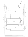
以下、パチンコ遊技機(以下、単に「パチンコ機」という)の一実施形態を、図面に基づいて詳細に説明する。図1はパチンコ機10の正面図であり、図2は、後述する外枠11と内枠12とに対して、前面枠セット14を開放し、下皿ユニット13を取り外した状態を示す斜視図である。但し、図2では便宜上、後述する遊技盤30面上の遊技領域内の構成を空白で示している。   Hereinafter, an embodiment of a pachinko gaming machine (hereinafter simply referred to as a “pachinko machine”) will be described in detail with reference to the drawings. FIG. 1 is a front view of a pachinko machine 10, and FIG. 2 is a perspective view showing a state in which a front frame set 14 is opened and a lower plate unit 13 is removed with respect to an outer frame 11 and an inner frame 12 described later. It is. However, in FIG. 2, for the sake of convenience, a configuration in a game area on the surface of the game board 30 to be described later is shown in blank.

図1,2に示すように、遊技機としてのパチンコ機10は、当該パチンコ機10の外殻を形成する外枠11を備えており、この外枠11の一側部に、内枠12が開閉可能に支持されている。外枠11は、木製の板材により全体として矩形状に構成され、小ネジ等の離脱可能な締結具により各板材が組み付けられている。従って、釘やリベットを使って各板材を組み付けていた従来構造と比べて構成部材の再利用が容易な構成となっている。本実施形態では、外枠11の上下方向の外寸は809mm(内寸771mm)、左右方向の外寸は518mm(内寸480mm)となっている。   As shown in FIGS. 1 and 2, a pachinko machine 10 as a gaming machine includes an outer frame 11 that forms an outer shell of the pachinko machine 10, and an inner frame 12 is formed on one side of the outer frame 11. It is supported so that it can be opened and closed. The outer frame 11 is formed in a rectangular shape as a whole by a wooden plate material, and each plate material is assembled by a detachable fastener such as a small screw. Therefore, the structure can be easily reused as compared with the conventional structure in which the plate members are assembled using nails and rivets. In this embodiment, the outer dimension of the outer frame 11 is 809 mm (inner dimension 771 mm), and the outer dimension in the left-right direction is 518 mm (inner dimension 480 mm).

また、内枠12及び前面枠セット14は合成樹脂、具体的にはABS(アクリロニトリル−ブタジエン−スチレン)樹脂により構成されている。両者の成形に合成樹脂を用いることにより、金属製素材を用いた場合と比較してより複雑な形状に対応できるとともに、生産コストの増大を抑制することもできる。また、ABSを用いる利点としては、ポリカーボネイト等の樹脂素材と比較して、生産コストが低い、粘性が強く衝撃に強い等が挙げられる。加えて、例えば前面枠セット14の前面側等の意匠面にメッキ等のコーティング処理を施す場合において、その処理を比較的容易に行いやすく、外観品質のより高いものが製造できるというメリットがある。   The inner frame 12 and the front frame set 14 are made of a synthetic resin, specifically, ABS (acrylonitrile-butadiene-styrene) resin. By using a synthetic resin for molding both, it is possible to cope with a more complicated shape as compared with the case of using a metal material, and it is also possible to suppress an increase in production cost. Advantages of using ABS include a low production cost, strong viscosity, and high impact resistance compared to resin materials such as polycarbonate. In addition, for example, when a coating process such as plating is performed on a design surface such as the front side of the front frame set 14, the process is relatively easy to perform, and there is an advantage that a product with higher appearance quality can be manufactured.

さて、内枠12の開閉軸線はパチンコ機10の正面からみて左側(後述するハンドル18の設置箇所の反対側)に上下に延びるように設定されており、この開閉軸線を軸心にして内枠12が前方側に開放できるようになっている。なお、外枠11は樹脂やアルミニウム等の軽金属により構成されていてもよい。   The opening / closing axis of the inner frame 12 is set so as to extend vertically to the left side (opposite to the installation position of the handle 18 described later) when viewed from the front of the pachinko machine 10, and the inner frame is centered on the opening / closing axis. 12 can be opened to the front side. The outer frame 11 may be made of a light metal such as resin or aluminum.

内枠12には、その最下部に下皿ユニット13が取り付けられると共に、下皿ユニット13を除く範囲に対応して前面枠セット14が取り付けられている。下皿ユニット13は、内枠12に対してネジ等の締結具により固定されている。また、前面枠セット14は、内枠12に対して開閉可能に取り付けられており、内枠12と同様、パチンコ機10の正面からみて左側に上下に延びる開閉軸線を軸心にして前方側に開放できるようになっている。図3は、パチンコ機10より前面枠セット14を取り外した状態を示す正面図である(但し、図3では便宜上、遊技盤30面上の遊技領域内の構成を空白で示している)。なお、内枠12の前面側には、その周囲(前面枠セット14に対応する部分)においてリブR1が突設されている。そして、前面枠セット14の閉時には、前面枠セット14がリブR1の内側に嵌まり込んだ状態となる。この構成により、前面枠セット14と内枠12との間の隙間から針金等を進入させることが困難となり、不正防止の役割を果たす。   A lower tray unit 13 is attached to the inner frame 12 at the lowermost portion, and a front frame set 14 is attached to correspond to a range excluding the lower tray unit 13. The lower plate unit 13 is fixed to the inner frame 12 with a fastener such as a screw. The front frame set 14 is attached to the inner frame 12 so as to be openable and closable. Like the inner frame 12, the front frame set 14 is located on the front side with an open / close axis extending vertically to the left when viewed from the front of the pachinko machine 10. It can be opened. FIG. 3 is a front view showing a state in which the front frame set 14 is removed from the pachinko machine 10 (however, in FIG. 3, the structure in the game area on the surface of the game board 30 is shown blank for convenience). Note that a rib R1 projects from the front side of the inner frame 12 at a periphery thereof (a portion corresponding to the front frame set 14). When the front frame set 14 is closed, the front frame set 14 is fitted into the rib R1. With this configuration, it becomes difficult to allow a wire or the like to enter from the gap between the front frame set 14 and the inner frame 12 and plays a role in preventing fraud.

下皿ユニット13には、ほぼ中央部に球受皿としての下皿15が設けられ、排出口16より排出された遊技球が下皿15内に貯留可能になっている。下皿ユニット13はその大部分が内枠12と同様、ABS樹脂にて成形されているが、その中でも特に下皿15を形成する表面層と下皿奥方の前面パネル23とは難燃性のABS樹脂にて成形されている。このため、この部分は燃え難くなっている。なお、符号24は、スピーカであり、後述する音声出力に用いられる。このスピーカ24は、パチンコ機10の左右2箇所に設けられている。また、符号25は下皿15内から遊技球を下方へと排出するための球抜きレバーである。   The lower tray unit 13 is provided with a lower tray 15 as a ball receiving tray at a substantially central portion, and the game balls discharged from the discharge port 16 can be stored in the lower tray 15. Most of the lower dish unit 13 is formed of ABS resin like the inner frame 12, but the surface layer forming the lower dish 15 and the front panel 23 at the back of the lower dish are particularly flame retardant. Molded with ABS resin. For this reason, this part is difficult to burn. Reference numeral 24 denotes a speaker, which is used for audio output to be described later. The speakers 24 are provided at two places on the left and right sides of the pachinko machine 10. Reference numeral 25 denotes a ball release lever for discharging the game ball from the lower plate 15 downward.

下皿15よりも右方には、手前側に突出して遊技球発射ハンドル(以下単に「ハンドル」という)18が配設されている。つまり、ハンドル18は、内枠12の開閉軸線とは反対側にあたるパチンコ機10の正面からみて右側に位置しており、ハンドル18の突出に関わりなく内枠12の開放時における所定の開放量を確保できる。また、下皿15の左方には、灰皿26が設けられている。なお、灰皿26は、下皿15の左側辺部より左方へ突出した図示しない軸棒によって回動可能に支持された、いわゆる片持ち構造となっている。   A game ball launching handle (hereinafter simply referred to as “handle”) 18 is disposed on the right side of the lower plate 15 so as to protrude to the front side. That is, the handle 18 is positioned on the right side when viewed from the front of the pachinko machine 10 on the side opposite to the opening / closing axis of the inner frame 12, and a predetermined opening amount when the inner frame 12 is opened regardless of the protrusion of the handle 18. It can be secured. An ashtray 26 is provided on the left side of the lower plate 15. The ashtray 26 has a so-called cantilever structure that is rotatably supported by a shaft rod (not shown) protruding leftward from the left side of the lower tray 15.

一方、下皿15の上方において球受皿としての上皿19が設けられている。ここで、上皿19は、遊技球を一旦貯留し、一列に整列させながら遊技球発射装置の方へ導出するための球受皿である。なお、上皿19は、前面枠セット14において、ガラスを支持するガラス枠部と一体的に形成されている。従来のパチンコ機ではガラス枠の下方の内枠に対し開閉可能な前飾り枠が設けられ、該前飾り枠に上皿が設けられていたのであるが、本実施形態では前面枠セット14に対し直接的かつ一体的に上皿19が設けられているため、後述するように前面枠セット14のフレーム部分の幅が従来に比べ比較的細いものであっても、前面枠セット14(ガラス枠部)の所定の強度を確保することができる。この上皿19も下皿15と同様、表面層が難燃性のABS樹脂にて成形される構成となっている。   On the other hand, an upper plate 19 serving as a ball receiving plate is provided above the lower plate 15. Here, the upper tray 19 is a ball receiving tray for temporarily storing the game balls and guiding them to the game ball launching device while aligning them in a line. The upper plate 19 is integrally formed with the glass frame portion that supports the glass in the front frame set 14. In the conventional pachinko machine, a front decorative frame that can be opened and closed with respect to the inner frame below the glass frame is provided, and an upper plate is provided on the front decorative frame. Since the upper plate 19 is provided directly and integrally, even if the width of the frame portion of the front frame set 14 is relatively narrow as compared with the prior art, as will be described later, the front frame set 14 (glass frame portion) ) Can be ensured. Similar to the lower plate 15, the upper plate 19 has a structure in which the surface layer is formed of flame-retardant ABS resin.

また、図3において、内枠12は、外形が矩形状の樹脂ベース20を主体に構成されており、樹脂ベース20の中央部には略円形状の窓孔21が形成されている。樹脂ベース20の後側には遊技盤30が着脱可能に装着されている。遊技盤30は四角形状の合板よりなり、その周縁部が樹脂ベース20(内枠12)の裏側に当接した状態で取着されている。従って、遊技盤30の前面部の略中央部分が樹脂ベース20の窓孔21を通じて内枠12の前面側に露出した状態となっている。なお、遊技盤30の上下方向の長さは476mm、左右方向の長さは452mmとなっている(従来と同等サイズ)。なお、樹脂ベース20には、前面枠セット14の開放を検知する開放検知センサ22が設けられている。また、図示しないが内枠12の開放を検知する開放検知スイッチも設けられている。   In FIG. 3, the inner frame 12 is mainly composed of a resin base 20 having a rectangular outer shape, and a substantially circular window hole 21 is formed at the center of the resin base 20. A game board 30 is detachably mounted on the rear side of the resin base 20. The game board 30 is made of a rectangular plywood and is attached in a state in which the peripheral edge thereof is in contact with the back side of the resin base 20 (inner frame 12). Accordingly, the substantially central portion of the front surface portion of the game board 30 is exposed to the front surface side of the inner frame 12 through the window hole 21 of the resin base 20. The game board 30 has a vertical length of 476 mm and a horizontal length of 452 mm (same size as before). The resin base 20 is provided with an opening detection sensor 22 that detects opening of the front frame set 14. Although not shown, an open detection switch for detecting the opening of the inner frame 12 is also provided.

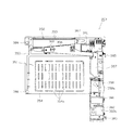
次に、遊技盤30の構成を、図4を用いて説明する。遊技盤30には、入球手段としての一般入賞口31、入球手段としての可変入賞装置32、入球手段としての第1契機対応口(始動口)33、入球手段としての第2契機対応口(スルーゲート)34、可変表示装置ユニット35等がルータ加工によって形成された貫通穴に配設され、遊技盤30前面側から木ネジ等により取付けられている。周知の通り前記一般入賞口31、可変入賞装置32、第1契機対応口33に遊技球が入球し、後述する検出スイッチの出力により、上皿19(または下皿15)へ所定数の賞球が払い出される。その他に、遊技盤30にはアウト口36が設けられており、各種入賞部(入賞装置、入賞口、第1契機対応口33等)に入球しなかった遊技球はこのアウト口36を通って図示しない球排出路の方へと案内されるようになっている。遊技盤30には、遊技球の落下方向を適宜分散、調整等するために多数の釘が植設されているとともに、風車27等の各種部材(役物)が配設されている。   Next, the configuration of the game board 30 will be described with reference to FIG. The game board 30 has a general winning opening 31 as a winning means, a variable winning device 32 as a winning means, a first opportunity corresponding opening (starting opening) 33 as a winning means, and a second opportunity as a winning means. A corresponding port (through gate) 34, a variable display device unit 35, and the like are disposed in a through hole formed by router processing, and are attached from the front side of the game board 30 with wood screws or the like. As is well known, a game ball enters the general winning opening 31, the variable winning apparatus 32, and the first opportunity corresponding opening 33, and a predetermined number of prizes are given to the upper plate 19 (or the lower plate 15) by the output of a detection switch described later. The ball is paid out. In addition, the game board 30 is provided with an out port 36, and game balls that have not entered the various winning units (winning device, winning port, first opportunity corresponding port 33, etc.) pass through the out port 36. Then, it is guided toward a ball discharge path (not shown). A number of nails are planted on the game board 30 in order to appropriately disperse and adjust the falling direction of the game balls, and various members (functions) such as the windmill 27 are arranged.

可変表示装置ユニット35には、第2契機対応口34の通過を契機として第2図柄を変動表示する第2図柄表示装置41と、第1契機対応口33への入賞を契機として識別情報としての第1図柄(特別図柄)を変動表示する図柄表示装置としての第1図柄表示装置42(特別図柄表示装置)とが設けられている。第2図柄表示装置41(普通図柄表示装置)は、第2図柄(普通図柄)用の表示部43と保留ランプ44とを有し、遊技球が第2契機対応口34を通過する毎に例えば表示部43による表示図柄(第2図柄)が変動し、その変動表示が所定図柄で停止した場合に第1契機対応口33が所定時間だけ作動状態となる(開放される)よう構成されている。第2図柄表示装置41の表示部43における第2図柄の変動表示中に、新たに遊技球が第2契機対応口34を通過した場合には、その分の第2図柄の変動表示は、その時点で行われている変動表示の終了後に行われる構成となっている。つまり、変動表示が待機(保留)されることとなる。この保留される変動表示の最大回数は、パチンコ機の機種毎に決められているが、本実施形態では4回まで保留され、その保留回数が保留ランプ44にて点灯表示されるようになっている。しかし、かかる最大保留回数は、これに限定されるものではない。例えば、8回分の第2図柄の変動表示を待機させるべく、最大保留回数を8回に設定することとしてもよい。なお、表示部43は、複数のランプの点灯を切り換えることにより変動表示される構成の他、第1図柄表示装置42(液晶表示装置)の一部で変動表示される構成等であっても良い。保留ランプ44も同様に、第1図柄表示装置42の一部で変動表示される構成等であっても良い。   The variable display device unit 35 has identification information as a second symbol display device 41 that displays the second symbol variably with the passage of the second trigger corresponding port 34 and a winning at the first trigger corresponding port 33 as a trigger. A first symbol display device 42 (special symbol display device) is provided as a symbol display device that variably displays the first symbol (special symbol). The second symbol display device 41 (ordinary symbol display device) includes a display portion 43 for a second symbol (ordinary symbol) and a holding lamp 44, and each time a game ball passes through the second opportunity corresponding port 34, for example, When the display symbol (second symbol) by the display unit 43 fluctuates and the variation display stops at a predetermined symbol, the first opportunity corresponding port 33 is configured to be in an activated state (opened) for a predetermined time. . When a game ball newly passes through the second opportunity corresponding port 34 during the second symbol variation display on the display unit 43 of the second symbol display device 41, the variation variation display of the second symbol is It is configured to be performed after the end of the variable display performed at the time. That is, the variable display is on standby (held). The maximum number of the variable display to be held is determined for each model of the pachinko machine, but in this embodiment, it is held up to 4 times, and the hold number is lit and displayed by the hold lamp 44. Yes. However, the maximum number of holding times is not limited to this. For example, the maximum hold count may be set to 8 in order to wait for the second symbol variation display for 8 times. The display unit 43 may be configured to be variably displayed by a part of the first symbol display device 42 (liquid crystal display device) in addition to the configuration to be variably displayed by switching lighting of a plurality of lamps. . Similarly, the hold lamp 44 may be configured to be variably displayed on a part of the first symbol display device 42.

第1図柄表示装置42は液晶表示装置として構成されており、後述する表示制御装置45により表示内容が制御される。第1図柄表示装置42には、例えば上、中及び下の3つの図柄列が表示される。各図柄列は複数の図柄によって構成されており、これら図柄が図柄列毎にスクロールされるようにして第1図柄表示装置42に可変表示されるようになっている。なお本実施形態では、第1図柄表示装置42(液晶表示装置)は8インチサイズの大型の液晶ディスプレイを備える。可変表示装置ユニット35には、第1図柄表示装置42を囲むようにしてセンターフレーム47が配設されている。   The first symbol display device 42 is configured as a liquid crystal display device, and the display content is controlled by a display control device 45 described later. The first symbol display device 42 displays three symbol rows, for example, upper, middle, and lower. Each symbol row is composed of a plurality of symbols, and these symbols are variably displayed on the first symbol display device 42 so as to be scrolled for each symbol row. In the present embodiment, the first symbol display device 42 (liquid crystal display device) includes a large liquid crystal display of 8 inches. The variable display device unit 35 is provided with a center frame 47 so as to surround the first symbol display device 42.

可変入賞装置32は、通常は遊技球が入賞できない又は入賞し難い閉状態になっており、大当たり(特別遊技状態の発生)の際に遊技球が入賞しやすい開状態と通常の閉状態とに繰り返し作動されるようになっている。より詳しくは、第1契機対応口33に対し遊技球が入賞すると第1図柄表示装置42で図柄が変動表示され、その停止後の確定図柄が予め設定した特定の図柄の組合せとなったことを必要条件に特別遊技状態が発生する。そして、可変入賞装置32の大入賞口が所定の開放状態となり、遊技球が入賞しやすい状態(大当たり状態)になるよう構成されている。具体的には、所定時間の経過又は所定個数の入賞を1ラウンドとして、可変入賞装置32の大入賞口が所定回数繰り返し開放される。第1図柄表示装置42の図柄変動表示中に新たに遊技球が第1契機対応口33に入賞した場合には、その分の図柄変動表示は、その時点で行われている図柄変動表示の終了後に行われる構成となっている。つまり、図柄変動表示が待機(保留、記憶)されることとなる(記憶手段)。この保留される図柄変動表示の最大回数は、パチンコ機の機種毎に決められているが、本実施形態では4回まで保留され、その保留回数が保留ランプ46にて点灯表示されるようになっている。しかし、最大保留回数は、これに限定されるものではない。例えば、8回分の図柄変動表示を待機させるべく、最大保留回数を8回に設定することとしてもよい。なお、保留ランプ46は、第1図柄表示装置42の一部で変動表示される構成等であっても良い。   The variable winning device 32 is normally in a closed state in which a game ball cannot be won or difficult to win, and is in an open state in which a game ball is likely to win in a big hit (occurrence of a special game state) and a normal closed state. It is designed to be operated repeatedly. More specifically, when a game ball wins the first opportunity corresponding port 33, the symbols are displayed in a variable manner on the first symbol display device 42, and the confirmed symbol after the stop is a combination of specific symbols set in advance. A special gaming state occurs as a necessary condition. The large winning opening of the variable winning device 32 is in a predetermined open state, and the game ball is configured to be in a state where it is easy to win a prize (a big hit state). Specifically, the passage of a predetermined time or a predetermined number of winnings is defined as one round, and the big winning opening of the variable winning device 32 is repeatedly opened a predetermined number of times. When a new game ball wins the first opportunity corresponding port 33 during the symbol variation display of the first symbol display device 42, the symbol variation display for that time is the end of the symbol variation display being performed at that time. The configuration is performed later. That is, the symbol variation display is waited (held, stored) (storage means). Although the maximum number of symbol variation displays to be held is determined for each model of the pachinko machine, in this embodiment, it is held up to 4 times, and the number of times of holding is lit and displayed by the hold lamp 46. ing. However, the maximum number of holding times is not limited to this. For example, the maximum number of suspensions may be set to 8 in order to wait for 8 symbol fluctuation displays. Note that the hold lamp 46 may be configured so as to be variably displayed on a part of the first symbol display device 42.

また、遊技盤30には、遊技球発射装置から発射された遊技球を遊技盤30上部へ案内するためのレールユニット50が取り付けられており、ハンドル18の回動操作に伴い発射された遊技球はレールユニット50を通じて所定の遊技領域に案内されるようになっている。レールユニット50はリング状をなす樹脂成形品にて構成されており、内外二重に一体形成された内レール構成部(内レール部)51と外レール構成部(外レール取付け部)52とを有する。内レール構成部51は上方の約1/4ほどを除いて略円環状に形成されている。また、一部(主に左側部)が内レール構成部51に向かい合うようにして外レール構成部52が形成されている。かかる場合、内レール構成部51と外レール構成部52とにより主として誘導レールが構成され、これら各レール構成部51,52が所定間隔を隔てて並行する部分(向かって左側の部分)により球案内通路が形成されている。なお、球案内通路は、遊技盤30との当接面を有した溝状、すなわち手前側を開放した溝状に形成されている。   Further, the game board 30 is provided with a rail unit 50 for guiding the game balls launched from the game ball launching device to the upper part of the game board 30, and the game balls launched by the turning operation of the handle 18. Are guided to a predetermined game area through the rail unit 50. The rail unit 50 is formed of a ring-shaped resin molded product, and includes an inner rail constituent part (inner rail part) 51 and an outer rail constituent part (outer rail mounting part) 52 that are integrally formed in an inner and outer double. Have. The inner rail constituting portion 51 is formed in a substantially annular shape except for about 1/4 of the upper portion. Further, the outer rail constituting portion 52 is formed so that a part (mainly the left side portion) faces the inner rail constituting portion 51. In such a case, the inner rail constituting portion 51 and the outer rail constituting portion 52 mainly constitute a guide rail, and each of the rail constituting portions 51 and 52 is guided by a ball by a portion (left portion toward the left) that is parallel with a predetermined interval. A passage is formed. The ball guide passage is formed in a groove shape having a contact surface with the game board 30, that is, a groove shape in which the front side is opened.

内レール構成部51の先端部分(図4の左上部)には戻り球防止部材53が取着されている。これにより、一旦、内レール構成部51及び外レール構成部52間の球案内通路から遊技盤30の上部へと案内された遊技球が再度球案内通路内に戻ってしまうといった事態が防止されるようになっている。また、外レール構成部52には、遊技球の最大飛翔部分に対応する位置(図4の右上部:外レール構成部52の先端部に相当する部位)に返しゴム54が取着されている。従って、所定以上の勢いで発射された遊技球は、返しゴム54に当たって例えば遊技盤30の略中央部側へ戻される。外レール構成部52の内側面には、遊技球の飛翔をより滑らかなものとするべく、長尺状をなすステンレス製の金属帯としての摺動プレート55が取着されている。なお、本実施形態では、外レール構成部52及び摺動プレート55によって、いわゆる従来の外レールに相当するものが構成されている。そして、内外レール構成部51,52及び摺動プレート55をレールユニット50としてユニット化することにより、従来の内外レールを別々に設けた構成に比べて、取付け作業が容易となり作業性が向上する。   A return ball preventing member 53 is attached to the tip portion of the inner rail constituting portion 51 (the upper left portion in FIG. 4). This prevents a situation in which the game ball once guided from the ball guide passage between the inner rail constituting portion 51 and the outer rail constituting portion 52 to the upper portion of the game board 30 returns to the ball guide passage again. It is like that. Further, a return rubber 54 is attached to the outer rail constituting portion 52 at a position corresponding to the maximum flight portion of the game ball (upper right portion in FIG. 4: a portion corresponding to the tip portion of the outer rail constituting portion 52). . Therefore, the game ball launched at a predetermined momentum or more hits the return rubber 54 and is returned to, for example, the substantially central portion side of the game board 30. On the inner side surface of the outer rail constituting portion 52, a sliding plate 55 is attached as a long metal strip made of stainless steel so that the flight of the game ball is smoother. In the present embodiment, the outer rail constituting portion 52 and the sliding plate 55 constitute a so-called conventional outer rail. Then, by making the inner and outer rail components 51 and 52 and the sliding plate 55 into a unit as the rail unit 50, the mounting operation becomes easier and the workability is improved as compared with the conventional configuration in which the inner and outer rails are separately provided.

また、レールユニット50の外周部には、外方へ張り出した円弧状のフランジ56が形成されている。フランジ56は、遊技盤30に対する取付面を構成する。レールユニット50が遊技盤30に取り付けられる際には、遊技盤30上にフランジ56が当接され、その状態で、当該フランジ56に形成された複数の透孔にネジNJ等の固定手段が挿通されて遊技盤30に対するレールユニット50の締結がなれるようになっている。さらに本実施形態では、正面から見てレールユニット50の上下左右の各端部は略直線状に(平坦に)形成されている。つまり、レールユニット50の上下左右の各端部においてはフランジ56が切り落とされ、パチンコ機10における有限の領域にてレール径の拡張、すなわち遊技盤30上の遊技領域の拡張が図られるようになっている。なお、左下のフランジ56においては他の部分(左上部,右上部及び右下部のフランジ56)と比較して、より多く固定手段が使用されている。これは、上記誘導レール及び球案内通路の位置をより適正な位置に固定するためであり、これにより遊技球発射装置から発射された遊技球がより安定して遊技盤30上部へ案内される。加えて、固定手段の数を増やすことでレールユニット50をより強固に固定でき、仮にレールユニット50の成形時において歪みが生じたとしても、その歪みを吸収する効果がある。   An arc-shaped flange 56 projecting outward is formed on the outer peripheral portion of the rail unit 50. The flange 56 constitutes a mounting surface for the game board 30. When the rail unit 50 is attached to the game board 30, the flange 56 is brought into contact with the game board 30, and in this state, fixing means such as screws NJ are inserted into the plurality of through holes formed in the flange 56. Thus, the rail unit 50 can be fastened to the game board 30. Further, in the present embodiment, the top, bottom, left, and right ends of the rail unit 50 are formed substantially linearly (flatly) when viewed from the front. That is, the flange 56 is cut off at each of the upper, lower, left, and right ends of the rail unit 50, so that the rail diameter can be expanded in a limited area in the pachinko machine 10, that is, the game area on the game board 30 can be expanded. ing. The lower left flange 56 uses more fixing means than the other parts (upper left, upper right and lower right flanges 56). This is for fixing the positions of the guide rail and the ball guide passage to more appropriate positions, whereby the game ball launched from the game ball launching device is more stably guided to the upper part of the game board 30. In addition, the rail unit 50 can be more firmly fixed by increasing the number of fixing means, and even if distortion occurs when the rail unit 50 is molded, there is an effect of absorbing the distortion.

内レール構成部51及び外レール構成部52間の球案内通路の入口には、同球案内通路の一部を閉鎖するようにして凸部57が形成されている。この凸部57は、内レール構成部51からレールユニット50下端部にかけて略鉛直方向に設けられ、遊技領域まで至らず球案内通路内を逆流してくるファール球をファール球通路63(図3参照)に導くための役目をなす。なお、遊技盤30の右下隅部及び左下隅部は、証紙等のシールやプレート(図のS1,S2)を貼着するためのスペースとなっており、この貼着スペースを確保するために、フランジ56に切欠58,59が形成されている。   A convex portion 57 is formed at the entrance of the spherical guide passage between the inner rail constituting portion 51 and the outer rail constituting portion 52 so as to close a part of the spherical guide passage. This convex portion 57 is provided in a substantially vertical direction from the inner rail constituting portion 51 to the lower end portion of the rail unit 50, and a foul ball that does not reach the game area and flows backward in the ball guide passage is used as a foul ball passage 63 (see FIG. 3). ). Note that the lower right corner and the lower left corner of the game board 30 are spaces for attaching seals and plates (S1, S2 in the figure) such as certificate stamps, in order to secure this attachment space. Notches 58 and 59 are formed in the flange 56.

次に、遊技領域について説明する。遊技領域は、レールユニット50の内周部(内外レール構成部51,52)により略円形状に区画形成されており、特に本実施形態では、遊技盤30の盤面上に区画される遊技領域が従来よりもはるかに大きく構成されている。本実施形態では、外レール構成部52の最上部地点から遊技盤30下部までの間の距離は445mm(従来品よりも58mm長い)、外レール構成部52の極左位置から内レール構成部51の極右位置までの間の距離は435mm(従来品よりも50mm長い)となっている。また、内レール構成部51の極左位置から内レール構成部51の極右位置までの間の距離は418mmとなっている。   Next, the game area will be described. The game area is partitioned and formed in a substantially circular shape by the inner periphery (inner and outer rail components 51 and 52) of the rail unit 50. In particular, in this embodiment, the game area partitioned on the board surface of the game board 30 is It is much larger than before. In the present embodiment, the distance between the uppermost point of the outer rail component 52 and the lower part of the game board 30 is 445 mm (58 mm longer than the conventional product), and the inner rail component 51 has a distance from the extreme left position of the outer rail component 52. The distance to the extreme right position is 435 mm (50 mm longer than the conventional product). The distance from the extreme left position of the inner rail component 51 to the extreme right position of the inner rail component 51 is 418 mm.

本実施形態では、遊技領域を、パチンコ機10の正面から見て、内レール構成部51及び外レール構成部52によって囲まれる領域のうち、内外レール構成部51,52の並行部分である誘導レールの領域を除いた領域としている。従って、遊技領域と言った場合には誘導レール部分は含まないため、遊技領域の向かって左側限界位置は外レール構成部52によってではなく内レール構成部51によって特定される。同様に、遊技領域の向かって右側限界位置は内レール構成部51によって特定される。また、遊技領域の下側限界位置は遊技盤30の下端位置によって特定される。また、遊技領域の上側限界位置は外レール構成部52によって特定される。   In the present embodiment, when the game area is viewed from the front of the pachinko machine 10, a guide rail that is a parallel part of the inner and outer rail constituting parts 51 and 52 in the area surrounded by the inner rail constituting part 51 and the outer rail constituting part 52. This area is excluded from the above area. Therefore, since the game area does not include the guide rail portion, the left limit position toward the game area is specified not by the outer rail component 52 but by the inner rail component 51. Similarly, the right limit position toward the game area is specified by the inner rail constituting unit 51. The lower limit position of the game area is specified by the lower end position of the game board 30. Further, the upper limit position of the game area is specified by the outer rail component 52.

従って、本実施形態では、遊技領域の幅(左右方向の最大幅)は、418mmであり、遊技領域の高さ(上下方向の最大幅)は、445mmである。   Therefore, in the present embodiment, the width of the game area (maximum width in the left-right direction) is 418 mm, and the height of the game area (maximum width in the vertical direction) is 445 mm.

ここで、前記遊技領域の幅は、少なくとも380mm以上あることが望ましい。より好ましくは390mm以上、400mm以上、410mm以上、420mm以上、430mm以上、440mm以上、450mm以上、さらに460mm以上であることが望ましい。もちろん、470mm以上であってもよい。すなわち、遊技領域の幅は、遊技領域拡大という観点からは大きい程好ましい。また、遊技領域の高さは、少なくとも400mm以上あることが望ましい。より好ましくは410mm以上、420mm以上、430mm以上、440mm以上、450mm以上、さらには460mm以上であることがより望ましい。もちろん、470mm以上、480mm以上、490mm以上としてもよい。すなわち、遊技領域の幅は、遊技領域拡大という観点からは大きい程好ましい。なお、上記幅及び高さの組合せについては、上記数値を任意に組み合わせたものとしてもよい。   Here, the width of the gaming area is preferably at least 380 mm. More preferably, it is 390 mm or more, 400 mm or more, 410 mm or more, 420 mm or more, 430 mm or more, 440 mm or more, 450 mm or more, and further 460 mm or more. Of course, it may be 470 mm or more. That is, the width of the game area is preferably as large as possible from the viewpoint of expanding the game area. The height of the game area is preferably at least 400 mm. More preferably, it is 410 mm or more, 420 mm or more, 430 mm or more, 440 mm or more, 450 mm or more, and more preferably 460 mm or more. Of course, it is good also as 470 mm or more, 480 mm or more, and 490 mm or more. That is, the width of the game area is preferably as large as possible from the viewpoint of expanding the game area. In addition, about the combination of the said width | variety and height, it is good also as what combined the said numerical value arbitrarily.

本実施形態では、遊技盤30面に対する遊技領域の面積の比率は約70%と、従来に比べ格段に面積比が大きいものとなっている。なお、遊技盤30面に対する遊技領域の面積比は、従来では50%程度に過ぎなかったことから、遊技盤30を共通とした前提においてはかなり遊技領域を拡大しているといえる。尚、パチンコ機10の外形は遊技場への設置の都合上製造者間でほぼ統一されており、遊技盤30の大きさも同様とせざるを得ない状況下において、上記のように遊技盤30面に対する遊技領域の面積の比率を約20%も高めたことは、遊技領域拡大の観点で非常に有意義である。ここで、前記比率は、少なくとも60%以上であることが望ましい。さらに好ましくは65%以上であり、より好ましくは70%以上である。また、本実施形態の場合を越えて75%以上であれば、一層望ましい。さらには、80%以上であってもよい。   In the present embodiment, the ratio of the area of the game area to the surface of the game board 30 is about 70%, which is a much larger area ratio than before. Note that the area ratio of the game area to the surface of the game board 30 is only about 50% in the past, so it can be said that the game area is considerably expanded on the premise that the game board 30 is shared. It should be noted that the external shape of the pachinko machine 10 is almost uniform among manufacturers for the convenience of installation in the game hall, and in the situation where the size of the game board 30 must be the same, the surface of the game board 30 as described above. Increasing the ratio of the area of the gaming area to about 20% is very significant from the viewpoint of expanding the gaming area. Here, the ratio is preferably at least 60% or more. More preferably, it is 65% or more, More preferably, it is 70% or more. Further, if it is 75% or more exceeding the case of this embodiment, it is more desirable. Furthermore, it may be 80% or more.

また、パチンコ機10全体の正面側の面積に対する遊技領域の面積の比率は約40%と、従来に比べ格段に面積比が大きいものとなっている。なお、パチンコ機10全体の正面側の面積に対する遊技領域の面積比は、35パーセント以上であるのが望ましい。もちろん、40パーセント以上としてもよいし、45パーセント以上、又は50パーセント以上としてもよい。   Moreover, the ratio of the area of the game area to the area of the front side of the entire pachinko machine 10 is about 40%, which is a much larger area ratio than before. The area ratio of the game area to the area on the front side of the entire pachinko machine 10 is desirably 35% or more. Of course, it may be 40% or more, 45% or more, or 50% or more.

なお、可変表示装置ユニット35の両側に位置する第2契機対応口34は、該第2契機対応口34を通過した遊技球が中央の方へ寄せられるような案内機構を有している。これにより、遊技領域が左右方向に拡張されている場合であっても、遊技球を中央の第1契機対応口33や可変入賞装置32の方へと案内することができ、ひいては、遊技領域が拡張されることにより遊技球が入賞しにくくなることによる興趣の低下が抑制されるようになっている。さらには、遊技領域が左右方向に拡張されていることによって、第2契機対応口34、風車27、複数の釘(遊技球を中央に誘導するための誘導釘)、他の役物を種々配設することができ、可変表示装置ユニット35の左右両側の遊技領域での遊技球の挙動を一層面白くすることができるようになっている。また、遊技領域が上下方向にも拡張されていることから、さらに第2契機対応口34、風車27、複数の釘、他の役物を種々配設することができ、遊技領域での上下方向の遊技球の挙動をより一層面白くすることができるようになっている。   In addition, the 2nd opportunity corresponding | compatible opening 34 located in the both sides of the variable display apparatus unit 35 has a guide mechanism in which the game ball which passed this 2nd opportunity corresponding | compatible opening 34 is approached toward the center. As a result, even when the game area is expanded in the left-right direction, the game ball can be guided toward the first first opportunity corresponding port 33 and the variable winning device 32. By expanding, it is possible to suppress a decrease in interest due to difficulty in winning a game ball. Furthermore, the game area is expanded in the left-right direction, so that the second opportunity corresponding port 34, the windmill 27, a plurality of nails (guide nails for guiding the game ball to the center), and various other objects are arranged. The behavior of the game ball in the game areas on the left and right sides of the variable display device unit 35 can be made more interesting. In addition, since the gaming area is also expanded in the vertical direction, the second opportunity corresponding port 34, the windmill 27, a plurality of nails, and other accessories can be arranged in various ways. The behavior of the game ball can be made even more interesting.

図3の説明に戻り、前記樹脂ベース20において、窓孔21(遊技盤30)の下方には、遊技球発射装置より発射された直後に遊技球を案内するための発射レール61が取り付けられている。発射レール61は、その後方の金属板62と一体的に樹脂ベース20に取付固定されており、所定の発射角度(打ち出し角度)にて直線的に延びるよう構成されている。従って、ハンドル18の回動操作に伴い発射された遊技球は、まずは発射レール61に沿って斜め上方に打ち出され、その後前述した通りレールユニット50の球案内通路を通じて所定の遊技領域に案内されるようになっている。   Returning to the description of FIG. 3, in the resin base 20, below the window hole 21 (game board 30), a launch rail 61 for guiding the game ball immediately after being launched from the game ball launcher is attached. Yes. The firing rail 61 is fixedly attached to the resin base 20 integrally with the metal plate 62 behind the firing rail 61, and is configured to extend linearly at a predetermined firing angle (launch angle). Accordingly, the game ball that is launched in accordance with the turning operation of the handle 18 is first launched obliquely upward along the launch rail 61 and then guided to a predetermined game area through the ball guide passage of the rail unit 50 as described above. It is like that.

本パチンコ機10の場合、遊技領域が従来よりも大幅に拡張されることは既に述べたが、かかる構成下では、誘導レールの曲率を小さくせざるを得ないことから、打出球を安定化させるための工夫を要する。そこで本実施形態では、遊技球の発射位置を低くするとともに発射レール61の傾斜角度(発射角度)を既存のものよりも幾分大きくし(すなわち発射レール61を立ち上げるようにし)、さらに発射レール61の長さを既存のものよりも長くして十分な長さの球誘導距離を確保するようにしている。これにより、遊技球発射装置から発射された遊技球をより安定した状態で誘導レールに案内できるようにしている。この場合特に、発射レール61を、遊技球発射装置の発射位置から遊技領域の左右方向の中央位置(アウト口36)を越える位置まで延びるよう形成している。また、発射レール61を上記構成とするため、本実施形態では金属板62も従来のものより比較的大きなものとし、それを固定する固定手段の数も従来に比べ多くしている。   In the case of this pachinko machine 10, it has already been described that the game area is greatly expanded compared to the conventional case, but under such a configuration, the curvature of the guide rail must be reduced, so that the launch ball is stabilized. Need some ingenuity. Therefore, in this embodiment, the launch position of the game ball is lowered, the inclination angle (launch angle) of the launch rail 61 is made somewhat larger than the existing one (that is, the launch rail 61 is raised), and the launch rail is further increased. The length of 61 is made longer than the existing one so as to ensure a sufficiently long ball guiding distance. Thereby, the game ball launched from the game ball launching device can be guided to the guide rail in a more stable state. In this case, in particular, the launch rail 61 is formed so as to extend from the launch position of the game ball launcher to a position beyond the center position (out port 36) in the left-right direction of the game area. In addition, since the launch rail 61 has the above-described configuration, in this embodiment, the metal plate 62 is also relatively larger than the conventional one, and the number of fixing means for fixing the metal plate 62 is larger than the conventional one.

また、発射レール61とレールユニット50(誘導レール)との間には所定間隔の隙間があり、この隙間より下方にファール球通路63が形成されている。従って、仮に、遊技球発射装置から発射された遊技球が戻り球防止部材53まで至らずファール球として誘導レール内を逆戻りする場合には、そのファール球がファール球通路63を介して下皿15に排出される。因みに、本実施形態の場合、発射レール61の長さは約240mm、発射レール先端部の隙間の長さ(発射レール61の延長線上の長さ)は約40mmである。   In addition, there is a predetermined gap between the firing rail 61 and the rail unit 50 (guide rail), and a foul ball passage 63 is formed below the gap. Therefore, if the game ball fired from the game ball launching device does not reach the return ball prevention member 53 and returns to the inside of the guide rail as a foul ball, the foul ball passes through the foul ball path 63 to the lower plate 15. To be discharged. Incidentally, in the present embodiment, the length of the firing rail 61 is about 240 mm, and the length of the gap at the tip of the firing rail (the length on the extension line of the firing rail 61) is about 40 mm.

ファール球が誘導レール内を逆流してくる際、その多くは外レール構成部52に沿って流れ、外レール構成部52の下端部に到達した時点で下方に落下するが、一部のファール球は誘導レール内で暴れ、内レール構成部51側へ跳ね上がるものもある。この際、跳ね上がったファール球は、球案内通路入口の前記凸部57に当たり、ファール球通路63に誘導される。これにより、ファール球の全てがファール球通路63に確実に案内されるようになる。これにより、ファール球と次に発射される遊技球との干渉が抑制される。   When the foul sphere flows backward in the guide rail, most of the foul sphere flows along the outer rail constituting portion 52 and drops downward when reaching the lower end portion of the outer rail constituting portion 52. May be ramped in the guide rail and jump to the inner rail component 51 side. At this time, the splashed foul ball hits the convex portion 57 at the entrance of the ball guide passage and is guided to the foul ball passage 63. Thereby, all of the foul balls are surely guided to the foul ball passage 63. This suppresses interference between the foul ball and the next game ball to be launched.

なお、詳しい図面の開示は省略するが、遊技球発射装置には、前面枠セット14側の球出口(上皿19の最下流部より通じる球出口)から遊技球が1つずつ供給される。この際、本実施形態では遊技球の発射位置を低くしたため、前面枠セット14側の球出口から前記発射位置への落差が大きくなるが、発射レール61の基端部付近にはその右側と手前側にそれぞれガイド部材65,66を設置している。これにより、前面枠セット14側の球出口から供給される遊技球が常に所定の発射位置にセットされ、安定した発射動作が実現できる。また、遊技球発射装置には打球槌が設けられ、軸部を中心とする打球槌の回動に伴い遊技球が発射されるが、打球槌に関して軽量化が望まれている。それ故、アルミニウム等の軽金属への材料変更や軸部寸法の縮小化により打球槌の軽量化を図る一方で、十分な発射力を確保すべく、打球槌のヘッド部(軸部と反対側の端部)に重り部を設けている。これにより、十分でかつ安定した遊技球の発射が実現できる。打球槌の重り部を上方に突出して設けることにより、打球槌を容易に摘んだりひっかけたりすることができ、槌先の打球強さの調整等がし易くなるという効果がある。   Although detailed disclosure of the drawings is omitted, one game ball is supplied to the game ball launching device one by one from the ball outlet on the front frame set 14 side (ball outlet leading from the most downstream portion of the upper plate 19). At this time, since the launch position of the game ball is lowered in this embodiment, a drop from the exit of the ball on the front frame set 14 side to the launch position becomes large, but the right side and the near side of the launch rail 61 are near the base end portion. Guide members 65 and 66 are provided on the sides. Thereby, the game ball supplied from the ball exit on the front frame set 14 side is always set at a predetermined launch position, and a stable launch operation can be realized. Further, the game ball launching device is provided with a hitting ball, and the game ball is shot with the rotation of the hitting ball around the shaft portion. However, the weight reduction of the hitting ball is desired. Therefore, while aiming to reduce the weight of the hitting ball by changing the material to light metal such as aluminum and reducing the size of the shaft, the head of the hitting ball (on the opposite side of the shaft) is secured to ensure sufficient firing force. A weight is provided at the end. Thereby, sufficient and stable launch of the game ball can be realized. By providing the weight portion of the hitting ball projecting upward, the hitting ball can be easily picked up or caught, and it is easy to adjust the hitting ball strength of the tip.

なお、図3中の符号67は上皿19に通ずる排出口であり、この排出口67を介して遊技球が上皿19に排出される。排出口67には開閉式のシャッタ68が取り付けられている。詳しい図面の開示は省略するが、シャッタ68は、その下辺部に沿って設けられた軸部を軸心として回動可能となるとともに、前面枠セット14を開放した状態(図3の状態)ではバネ等の付勢力によりシャッタ68が排出口67をほぼ閉鎖するようになっている。また、前面枠セット14を閉鎖した状態では、当該前面枠セット14の裏面に設けられた球通路樋69(図2参照)によりシャッタ68が押し開けられるようになっている。なお、前面枠セット14の開放状態においては、遊技球は下皿15へ排出されるようになっている。従って、上述したように、前面枠セット14に対して上皿19が直接設けられる構成とした本パチンコ機10において、前面枠セット14の開放に際し払出通路内等の遊技球がこぼれ落ちてしまうといった不都合が防止できるようになっている。   In addition, the code | symbol 67 in FIG. 3 is the discharge port connected to the upper plate 19, and a game ball is discharged to the upper plate 19 through this discharge port 67. FIG. An open / close shutter 68 is attached to the discharge port 67. Although detailed disclosure of the drawings is omitted, the shutter 68 is rotatable about the shaft portion provided along the lower side portion thereof, and is in a state where the front frame set 14 is opened (state of FIG. 3). The shutter 68 substantially closes the discharge port 67 by a biasing force such as a spring. When the front frame set 14 is closed, the shutter 68 is pushed open by a ball passage rod 69 (see FIG. 2) provided on the back surface of the front frame set 14. Note that the game ball is discharged to the lower plate 15 in the opened state of the front frame set 14. Therefore, as described above, in the pachinko machine 10 configured such that the upper plate 19 is directly provided with respect to the front frame set 14, the game balls in the payout passage and the like are spilled off when the front frame set 14 is opened. Can be prevented.

樹脂ベース20には、窓孔21の右下部に略四角形状の小窓71が設けられている。従って、遊技盤30の右下隅部に張られたシール等(図4のS1)は、この小窓71を通じて視認できるようになっている。また、この小窓71から上記シール等を貼り付けることも可能である。   The resin base 20 is provided with a substantially rectangular small window 71 at the lower right portion of the window hole 21. Accordingly, a seal or the like (S1 in FIG. 4) stretched at the lower right corner of the game board 30 can be viewed through the small window 71. It is also possible to affix the above-mentioned sticker or the like from this small window 71.

また、樹脂ベース20には窓孔21の左上方において略四角形状の小窓72が設けられ、小窓72に対応して遊技盤30の左上部にも略四角形状の孔部73(図4参照)が設けられている。そして、後述する前面枠セット14の電飾部102、103等と接続される各種電気配線(図示略)が小窓72及び孔部73を通して本パチンコ機10の背面側から導かれている。   Further, the resin base 20 is provided with a substantially rectangular small window 72 at the upper left of the window hole 21, and a substantially rectangular hole 73 (see FIG. 4) corresponding to the small window 72 is also formed in the upper left part of the game board 30. Reference) is provided. Various electrical wirings (not shown) connected to the electric decorations 102 and 103 of the front frame set 14 to be described later are led from the back side of the pachinko machine 10 through the small window 72 and the hole 73.

また、内枠12の図3の左端部には、前面枠セット14の支持機構として、支持金具81,82が取り付けられている。上側の支持金具81には図の手前側に切欠を有する支持孔83が設けられ、下側の支持金具82には鉛直方向に突出した突起軸84が設けられている。   Further, support brackets 81 and 82 are attached to the left end portion of the inner frame 12 in FIG. 3 as a support mechanism for the front frame set 14. The upper support fitting 81 is provided with a support hole 83 having a notch on the front side of the figure, and the lower support fitting 82 is provided with a protruding shaft 84 protruding in the vertical direction.

また、内枠12にはアース用金具E1,E2が設けられている(図3参照)。アース用金具E1,E2は、内枠12の背面側において所定の金属部品と接続されている。そして、前面枠セット14が閉じられた状態において、アース用金具E1,E2が後述する補強板131,132と当接することにより短絡するようになっている。   The inner frame 12 is provided with grounding metal fittings E1 and E2 (see FIG. 3). The grounding metal fittings E1 and E2 are connected to predetermined metal parts on the back side of the inner frame 12. Then, in a state where the front frame set 14 is closed, the grounding metal fittings E1 and E2 are short-circuited by coming into contact with reinforcing plates 131 and 132 described later.

次に、前面枠セット14について図1,図5を参照しつつ説明する。図5は、前面枠セット14の背面図である。前面枠セット14には前記遊技領域のほとんどを外部から視認することができるよう略楕円形状の窓部101が形成されている。詳しくは、窓部101は、その左右側の略中央部が、上下側に比べて比較的緩やかに湾曲した形状となっている。なお、前記略中央部が直線状になるようにしてもよい。本実施形態において、窓部101の上端(外レール構成部52の最上部、遊技領域の上端)と、前面枠セット14の上端との間の距離(いわゆる上部フレーム部分の上下幅)は61mmとなっており、85mm〜95mm程度上部フレーム幅がある従来技術に比べて著しく短くなっている。これにより、遊技領域の上部領域が確保されやすくなるとともに、大型の可変表示装置ユニット35も比較的上方に配置することができるようになっている。前面枠セット14の上端との間の距離は80mm以下であることが望ましく、より望ましくは70mm以下であり、さらに望ましくは60mm以下である。もちろん、所定の強度が確保できるのであれば、50mm以下であっても差し支えない。   Next, the front frame set 14 will be described with reference to FIGS. FIG. 5 is a rear view of the front frame set 14. The front frame set 14 is formed with a substantially elliptical window 101 so that most of the game area can be viewed from the outside. Specifically, the window portion 101 has a shape in which a substantially central portion on the left and right sides is curved relatively gently as compared with the upper and lower sides. The substantially central portion may be linear. In the present embodiment, the distance between the upper end of the window portion 101 (the uppermost portion of the outer rail constituting portion 52 and the upper end of the game area) and the upper end of the front frame set 14 (so-called upper and lower width of the upper frame portion) is 61 mm. It is significantly shorter than the prior art having an upper frame width of about 85 mm to 95 mm. As a result, the upper area of the game area can be easily secured, and the large-sized variable display device unit 35 can be arranged relatively upward. The distance between the upper end of the front frame set 14 is desirably 80 mm or less, more desirably 70 mm or less, and further desirably 60 mm or less. Of course, as long as a predetermined strength can be ensured, it may be 50 mm or less.

また、パチンコ機10の正面から見て窓部101の左端と前面枠セット14の左端との間の最短距離(いわゆる左側部フレーム部分の左右幅:図5では右側に示されている)、すなわち開閉軸線側のフレーム幅は、前面枠セット14自体の強度及び支持強度を高めるために比較的大きく設定されている。この場合、図1及び図3を相互に比較すると明らかなように、前面枠セット14が閉じられた状態において、外レール構成部52の左端部はもちろん、内レール構成部51の左端部も前記左側部フレーム部分によって覆い隠される。つまり、誘導レールの少なくとも一部が、パチンコ機10の正面からみて前面枠セット14の左側部フレーム部分と重複し覆い隠される。このように遊技球が一時的に視認困難となったとしても、それは、遊技球が遊技領域に案内される通過点に過ぎず、遊技者が主として遊技を楽しむ遊技領域において遊技球が視認困難となるわけではない。そのため、実際の遊技に際しては何ら支障が生じない。また、このような支障が生じない一方で、前面枠セット14の十分な強度及び支持強度が確保可能となっている。ちなみに、パチンコ機10の正面から見て外レール構成部52の左端位置と外枠11の左端位置との左右方向の距離は21mm、遊技領域の右端位置(内レール構成部51の右端位置)と外枠11の右端位置との左右方向の距離は44mmとなっている。   Further, the shortest distance between the left end of the window portion 101 and the left end of the front frame set 14 when viewed from the front of the pachinko machine 10 (the left-right width of the so-called left side frame portion: shown on the right side in FIG. 5), The frame width on the opening / closing axis side is set to be relatively large in order to increase the strength and support strength of the front frame set 14 itself. In this case, as apparent from comparison between FIGS. 1 and 3, in the state where the front frame set 14 is closed, not only the left end portion of the outer rail constituting portion 52 but also the left end portion of the inner rail constituting portion 51 is Covered by the left frame. That is, at least a part of the guide rail overlaps and is covered with the left frame portion of the front frame set 14 when viewed from the front of the pachinko machine 10. Even if it becomes difficult to visually recognize the game ball in this way, it is only a passing point where the game ball is guided to the game area, and it is difficult to see the game ball in the game area where the player mainly enjoys the game. It doesn't mean. Therefore, there is no trouble in actual game. Moreover, while such a trouble does not arise, sufficient intensity | strength and support strength of the front frame set 14 are securable. Incidentally, the distance in the left-right direction between the left end position of the outer rail component 52 and the left end position of the outer frame 11 when viewed from the front of the pachinko machine 10 is 21 mm, and the right end position of the game area (the right end position of the inner rail component 51). The distance in the left-right direction from the right end position of the outer frame 11 is 44 mm.

加えて、前面枠セット14にはその周囲(例えばコーナー部分)に各種ランプ等の発光手段が設けられている。これら発光手段は、大当たり時や所定のリーチ時等における遊技状態の変化に応じて点灯、点滅のように発光態様が変更制御され遊技中の演出効果を高める役割を果たすものである。例えば、窓部101の周縁には、LED等の発光手段を内蔵した環状電飾部102が左右対称に設けられ、該環状電飾部102の中央であってパチンコ機10の最上部には、同じくLED等の発光手段を内蔵した中央電飾部103が設けられている。本パチンコ機10では、中央電飾部103が大当たりランプとして機能し、大当たり時に点灯や点滅を行うことにより、大当たり中であることを報知する。さらに、上皿19周りにも、同じくLED等の発光手段を内蔵した上皿電飾部104が設けられている。その他、中央電飾部103の左右側方には、賞球払出し中に点灯する賞球ランプ105と所定のエラー時に点灯するエラー表示ランプ106とが設けられている。また、環状電飾部102の下端部に隣接するようにして、内枠12表面や遊技盤30表面等の一部を視認できるよう透明樹脂が取り付けられた小窓107が設けられている。   In addition, the front frame set 14 is provided with light emitting means such as various lamps in the periphery (for example, corner portion). These light emitting means play a role of enhancing the effect of the game during the game by changing and controlling the light emission mode such as lighting and blinking according to the change of the game state at the time of big hit or predetermined reach. For example, at the periphery of the window portion 101, an annular illumination portion 102 containing light emitting means such as an LED is provided symmetrically, and at the center of the annular illumination portion 102 and at the top of the pachinko machine 10, Similarly, a central illumination unit 103 having a built-in light emitting means such as an LED is provided. In the pachinko machine 10, the central illumination unit 103 functions as a jackpot lamp, and lights and blinks when the jackpot is informed that the jackpot is being hit. Further, an upper plate illumination part 104 that also includes a light emitting means such as an LED is provided around the upper plate 19. In addition, on the left and right sides of the central illumination unit 103, there are provided a prize ball lamp 105 that is lit during the payout of a prize ball and an error display lamp 106 that is lit when a predetermined error occurs. Further, a small window 107 to which a transparent resin is attached is provided so as to be able to visually recognize a part of the inner frame 12 surface, the game board 30 surface, and the like so as to be adjacent to the lower end portion of the annular illumination portion 102.

また、窓部101の下方には貸球操作部120が配設されており、貸球操作部120には球貸しボタン121と、返却ボタン122と、度数表示部123とが設けられている。パチンコ機10の側方に配置されたカードユニット(球貸しユニット)に紙幣やカード等を投入した状態で貸球操作部120が操作されると、その操作に応じて遊技球の貸出が行われる。球貸しボタン121は、カード等(記録媒体)に記録された情報に基づいて貸出球を得るために操作されるものであり、カード等に残額が存在する限りにおいて貸出球が上皿19に供給される。返却ボタン122は、カードユニットに挿入されたカード等の返却を求める際に操作される。度数表示部123はカード等の残額情報を表示するものである。なお、カードユニットを介さずに球貸し装置等から上皿に遊技球が直接貸し出されるパチンコ機、いわゆる現金機では貸球操作部120が不要となる。故に、貸球操作部120の設置部分に、飾りシール等が付されるようになっている。これにより、カードユニットを用いたパチンコ機と現金機との貸球操作部の共通化が図られる。   In addition, a ball lending operation unit 120 is disposed below the window unit 101, and the ball lending operation unit 120 is provided with a ball lending button 121, a return button 122, and a frequency display unit 123. If the ball lending operation unit 120 is operated in a state where a bill or a card is inserted into a card unit (ball lending unit) arranged on the side of the pachinko machine 10, a game ball is lent according to the operation. . The ball lending button 121 is operated to obtain a lending ball based on information recorded on a card or the like (recording medium), and the lending ball is supplied to the upper plate 19 as long as there is a remaining amount on the card or the like. Is done. The return button 122 is operated when requesting the return of a card or the like inserted into the card unit. The frequency display unit 123 displays remaining amount information such as a card. It should be noted that the ball rental operation unit 120 is not necessary for a pachinko machine in which game balls are lent directly to the upper plate from a ball lending device or the like without using a card unit, that is, a so-called cash machine. Therefore, a decorative seal or the like is attached to the installation portion of the ball rental operation unit 120. Thereby, the common use of the lending operation unit of the pachinko machine using the card unit and the cash machine is achieved.

前面枠セット14の裏側には、窓部101を囲むようにして金属製の各種補強部材が設けられている。詳しくは、図5に示すように、前面枠セット14の裏側にあって窓部101の上下左右の外側にはそれぞれ補強板131,132,133,134が取り付けられている。これら補強板131〜134は相互に接触して連結されているが、図の左側及び上側の補強板132,133の連結部には直接の接触を避けるための樹脂パーツ135が介在されている。つまり、補強板131〜134において、樹脂パーツ135の絶縁効果により電気が環状に通ることを防止している。これにより、補強板131〜134におけるノイズのループや環状通電による磁界の発生を抑制することができる。   Various reinforcing members made of metal are provided on the back side of the front frame set 14 so as to surround the window portion 101. Specifically, as shown in FIG. 5, reinforcing plates 131, 132, 133, and 134 are respectively attached to the back side of the front frame set 14 and on the top, bottom, left, and right sides of the window portion 101. These reinforcing plates 131 to 134 are connected in contact with each other, but resin parts 135 for avoiding direct contact are interposed at the connecting portions of the left and upper reinforcing plates 132 and 133 in the drawing. That is, in the reinforcing plates 131 to 134, electricity is prevented from passing in an annular shape due to the insulating effect of the resin part 135. Thereby, generation | occurrence | production of the magnetic field by the loop of a noise in the reinforcement boards 131-134 and cyclic | annular electricity supply can be suppressed.

図5の右側の補強板131にはその中間位置にフック状をなす係合爪131aが設けられており、この係合爪131aは、前面枠セット14を閉じた状態で内枠12の孔部12a(図3等参照)に係合されるように構成されている。この構成により、上皿19を含む形態で前面枠セット14が構成され、その上下の軸支位置が延長されたとしても、中間位置における前面枠セット14の浮き上がりが防止できる。それ故、前面枠セット14を浮かしての不正行為等が抑制されるようになっている。   The right reinforcing plate 131 in FIG. 5 is provided with an engaging claw 131a having a hook shape at an intermediate position thereof. The engaging claw 131a is a hole portion of the inner frame 12 with the front frame set 14 closed. 12a (refer FIG. 3 etc.) is comprised. With this configuration, the front frame set 14 is configured to include the upper plate 19, and even if the upper and lower pivot support positions are extended, the front frame set 14 can be prevented from being lifted at the intermediate position. Therefore, an illegal act or the like floating the front frame set 14 is suppressed.

また、下側の補強板134には、前記発射レール61(図3参照)に対向する位置に樹脂製のレール側壁部材136が設けられている。このレール側壁部材136は、前面枠セット14を閉じた際に発射レール61の側壁となる。故に、発射レール61から遊技球がこぼれ落ちないようになっている。   The lower reinforcing plate 134 is provided with a resin rail side wall member 136 at a position facing the firing rail 61 (see FIG. 3). The rail side wall member 136 becomes the side wall of the firing rail 61 when the front frame set 14 is closed. Therefore, the game ball is prevented from spilling from the launch rail 61.

上述した補強板131〜134はガラス支持用の金枠としての機能も兼ね備えており、これら補強板131〜134の一部が後方に折り返されてガラス保持溝が形成されている。このガラス保持溝は前後に2列形成されており、矩形状をなす前後一対のガラス137が各ガラス保持溝にて保持される。これにより、2枚のガラス137が前後に所定間隔を隔てて取着されるようになっている。   The reinforcing plates 131 to 134 described above also have a function as a metal frame for supporting the glass, and a part of the reinforcing plates 131 to 134 is folded back to form a glass holding groove. The glass holding grooves are formed in two rows on the front and rear sides, and a pair of front and rear glasses 137 having a rectangular shape are held in each glass holding groove. Thereby, the two glass 137 is attached to the front and back at a predetermined interval.

前述の通り本実施形態のパチンコ機10では遊技領域の拡張を図っていることから、前面枠セット14を閉じた状態にあっては、内外のレール構成部51,52により構成された誘導レールの一部が前面枠セット14により覆い隠される構成となっている。それ故、当該誘導レールでは手前側の開放部がガラス137で覆えない部分ができてしまう。かかる場合、例えば、遊技球発射装置より発射された遊技球が戻り球防止部材53まで至らず戻ってくると、当該遊技球が誘導レール外にこぼれたり(飛び出したり)、外レール構成部52とガラス137との間に挟まってしまうおそれがある。そこで本実施形態では、前面枠セット14に、誘導レールの手前側開放部を被覆するためのレールカバー140を取り付けている。   As described above, the pachinko machine 10 of the present embodiment is designed to expand the game area. Therefore, when the front frame set 14 is closed, the guide rail formed by the inner and outer rail components 51 and 52 is used. A part is covered with the front frame set 14. Therefore, in the guide rail, a portion where the open side on the front side cannot be covered with the glass 137 is formed. In such a case, for example, when the game ball launched from the game ball launching device returns without reaching the return ball prevention member 53, the game ball spills out (jumps out) from the guide rail, and the outer rail component 52 There is a risk of being caught between the glass 137 and the like. Therefore, in the present embodiment, the rail cover 140 for covering the front side open portion of the guide rail is attached to the front frame set 14.

レールカバー140は略円弧状をなす略平板体であって、透明な樹脂により形成されている。レールカバー140は、その円弧形状が前記誘導レールの形状に対応しており、窓部101の周縁部に沿って、誘導レールの基端部から先端部近傍までの区間を覆うようにして前面枠セット14の裏側に取着されている。特にレールカバー140の内径側の寸法・形状は内レール構成部51のそれにほぼ一致する。レールカバー140が取着された状態では、その表面側がガラス137に当接した状態となる。前面枠セット14が閉じられた状態においては、レールカバー140の裏面が誘導レールのほぼ全域を覆うこととなる。これにより、誘導レールのほとんどの区間において遊技球のガラス137への衝突を防止できる。従って、ガラス137への接触による破損等の悪影響を抑制することができる。   The rail cover 140 is a substantially flat plate having a substantially arc shape, and is formed of a transparent resin. The rail cover 140 has an arc shape corresponding to the shape of the guide rail, and covers the section from the base end portion of the guide rail to the vicinity of the tip end portion along the peripheral edge of the window portion 101. It is attached to the back side of the set 14. In particular, the dimensions and shape of the rail cover 140 on the inner diameter side substantially match those of the inner rail constituting portion 51. When the rail cover 140 is attached, the surface side of the rail cover 140 is in contact with the glass 137. When the front frame set 14 is closed, the back surface of the rail cover 140 covers almost the entire area of the guide rail. Thereby, the collision of the game ball with the glass 137 can be prevented in most sections of the guide rail. Therefore, adverse effects such as breakage due to contact with the glass 137 can be suppressed.

また、レールカバー140の右端部(すなわち、レールカバー140を前面枠セット14に取着した図5の状態で右端となる部位)には、誘導レールがガラス137の側縁部からはみ出した部分を被覆するための被覆部141が設けられている。これにより、遊技球が誘導レール外にこぼれたり(飛び出したり)、外レール構成部52とガラス137との間に挟まってしまうといった不具合の発生を防止することができる。   Further, a portion where the guide rail protrudes from the side edge portion of the glass 137 is provided at the right end portion of the rail cover 140 (that is, the portion which becomes the right end in the state of FIG. 5 where the rail cover 140 is attached to the front frame set 14). A covering portion 141 for covering is provided. Thereby, it is possible to prevent the occurrence of problems such that the game ball spills out of the guide rail (jumps out) or gets caught between the outer rail component 52 and the glass 137.

さらに、レールカバー140の裏側には、その内側縁に沿って円弧状に延び且つ図5の手前側に突出した突条142が形成されている。突条142は、前面枠セット14が閉じられた状態において、誘導レール内に入り込んだ状態で内レール構成部51にほぼ一体的に重なり合うよう構成されている。従って、例えば前面枠セット14と内枠12との隙間から針金等を侵入させて不正行為を行おうとしても、誘導レールの内側にある遊技領域にまで針金等を侵入させることが非常に困難となる。結果として、針金等を利用して行われる不正行為を防止することができる。なお、突条142をより広い範囲で、例えばレールカバー140の内側縁の全域に沿って形成する構成としても良く、かかる構成によれば、より広い範囲で針金等を侵入させにくくなり、針金等を利用して行われる不正行為をより確実に防止することができる。   Further, on the back side of the rail cover 140, a ridge 142 is formed that extends in an arc along the inner edge of the rail cover 140 and protrudes toward the front side of FIG. The ridge 142 is configured to substantially overlap the inner rail constituting portion 51 in a state of entering the guide rail in a state where the front frame set 14 is closed. Therefore, for example, even if a wire or the like is invaded from the gap between the front frame set 14 and the inner frame 12 to perform a fraud, it is very difficult to infiltrate the wire or the like into the game area inside the guide rail. Become. As a result, fraudulent acts performed using a wire or the like can be prevented. In addition, it is good also as a structure which forms the protrusion 142 in a wider range, for example along the whole region of the inner edge of the rail cover 140. According to this structure, it becomes difficult to infiltrate a wire etc. in a wider range, a wire etc. It is possible to more reliably prevent fraud performed using

また、前面枠セット14の図5の右端部(パチンコ機10正面から見ると左端部)には、内枠12の支持機構として、支持金具151,152が取り付けられている。従って、内枠12側の支持金具81,82(図3参照)に対して前面枠セット14側の支持金具151,152を組み付けることで、内枠12に対して前面枠セット14が開閉可能に装着されるようになる。ここで、前記支持機構について支持金具81,82及び支持金具151,152の関連性をふまえてより詳しく説明する。支持金具151は略棒状をなし、その上部の径が下部の径より太くなっている。上記支持孔83の切欠の幅は、前記支持金具151の上部の太さより狭く、下部の太さより広くなっている。前面枠セット14の装着手順としては、まず前記支持金具151の下部を前記切欠を介して支持孔83に挿入し、次に支持金具82の突起軸84に支持金具152を差込む。そして、前記切欠位置に対応して前記支持金具151の上部を位置させることで、支持金具151が支持孔83から外れなくなり、前面枠セット14の装着が完了する。   Further, support metal fittings 151 and 152 are attached to the right end portion of the front frame set 14 in FIG. 5 (left end portion when viewed from the front of the pachinko machine 10) as a support mechanism for the inner frame 12. Therefore, the front frame set 14 can be opened and closed with respect to the inner frame 12 by assembling the support brackets 151 and 152 on the front frame set 14 side to the support brackets 81 and 82 (see FIG. 3) on the inner frame 12 side. It comes to be installed. Here, the support mechanism will be described in more detail based on the relationship between the support fittings 81 and 82 and the support fittings 151 and 152. The support fitting 151 has a substantially rod shape, and the upper diameter is larger than the lower diameter. The width of the cutout of the support hole 83 is narrower than the thickness of the upper portion of the support fitting 151 and wider than the thickness of the lower portion. As a mounting procedure for the front frame set 14, first, the lower portion of the support fitting 151 is inserted into the support hole 83 through the notch, and then the support fitting 152 is inserted into the protruding shaft 84 of the support fitting 82. Then, by positioning the upper portion of the support fitting 151 corresponding to the notch position, the support fitting 151 is not detached from the support hole 83, and the mounting of the front frame set 14 is completed.

なお、前面枠セット14の施錠機構は、内枠12の施錠機構と一体的となっており、当該一体となった施錠機構G1(図6参照)の本体部は内枠12の背面側に設けられている。そのため、図3では、施錠機構G1から内枠12の前面側に突出した係止爪T1,T2のみが示されている。そして、係止爪T1,T2が前面枠セット14の背面側に係止されることにより、前面枠セット14が施錠された状態となる。   The locking mechanism of the front frame set 14 is integrated with the locking mechanism of the inner frame 12, and the main body of the integrated locking mechanism G1 (see FIG. 6) is provided on the back side of the inner frame 12. It has been. Therefore, in FIG. 3, only the locking claws T1 and T2 protruding from the locking mechanism G1 to the front side of the inner frame 12 are shown. Then, the locking claws T1 and T2 are locked to the back side of the front frame set 14, whereby the front frame set 14 is locked.

次に、パチンコ機10の背面の構成を詳しく説明する。図6はパチンコ機10の背面図である。   Next, the configuration of the back surface of the pachinko machine 10 will be described in detail. FIG. 6 is a rear view of the pachinko machine 10.

先ずはじめに、パチンコ機10の背面構成について全体の概要を説明する。パチンコ機10にはその背面(実際には内枠12及び遊技盤30の背面)において、各種制御基板が上下左右に並べられるようにして又は前後に重ねられるようにして配置されており、さらに、遊技球を供給するための遊技球供給装置(払出機構)や樹脂製の保護カバー等が取り付けられている。本実施形態では、各種制御基板を2つの取付台に分けて搭載して2つの制御基板ユニットを構成し、それら制御基板ユニットを個別に内枠12又は遊技盤30の裏面に装着するようにしている。この場合、主基板と音声ランプ制御基板とを一方の取付台に搭載してユニット化すると共に、払出制御基板、発射制御基板及び電源基板を他方の取付台に搭載してユニット化している。ここでは便宜上、前者のユニットを「第1制御基板ユニット201」と称し、後者のユニットを「第2制御基板ユニット202」と称することとする。   First, an overall outline of the rear configuration of the pachinko machine 10 will be described. In the pachinko machine 10, various control boards are arranged on the back side (actually the back side of the inner frame 12 and the game board 30) so as to be arranged vertically or horizontally, or to be stacked in front and back, A game ball supply device (payout mechanism) for supplying game balls, a protective cover made of resin, and the like are attached. In this embodiment, various control boards are divided into two mounting bases to form two control board units, and these control board units are individually attached to the inner frame 12 or the back of the game board 30. Yes. In this case, the main board and the sound lamp control board are mounted on one mounting base to form a unit, and the dispensing control board, launch control board, and power supply board are mounted on the other mounting base to form a unit. Here, for convenience, the former unit is referred to as “first control board unit 201”, and the latter unit is referred to as “second control board unit 202”.

また、払出機構及び保護カバーも1ユニットとして一体化されており、一般に樹脂部分を裏パックと称することもあるため、ここではそのユニットを「裏パックユニット203」と称する。各ユニット201〜203の詳細な構成については後述する。   Further, since the dispensing mechanism and the protective cover are integrated as one unit, and the resin portion is generally referred to as a back pack, the unit is referred to as a “back pack unit 203” here. The detailed configuration of each unit 201 to 203 will be described later.

第1制御基板ユニット201、第2制御基板ユニット202及び裏パックユニット203は、ユニット単位で何ら工具等を用いずに着脱できるよう構成されており、さらにこれに加え、一部に支軸部を設けて内枠12又は遊技盤30の裏面に対して開閉できる構成となっている。これは、各ユニット201〜203やその他構成が前後に重ねて配置されても、隠れた構成等を容易に確認することを可能とするための工夫でもある。   The first control board unit 201, the second control board unit 202, and the back pack unit 203 are configured to be detachable without using any tools or the like in units of units. It is configured to be openable and closable with respect to the inner frame 12 or the back surface of the game board 30. This is also a device for making it possible to easily check a hidden configuration or the like even if the units 201 to 203 and other configurations are arranged one behind the other.

実際には、図7の概略図に示すように各ユニット201〜203が配置され、取り付けられている。なお図7において、略L字状をなす第1制御基板ユニット201はパチンコ機10のほぼ中央に配置され、その下方に第2制御基板ユニット202が配置されている。また、第1制御基板ユニット201に一部重なる領域に、裏パックユニット203が配置されている。   Actually, the units 201 to 203 are arranged and attached as shown in the schematic diagram of FIG. In FIG. 7, the first control board unit 201 having a substantially L-shape is arranged at substantially the center of the pachinko machine 10, and the second control board unit 202 is arranged therebelow. Further, the back pack unit 203 is arranged in a region partially overlapping the first control board unit 201.

詳しくは、第1制御基板ユニット201には、パチンコ機10の背面から見て左端部に支軸部M1が設けられ、その支軸部M1による軸線Aを中心に当該第1制御基板ユニット201が開閉可能となっている。また、第1制御基板ユニット201には、その右端部(すなわち支軸部と反対側、さらに言えば開放端側)にナイラッチ等よりなる締結部M2が設けられると共に上端部に係止爪部M3が設けられており、これら締結部M2及び係止爪部M3によって第1制御基板ユニット201が機体に対して固定保持されるようになっている。   Specifically, the first control board unit 201 is provided with a support shaft part M1 at the left end portion when viewed from the back of the pachinko machine 10, and the first control board unit 201 is centered on the axis A by the support shaft part M1. It can be opened and closed. Further, the first control board unit 201 is provided with a fastening portion M2 made of a ny latch or the like at the right end portion thereof (that is, the side opposite to the support shaft portion, more specifically, the open end side), and the locking claw portion M3 at the upper end portion. The first control board unit 201 is fixedly held with respect to the machine body by the fastening part M2 and the locking claw part M3.

また、第2制御基板ユニット202には、パチンコ機10の背面から見て右端部に支軸部M4が設けられ、その支軸部M4による軸線Bを中心に当該第2制御基板ユニット202が開閉可能となっている。また、第2制御基板ユニット202には、その左端部(すなわち支軸部と反対側、さらに言えば開放端側)にナイラッチ等よりなる締結部M5が設けられており、この締結部M5によって第2制御基板ユニット202が機体に対して固定保持されるようになっている。   Further, the second control board unit 202 is provided with a support shaft part M4 at the right end when viewed from the back of the pachinko machine 10, and the second control board unit 202 opens and closes around the axis B by the support shaft part M4. It is possible. Further, the second control board unit 202 is provided with a fastening portion M5 made of a ny latch or the like at the left end portion thereof (that is, the side opposite to the support shaft portion, more specifically, the open end side). 2 The control board unit 202 is fixedly held with respect to the machine body.

さらに、裏パックユニット203には、パチンコ機10の背面から見て右端部に支軸部M6が設けられ、その支軸部M6による軸線Cを中心に当該裏パックユニット203が開閉可能となっている。また、裏パックユニット203には、その左端部(すなわち支軸部と反対側、さらに言えば開放端側)にナイラッチ等よりなる締結部M7が設けられると共に上端部及び下端部に対応してそれぞれ回動式の係止部M8,M9が(機体側に)設けられており、これら締結部M7及び係止部M8,M9によって裏パックユニット203が機体に対して固定保持されるようになっている。   Further, the back pack unit 203 is provided with a support shaft portion M6 at the right end when viewed from the back of the pachinko machine 10, and the back pack unit 203 can be opened and closed around the axis C by the support shaft portion M6. Yes. Further, the back pack unit 203 is provided with a fastening portion M7 made of a ny latch or the like at the left end portion thereof (that is, the side opposite to the support shaft portion, more specifically, the open end side), and corresponds to the upper end portion and the lower end portion, respectively. Rotating locking parts M8 and M9 are provided (on the machine body side), and the back pack unit 203 is fixedly held to the machine body by these fastening parts M7 and locking parts M8 and M9. Yes.

この場合、各ユニット201〜203の展開方向は同一でなく、第1制御基板ユニット201は、パチンコ機10の背面から見て左開きになるのに対し、第2制御基板ユニット202及び裏パックユニット203は、同右開きになるよう構成されている。   In this case, the development directions of the units 201 to 203 are not the same, and the first control board unit 201 opens to the left when viewed from the back of the pachinko machine 10, whereas the second control board unit 202 and the back pack unit. 203 is configured to open to the right.

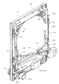
一方、図8は、内枠12に遊技盤30を組み付けた状態でその構成を示す背面図である。また、図9は内枠12を後方より見た斜視図である。ここでは図8及び図9を用いて内枠12及び遊技盤30の裏面構成を説明する。   On the other hand, FIG. 8 is a rear view showing the configuration of the game board 30 assembled to the inner frame 12. FIG. 9 is a perspective view of the inner frame 12 as viewed from the rear. Here, the back side structure of the inner frame 12 and the game board 30 will be described with reference to FIGS. 8 and 9.

遊技盤30は、樹脂ベース20に囲まれた四角枠状の設置領域に設置され、内枠12に設けられた複数(本実施形態では4カ所)の係止固定具211,212によって脱落しないように固定されている。係止固定具211,212は手動で回動でき、固定位置(ロック位置)と固定解除位置(アンロック位置)とを切り替えることができるよう構成されており、図8にはロック状態を示す。遊技盤30の左右3カ所の係止固定具211は金属片を折り曲げ形成したL型の金具であり、遊技盤30の固定状態で内枠12外方へ張り出さないよう構成されている。なお、遊技盤30の下部1カ所の係止固定具212は樹脂製のI型の留め具である。   The game board 30 is installed in a rectangular frame-shaped installation area surrounded by the resin base 20 so as not to drop off by a plurality of (four in this embodiment) locking fixtures 211 and 212 provided on the inner frame 12. It is fixed to. The locking fixtures 211 and 212 can be manually rotated to switch between a fixed position (lock position) and a fixed release position (unlock position). FIG. 8 shows a locked state. The locking fixtures 211 at the three left and right sides of the game board 30 are L-shaped metal fittings formed by bending metal pieces, and are configured not to protrude outwardly from the inner frame 12 when the game board 30 is fixed. Note that the locking fixture 212 at one lower portion of the game board 30 is an I-shaped fastener made of resin.

遊技盤30の中央には可変表示装置ユニット35が配置されている。可変表示装置ユニット35においては、センターフレーム47(図3参照)を背後から覆う樹脂製(例えばABS製)のフレームカバー213が後方に突出して設けられており、そのフレームカバー213の後端に、液晶表示装置たる第1図柄表示装置42と表示制御装置45とが前後に重ねられた状態で着脱可能に取り付けられている。フレームカバー213内には、センターフレーム47に内蔵されたLED等を駆動するためのLED制御基板などが配設されている。   A variable display device unit 35 is disposed in the center of the game board 30. In the variable display device unit 35, a frame cover 213 made of resin (for example, made of ABS) that covers the center frame 47 (see FIG. 3) from behind is provided to protrude rearward, and at the rear end of the frame cover 213, The 1st symbol display apparatus 42 and the display control apparatus 45 which are liquid crystal display devices are attached so that attachment or detachment is possible in the state piled up back and forth. In the frame cover 213, an LED control board for driving LEDs and the like built in the center frame 47 are disposed.

また、遊技盤30の裏面には、可変表示装置ユニット35を取り囲むようにして裏枠セット215が取り付けられている。この裏枠セット215は、遊技盤30の裏面に張り付くようにして設けられる薄型の樹脂成形品(例えばABS製)であって、各種入賞口に入賞した遊技球を回収するための遊技球回収機構が形成されている。詳しくは、裏枠セット215の下方には、前述した一般入賞口31、可変入賞装置32、第1契機対応口33(それぞれ図3参照)の遊技盤開口部に対応し、且つ下流側で1カ所に集合する回収通路216が形成されている。また、遊技盤30の下方には、内枠12にやはり樹脂製(例えばポリカーボネイト樹脂製)の排出通路盤217が取り付けられており、該排出通路盤217には、排出球をパチンコ機10外部へ案内するための排出通路218が形成されている。従って、図8に仮想線で例示するように、一般入賞口31等に入賞した遊技球は何れも裏枠セット215の回収通路216を介して集合し、さらに排出通路盤217の排出通路218を介してパチンコ機10外部に排出される。なお、アウト口36(図3参照)も同様に排出通路218に通じており、何れの入賞口にも入賞しなかった遊技球も排出通路218を介してパチンコ機10外部に排出される。   A back frame set 215 is attached to the back surface of the game board 30 so as to surround the variable display device unit 35. The back frame set 215 is a thin resin-molded product (for example, made of ABS) provided so as to stick to the back surface of the game board 30, and a game ball collecting mechanism for collecting game balls won in various winning openings. Is formed. Specifically, below the back frame set 215, corresponding to the game board opening of the above-described general winning opening 31, variable winning apparatus 32, first opportunity corresponding opening 33 (see FIG. 3 respectively) and 1 on the downstream side. A collection passage 216 that collects at a place is formed. In addition, a discharge passage board 217 made of resin (for example, made of polycarbonate resin) is also attached to the inner frame 12 below the game board 30, and discharge balls are sent to the outside of the pachinko machine 10 in the discharge passage board 217. A discharge passage 218 for guiding is formed. Therefore, as illustrated in phantom lines in FIG. 8, all the game balls won in the general winning opening 31 etc. gather through the collection passage 216 of the back frame set 215, and further the discharge passage 218 of the discharge passage board 217. Through the pachinko machine 10. In addition, the out port 36 (see FIG. 3) similarly communicates with the discharge passage 218, and the game balls that have not won any prize opening are discharged to the outside of the pachinko machine 10 through the discharge passage 218.

上記構成では、遊技盤30の下端面を境界にして、上方に裏枠セット215(回収通路216)が、下方に排出通路盤217(排出通路218)が設けられており、排出通路盤217が遊技盤30に対して前後方向に重複(オーバーラップ)せずに設けられている。従って、遊技盤30を内枠12から取り外す際において、排出通路盤17が遊技盤取り外しの妨げになるといった不都合が生じることもない。   In the above configuration, with the lower end surface of the game board 30 as a boundary, a back frame set 215 (collection passage 216) is provided above, and a discharge passage board 217 (discharge passage 218) is provided below. The game board 30 is provided without overlapping (overlapping) in the front-rear direction. Therefore, when removing the game board 30 from the inner frame 12, there is no inconvenience that the discharge passage board 17 prevents the game board from being removed.

なお、排出通路盤217は、パチンコ機前面の上皿19の丁度裏側辺りに設けられており、上皿19に至る球排出口(図2の球通路樋69)より針金等を差し込み、さらにその針金等を内枠12と排出通路盤217との隙間を通じて遊技領域側に侵入させるといった不正行為が考えられる。そこで本パチンコ機10では、排出通路盤217の上皿19の丁度裏側辺りに、内枠12にほぼ一体的に重なり合うようにしてパチンコ機前方に延びるプレート219が設けられている。従って、内枠12と排出通路盤217との隙間から針金等を侵入させようとしてもそれがプレート219にて阻害され、遊技領域にまで針金等を侵入させることが非常に困難となる。結果として、針金等を利用して可変入賞装置32(大入賞口)を強制的に開放する等の不正行為を防止することができる。   The discharge passage board 217 is provided just behind the upper plate 19 on the front surface of the pachinko machine. A wire or the like is inserted from a ball discharge port (ball passage rod 69 in FIG. 2) leading to the upper plate 19, An illegal act of causing a wire or the like to enter the game area side through a gap between the inner frame 12 and the discharge passage board 217 can be considered. Accordingly, in the pachinko machine 10, a plate 219 extending in front of the pachinko machine so as to overlap the inner frame 12 almost integrally is provided just behind the upper plate 19 of the discharge passage board 217. Therefore, even if a wire or the like tries to enter from the gap between the inner frame 12 and the discharge passage board 217, the wire or the like is obstructed by the plate 219, and it becomes very difficult to make the wire or the like enter the game area. As a result, it is possible to prevent an illegal act such as forcibly opening the variable winning device 32 (large winning opening) using a wire or the like.

また、遊技盤30の裏面には、各種入賞口などの遊技球の通過を検出するための入球検出手段としての入賞感知機構などが設けられている。具体的には、遊技盤30表側の一般入賞口31に対応する位置には入賞口スイッチ221が設けられ、可変入賞装置32には、特定領域スイッチ222とカウントスイッチ223とが設けられている。特定領域スイッチ222は、大当たり状態で可変入賞装置32に入賞した遊技球が特定領域(大当たり状態継続を判定するための領域)に入ったことを判定するスイッチであり、カウントスイッチ223は入賞球をカウントするスイッチである。また、第1契機対応口33に対応する位置には特定入球検出手段としての第1契機対応口(始動口)スイッチ224が設けられ、第2契機対応口34に対応する位置には第2契機対応口(ゲート)スイッチ225が設けられている。これら各スイッチ221〜225は入球検出手段として機能しうる。   Further, on the back surface of the game board 30, a winning detection mechanism as a winning detection means for detecting the passage of gaming balls such as various winning openings is provided. Specifically, a prize opening switch 221 is provided at a position corresponding to the general prize opening 31 on the front side of the game board 30, and a specific area switch 222 and a count switch 223 are provided in the variable prize winning device 32. The specific area switch 222 is a switch for determining that a game ball won in the variable winning device 32 in the big hit state has entered a specific area (an area for determining whether or not to continue the big hit state), and the count switch 223 displays the winning ball. It is a switch to count. In addition, a first opportunity corresponding port (starting port) switch 224 is provided as a specific entrance detection means at a position corresponding to the first opportunity corresponding port 33, and a second corresponding to the second opportunity corresponding port 34 is a second. An opportunity corresponding port (gate) switch 225 is provided. Each of these switches 221 to 225 can function as a ball entry detecting means.

入賞口スイッチ221及び第2契機対応口(ゲート)スイッチ225は、後述する電気配線(ケーブルコネクタ)を介して盤面中継基板226に接続され、さらにこの盤面中継基板226が後述する主基板(主制御装置261)に電気配線を介して接続されている。また、特定領域スイッチ222及びカウントスイッチ223は電気配線を介して大入賞口中継基板227に接続され、さらにこの大入賞口中継基板227がやはり電気配線を介して主基板に接続されている。これに対し、第1契機対応口(始動口)スイッチ224は中継基板を経ることなく直接主基板に電気配線を介して接続されている。これらの詳細については後述する。   The prize opening switch 221 and the second opportunity corresponding gate (gate) switch 225 are connected to the board relay board 226 via electric wiring (cable connector) described later, and the board relay board 226 is further connected to a main board (main control) described later. Connected to the device 261) via electrical wiring. In addition, the specific area switch 222 and the count switch 223 are connected to the big prize opening relay board 227 via electric wiring, and this big winning opening relay board 227 is also connected to the main board via electric wiring. On the other hand, the first opportunity corresponding port (starting port) switch 224 is directly connected to the main board via the electric wiring without passing through the relay board. Details of these will be described later.

その他図示は省略するが、可変入賞装置32には、大入賞口を開放するための大入賞口ソレノイドと、入賞球を特定領域に導くための入賞球振分板ソレノイドが設けられ、第1契機対応口33には、電動役物を開放するための第1契機対応口(始動口)ソレノイドが設けられている。なお、図8,9において符号228は打球槌等を備えるセットハンドルであり、符号229は発射モータである。   Although not shown in the drawings, the variable winning device 32 is provided with a large winning opening solenoid for opening the large winning opening and a winning ball distribution plate solenoid for guiding the winning ball to a specific area. The corresponding port 33 is provided with a first opportunity corresponding port (starting port) solenoid for opening the electric accessory. In FIGS. 8 and 9, reference numeral 228 denotes a set handle including a hitting ball and the like, and reference numeral 229 denotes a firing motor.

上記入賞感知機構にて各々検出された検出結果は、後述する主基板に取り込まれ、該主基板よりその都度の入賞状況に応じた払出指令(遊技球の払出個数)が払出制御基板に送信される。そして、該払出制御基板の出力により所定数の遊技球の払出が実施される。かかる場合、各種入賞口に入賞した遊技球を入賞球処理装置に一旦集め、その入賞球処理装置で入賞球の存在を1つずつ順番に確認した上で払出を行う従来方式(いわゆる証拠球方式)とは異なり、本実施形態のパチンコ機10では、各種入賞口毎に遊技球の入賞を電気的に感知して払出が直ちに行われる(すなわち、本パチンコ機10では入賞球処理装置を廃止している)。故に、払い出す遊技球が多量にあっても、その払出をいち早く実施することが可能となる。   The detection results detected by the winning detection mechanism are taken into the main board, which will be described later, and a payout command (the number of game balls to be paid out) corresponding to the winning situation is sent from the main board to the payout control board. The Then, a predetermined number of game balls are paid out by the output of the payout control board. In such a case, a conventional method (so-called evidence ball method) in which game balls won in various winning openings are once collected in a winning ball processing device and paid out after the winning ball processing device confirms the presence of winning balls one by one in order. In the pachinko machine 10 according to the present embodiment, the game ball winning is electrically detected for each winning opening and the payout is immediately made (that is, the pachinko machine 10 eliminates the winning ball processing device). ing). Therefore, even if there are a lot of game balls to be paid out, the payout can be carried out quickly.

また、裏枠セット215には、第1制御基板ユニット201を取り付けるための取付機構が設けられている。具体的には、この取付機構として、遊技盤30の裏面から見て左下隅部には上下方向に延びる支持金具231が設けられ、この支持金具231には同一軸線上に上下一対の支持孔が形成されている。その他、遊技盤30の右下部において符号232は上下一対の被締結孔(ナイラッチ孔)であり、同左上部において符号233は係止爪片である。   The back frame set 215 is provided with an attachment mechanism for attaching the first control board unit 201. Specifically, as this attachment mechanism, a support bracket 231 extending in the vertical direction is provided at the lower left corner when viewed from the back of the game board 30, and the support bracket 231 has a pair of upper and lower support holes on the same axis. Is formed. In addition, in the lower right part of the game board 30, reference numeral 232 is a pair of upper and lower fastening holes (ny latch holes), and in the upper left part, reference numeral 233 is a locking claw piece.

また、内枠12の裏面には、第2制御基板ユニット202や裏パックユニット203を取り付けるための取付機構が設けられている。具体的には、内枠12にはその右端部に長尺状の支持金具235が取り付けられており、その構成を図10に示す。図10に示すように、支持金具235は長尺板状の金具本体236を有し、その金具本体236より起立させるようにして、下方2カ所に第2制御基板ユニット用の支持孔部237が形成されると共に、上方2カ所に裏パックユニット用の支持孔部238が形成されている。それら支持孔部237,238にはそれぞれ同軸の支持孔が形成されている。その他、図8,9に示すように、第2制御基板ユニット用の取付機構として、内枠12には、遊技盤設置領域よりも下方左端部に上下一対の被締結孔(ナイラッチ孔)239が設けられている。また、裏パックユニット用の取付機構として、内枠12には、遊技盤設置領域の左端部に上下一対の被締結孔(ナイラッチ孔)240が設けられている。但し、第2制御基板ユニット用の支持金具と裏パックユニット用の支持金具とを各々個別の部材で設けることも可能である。符号241,242,243は、遊技盤30との間に裏パックユニット203を挟み込んで支持するための回動式の固定具である。   An attachment mechanism for attaching the second control board unit 202 and the back pack unit 203 is provided on the back surface of the inner frame 12. Specifically, a long support fitting 235 is attached to the inner frame 12 at its right end, and its configuration is shown in FIG. As shown in FIG. 10, the support metal fitting 235 has a long plate-like metal fitting main body 236, and the support hole 237 for the second control board unit is formed at two lower positions so as to stand up from the metal fitting main body 236. At the same time, support hole portions 238 for the back pack unit are formed at two upper positions. Coaxial support holes are formed in the support hole portions 237 and 238, respectively. In addition, as shown in FIGS. 8 and 9, as an attachment mechanism for the second control board unit, the inner frame 12 has a pair of upper and lower fastening holes (nai latch holes) 239 at the lower left end portion from the game board installation area. Is provided. As a mounting mechanism for the back pack unit, the inner frame 12 is provided with a pair of upper and lower fastening holes (nylatching holes) 240 at the left end of the game board installation area. However, the support bracket for the second control board unit and the support bracket for the back pack unit can be provided as separate members. Reference numerals 241, 242, and 243 denote rotational fixtures for sandwiching and supporting the back pack unit 203 with the game board 30.

その他、内枠12の背面構成において、遊技盤30の右下部には、後述する払出機構より払い出される遊技球を上皿19、下皿15、又は排出通路218の何れかに振り分けるための遊技球分配部245が設けられている。すなわち、遊技球分配部245の開口部245aは上皿19に通じ、開口部245bは下皿15に通じ、開口部245cは排出通路218に通じる構成となっている(図9参照)。なお、従来、遊技球分配部245に相当する部分が裏パックユニット203側に設けられていたため、上皿19に至る球排出口(図2の球通路樋69)を通じて裏パックユニット203を押すことにより、内枠12と遊技球分配部245に相当する部分との間に隙間が生じ、その隙間を通じて針金等を差し込み、内部機器を操作するといった不正行為が考えられた。そこで本パチンコ機10では、遊技球分配部245として内枠12側に設け、なおかつ固定手段によって固定することにより、そのような不正行為を防止している。さらに、遊技球分配部245の上端面は遊技盤30の下端面が設置される高さ位置に合わせて形成されており、遊技盤30の取外しの妨げとならないように工夫されている。   In addition, in the rear configuration of the inner frame 12, a game ball for distributing a game ball paid out from a payout mechanism described later to any of the upper plate 19, the lower plate 15, or the discharge passage 218 is provided at the lower right portion of the game board 30. A distribution unit 245 is provided. That is, the opening 245a of the game ball distributing unit 245 communicates with the upper plate 19, the opening 245b communicates with the lower plate 15, and the opening 245c communicates with the discharge passage 218 (see FIG. 9). Conventionally, since a portion corresponding to the game ball distributing unit 245 is provided on the back pack unit 203 side, the back pack unit 203 is pushed through the ball discharge port (ball passage wall 69 in FIG. 2) reaching the upper plate 19. As a result, a gap is formed between the inner frame 12 and a portion corresponding to the game ball distributing unit 245, and an illegal act of inserting a wire or the like through the gap and operating the internal device has been considered. Therefore, in the pachinko machine 10, such illegal acts are prevented by providing the game ball distribution unit 245 on the inner frame 12 side and fixing the game ball distribution unit 245 by a fixing means. Further, the upper end surface of the game ball distributing unit 245 is formed in accordance with the height position where the lower end surface of the game board 30 is installed, and is devised so as not to prevent the game board 30 from being removed.

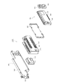
次に、第1制御基板ユニット201を図11〜図14を用いて説明する。図11は第1制御基板ユニット201の正面図、図12は同ユニット201の斜視図、図13は同ユニット201の分解斜視図、図14は同ユニット201を裏面から見た分解斜視図である。   Next, the first control board unit 201 will be described with reference to FIGS. 11 is a front view of the first control board unit 201, FIG. 12 is a perspective view of the unit 201, FIG. 13 is an exploded perspective view of the unit 201, and FIG. 14 is an exploded perspective view of the unit 201 viewed from the back. .

第1制御基板ユニット201は略L字状をなす取付台251を有し、この取付台251に制御装置としての主制御装置261と音声ランプ制御装置262とが搭載されている。ここで、主制御装置261は、主たる制御を司るCPU、遊技プログラムを記憶したROM、遊技の進行に応じた必要なデータを記憶するRAM、各種機器との連絡をとるポート、各種抽選の際に用いられる乱数発生器、時間計数や同期を図る場合などに使用されるクロックパルス発生回路等を含む主基板を具備しており、この主基板が透明樹脂材料等よりなる基板ボックス263に収容されて構成されている。なお、基板ボックス263は、略直方体形状のボックスベースと該ボックスベースの開口部を覆うボックスカバーとを備えている。これらボックスベースとボックスカバーとは封印ユニット264(封印手段)によって開封不能に連結され、これにより基板ボックス263が封印されている。   The first control board unit 201 has a mounting base 251 having a substantially L shape, and a main control device 261 and an audio lamp control device 262 as control devices are mounted on the mounting base 251. Here, the main control device 261 includes a CPU that controls the main control, a ROM that stores a game program, a RAM that stores necessary data according to the progress of the game, a port that communicates with various devices, and various lotteries. It has a main board including a random number generator used, a clock pulse generation circuit used for time counting and synchronization, and the main board is accommodated in a board box 263 made of a transparent resin material or the like. It is configured. The substrate box 263 includes a substantially rectangular parallelepiped box base and a box cover that covers the opening of the box base. The box base and the box cover are connected to each other by a sealing unit 264 (sealing means) so that the box box 263 is sealed.

封印手段としての封印ユニット264はボックスベースとボックスカバーとを開封不能に連結する構成であれば任意の構成が適用できるが、ここでは図11等に示すように、5つの封印部材が連結された構成となっており、この封印部材の長孔に係止爪を挿入することでボックスベースとボックスカバーとが開封不能に連結されるようになっている。封印ユニット264による封印処理は、その封印後の不正な開封を防止し、また万一不正開封が行われてもそのような事態を早期に且つ容易に発見可能とするものであって、一旦開封した後でも再度開封・封印処理を行うこと自体は可能である。すなわち、封印ユニット264を構成する5つの封印部材のうち、少なくとも一つの封印部材の長孔に係止爪を挿入することにより封印処理が行われる。そして、収容した主基板の不具合などにより基板ボックス263を開封する場合には、係止爪が挿入された封印部材と他の封印部材との連結を切断する。その後、再度封印処理する場合は他の封印部材の長孔に係止爪を挿入する。基板ボックス263の開封を行った旨の履歴を当該基板ボックス263に残しておけば、基板ボックス263を見ることで不正な開封が行われた旨を容易に発見できる。   As the sealing unit 264 as the sealing means, any configuration can be applied as long as the box base and the box cover are connected so as not to be opened, but here, as shown in FIG. 11 and the like, five sealing members are connected. The box base and the box cover are connected so that they cannot be opened by inserting a locking claw into the long hole of the sealing member. The sealing process by the sealing unit 264 prevents unauthorized opening after the sealing, and makes it possible to detect such a situation early and easily even if the unauthorized opening is performed. It is possible to perform the opening / sealing process again even after the operation. That is, the sealing process is performed by inserting the locking claw into the long hole of at least one sealing member among the five sealing members constituting the sealing unit 264. And when opening the board | substrate box 263 by the malfunction of the accommodated main board | substrate etc., the connection of the sealing member in which the latching claw was inserted, and another sealing member is cut | disconnected. Thereafter, when the sealing process is performed again, the locking claws are inserted into the long holes of the other sealing members. If the history of opening the board box 263 is left in the board box 263, it can be easily found that the illegal opening has been performed by looking at the board box 263.

但し、主基板には、上記各ケーブルコネクタのコネクタを接続するための端子部が設けられており、該端子部は、基板ボックス263から露出状態となっている。かかる端子部の露出は、他の基板及び基板ボックスについても同様である。   However, the main board is provided with terminal portions for connecting the connectors of the cable connectors, and the terminal portions are exposed from the board box 263. The exposure of the terminal portion is the same for other substrates and substrate boxes.

また、音声ランプ制御装置262は、例えば主制御装置261(主基板)又は表示制御装置45からの指示に従い音声やランプ表示の制御を司るCPUや、その他ROM、RAM、各種ポート等を含む音声ランプ制御基板を具備しており、この音声ランプ制御基板が透明樹脂材料等よりなる基板ボックス265に収容されて構成されている。音声ランプ制御装置262上には電源中継基板266が搭載されており、後述する電源基板より供給される電源がこの電源中継基板266を介して表示制御装置45及び音声ランプ制御装置262に出力されるようになっている。   The voice lamp control device 262 is a voice lamp including, for example, a CPU that controls voice and lamp display in accordance with instructions from the main control device 261 (main board) or the display control device 45, and other ROM, RAM, various ports, and the like. The audio lamp control board is housed in a board box 265 made of a transparent resin material or the like. A power relay board 266 is mounted on the sound lamp control device 262, and power supplied from a power board described later is output to the display control device 45 and the sound lamp control device 262 via the power relay board 266. It is like that.

取付台251は、有色(例えば緑、青等)の樹脂材料(例えばポリカーボネイト樹脂製)にて成形され、その表面に平坦状をなす2つの基板搭載面252,253が設けられている。これら基板搭載面252,253は直交する向きに延び、前後方向に段差をもって形成されている。但し、取付台251は無色透明又は半透明の樹脂成形品であっても良い。   The mounting base 251 is formed of a colored (for example, green, blue, etc.) resin material (for example, made of polycarbonate resin), and has two substrate mounting surfaces 252 and 253 that are flat on the surface. These substrate mounting surfaces 252 and 253 extend in a direction orthogonal to each other, and are formed with a step in the front-rear direction. However, the mounting base 251 may be a colorless transparent or translucent resin molded product.

そして、一方の基板搭載面252上に主制御装置261(主基板)が横長の向きに配置されると共に、他方の基板搭載面253上に音声ランプ制御装置262(音声ランプ制御基板)が縦長の向きに配置されるようになっている。特に、主制御装置261は、パチンコ機10裏面から見て手前側に配置され、音声ランプ制御装置262はその奥側に配置される。この場合、基板搭載面252,253が前後方向に段差をもって形成されているため、これら基板搭載面252,253に主制御装置261及び音声ランプ制御装置262を搭載した状態において各制御装置261,262はその一部を前後に重ねて配置されるようになる。つまり、図12等にも見られるように、主制御装置261はその一部(本実施形態では1/3程度)が浮いた状態で配置されるようになる。故に、主制御装置261に重なる領域まで音声ランプ制御装置262を拡張することが可能となり、当該制御基板の大型化にも良好に対処できる。また、各制御装置が効率良く設置できるようになる。また、第1制御基板ユニット201を遊技盤30に装着した状態では、基板搭載面252の後方にスペースが確保され、可変入賞装置32やその電気配線等が無理なく設置できるようになっている。   The main control device 261 (main substrate) is arranged in a landscape orientation on one board mounting surface 252 and the audio lamp control device 262 (audio lamp control board) is arranged in a portrait orientation on the other substrate mounting surface 253. It is arranged in the direction. In particular, the main control device 261 is disposed on the near side as viewed from the back of the pachinko machine 10, and the sound lamp control device 262 is disposed on the back side. In this case, since the substrate mounting surfaces 252 and 253 are formed with steps in the front-rear direction, the control devices 261 and 262 are mounted with the main controller 261 and the sound lamp controller 262 mounted on the substrate mounting surfaces 252 and 253. Are arranged with a part of them stacked one after another. That is, as can be seen in FIG. 12 and the like, the main controller 261 is arranged in a state where a part thereof (about 1/3 in this embodiment) is floated. Therefore, the sound lamp control device 262 can be expanded to an area overlapping with the main control device 261, and the enlargement of the control board can be dealt with satisfactorily. Also, each control device can be installed efficiently. Further, when the first control board unit 201 is mounted on the game board 30, a space is secured behind the board mounting surface 252 so that the variable winning device 32 and its electric wiring can be installed without difficulty.

図13及び図14に示すように、主基板用の基板搭載面252には、左右2カ所に横長形状の貫通孔254が形成されている。これに対応して、主制御装置261の基板ボックス263には、その裏面の左右2カ所に回動式の固定具267が設けられている。主制御装置261を基板搭載面252に搭載する際には、基板搭載面252の貫通孔254に固定具267が通され、その状態で固定具267が回動されて主制御装置261がロックされる。従って、上述の通り主制御装置261はその一部が浮いた状態で配置されるとしても、当該主制御装置261の脱落等の不都合が回避できる。また、主制御装置261は第1制御基板ユニット201(基板搭載面252)の裏面側から固定具267をロック解除しなければ、取り外しできないため、基板取り外し等の不正行為に対して抑止効果が期待できる。主基板用の基板搭載面252にはその裏面に格子状のリブ255が設けられている。   As shown in FIGS. 13 and 14, a horizontally long through hole 254 is formed in two places on the left and right of the board mounting surface 252 for the main board. Correspondingly, the substrate box 263 of the main control device 261 is provided with rotational fixing tools 267 at two places on the left and right sides of the back surface thereof. When the main controller 261 is mounted on the board mounting surface 252, the fixing tool 267 is passed through the through hole 254 of the board mounting surface 252, and the fixing tool 267 is rotated in this state to lock the main control apparatus 261. The Therefore, even if the main control device 261 is arranged in a state where it floats as described above, inconveniences such as dropping off of the main control device 261 can be avoided. In addition, since the main control device 261 cannot be removed unless the fixture 267 is unlocked from the back side of the first control board unit 201 (board mounting surface 252), it is expected to have a deterrent effect against illegal acts such as board removal. it can. A grid-like rib 255 is provided on the back surface of the substrate mounting surface 252 for the main substrate.

取付台251には、図11等の左端面に上下一対の支軸256が設けられており、この支軸256を図9等に示す支持金具231に取り付けることで、第1制御基板ユニット201が遊技盤30に対して開閉可能に支持される。また、取付台251には、右端部に締結具として上下一対のナイラッチ257が設けられると共に上端部に長孔258が設けられており、ナイラッチ257を図8等に示す被締結孔232にはめ込むと共に、長孔258に図8等に示す係止爪片233を係止させることで、第1制御基板ユニット201が遊技盤30に固定されるようになる。なお、支持金具231及び支軸256が前記図7の支軸部M1に、被締結孔232及びナイラッチ257が締結部M2に、係止爪片233及び長孔258が係止爪部M3に、それぞれ相当する。   The mounting base 251 is provided with a pair of upper and lower support shafts 256 on the left end surface of FIG. 11 and the like. The game board 30 is supported so that it can be opened and closed. Further, the mounting base 251 is provided with a pair of upper and lower nai latches 257 as fasteners at the right end portion and a long hole 258 at the upper end portion, and the nai latch 257 is fitted into the fastening hole 232 shown in FIG. The first control board unit 201 is fixed to the game board 30 by locking the locking claw pieces 233 shown in FIG. The support fitting 231 and the support shaft 256 are in the support shaft portion M1 of FIG. 7, the fastening hole 232 and the ny latch 257 are in the fastening portion M2, the locking claw piece 233 and the long hole 258 are in the locking claw portion M3, Each corresponds.

次に、第2制御基板ユニット202を図15〜図17を用いて説明する。図15は第2制御基板ユニット202の正面図、図16は同ユニット202の斜視図、図17は同ユニット202の分解斜視図である。   Next, the second control board unit 202 will be described with reference to FIGS. 15 is a front view of the second control board unit 202, FIG. 16 is a perspective view of the unit 202, and FIG. 17 is an exploded perspective view of the unit 202.

第2制御基板ユニット202は横長形状をなす取付台301を有し、この取付台301に払出制御装置311、発射制御装置312、電源装置313及びカードユニット接続基板314が搭載されている。払出制御装置311、発射制御装置312及び電源装置313は周知の通り制御の中枢をなすCPUや、その他ROM、RAM、各種ポート等を含む制御基板を具備しており、払出制御装置311の払出制御基板により、賞品球や貸出球の払出が制御される。また、発射制御装置312の発射制御基板により、遊技者によるハンドル18の操作に従い発射モータ229の制御が行われ、電源装置313の電源基板により、各種制御装置等で要する所定の電源電圧が生成され出力される。カードユニット接続基板314は、パチンコ機前面の貸球操作部120及び図示しないカードユニットに電気的に接続され、遊技者による球貸し操作の指令を取り込んでそれを払出制御装置311に出力するものである。なお、カードユニットを介さずに球貸し装置等から上皿に遊技球が直接貸し出される現金機では、カードユニット接続基板314を省略することも可能である。   The second control board unit 202 has a horizontally long mounting base 301 on which a payout control device 311, a firing control device 312, a power supply device 313 and a card unit connection board 314 are mounted. The payout control device 311, the launch control device 312, and the power supply device 313 are equipped with a control board including a central control CPU, ROM, RAM, various ports and the like as is well known. The payout of prize balls and rental balls is controlled by the substrate. The launch control board of the launch control apparatus 312 controls the launch motor 229 in accordance with the player's operation of the handle 18, and the power supply board of the power supply apparatus 313 generates a predetermined power supply voltage required by various control apparatuses. Is output. The card unit connection board 314 is electrically connected to the ball lending operation unit 120 on the front surface of the pachinko machine and a card unit (not shown), and receives a ball lending operation command by the player and outputs it to the payout control device 311. is there. Note that the card unit connection board 314 can be omitted in a cash machine in which game balls are lent directly to the upper plate from a ball lending device or the like without using a card unit.

上記払出制御装置311、発射制御装置312、電源装置313及びカードユニット接続基板314は、透明樹脂材料等よりなる基板ボックス315,316,317,318にそれぞれ収容されて構成されている。特に、払出制御装置311では、前述した主制御装置261と同様、基板ボックス315を構成するボックスベースとボックスカバーとが封印ユニット319(封印手段)によって開封不能に連結され、これにより基板ボックス315が封印されている。   The payout control device 311, the firing control device 312, the power supply device 313, and the card unit connection substrate 314 are respectively configured to be accommodated in substrate boxes 315, 316, 317, and 318 made of a transparent resin material or the like. In particular, in the dispensing control device 311, similarly to the main control device 261 described above, the box base and the box cover constituting the substrate box 315 are connected to each other by the sealing unit 319 (sealing means) so that the substrate box 315 is not opened. Sealed.

払出制御装置311には状態復帰スイッチ321が設けられている。例えば、払出モータ部の球詰まり等、払出エラーの発生時において状態復帰スイッチ321が押下されると、払出モータが正逆回転され、球詰まりの解消(正常状態への復帰)が図られるようになっている。   The payout control device 311 is provided with a state return switch 321. For example, when the state return switch 321 is pressed when a payout error occurs, such as a ball jam in the payout motor unit, the payout motor is rotated forward and reverse so that the ball jam is eliminated (return to the normal state). It has become.

また、電源装置313にはRAM消去スイッチ323が設けられている。本パチンコ機10はバックアップ機能を有しており、万一停電が発生した際でも停電時の状態を保持し、停電からの復帰(復電)の際には停電時の状態に復帰できるようになっている。従って、通常手順で(例えばホールの営業終了時に)電源遮断すると電源遮断前の状態が記憶保持されることから、電源投入時に初期状態に戻したい場合には、RAM消去スイッチ323を押しながら電源を投入することとしている。   Further, the power supply device 313 is provided with a RAM erase switch 323. This pachinko machine 10 has a backup function, so that even if a power failure occurs, it maintains the state at the time of a power failure, and can be restored to the state at the time of a power failure when returning from a power failure (power recovery) It has become. Therefore, if the power is turned off in the normal procedure (for example, when the hall is closed), the state before the power is turned off is stored. If you want to return to the initial state when the power is turned on, turn on the power while holding down the RAM erase switch 323. We are going to throw it in.

取付台301は例えば無色透明な樹脂成形品よりなり、その表面に平坦状をなす基板搭載面302が設けられている。この場合、発射制御装置312、電源装置313及びカードユニット接続基板314は取付台301の基板搭載面302に横並びの状態で直接搭載され、電源装置313の基板ボックス317上に払出制御装置311が取付台303を介して搭載されている。   The mounting base 301 is made of, for example, a colorless and transparent resin molded product, and a flat substrate mounting surface 302 is provided on the surface thereof. In this case, the launch control device 312, the power supply device 313 and the card unit connection board 314 are directly mounted side by side on the board mounting surface 302 of the mounting base 301, and the payout control apparatus 311 is mounted on the board box 317 of the power supply apparatus 313. It is mounted via a table 303.

また、取付台301には、図15等の右端部に上下一対の支軸305が設けられており、この支軸305を図8等に示す支持孔部237に上方から挿通させることで、第2制御基板ユニット202が内枠12に対して開閉可能に支持される。また、取付台301には、左端部に締結具として上下一対のナイラッチ306が設けられており、ナイラッチ306を図8等に示す被締結孔239にはめ込むことで、第2制御基板ユニット202が内枠12に開閉不能に固定されるようになる。なお、支持孔部237及び支軸305が前記図7の支軸部M4に、被締結孔239及びナイラッチ306が締結部M5に、それぞれ相当する。   Further, the mounting base 301 is provided with a pair of upper and lower support shafts 305 at the right end in FIG. 15 and the like. By inserting these support shafts 305 into the support hole 237 shown in FIG. 2 The control board unit 202 is supported to be openable and closable with respect to the inner frame 12. Further, the mounting base 301 is provided with a pair of upper and lower nai latches 306 as fasteners at the left end portion. By fitting the nai latch 306 into the fastening hole 239 shown in FIG. It is fixed to the frame 12 so that it cannot be opened and closed. The support hole portion 237 and the support shaft 305 correspond to the support shaft portion M4 in FIG. 7, and the fastened hole 239 and the ny latch 306 correspond to the fastening portion M5, respectively.

次に、裏パックユニット203の構成を説明する。裏パックユニット203は、樹脂成形された裏パック351と遊技球の払出機構部352とを一体化したものであり、パチンコ機10の背面から見た背面図を図18に示し、分解斜視図を図19に示す。   Next, the configuration of the back pack unit 203 will be described. The back pack unit 203 is formed by integrating a back pack 351 made of resin and a payout mechanism portion 352 for a game ball. FIG. 18 is a rear view of the pachinko machine 10 viewed from the back, and FIG. It shows in FIG.

裏パック351は例えばABS樹脂により一体成形されており、略平坦状のベース部353と、パチンコ機後方に突出し横長の略直方体形状をなす保護カバー部354とを有する。保護カバー部354は左右側面及び上面が閉鎖され且つ下面のみが開放された形状をなし、少なくとも可変表示装置ユニット35を囲むのに十分な大きさを有する(但し本実施形態では、前述の音声ランプ制御装置262も合わせて囲む構成となっている)。保護カバー部354の背面には多数の通気孔354aが設けられている。この通気孔354aは各々が長孔状をなし、それぞれの通気孔354aが比較的近い位置で隣り合うよう設けられている。従って、隣り合う通気孔354a間にある樹脂部分を切断することにより、裏パック351の背面を容易に開口させることができる。つまり、通気孔354a間の樹脂部分を切断してその内部の表示制御装置45等を露出させることで、所定の検定等を容易に実施することができる。   The back pack 351 is integrally formed of, for example, ABS resin, and includes a substantially flat base portion 353 and a protective cover portion 354 that protrudes rearward from the pachinko machine and has a horizontally long substantially rectangular parallelepiped shape. The protective cover portion 354 has a shape in which the left and right side surfaces and the upper surface are closed and only the lower surface is opened, and has a size sufficient to surround at least the variable display device unit 35 (however, in the present embodiment, the sound lamp described above is used). The control device 262 is also enclosed. A large number of ventilation holes 354 a are provided on the back surface of the protective cover portion 354. Each of the air holes 354a has a long hole shape, and the air holes 354a are adjacent to each other at a relatively close position. Therefore, the back surface of the back pack 351 can be easily opened by cutting the resin portion between the adjacent vent holes 354a. That is, a predetermined test or the like can be easily performed by cutting the resin portion between the vent holes 354a to expose the display control device 45 and the like inside.

また、ベース部353には、保護カバー部354を迂回するようにして払出機構部352が配設されている。すなわち、裏パック351の最上部には上方に開口したタンク355が設けられており、このタンク355には遊技ホールの島設備から供給される遊技球が逐次補給される。タンク355の下方には、例えば横方向2列(2条)の球通路を有し下流側に向けて緩やかに傾斜するタンクレール356が連結され、さらにタンクレール356の下流側には縦向きにケースレール357が連結されている。払出装置358はケースレール357の最下流部に設けられ、払出モータ358a等の所定の電気的構成により必要個数の遊技球の払出が適宜行われる。そして、払出装置358より払い出された遊技球は図19に示す払出通路359等を通じて前記上皿19に供給される。   In addition, a payout mechanism 352 is disposed on the base 353 so as to bypass the protective cover 354. That is, a tank 355 opened upward is provided at the uppermost portion of the back pack 351, and game balls supplied from the island facilities of the game hall are sequentially supplied to the tank 355. Below the tank 355, for example, a tank rail 356 that has two rows (two rows) of ball passages in the horizontal direction and that is gently inclined toward the downstream side is connected. Further, the tank rail 356 is arranged vertically on the downstream side of the tank rail 356. A case rail 357 is connected. The payout device 358 is provided in the most downstream portion of the case rail 357, and a required number of game balls are paid out appropriately according to a predetermined electrical configuration such as a payout motor 358a. The game balls paid out from the payout device 358 are supplied to the upper plate 19 through the payout passage 359 and the like shown in FIG.

タンクレール356には、当該タンクレール356に振動を付加するためのバイブレータ360が取り付けられている。従って、仮にタンクレール356付近で球詰まりが生じた際、バイブレータ360が駆動されることで球詰まりが解消されるようになっている。なお、バイブレータ360は、パチンコ機の設計変更等による位置変更や故障時等における交換が容易になるよう、モータ等の振動体が本体部であるケース内に収容されたバイブレータ・ユニットとして構成されており、当該ユニットが着脱可能なようにタンクレール356に取付けられている。なお、前記バイブレータ・ユニットは、その本体部(ケース面)がタンクレール356に密着せず、本体部から突出した足部(振動伝達子)を介してタンクレール356の側面に取付けられており、そのバイブ振動がより効果的にタンクレール356に伝達されるよう構成されている。   A vibrator 360 for attaching vibration to the tank rail 356 is attached to the tank rail 356. Therefore, if a clogged ball occurs near the tank rail 356, the clogged ball is eliminated by driving the vibrator 360. The vibrator 360 is configured as a vibrator unit in which a vibrating body such as a motor is accommodated in a case which is a main body part so that a position change due to a design change or the like of a pachinko machine can be easily replaced in the case of a failure. The unit is attached to the tank rail 356 so as to be detachable. In addition, the vibrator unit is attached to the side surface of the tank rail 356 via a foot portion (vibration transmitter) protruding from the main body portion without the main body portion (case surface) being in close contact with the tank rail 356, The vibration is transmitted to the tank rail 356 more effectively.

タンクレール356の構成ついて詳述すると、図20に示すように、タンクレール356は上方に開口した長尺樋状をなすレール本体361を有し、レール本体361の始端部には球面状の球受部362が設けられている。この球受部362により、タンク355より落下してきた遊技球が円滑にレール本体361内に取り込まれる。また、レール本体361には長手方向に延びる仕切壁363が設けられており、この仕切壁363により遊技球が二手に分流されるようになっている。仕切壁363により仕切られた2条の球通路は遊技球の直径よりも僅かに幅広となっている。仕切壁363により仕切られた各球通路の底面には、1筋又は2筋の突条364が設けられると共に、その突条364の側方に開口部365が設けられている。   The configuration of the tank rail 356 will be described in detail. As shown in FIG. 20, the tank rail 356 has a rail body 361 having a long bowl shape opened upward, and a spherical ball is formed at the start end of the rail body 361. A receiving part 362 is provided. By this ball receiving portion 362, the game ball dropped from the tank 355 is smoothly taken into the rail body 361. Further, the rail body 361 is provided with a partition wall 363 extending in the longitudinal direction, and the game balls are divided into two hands by the partition wall 363. The two ball passages partitioned by the partition wall 363 are slightly wider than the diameter of the game ball. One or two ridges 364 are provided on the bottom surface of each spherical passage partitioned by the partition wall 363, and an opening 365 is provided on the side of the ridge 364.

また、レール本体361には、その下流側半分程度の天井部分を覆うようにして整流板367が配設されている。この整流板367は、下流側になるほどタンクレール356内の球通路高さを制限するよう弓なりに反った形状をしており、さらにその下面には長手方向に延びる凸部368が形成されている。これにより、タンクレール356内を流れる各遊技球は最終的には上下に積み重なることなく下流側に流出する。従って、タンクレール356に多量の遊技球群が流れ込んできても、遊技球の噛み込みが防止され、タンクレール356内における球詰まりが解消されるようになっている。なお、レール本体361が黒色の導電性ポリカーボネイト樹脂により成形されるのに対し、整流板367は透明のポリカーボネイト樹脂により成形されている。整流板367は着脱可能に設けられており、当該整流板367を取り外すことによりタンクレール356内のメンテナンスが容易に実施できるようになっている。   In addition, a rectifying plate 367 is disposed on the rail body 361 so as to cover the ceiling portion of the downstream half. The rectifying plate 367 has a bowed shape so as to limit the height of the ball passage in the tank rail 356 toward the downstream side, and a convex portion 368 extending in the longitudinal direction is formed on the lower surface thereof. . Thereby, each game ball flowing in the tank rail 356 finally flows out downstream without being stacked up and down. Therefore, even if a large group of game balls flow into the tank rail 356, the game balls are prevented from being bitten and the ball clogging in the tank rail 356 is eliminated. The rail body 361 is formed of black conductive polycarbonate resin, whereas the rectifying plate 367 is formed of transparent polycarbonate resin. The rectifying plate 367 is detachably provided. By removing the rectifying plate 367, maintenance in the tank rail 356 can be easily performed.

図18,19の説明に戻り、払出機構部352には、払出制御装置311から払出装置358への払出指令の信号を中継する払出中継基板381が設置されると共に、外部より主電源を取り込むための電源スイッチ基板382が設置されている。電源スイッチ基板382には、電圧変換器を介して例えば交流24Vの主電源が供給され、電源スイッチ382aの切替操作により電源ON又は電源OFFとされるようになっている。   Returning to the description of FIGS. 18 and 19, the payout mechanism unit 352 is provided with a payout relay board 381 that relays a payout command signal from the payout control device 311 to the payout device 358, and takes in the main power from outside. The power switch board 382 is installed. The power switch board 382 is supplied with, for example, AC 24V main power via a voltage converter, and is turned on or off by switching the power switch 382a.

タンク355から払出通路359に至るまでの払出機構部352は何れも導電性を有する樹脂材料(例えば導電性ポリカーボネイト樹脂)にて成形され、その一部にてアースされている。これにより、遊技球の帯電によるノイズの発生が抑制されるようになっている。   The discharge mechanism 352 from the tank 355 to the discharge passage 359 is formed of a conductive resin material (for example, conductive polycarbonate resin) and grounded at a part thereof. Thereby, generation | occurrence | production of the noise by charging of a game ball is suppressed.

また、裏パック351には、図18等の右端部に上下一対の支軸385が設けられており、この支軸385を図8等に示す支持孔部238に上方から挿通させることで、裏パックユニット203が内枠12に対して開閉可能に支持される。また、裏パック351には、左端部に締結具として上下一対のナイラッチ386が設けられると共に、上端部に係止孔387が設けられており、ナイラッチ386を図8等に示す被締結孔240にはめ込むと共に、係止孔387に図8等に示す固定具242を係止させることで、裏パックユニット203が内枠12に開閉不能に固定されるようになる。また、本実施形態では、多くの遊技球が貯留され比較的負荷のかかるタンク355の近傍の係止部M8として、回動式のI型の留め具が採用されている。このため、ナイラッチ等の固定具を用いた場合に比べてより確実に裏パックユニット203(タンク355)の係止を行うことができる。このとき、図8等に示す固定具241,243によっても裏パックユニット203が内枠12に固定される。なお、支持孔部238及び支軸385が前記図7の支軸部M6に、被締結孔240及びナイラッチ386が締結部M7に、固定具242及び係止孔387が係止部M8に、それぞれ相当する。また、固定具243が係止部M9に相当する(図7参照)。   Further, the back pack 351 is provided with a pair of upper and lower support shafts 385 at the right end in FIG. 18 and the like, and the support shaft 385 is inserted into the support hole 238 shown in FIG. The pack unit 203 is supported so as to be openable and closable with respect to the inner frame 12. Further, the back pack 351 is provided with a pair of upper and lower nai latches 386 as fasteners at the left end portion, and a locking hole 387 is provided at the upper end portion. The nai latch 386 is inserted into the tightened hole 240 shown in FIG. The back pack unit 203 is fixed to the inner frame 12 so that it cannot be opened and closed by engaging the fixing hole 387 shown in FIG. Further, in the present embodiment, a rotating I-type fastener is employed as the locking portion M8 in the vicinity of the tank 355 that stores a lot of game balls and is relatively loaded. For this reason, the back pack unit 203 (tank 355) can be more reliably locked as compared with the case where a fixture such as a ny latch is used. At this time, the back pack unit 203 is also fixed to the inner frame 12 by the fixtures 241 and 243 shown in FIG. The support hole 238 and the support shaft 385 are in the support shaft portion M6 of FIG. 7, the fastening hole 240 and the ny latch 386 are in the fastening portion M7, and the fixture 242 and the locking hole 387 are in the locking portion M8, respectively. Equivalent to. Further, the fixture 243 corresponds to the locking portion M9 (see FIG. 7).

また、裏パックユニット203のベース部353には、外部中継端子板230用の開口部391が設けられており、裏パックユニット203の固定された状態でも、外部中継端子板230の取外し及び操作が可能となっている。   Further, the base 353 of the back pack unit 203 is provided with an opening 391 for the external relay terminal plate 230, so that the external relay terminal plate 230 can be removed and operated even when the back pack unit 203 is fixed. It is possible.

なお、上述してきた構成により、主制御装置261(基板ボックス263)の取外しを行おうとした場合には、まず裏パックユニット203を開け(又は取外し)、次に第1制御基板ユニット201を開け(又は取外し)、そして、固定具267を解除操作するという複雑な過程をふむことにより、ようやく行うことができる。このため、主制御装置261(基板ボックス263)の取り外し等の不正行為に対して抑止効果が期待できるようになっている。   When the main controller 261 (substrate box 263) is to be removed with the above-described configuration, the back pack unit 203 is first opened (or removed), and then the first control substrate unit 201 is opened ( Or removal), and a complicated process of releasing the fixture 267 can be performed at last. For this reason, a deterrent effect can be expected against illegal acts such as removal of the main controller 261 (board box 263).

さて、図21は、本パチンコ機10の電気的構造を示したブロック図である。パチンコ機10の主制御装置261には、演算装置である1チップマイコンとしてのCPU501が搭載されている。CPU501には、該CPU501により実行される各種の制御プログラムや固定値データを記憶したROM502と、そのROM502内に記憶される制御プログラムの実行に際して各種のデータ等を一時的に記憶するためのメモリであるRAM503と、割込回路やタイマ回路、データ送受信回路などの各種回路が内蔵されている。   FIG. 21 is a block diagram showing the electrical structure of the pachinko machine 10. The main control device 261 of the pachinko machine 10 is equipped with a CPU 501 as a one-chip microcomputer that is an arithmetic device. The CPU 501 includes a ROM 502 that stores various control programs executed by the CPU 501 and fixed value data, and a memory that temporarily stores various data when the control program stored in the ROM 502 is executed. A RAM 503 and various circuits such as an interrupt circuit, a timer circuit, and a data transmission / reception circuit are incorporated.

RAM503は、パチンコ機10の電源のオフ後においても電源装置313からバックアップ電圧が供給されてデータが保持(バックアップ)できる構成となっており、RAM503には、各種のデータ等を一時的に記憶するためのメモリやエリアの他に、バックアップエリア503aが設けられている。   The RAM 503 has a configuration in which data can be retained (backed up) by being supplied with a backup voltage from the power supply device 313 even after the pachinko machine 10 is turned off. The RAM 503 temporarily stores various data and the like. In addition to the memory and area for this purpose, a backup area 503a is provided.

バックアップエリア503aは、停電などの発生により電源が切断された場合において、電源の再入時にパチンコ機10の状態を電源切断前の状態に復帰させるべく、電源切断時(停電発生時を含む。以下同様)のスタックポインタや、各レジスタ、I/O等の値を記憶しておくためのエリアである。バックアップエリア503aへの書き込みは、NMI割込み処理(図30参照)によって電源切断時に実行され、逆にバックアップエリア503aに書き込まれた各値の復帰は、電源入時(停電解消による電源入を含む。以下同様)の復電処理(図23参照)において実行される。なお、CPU501のNMI端子(ノンマスカブル割込端子)には、停電等の発生による電源断時に、後述する停電監視回路542から出力される停電信号SK1が入力されるように構成されており、停電の発生により、図30の停電処理(NMI割込み処理)が即座に実行される。   In the backup area 503a, when the power is cut off due to a power failure or the like, the power of the pachinko machine 10 is restored to the state before the power is turned off when the power is turned on again. (Similar) is an area for storing stack pointers, values of registers, I / O, and the like. Writing to the backup area 503a is executed when the power is turned off by NMI interrupt processing (see FIG. 30). Conversely, returning of each value written to the backup area 503a includes turning on the power (including turning on the power due to power failure cancellation). The same applies to the following power recovery process (see FIG. 23). Note that a power failure signal SK1 output from a power failure monitoring circuit 542, which will be described later, is input to the NMI terminal (non-maskable interrupt terminal) of the CPU 501 when a power failure occurs due to the occurrence of a power failure or the like. Due to the occurrence, the power failure process (NMI interrupt process) of FIG. 30 is immediately executed.

かかるROM502及びRAM503を内蔵したCPU501には、アドレスパス及びデータパスで構成されるバスライン504を介して入出力ポート505が接続されている。入出力ポート505には、後述するRAM消去スイッチ回路543、払出制御装置311、表示制御装置45や、その他図示しないスイッチ群などが接続されている。   An input / output port 505 is connected to the CPU 501 incorporating the ROM 502 and RAM 503 via a bus line 504 including an address path and a data path. The input / output port 505 is connected to a RAM erasing switch circuit 543, a payout control device 311, a display control device 45, and other switches not shown.

また、払出制御装置311は、払出モータ358aにより賞球や貸し球の払出制御を行うものである。演算装置であるCPU511は、そのCPU511により実行される制御プログラムや固定値データ等を記憶したROM512と、ワークメモリ等として使用されるRAM513とを備えている。   The payout control device 311 controls payout of prize balls and rental balls by a payout motor 358a. The CPU 511 that is an arithmetic unit includes a ROM 512 that stores a control program executed by the CPU 511, fixed value data, and the like, and a RAM 513 that is used as a work memory or the like.

払出制御装置311のRAM513は、前述した主制御装置261のRAM503と同様に、パチンコ機10の電源のオフ後においても電源装置313からバックアップ電圧が供給されてデータが保持(バックアップ)できる構成となっており、RAM513には、各種のデータ等を一時的に記憶するためのメモリやエリアの他に、バックアップエリア513aが設けられている。   The RAM 513 of the payout control device 311 is configured to hold (backup) data by supplying a backup voltage from the power supply device 313 even after the pachinko machine 10 is turned off, like the RAM 503 of the main control device 261 described above. The RAM 513 is provided with a backup area 513a in addition to a memory and an area for temporarily storing various data.

バックアップエリア513aは、停電などの発生により電源が切断された場合において、電源の再入時にパチンコ機10の状態を電源切断前の状態に復帰させるべく、電源切断時のスタックポインタや、各レジスタ、I/O等の値を記憶しておくためのエリアである。このバックアップエリア513aへの書き込みは、NMI割込み処理(図30参照)によって電源切断時に実行され、逆にバックアップエリア513aに書き込まれた各値の復帰は、電源入時の復電処理(図31参照)において実行される。   The backup area 513a has a stack pointer, each register at the time of power off, each register, so that the power of the pachinko machine 10 is restored to the state before the power is turned off when the power is turned off. This is an area for storing values such as I / O. The writing to the backup area 513a is executed when the power is turned off by the NMI interrupt process (see FIG. 30). Conversely, the restoration of each value written in the backup area 513a is the power recovery process at the time of turning on the power (see FIG. 31). ) Is executed.

かかるROM512及びRAM513を内蔵したCPU511には、アドレスバス及びデータバスで構成されるバスライン514を介して入出力ポート515が接続されている。入出力ポート515には、RAM消去スイッチ回路543、主制御装置261、発射制御装置312、払出モータ358aなどがそれぞれ接続されている。   An input / output port 515 is connected to the CPU 511 incorporating the ROM 512 and the RAM 513 through a bus line 514 including an address bus and a data bus. A RAM erase switch circuit 543, a main control device 261, a firing control device 312, a payout motor 358a, and the like are connected to the input / output port 515, respectively.

発射制御装置312は、発射モータ229による遊技機の発射を許可又は禁止するものであり、発射モータ229は、所定条件が整っている場合に駆動が許可される。具体的には、払出制御装置311から発射許可信号が出力されていること、遊技者がハンドル18をタッチしていることをセンサ信号により検出していること、発射を停止させるための発射停止スイッチが操作されていないことを条件に、発射モータ229が駆動され、ハンドル18の操作量に応じた強度で遊技球が発射される(図9参照)。   The launch control device 312 permits or prohibits the launch of the gaming machine by the launch motor 229, and the launch motor 229 is permitted to drive when a predetermined condition is met. Specifically, it is detected by a sensor signal that a firing permission signal is output from the payout control device 311, the player is touching the handle 18, and a firing stop switch for stopping the firing. On the condition that is not operated, the launch motor 229 is driven, and a game ball is launched with an intensity corresponding to the operation amount of the handle 18 (see FIG. 9).

表示制御装置45は、第1図柄表示装置42における第1図柄の変動表示と、第2図柄表示装置41における第2図柄の変動表示とを制御するものである。この表示制御装置45は、CPU521と、ROM(プログラムROM)522と、ワークRAM523と、ビデオRAM524と、キャラクタROM525と、画像コントローラ526と、入力ポート527と、2つの出力ポート528,529と、バスライン530,531とを備えている。入力ポート527の入力には主制御装置261の出力が接続され、入力ポート527の出力には、CPU521、ROM522、ワークRAM523、画像コントローラ526が接続されると共にバスライン530を介して一方の出力ポート528が接続されている。出力ポート528の出力には第2図柄表示装置41(表示部43)や、音声ランプ制御装置262が接続されている。また、画像コントローラ526にはバスライン531を介して出力ポート529が接続されており、その出力ポート529の出力には液晶表示装置たる第1図柄表示装置42が接続されている。   The display control device 45 controls the first symbol variation display on the first symbol display device 42 and the second symbol variation display on the second symbol display device 41. The display control device 45 includes a CPU 521, a ROM (program ROM) 522, a work RAM 523, a video RAM 524, a character ROM 525, an image controller 526, an input port 527, two output ports 528 and 529, and a bus. Lines 530 and 531 are provided. The output of the main controller 261 is connected to the input of the input port 527, and the CPU 521, ROM 522, work RAM 523, and image controller 526 are connected to the output of the input port 527 and one output port is connected via the bus line 530. 528 is connected. The output of the output port 528 is connected to the second symbol display device 41 (display unit 43) and the sound lamp control device 262. Further, an output port 529 is connected to the image controller 526 via a bus line 531, and a first symbol display device 42 which is a liquid crystal display device is connected to an output of the output port 529.

表示制御装置45のCPU521は、主制御装置261から送信される表示コマンドに基づいて第1図柄表示装置42及び第2図柄表示装置41の表示を制御する。ROM522は、そのCPU521により実行される各種の制御プログラムや固定値データを記憶するためのメモリであり、ワークRAM523は、CPU521による各種プログラムの実行時に使用されるワークデータやフラグを一時的に記憶するためのメモリである。   The CPU 521 of the display control device 45 controls the display of the first symbol display device 42 and the second symbol display device 41 based on the display command transmitted from the main control device 261. The ROM 522 is a memory for storing various control programs executed by the CPU 521 and fixed value data, and the work RAM 523 temporarily stores work data and flags used when the CPU 521 executes various programs. It is a memory for.

ビデオRAM524は、第1図柄表示装置42に表示される表示データを記憶するためのメモリであり、このビデオRAM524の内容を書き替えることにより、第1図柄表示装置42の表示内容が変更される。キャラクタROM525は、第1図柄表示装置42に表示される図柄などのキャラクタデータを記憶するためのメモリである。画像コントローラ526は、CPU521、ビデオRAM524、出力ポート529のそれぞれのタイミングを調整してデータの読み書きに介在すると共に、ビデオRAM524に記憶される表示データを、キャラクタROM525から所定のタイミングで読み出して第1図柄表示装置42に表示させるものである。   The video RAM 524 is a memory for storing display data displayed on the first symbol display device 42, and the display contents of the first symbol display device 42 are changed by rewriting the contents of the video RAM 524. The character ROM 525 is a memory for storing character data such as symbols displayed on the first symbol display device 42. The image controller 526 adjusts the timings of the CPU 521, the video RAM 524, and the output port 529 to intervene in reading and writing data, and also reads display data stored in the video RAM 524 from the character ROM 525 at a predetermined timing. It is displayed on the symbol display device 42.

また、電源装置313は、パチンコ機10の各部に電力を供給するための電源部541と、停電等による電源遮断を監視する停電監視回路542と、RAM消去スイッチ323に接続されてなるRAM消去スイッチ回路543とを備えている。電源部541は、図示しない電源経路を通じて、主制御装置261や払出制御装置311等に対して各々に必要な動作電源を供給する。その概要としては、電源部541は、外部より供給される交流24ボルト電源を取り込み、各種スイッチやモータ等を駆動するための+12V電源、ロジック用の+5V電源、RAMバックアップ用のバックアップ電源などを生成し、これら+12V電源、+5V電源及びバックアップ電源を主制御装置261や払出制御装置311等に対して供給する。なお、発射制御装置312に対しては払出制御装置311を介して動作電源(+12V電源、+5V電源等)が供給される。   The power supply unit 313 includes a power supply unit 541 for supplying power to each part of the pachinko machine 10, a power failure monitoring circuit 542 for monitoring power interruption due to a power failure, and a RAM erase switch connected to the RAM erase switch 323. A circuit 543. The power supply unit 541 supplies necessary operation power to the main control device 261, the payout control device 311 and the like through a power supply path (not shown). As its outline, the power supply unit 541 takes in an AC 24 volt power supply supplied from the outside, and generates a + 12V power supply for driving various switches and motors, a + 5V power supply for logic, a backup power supply for RAM backup, and the like. Then, these + 12V power supply, + 5V power supply and backup power supply are supplied to the main control device 261, the payout control device 311 and the like. Note that operation power (+12 V power, +5 V power, etc.) is supplied to the launch control device 312 via the payout control device 311.

停電監視回路542は、停電等の発生による電源断時に、主制御装置261のCPU501及び払出制御装置311のCPU511の各NMI端子へ停電信号SK1を出力するための回路である。停電監視回路542は、電源部541から出力される最大電圧である直流安定24ボルトの電圧を監視し、この電圧が22ボルト未満になった場合に停電(電源断)の発生と判断して、停電信号SK1を主制御装置261及び払出制御装置311へ出力する。この停電信号SK1の出力によって、主制御装置261及び払出制御装置311は、停電の発生を認識し、停電時処理(図30のNMI割込み処理)を実行する。   The power failure monitoring circuit 542 is a circuit for outputting a power failure signal SK1 to each NMI terminal of the CPU 501 of the main control device 261 and the CPU 511 of the payout control device 311 when the power is cut off due to the occurrence of a power failure or the like. The power failure monitoring circuit 542 monitors the DC stable voltage of 24 volts, which is the maximum voltage output from the power supply unit 541, and determines that a power failure (power failure) has occurred when this voltage is less than 22 volts. The power failure signal SK1 is output to the main controller 261 and the payout controller 311. Based on the output of the power failure signal SK1, the main control device 261 and the payout control device 311 recognize the occurrence of the power failure and execute the power failure processing (NMI interrupt processing in FIG. 30).

なお、電源部541は、直流安定24ボルトの電圧が22ボルト未満になった後においても、かかる停電時処理の実行に充分な時間の間、制御系の駆動電圧である5ボルトの出力を正常値に維持するように構成されている。よって、主制御装置261及び払出制御装置311は、停電時処理を正常に実行し完了することができる。   The power supply unit 541 normally outputs an output of 5 volts, which is a drive voltage of the control system, for a time sufficient to execute the process at the time of a power failure even after the DC stable voltage of 24 volts becomes less than 22 volts. Configured to maintain the value. Therefore, the main control device 261 and the payout control device 311 can normally execute and complete the power failure process.

RAM消去スイッチ回路543は、RAM消去スイッチ323のスイッチ信号を取り込み、そのスイッチ323の状態に応じて主制御装置261のRAM503及び払出制御装置311のRAM513のバックアップデータをクリアするための回路である。RAM消去スイッチ323が押下された際、RAM消去スイッチ回路543は、RAM消去信号SK2を主制御装置261及び払出制御装置311に出力する。RAM消去スイッチ323が押下された状態でパチンコ機10の電源が投入されると(停電解消による電源入を含む)、主制御装置261及び払出制御装置311においてそれぞれのRAM503,513のデータがクリアされる。   The RAM erase switch circuit 543 is a circuit for taking in the switch signal of the RAM erase switch 323 and clearing backup data in the RAM 503 of the main controller 261 and the RAM 513 of the payout controller 311 in accordance with the state of the switch 323. When the RAM erase switch 323 is pressed, the RAM erase switch circuit 543 outputs a RAM erase signal SK2 to the main controller 261 and the payout controller 311. When the power of the pachinko machine 10 is turned on with the RAM erase switch 323 pressed (including power-on due to power failure cancellation), the data in the respective RAMs 503 and 513 are cleared in the main controller 261 and the payout controller 311. The

なお、第1図柄表示装置(液晶表示装置)42は、図32に示すように、第1表示部42L及び第2表示部42Rを備えている。第1表示部42Lにおいては、上・中・下の3つの図柄列が設定されており、図柄列毎に図柄(第1図柄)が変動表示される。本実施形態では、例えば第1図柄は、「0」〜「9」の数字を各々付すよう構成されており、数字の昇順又は降順に第1図柄が表示されて一連の図柄列が構成されている。そして、周期性をもって第1図柄が右から左へと変動表示されるようになっている。   The first symbol display device (liquid crystal display device) 42 includes a first display portion 42L and a second display portion 42R as shown in FIG. In the first display unit 42L, three symbol rows of upper, middle, and lower are set, and the symbols (first symbols) are variably displayed for each symbol row. In the present embodiment, for example, the first symbol is configured so as to be given numbers “0” to “9”, respectively, and the first symbol is displayed in ascending or descending order of numbers to form a series of symbol strings. Yes. The first symbol is displayed in a variable manner from right to left with periodicity.

この場合において、上図柄列→下図柄列→中図柄列の順に変動表示が停止し、その停止時に第1表示部42L上で第1図柄が大当たり図柄の組合せ(本実施形態では、同一の第1図柄の組合せ)で揃えば大当たりとして特別遊技動画が表示されるようになっている(大当たり状態が開始される)。   In this case, the variable display stops in the order of the upper symbol row → the lower symbol row → the middle symbol row, and at the time of the stop, the first symbol is a combination of jackpot symbols on the first display unit 42L (in this embodiment, the same first symbol A special game moving image is displayed as a big hit if it is arranged in one symbol combination (a big hit state is started).

一方、第2表示部42Rにおいては、第1表示部42Lとは異なり、ボーリング演出による表示が行われる。より詳しくは、第2表示部42Rにおいては、当初1〜10の図柄が付された10本のピンが立った状態(第2表示部42Rでは当該ピンが第1図柄に相当する)で表示されており、投擲後、あたかもボーリングのピンが倒れるかの如く演出表示が行われる。そして、全てのピンが倒れた場合に、大当たりの表示が行われ、その後、どの図柄で当たりなのかを表示するべく大当たり図柄表示が行われ、大当たり状態として特別遊技動画が表示されるようになっている(大当たり状態が開始される)。つまり、本実施形態では、第1表示部42L、第2表示部42Rのうち、いずれか一方で、大当たりとしての特別遊技動画が表示された場合に、遊技者に有利な大当たり状態が発生させられるようになっている。   On the other hand, unlike the first display unit 42L, the second display unit 42R performs display with a bowling effect. More specifically, in the second display portion 42R, the first 10 pins with symbols 1 to 10 are initially displayed (in the second display portion 42R, the pins correspond to the first symbol). After throwing, the effect is displayed as if the bowling pin falls down. And when all the pins fall down, a jackpot display is performed, and then a jackpot symbol display is performed to display which symbol is a hit, and a special game video is displayed as a jackpot state. (The jackpot is started) That is, in this embodiment, when a special game video as a big hit is displayed on either one of the first display unit 42L and the second display unit 42R, a big hit state advantageous to the player is generated. It is like that.

さて次に、上記の如く構成されたパチンコ機10の動作について説明する。   Next, the operation of the pachinko machine 10 configured as described above will be described.

本実施形態では、主制御装置261内のCPU501は、遊技に際し各種カウンタ情報を用いて第1図柄表示装置42の抽選(大当たり抽選)や図柄表示の設定などを行うこととしており、具体的には、図22に示すように、第1図柄表示装置42の大当たりの抽選に使用する大当たり乱数カウンタC1と、第1図柄表示装置42の大当たり図柄の選択に使用する大当たり図柄カウンタC2と、第1図柄表示装置42が外れ変動する際のリーチ抽選に使用するリーチ乱数カウンタC3と、大当たり乱数カウンタC1の初期値設定に使用する乱数初期値カウンタCINIと、第1図柄表示装置42の変動パターン選択に使用する変動種別カウンタCS1,CS2と、各外れ図柄の設定に使用する各外れ図柄カウンタCL,CM,CRとを用いることとしている。   In the present embodiment, the CPU 501 in the main control device 261 performs lottery (big hit lottery) of the first symbol display device 42, setting of symbol display, and the like using various counter information in the game. Specifically, 22, the jackpot random number counter C1 used for the jackpot lottery of the first symbol display device 42, the jackpot symbol counter C2 used for the selection of the jackpot symbol of the first symbol display device 42, and the first symbol Reach random number counter C3 used for reach lottery when the display device 42 fluctuates and changes, random number initial value counter CINI used for initial value setting of the big hit random number counter C1, and used for variation pattern selection of the first symbol display device 42 Variation type counters CS1 and CS2 to be used, and outlier symbol counters CL, CM, and CR used for setting each outlier symbol. We are and.

このうち、カウンタC1〜C3,CINI,CS1,CS2は、その更新の都度前回値に1が加算され、最大値に達した後0に戻るループカウンタとなっている。また、外れ図柄カウンタCL,CM,CRは、CPU501内のRレジスタ(リフレッシュレジスタ)を用いてレジスタ値が加算され、結果的に数値がランダムに変化する構成となっている。各カウンタは定期的に更新され、その更新値がRAM503の所定領域に設定されたカウンタ用バッファに適宜格納される。また、RAM503には、1つの実行エリアと4つの保留エリア(保留第1〜保留第4エリア)とからなる記憶エリアとしての保留球格納エリアが設けられており、これらの各エリアには、第1契機対応口33への遊技球の入賞履歴に合わせて、大当たり乱数カウンタC1、大当たり図柄カウンタC2及びリーチ乱数カウンタC3の各値が時系列的に格納されるようになっている。   Among these, the counters C1 to C3, CINI, CS1, and CS2 are loop counters that each add 1 to the previous value and return to 0 after reaching the maximum value. Further, the out symbol counters CL, CM, CR are configured such that register values are added using an R register (refresh register) in the CPU 501, and as a result, numerical values change randomly. Each counter is periodically updated, and the updated value is appropriately stored in a counter buffer set in a predetermined area of the RAM 503. In addition, the RAM 503 is provided with a holding ball storage area as a storage area composed of one execution area and four holding areas (holding first to fourth holding areas). The values of the jackpot random number counter C1, the jackpot symbol counter C2, and the reach random number counter C3 are stored in time series in accordance with the winning histories of the game balls to the one-time opportunity corresponding port 33.

各カウンタについて詳しく説明すると、大当たり乱数カウンタC1は、例えば0〜676の範囲内で順に1ずつ加算され、最大値(つまり676)に達した後0に戻る構成となっている。特に大当たり乱数カウンタC1が1周した場合、その時点の乱数初期値カウンタCINIの値が当該大当たり乱数カウンタC1の初期値として読み込まれる。なお、乱数初期値カウンタCINIは、大当たり乱数カウンタC1と同様のループカウンタであり(値=0〜676)、タイマ割込み毎に1回更新されると共に通常処理の残余時間内で繰り返し更新される。大当たり乱数カウンタC1は定期的に(本実施形態ではタイマ割込み毎に1回)更新され、遊技球が第1契機対応口33に入賞したタイミングでRAM503の保留球格納エリアに格納される。大当たりとなる乱数の値の数は、低確率時と高確率時とで2種類設定されており、本実施形態では、低確率時に大当たりとなる乱数の値の数は2で、その値は「337,673」である。ここで、「337」の場合には、第1表示部42Lにおいて大当たり状態が発生させられ、「673」の場合には、第2表示部42Rにおいて大当たり状態が発生させられる。   In detail, each of the counters is configured such that the jackpot random number counter C1 is incremented one by one within a range of, for example, 0 to 676, and returns to 0 after reaching the maximum value (that is, 676). In particular, when the jackpot random number counter C1 makes one round, the value of the random number initial value counter CINI at that time is read as the initial value of the jackpot random number counter C1. Note that the random number initial value counter CINI is a loop counter similar to the big hit random number counter C1 (value = 0 to 676), and is updated once for each timer interruption and is repeatedly updated within the remaining time of normal processing. The jackpot random number counter C1 is updated periodically (once every timer interruption in this embodiment), and stored in the reserved ball storage area of the RAM 503 at the timing when the game ball wins the first opportunity corresponding port 33. There are two types of random number values that are jackpots, low probability and high probability. In this embodiment, the number of random numbers that are jackpots at low probability is 2, and the value is “ 337, 673 ". Here, in the case of “337”, a big hit state is generated in the first display unit 42L, and in the case of “673”, a big hit state is generated in the second display unit 42R.

また、高確率時に大当たりとなる乱数の値の数は10で、その値は「67,131,199,269,337,401,463,523,601,661」である。この場合、「67,131,199,269,337」の場合には、第1表示部42Lにおいて大当たり状態が発生させられ、「401,463,523,601,661」の場合には、第2表示部42Rにおいて大当たり状態が発生させられる。   Further, the number of random number values that are jackpots at a high probability is 10, and the values are “67, 131, 199, 269, 337, 401, 463, 523, 601 and 661”. In this case, in the case of “67, 131, 199, 269, 337”, a big hit state is generated in the first display unit 42L, and in the case of “401, 463, 523, 601, 661”, the second A big hit state is generated in the display unit 42R.

なお、高確率時とは、予め定められた確率変動図柄によって大当たりになり付加価値としてその後の大当たり確率がアップした状態、いわゆる確変状態のときをいい、通常時(低確率時)とはそのような確変状態でないときをいう。   The high probability means a state where the jackpot is won by a predetermined probability fluctuation pattern and the subsequent jackpot probability is increased as added value, that is, a so-called probabilistic state, and the normal time (low probability) is like that When not in a certain state.

大当たり図柄カウンタC2は、大当たりの際、第1図柄表示装置42の変動停止時の図柄を決定するものであり、本実施形態では、第1図柄表示装置42において第1図柄が10通り設定されていることから、10個(0〜9)のカウンタ値が用意されている。すなわち、大当たり図柄カウンタC2は、0〜9の範囲内で順に1ずつ加算され、最大値(つまり9)に達した後0に戻る構成となっている。大当たり図柄カウンタC2は定期的に(本実施形態ではタイマ割込み毎に1回)更新され、遊技球が第1契機対応口33に入賞したタイミングでRAM503の保留球格納エリアに格納される。   The jackpot symbol counter C2 determines a symbol when the fluctuation of the first symbol display device 42 is stopped at the time of a jackpot. In this embodiment, the first symbol display device 42 has 10 types of the first symbol set. Therefore, 10 (0 to 9) counter values are prepared. In other words, the jackpot symbol counter C2 is configured so that 1 is added in order within the range of 0 to 9, and after reaching the maximum value (that is, 9), it returns to 0. The jackpot symbol counter C2 is updated periodically (once every timer interruption in this embodiment), and stored in the reserved ball storage area of the RAM 503 at the timing when the game ball wins the first opportunity corresponding port 33.

また、リーチ乱数カウンタC3は、例えば0〜238の範囲内で順に1ずつ加算され、最大値(つまり238)に達した後0に戻る構成となっている。本実施形態では、リーチ乱数カウンタC3によって、「極めておしいリーチ」や、「やや惜しいリーチ」や、リーチ発生しない「完全外れ」を抽選することとしており、例えば、C3=0,1が極めて惜しいリーチに該当し、C3=2〜21がやや惜しいリーチに該当し、C3=22〜238が完全外れに該当する。なお、リーチの抽選は、第1図柄表示装置42の抽選確率の状態や変動開始時の始動保留球数等に応じて各々個別に設定されるものであってもよい。リーチ乱数カウンタC3は定期的に(本実施形態ではタイマ割込み毎に1回)更新され、遊技球が第1契機対応口33に入賞したタイミングでRAM503の保留球格納エリアに格納される。   Further, the reach random number counter C3 is configured to increment one by one within a range of 0 to 238, for example, and returns to 0 after reaching the maximum value (that is, 238). In the present embodiment, the reach random number counter C3 draws “very good reach”, “slightly reach”, and “completely missed” where no reach occurs. For example, C3 = 0, 1 is a very reach. In this case, C3 = 2 to 21 corresponds to a slightly unreasonable reach, and C3 = 22 to 238 corresponds to a complete disengagement. Reach lottery may be set individually according to the state of the lottery probability of the first symbol display device 42, the number of starting and holding balls at the start of change, and the like. The reach random number counter C3 is updated periodically (once every timer interruption in this embodiment), and stored in the reserved ball storage area of the RAM 503 at the timing when the game ball wins the first opportunity corresponding port 33.

また、2つの変動種別カウンタCS1,CS2のうち、一方の変動種別カウンタCS1は、例えば0〜198の範囲内で順に1ずつ加算され、最大値(つまり198)に達した後0に戻る構成となっており、他方の変動種別カウンタCS2は、例えば0〜240の範囲内で順に1ずつ加算され、最大値(つまり240)に達した後0に戻る構成となっている。以下の説明では、CS1を「第1変動種別カウンタ」、CS2を「第2変動種別カウンタ」ともいう。第1変動種別カウンタCS1によって、いわゆるノーマルリーチ、スーパーリーチ、プレミアムリーチ等、第1図柄のリーチ種別やその他大まかな図柄変動態様が決定され、第2変動種別カウンタCS2によって、リーチ発生後に最終停止図柄(本実施形態では例えば中図柄)が停止するまでの経過時間(言い換えれば、変動図柄数)などより細かな図柄変動態様が決定される。従って、これらの変動種別カウンタCS1,CS2を組み合わせることで、変動パターンの多種多様化を容易に実現できる。また、第1変動種別カウンタCS1だけで図柄変動態様を決定したり、第1変動種別カウンタCS1と停止図柄とを組み合わせて同じく図柄変動態様を決定したりすることも可能である。   Further, one of the two variation type counters CS1 and CS2 is incremented by one within a range of 0 to 198, for example, and reaches a maximum value (that is, 198) and then returns to 0. For example, the other variation type counter CS2 is incremented one by one within a range of 0 to 240, for example, and reaches the maximum value (that is, 240) and then returns to 0. In the following description, CS1 is also referred to as “first variation type counter”, and CS2 is also referred to as “second variation type counter”. The first variation type counter CS1 determines the reach type of the first symbol, such as so-called normal reach, super reach, premium reach, and other rough symbol variation modes. The second variation type counter CS2 determines the final stop symbol ( In this embodiment, for example, a finer symbol variation mode such as an elapsed time (in other words, the number of variation symbols) until the middle symbol is stopped is determined. Therefore, a variety of variation patterns can be easily realized by combining these variation type counters CS1 and CS2. It is also possible to determine the symbol variation mode only by the first variation type counter CS1, or to determine the symbol variation mode similarly by combining the first variation type counter CS1 and the stop symbol.

変動種別カウンタCS1,CS2は、後述する通常処理が1回実行される毎に1回更新され、当該通常処理内の残余時間内でも繰り返し更新される。そして、第1図柄表示装置42による第1図柄の変動開始時における変動パターン決定に際してCS1,CS2のバッファ値が取得される。   The variation type counters CS1 and CS2 are updated once every time a normal process to be described later is executed once, and are repeatedly updated even within the remaining time in the normal process. Then, the buffer values of CS1 and CS2 are acquired when the first symbol display device 42 determines the variation pattern at the start of variation of the first symbol.

各外れ図柄カウンタCL,CM,CRは、第1図柄表示装置42の大当たり抽選が外れとなった時に第1図柄の停止図柄(外れ図柄)を決定するためのものであり、例えば各列では10の第1図柄の何れかが表示されることから、各々に10個(0〜9)のカウンタ値が用意されている。例えば、第1表示部42Lでは、外れ図柄カウンタCLにより上図柄列の停止図柄が決定され、外れ図柄カウンタCMにより中図柄列の停止図柄が決定され、外れ図柄カウンタCRにより下図柄列の停止図柄が決定される。   Each out symbol counter CL, CM, CR is for determining a stop symbol (out symbol) of the first symbol when the big win lottery of the first symbol display device 42 is out, for example, 10 in each column. Since one of the first symbols is displayed, 10 (0 to 9) counter values are prepared for each. For example, in the first display unit 42L, the stop symbol of the upper symbol row is determined by the off symbol counter CL, the stop symbol of the middle symbol row is determined by the off symbol counter CM, and the stop symbol of the lower symbol row is determined by the off symbol counter CR. Is determined.

本実施形態では、CPU501に内蔵のRレジスタの数値を用いることにより各カウンタCL,CM,CRの値をランダムに更新する構成としている。すなわち、各外れ図柄カウンタCL,CM,CRの更新時には、前回値にRレジスタの下位3ビットの値が加算され、その加算結果が最大値を超えた場合に10減算されて今回値が決定される。各外れ図柄カウンタCL,CM,CRは更新時期が重ならないようにして通常処理内で更新され、それら外れ図柄カウンタCL,CM,CRの組み合わせが、RAM503の極めて惜しい外れリーチ図柄バッファ、惜しい外れリーチ図柄バッファ及び完全外れ図柄バッファの何れかに格納される。そして、第1図柄の変動開始時における変動パターン決定に際し、リーチ乱数カウンタC3の値に応じて極めて惜しい外れリーチ図柄バッファ、惜しい外れリーチ図柄バッファ及び完全外れ図柄バッファの何れかのバッファ値が取得される。   In the present embodiment, the value of each counter CL, CM, CR is updated at random by using the value of the R register built in the CPU 501. That is, when each outlier symbol counter CL, CM, CR is updated, the lower 3 bits of the R register are added to the previous value, and when the addition result exceeds the maximum value, 10 is subtracted to determine the current value. The Each outlier symbol counter CL, CM, CR is updated in the normal processing so that the update times do not overlap, and the combination of these outlier symbol counters CL, CM, CR is a very bad outreach symbol buffer, a big outreach reach in the RAM 503. It is stored in either the symbol buffer or the completely off symbol buffer. Then, when determining the variation pattern at the time of starting the variation of the first symbol, the buffer value of any one of the extremely deviant reach reach symbol buffer, the unreliable outreach symbol buffer and the completely deviated symbol buffer is acquired according to the value of the reach random number counter C3. The

なお、各カウンタの大きさや範囲は一例にすぎず任意に変更できる。但し、大当たり乱数カウンタC1、リーチ乱数カウンタC3、変動種別カウンタCS1,CS2の大きさは何れも異なる素数とし、いかなる場合にも同期しない数値としておくのが望ましい。   In addition, the magnitude | size and range of each counter are only examples, and can be changed arbitrarily. However, it is desirable that the big hit random number counter C1, the reach random number counter C3, and the variation type counters CS1 and CS2 are all different prime numbers and are not synchronized in any case.

また図示は省略するが、第2図柄表示装置41の抽選には第2図柄乱数カウンタC4が用いられる。第2図柄乱数カウンタC4は、例えば0〜250の範囲内で順に1ずつ加算され、最大値(つまり250)に達した後0に戻るループカウンタとして構成されている。第2図柄乱数カウンタC4は定期的に(本実施形態ではタイマ割込み毎に1回)更新され、遊技球が左右何れかの第2契機対応口34を通過した時に取得される。当選することとなる乱数の値の数は149あり、その範囲は「5〜153」である。   Although not shown, the second symbol random number counter C4 is used for the lottery of the second symbol display device 41. The second symbol random number counter C4 is configured as a loop counter that is incremented one by one within a range of 0 to 250, for example, and returns to 0 after reaching the maximum value (that is, 250). The second symbol random number counter C4 is updated periodically (once every timer interruption in the present embodiment), and is acquired when the game ball passes through the left or right second opportunity corresponding port 34. The number of random number values to be won is 149, and the range is “5 to 153”.

但し、本実施形態において、主制御装置261は、遊技者に対し、射幸心をあおるのを抑制するべく、比較的長期間及びそれよりも短い所定の期間における遊技球の払出性能に所定の制限を課すよう構成されている。例えば、1分間に100個の遊技球が発射されるとして、所定の長期間(第1の所定時間)発射を継続して行った場合において、遊技者に払い出される遊技球の総数が発射した遊技球の総数の50%を超え、かつ、200%未満となるよう構成されている。また、第1の所定時間よりも短い短期間(例えば第1の所定時間の10分の1の時間)発射を継続して行った場合において、遊技者に払い出される遊技球の総数が発射した遊技球の総数の300%未満となるよう構成されている。つまり、比較的短期間であっても、払い出される遊技球数が著しく多くなりすぎることをも抑制するよう構成されているのである。   However, in the present embodiment, the main control device 261 has a predetermined restriction on the payout performance of the game ball for a relatively long period of time and a predetermined period shorter than that in order to prevent the player from being excited. Configured to impose. For example, assuming that 100 game balls are fired in one minute, the game in which the total number of game balls to be paid out to the player is fired when the fire is continuously performed for a predetermined long period (first predetermined time). It is configured to exceed 50% of the total number of spheres and less than 200%. In addition, in the case where the firing is continuously performed for a short period shorter than the first predetermined time (for example, one tenth of the first predetermined time), the game in which the total number of game balls to be paid out to the player has been launched. It is configured to be less than 300% of the total number of spheres. In other words, even in a relatively short period of time, the number of game balls to be paid out is prevented from being excessively increased.

次いで、主制御装置261内のCPU501により実行される各制御処理を図23〜図31のフローチャートを参照しながら説明する。かかるCPU501の処理としては大別して、電源投入に伴い起動されるメイン処理と、定期的に(本実施形態では2msec周期で)起動されるタイマ割込み処理と、NMI端子(ノンマスカブル端子)への停止信号の入力により起動されるNMI割込み処理とがあり、説明の便宜上ここでは、先ずはじめにタイマ割込み処理とNMI割込み処理とを説明し、その後でメイン処理を説明する。   Next, each control process executed by the CPU 501 in the main controller 261 will be described with reference to the flowcharts of FIGS. The processing of the CPU 501 is broadly divided into a main process that is started when the power is turned on, a timer interrupt process that is started periodically (in this embodiment, at a cycle of 2 msec), and a stop signal to the NMI terminal (non-maskable terminal). For convenience of explanation, the timer interrupt process and the NMI interrupt process will be described first, and then the main process will be described.

図25は、タイマ割込み処理を示すフローチャートであり、本処理は主制御装置261のCPU501により例えば2msec毎に実行される。   FIG. 25 is a flowchart showing the timer interrupt process. This process is executed by the CPU 501 of the main controller 261 every 2 msec, for example.

図25において、先ずステップS601では、各種スイッチ221〜225等の読み込み処理を実行する。すなわち、主制御装置261に接続されている各種スイッチ221〜225等(但し、RAM消去スイッチ323を除く)の状態を読み込むと共に、当該スイッチ221〜225等の状態を判定して検出情報(入賞検知情報)を保存する。   In FIG. 25, first, in step S601, read processing of the various switches 221 to 225 and the like is executed. That is, the state of various switches 221 to 225 and the like (excluding the RAM erase switch 323) connected to the main controller 261 is read, and the state of the switches 221 to 225 and the like is determined to detect detection information (winning detection) To save the information.

ここで、読み込みの度に、特定領域スイッチ222及びカウントスイッチ223に関し同時にオフ状態が構成されているか否か、4つの入賞口スイッチ221、及び、2つの第2契機対応口(ゲート)スイッチ225に関し、同時にオフ状態が構成されているか否かを判定する。そして、同時オフ状態が2回続けて判定された場合には、共通コネクタ414,434が取り外された蓋然性が極めて高いものとして、異変信号を出力し、音声ランプ制御装置262を介して、警告音を発せしめるとともに、ランプ(別途設けたものであってもよいし、トップランプ等)で異変を報知せしめる。また、これとともに、その旨を外部出力信号として、ホールコンピュータに送信する。   Here, at each reading, whether or not the specific area switch 222 and the count switch 223 are simultaneously turned off, whether or not the four winning port switches 221 and the two second opportunity corresponding gate (gate) switches 225 are related. At the same time, it is determined whether or not the off state is configured. If the simultaneous OFF state is determined twice in succession, it is assumed that the probability that the common connectors 414 and 434 have been removed is extremely high, an abnormal signal is output, and a warning sound is output via the audio lamp control device 262. And a lamp (which may be provided separately or a top lamp or the like) is used to notify the abnormality. At the same time, this is transmitted to the hall computer as an external output signal.

その後、ステップS602では、乱数初期値カウンタCINIの更新を実行する。具体的には、乱数初期値カウンタCINIを1インクリメントすると共に、そのカウンタ値が最大値(本実施形態では676)に達した際0にクリアする。そして、乱数初期値カウンタCINIの更新値を、RAM503の該当するバッファ領域に格納する。また、続くステップS603では、大当たり乱数カウンタC1、大当たり図柄カウンタC2及びリーチ乱数カウンタC3の更新を実行する。具体的には、大当たり乱数カウンタC1、大当たり図柄カウンタC2及びリーチ乱数カウンタC3をそれぞれ1インクリメントすると共に、それらのカウンタ値が最大値(本実施形態ではそれぞれ、676,49,238)に達した際それぞれ0にクリアする。そして、各カウンタC1〜C3の更新値を、RAM503の該当するバッファ領域に格納する。   Thereafter, in step S602, the random number initial value counter CINI is updated. Specifically, the random number initial value counter CINI is incremented by 1 and cleared to 0 when the counter value reaches the maximum value (676 in this embodiment). Then, the update value of the random number initial value counter CINI is stored in the corresponding buffer area of the RAM 503. In subsequent step S603, the big hit random number counter C1, the big hit symbol counter C2, and the reach random number counter C3 are updated. Specifically, the jackpot random number counter C1, the jackpot symbol counter C2 and the reach random number counter C3 are each incremented by 1 and when the counter values reach the maximum values (in the present embodiment, 676, 49 and 238, respectively). Clear to 0 each. Then, the updated values of the counters C1 to C3 are stored in the corresponding buffer area of the RAM 503.

その後、ステップS604では、第1契機対応口33への入賞に伴う始動入賞処理を実行する。この始動入賞処理を図26のフローチャートにより説明すると、ステップS701では、遊技球が第1契機対応口33(始動口)に入賞したか否かを第1契機対応口(始動口)スイッチ224の検出情報により判別する。遊技球が第1契機対応口33に入賞したと判別されると、続くステップS702では、第1図柄表示装置42の始動保留球数Nが上限値(本実施形態では4)未満であるか否かを判別する。第1契機対応口33への入賞があり、且つ始動保留球数N<4であることを条件にステップS703に進み、始動保留球数Nを1インクリメントする。   Thereafter, in step S604, a start winning process associated with winning in the first opportunity corresponding port 33 is executed. The start winning process will be described with reference to the flowchart of FIG. 26. In step S701, the first trigger corresponding port (start port) switch 224 detects whether or not the game ball has won the first trigger corresponding port 33 (start port). Determine by information. If it is determined that the game ball has won the first opportunity corresponding port 33, in the subsequent step S702, whether or not the number N of starting reserved balls of the first symbol display device 42 is less than the upper limit value (4 in the present embodiment). Is determined. The process proceeds to step S703 on the condition that there is a winning at the first opportunity corresponding port 33 and the number N of starting reserved balls is smaller than 4, and the number N of starting reserved balls is incremented by one.

また、続くステップS704では、第1図柄の当落に関わる乱数を取得する。具体的には、前記ステップS603で更新した大当たり乱数カウンタC1、大当たり図柄カウンタC2及びリーチ乱数カウンタC3の各値を、RAM503の保留球格納エリアの空き記憶エリアのうち最初のエリアに格納する。そして、始動入賞処理の後、CPU501は本タイマ割込処理を一旦終了する。   In subsequent step S704, a random number related to the winning of the first symbol is acquired. Specifically, the values of the jackpot random number counter C1, the jackpot symbol counter C2 and the reach random number counter C3 updated in step S603 are stored in the first area of the free storage area of the reserved ball storage area of the RAM 503. Then, after the start winning process, the CPU 501 once ends the timer interruption process.

図27は、NMI割込み処理を示すフローチャートであり、本処理は、主制御装置261のCPU501により停電の発生等によるパチンコ機10の電源断時に実行される。このNMI割込みにより、電源断時の主制御装置261の状態がRAM503のバックアップエリア503aに記憶される。   FIG. 27 is a flowchart showing the NMI interrupt process. This process is executed by the CPU 501 of the main control device 261 when the power of the pachinko machine 10 is cut off due to the occurrence of a power failure or the like. By this NMI interruption, the state of the main controller 261 at the time of power-off is stored in the backup area 503a of the RAM 503.

すなわち、停電の発生等によりパチンコ機10の電源が遮断されると、停電信号SK1が停電監視回路542から主制御装置261内のCPU501のNMI端子に出力される。すると、CPU501は実行中の制御を中断して図27のNMI割込み処理を開始する。図27のNMI割込み処理は、主制御装置261のROM502に記憶されている。停電信号SK1が出力された後所定時間は、主制御装置261の処理が実行可能となるように電源部541から電流供給がなされており、この所定時間内にNMI割込み処理が実行される。   That is, when the power of the pachinko machine 10 is cut off due to the occurrence of a power failure or the like, the power failure signal SK1 is output from the power failure monitoring circuit 542 to the NMI terminal of the CPU 501 in the main controller 261. Then, the CPU 501 interrupts the control being executed and starts the NMI interrupt process of FIG. 27 is stored in the ROM 502 of the main controller 261. For a predetermined time after the power failure signal SK1 is output, current is supplied from the power supply unit 541 so that the processing of the main control device 261 can be executed, and the NMI interrupt processing is executed within the predetermined time.

図27のNMI割込み処理において、先ずステップS801では、使用レジスタをRAM503のバックアップエリア503aに退避し、続くステップS802では、スタックポインタの値を同バックアップエリア503aに記憶する。さらに、ステップS803では、電源断の発生情報をバックアップエリア503aに設定し、ステップS804では、電源が遮断されたことを示す電源断通知コマンドを他の制御装置に対して送信する。   In the NMI interrupt processing of FIG. 27, first, in step S801, the used register is saved in the backup area 503a of the RAM 503, and in the subsequent step S802, the value of the stack pointer is stored in the backup area 503a. Further, in step S803, the information on occurrence of power interruption is set in the backup area 503a, and in step S804, a power interruption notification command indicating that the power has been interrupted is transmitted to another control device.

ステップS805ではRAM判定値を算出し、バックアップエリア503aに保存する。RAM判定値は、例えば、RAM503の作業領域アドレスにおけるチェックサム値である。ステップS806では、RAMアクセスを禁止する。その後は、電源が完全に遮断して処理が実行できなくなるのに備え、無限ループに入る。   In step S805, a RAM determination value is calculated and stored in the backup area 503a. The RAM determination value is, for example, a checksum value at the work area address of the RAM 503. In step S806, RAM access is prohibited. Thereafter, an infinite loop is entered in preparation for the power supply being completely shut down and the processing being impossible.

なお、上記のNMI割込み処理は払出制御装置311でも同様に実行され、かかるNMI割込みにより、停電の発生等による電源断時の払出制御装置311の状態がRAM513のバックアップエリア513aに記憶される。停電信号SK1が出力された後所定時間は、払出制御装置311の処理が実行可能となるように電源部541から電源供給がなされるのも同様である。すなわち、停電の発生等によりパチンコ機10の電源が遮断されると、停電信号SK1が停電監視回路542から払出制御装置311内のCPU511のNMI端子に出力され、CPU511は実行中の制御を中断して図27のNMI割込み処理を開始する。その内容は図27に関して説明した通りである(但し、ステップS804の電源断通知コマンドの送信は除く)。   The NMI interrupt process is also executed in the payout control device 311 in the same manner, and the state of the payout control device 311 when the power is cut off due to the occurrence of a power failure or the like is stored in the backup area 513a of the RAM 513. Similarly, the power is supplied from the power supply unit 541 so that the processing of the payout control device 311 can be executed for a predetermined time after the power failure signal SK1 is output. That is, when the power of the pachinko machine 10 is cut off due to the occurrence of a power failure or the like, the power failure signal SK1 is output from the power failure monitoring circuit 542 to the NMI terminal of the CPU 511 in the payout control device 311 and the CPU 511 interrupts the control being executed. The NMI interrupt process of FIG. 27 is started. The contents are as described with reference to FIG. 27 (except for the transmission of the power-off notification command in step S804).

また、図23は、主制御装置261内のCPU501により実行されるメイン処理の一例を示すフローチャートであり、このメイン処理は電源投入時のリセットに伴い起動される。   FIG. 23 is a flowchart showing an example of a main process executed by the CPU 501 in the main control device 261. This main process is started upon reset when the power is turned on.

先ずはじめに、ステップS101では、電源投入に伴う初期設定処理を実行する。具体的には、スタックポインタに予め決められた所定値を設定すると共に、サブ側の制御装置(音声ランプ制御装置262,払出制御装置311等)が動作可能な状態になるのを待つために例えば1秒程度、ウェイト処理を実行する。また、ステップS102では、払出制御装置311に対して払出許可コマンドを送信し、続くステップS103では、RAMアクセスを許可する。   First, in step S101, an initial setting process associated with power-on is executed. Specifically, in order to set a predetermined value in the stack pointer and wait for the sub-side control device (sound lamp control device 262, payout control device 311 etc.) to become operable, for example, Wait processing is performed for about 1 second. In step S102, a payout permission command is transmitted to the payout control device 311. In subsequent step S103, RAM access is permitted.

その後、CPU501内のRAM503に関してデータバックアップの処理を実行する。つまり、ステップS104では、電源装置313に設けたRAM消去スイッチ323が押下(ON)されているか否かを判別し、続くステップS105では、RAM503のバックアップエリア503aに電源断の発生情報が設定されているか否かを判別する。また、ステップS106ではRAM判定値を算出し、続くステップS107では、そのRAM判定値が電源断時に保存したRAM判定値と一致するか否か、すなわちバックアップの有効性を判別する。RAM判定値は、例えばRAM503の作業領域アドレスにおけるチェックサム値である。なお、RAM503の所定のエリアに書き込まれたキーワードが正しく保存されているか否かによりバックアップの有効性を判断することも可能である。   Thereafter, data backup processing is executed for the RAM 503 in the CPU 501. That is, in step S104, it is determined whether or not the RAM erase switch 323 provided in the power supply device 313 is pressed (ON). In subsequent step S105, the information on occurrence of power interruption is set in the backup area 503a of the RAM 503. It is determined whether or not. In step S106, a RAM determination value is calculated. In subsequent step S107, it is determined whether or not the RAM determination value matches the RAM determination value stored when the power is turned off, that is, the validity of the backup. The RAM determination value is a checksum value at a work area address of the RAM 503, for example. Note that it is possible to determine the effectiveness of backup based on whether or not the keywords written in a predetermined area of the RAM 503 are correctly stored.

上述したように、本パチンコ機10では、例えばホールの営業開始時など、電源投入時に初期状態に戻したい場合にはRAM消去スイッチ323を押しながら電源が投入される。従って、RAM消去スイッチ323がONされていれば、RAMの初期化処理(ステップS114等)に移行する。また、電源断の発生情報が設定されていない場合や、RAM判定値(チェックサム値等)によりバックアップの異常が確認された場合も同様にRAM503の初期化処理(ステップS114等)に移行する。つまり、ステップS114ではRAM503の使用領域を0にクリアし、続くステップS115ではRAM503の初期化処理を実行する。また、ステップS116では割込み許可を設定し、後述する通常処理に移行する。   As described above, the pachinko machine 10 is turned on while pressing the RAM erase switch 323 when it is desired to return to the initial state when the power is turned on, for example, when the hall starts business. Therefore, if the RAM erase switch 323 is ON, the process proceeds to a RAM initialization process (step S114, etc.). Similarly, when the information on occurrence of power interruption is not set, or when a backup abnormality is confirmed by a RAM determination value (checksum value or the like), the process proceeds to initialization processing of the RAM 503 (step S114 or the like). That is, in step S114, the use area of the RAM 503 is cleared to 0, and in the subsequent step S115, initialization processing of the RAM 503 is executed. In step S116, interrupt permission is set, and the process proceeds to normal processing described later.

一方、RAM消去スイッチ323が押されていない場合には、電源断の発生情報が設定されていること、及びRAM判定値(チェックサム値等)が正常であることを条件に、復電時の処理(電源断復旧時の処理)を実行する。つまり、ステップS108では、電源断前のスタックポインタを復帰させ、ステップS109では、電源断の発生情報をクリアする。ステップS110では、サブ側の制御装置を電源断時の遊技状態に復帰させるためのコマンドを送信し、ステップS111では、使用レジスタをRAM503のバックアップエリア503aから復帰させる。さらに、ステップS112,S113では、割込み許可/不許可を電源断前の状態に復帰させた後、電源断前の番地へ戻る。   On the other hand, if the RAM erase switch 323 has not been pressed, the power-off occurrence information is set, and the RAM judgment value (checksum value, etc.) is normal. Execute the process (process when power is restored). That is, in step S108, the stack pointer before the power interruption is restored, and in step S109, the information on the occurrence of the power interruption is cleared. In step S110, a command for returning the sub-side control device to the gaming state at the time of power-off is transmitted, and in step S111, the used register is returned from the backup area 503a of the RAM 503. Further, in steps S112 and S113, the interrupt permission / non-permission is returned to the state before power-off, and then the address before power-off is returned.

次に、通常処理の流れを図24のフローチャートを参照しながら説明する。この通常処理では遊技の主要な処理が実行される。その概要として、ステップS201〜S207の処理が4msec周期の定期処理として実行され、その残余時間でステップS209,S210のカウンタ更新処理が実行される構成となっている。   Next, the flow of normal processing will be described with reference to the flowchart of FIG. In this normal process, the main process of the game is executed. As an outline, the processing of steps S201 to S207 is executed as a periodic processing with a period of 4 msec, and the counter update processing of steps S209 and S210 is executed with the remaining time.

図24において、先ずステップS201では、前回の処理で更新されたコマンド等の出力データをサブ側の各制御装置に送信する。具体的には、入賞検知情報の有無を判別し、入賞検知情報があれば払出制御装置311に対して獲得遊技球数に対応する賞球払出コマンドを送信する。また、第1図柄表示装置42による第1図柄の変動表示に際して停止図柄コマンド、変動パターンコマンド、確定コマンド等を表示制御装置45に送信する。この場合、各表示部42L,42R毎に、各コマンドを送信する。ちなみに、第1表示部42Lに関しては、第1図柄の変動開始後において、変動パターンコマンド→上図柄列の停止図柄コマンド→下図柄列の停止図柄コマンド→中図柄列の停止図柄コマンドの順で通常処理の都度1つずつ(すなわち、4msec毎に1つずつ)コマンドが送出され、変動時間経過のタイミングで確定コマンドが送出されるようになっている。また、停止図柄コマンド、変動パターンコマンド、確定コマンド等を入力した表示制御装置45は、かかる各種コマンドに基づいて、第1図柄表示装置42及び第2図柄表示装置41の表示態様を決定し、該表示態様を第1図柄表示装置42及び第2図柄表示装置41において表示するようになっている。   In FIG. 24, first, in step S201, output data such as a command updated in the previous process is transmitted to each control device on the sub side. Specifically, the presence / absence of winning detection information is determined, and if there is winning detection information, a winning ball payout command corresponding to the number of acquired game balls is transmitted to the payout control device 311. Further, when the first symbol display device 42 displays the variation of the first symbol, a stop symbol command, a variation pattern command, a confirmation command, and the like are transmitted to the display control device 45. In this case, each command is transmitted for each display unit 42L, 42R. By the way, with regard to the first display unit 42L, after the first symbol variation starts, the variation pattern command → upper symbol sequence stop symbol command → lower symbol sequence stop symbol command → middle symbol sequence stop symbol command One command is sent for each process (that is, one command every 4 msec), and a confirmation command is sent at the timing when the fluctuation time elapses. Further, the display control device 45 that has input the stop symbol command, the variation pattern command, the confirmation command, etc. determines the display mode of the first symbol display device 42 and the second symbol display device 41 based on such various commands, The display mode is displayed on the first symbol display device 42 and the second symbol display device 41.

より詳しくは、第1表示部42L、第2表示部42R毎にそれぞれ対応する停止図柄コマンド、変動パターンコマンド、確定コマンド等を入力した表示制御装置45は、各表示部42L,42Rにおいて、各コマンドに対応する画像を表示制御する。このとき、表示制御装置45は、第1表示部42Lに対応するコマンドにより、表示するべく画像を例えば図32(b)に示すようなレイヤAに書き込み、第2表示部42Rに対応するコマンドにより、表示するべく画像を例えば図32(c)に示すようなレイヤBに書き込む。そして、両レイヤA,Bを併せて表示することにより、遊技者に視認される画像が構成されるようになっている(図32(a)参照)。   More specifically, the display control device 45 that has input a stop symbol command, a variation pattern command, a confirmation command, and the like corresponding to each of the first display unit 42L and the second display unit 42R has each command in each display unit 42L, 42R. The display corresponding to the image is controlled. At this time, the display control device 45 writes an image to the layer A as shown in FIG. 32B, for example, by a command corresponding to the first display unit 42L, and by a command corresponding to the second display unit 42R. For example, the image is written in the layer B as shown in FIG. And by displaying both layers A and B together, the image visually recognized by a player is comprised (refer Fig.32 (a)).

本実施形態における各レイヤは、第1表示部42L、第2表示部42Rに対応したいわば独自性を有するものであり、従来から行われているような背景用のレイヤとか、図柄用のレイヤとかといった性質のものではなく、それぞれがそれぞれに対応したコマンドにより独立して変動表示させられるものである。   Each layer in the present embodiment has a uniqueness corresponding to the first display unit 42L and the second display unit 42R, such as a background layer or a pattern layer as conventionally performed. It is not a thing of the nature of the above, but each can be variably displayed independently by a command corresponding to each.

なお、第1表示部42L、第2表示部42Rの変動表示開始時期は、同一時期となっている。   Note that the variable display start timings of the first display unit 42L and the second display unit 42R are the same time.

さて、本実施形態では、大当たり発生時においては、第1表示部42L、第2表示部42Rのうち、いずれかで大当たり表示が行われるのであるが、この場合において、大当たり表示が行われる側の表示部のレイヤが優先的に前面側に配置され、かつ、それが拡大表示される、つまり、表示データが全画面に書き込まれた上で表示がなされるようになっている。例えば、第1表示部42Lにおいて大当たりとなる場合には、図33(a)に示すように、第1表示部42LのレイヤAが優先表示させられる。また、第2表示部42Rにおいて大当たりとなる場合には、図33(b)に示すように、第2表示部42RのレイヤBが優先表示させられるといった具合である。そして、それ以降、大当たり状態の終了まで、優先された側のレイヤでの全画面表示が実行される。このとき、優先されない方の(背面側の)レイヤに関しては、上記期間中、いわば仮死状態(制御が中断された状態)とされる。すなわち、本来ならば確定コマンドが送信され、変動が終了して次変動処理へと進められるところであるが、本実施形態では、確定コマンド送信を待機させることで、表示制御装置45側では、当該レイヤの作動が停止させられるのである。そして、大当たり終了後において、通常ルーチンに戻り、その後送信される確定コマンドに基づき、上記レイヤの動作が再開させられることとなる。   In the present embodiment, when the jackpot occurs, the jackpot display is performed by either the first display unit 42L or the second display unit 42R. In this case, the jackpot display is performed. The layer of the display unit is preferentially arranged on the front side and is displayed in an enlarged manner, that is, display is performed after display data is written on the entire screen. For example, in the case of a big hit in the first display unit 42L, the layer A of the first display unit 42L is preferentially displayed as shown in FIG. Further, when the second display unit 42R is a big hit, as shown in FIG. 33B, the layer B of the second display unit 42R is preferentially displayed. Thereafter, full-screen display is executed on the priority layer until the end of the jackpot state. At this time, the layer which is not prioritized (on the back side) is in a so-called dead state (control is interrupted) during the period. In other words, the confirmation command is originally transmitted and the fluctuation is completed and the process proceeds to the next fluctuation processing. In the present embodiment, the display control device 45 side waits for the confirmation command transmission, so that the layer Is stopped. Then, after the jackpot ends, the operation returns to the normal routine, and the operation of the layer is resumed based on the confirmed command transmitted thereafter.

このように本実施形態においては、第1表示部42L、第2表示部42R毎にそれぞれ対応する停止図柄コマンド、変動パターンコマンド、確定コマンド等を入力した表示制御装置45が各表示部42L,42Rにおいて各コマンドに対応する画像を表示制御するが、これらの表示制御と同時に、音声ランプ制御装置262に音声出力コマンドを出力するようになっている。そして、音声ランプ制御装置262は、音声出力コマンドに基づき、上述したスピーカ24を介して音声出力を行う。   As described above, in the present embodiment, the display control device 45 that has input the stop symbol command, the variation pattern command, the confirmation command, and the like corresponding to each of the first display unit 42L and the second display unit 42R includes the display units 42L and 42R. The image corresponding to each command is displayed and controlled at the same time, and simultaneously with these display controls, an audio output command is output to the audio lamp control device 262. Then, the sound lamp control device 262 performs sound output via the speaker 24 described above based on the sound output command.

この音声出力は、第1表示部42L、第2表示部42Rのそれぞれの表示態様に対応するものである。上述したように、第1表示部42L、第2表示部42Rの変動表示開始時期は同一時期となっており、各表示態様に対応する個別の音声出力がなされるのであるが、それらの音声は同調するものとなっている。   This audio output corresponds to each display mode of the first display unit 42L and the second display unit 42R. As described above, the first display unit 42L and the second display unit 42R have the same variable display start timing, and individual audio output corresponding to each display mode is performed. It is to be synchronized.

このとき、上述したようにスピーカ24は、パチンコ機10の左右2箇所に設けられており、通常時は、第1表示部42Lに対応する音声が左側のスピーカ24から出力される。一方、第2表示部42Rに対応する音声が右側のスピーカ24から出力される。   At this time, as described above, the speakers 24 are provided at two places on the left and right sides of the pachinko machine 10, and in a normal time, sound corresponding to the first display unit 42L is output from the left speaker 24. On the other hand, sound corresponding to the second display section 42R is output from the right speaker 24.

そして、本実施形態では、リーチ発生時においては、第1表示部42L、第2表示部42Rのうち、いずれかであるいは両方でリーチ演出が発生するのであるが、一方の表示部42L又は42Rの音声のみを出力する。このときは、一方の表示部42L又は42Rに対応する音声を、左右両方のスピーカ24から出力する。   In the present embodiment, when a reach occurs, a reach effect occurs in either or both of the first display part 42L and the second display part 42R, but one of the display parts 42L or 42R Output audio only. At this time, sound corresponding to one of the display portions 42L or 42R is output from both the left and right speakers 24.

仮に第1表示部42L及び第2表示部42Rの両方でリーチ演出が発生した場合、一方の表示部42L又は42Rで最初にリーチ演出を行い、それに対応する音声を出力する。その後、他方の表示部42L又は42Rでリーチ演出を行い、それに対応する音声を出力する。   If a reach effect occurs in both the first display part 42L and the second display part 42R, the reach effect is first performed in one display part 42L or 42R, and the corresponding sound is output. Thereafter, a reach effect is performed on the other display unit 42L or 42R, and a corresponding sound is output.

また、本実施形態では、上述したように、大当たり発生時においては、大当たり表示が行われる側の表示部のレイヤが優先的に前面側に配置され、かつ、それが拡大表示される。このようなリーチ演出に続く大当たり表示においても、拡大表示された表示部に対応する音声出力がなされるようになっている。ここでも、一方の表示部42L又は42Rに対応する音声を、左右両方のスピーカ24から出力する。   Further, in the present embodiment, as described above, when a big hit occurs, the layer of the display unit on the side where the big hit display is performed is preferentially arranged on the front side and is displayed in an enlarged manner. Even in the jackpot display following such a reach effect, an audio output corresponding to an enlarged display portion is made. Again, the sound corresponding to one of the display sections 42L or 42R is output from both the left and right speakers 24.

次に、ステップS202では、変動種別カウンタCS1,CS2の更新を実行する。具体的には、変動種別カウンタCS1,CS2を1インクリメントすると共に、それらのカウンタ値が最大値(本実施形態では198,240)に達した際それぞれ0にクリアする。そして、変動種別カウンタCS1,CS2の更新値を、RAM503の該当するバッファ領域に格納する。続くステップS203では、各図柄列の各外れ図柄カウンタCL,CM,CRの更新を実行する。   Next, in step S202, the variation type counters CS1 and CS2 are updated. Specifically, the variation type counters CS1 and CS2 are incremented by 1, and are cleared to 0 when the counter values reach the maximum values (198 and 240 in this embodiment). Then, the update values of the variation type counters CS1 and CS2 are stored in the corresponding buffer area of the RAM 503. In the subsequent step S203, updating of each off symbol counter CL, CM, CR of each symbol row is executed.

外れ図柄カウンタの更新処理の後、図24のステップS204では、払出制御装置311より受信した賞球計数信号や払出異常信号を読み込む。その後、ステップS205では、第1図柄表示装置42による第1図柄の変動表示を行うための第1図柄変動処理を実行する。この第1図柄変動処理により、大当たり判定や第1図柄の変動パターンの設定などが行われる。但し、第1図柄変動処理の詳細は後述する。   After the off symbol counter update process, in step S204 in FIG. 24, the winning ball counting signal and the payout abnormality signal received from the payout control device 311 are read. Thereafter, in step S205, a first symbol variation process for performing variation display of the first symbol by the first symbol display device 42 is executed. By this first symbol variation process, jackpot determination, setting of a variation pattern of the first symbol, and the like are performed. The details of the first symbol variation process will be described later.

その後、ステップS206では、大当たり状態となる場合において可変入賞装置32の大入賞口を開放又は閉鎖するための大入賞口開閉処理を実行する。すなわち、大当たり状態のラウンド毎に大入賞口を開放し、大入賞口の最大開放時間が経過したか、又は大入賞口に遊技球が規定数だけ入賞したかを判定する。そして、これら何れかの条件が成立すると大入賞口を閉鎖する。このとき、遊技球が特定領域を通過したことを条件に大入賞口の連続開放を許容し、これを所定ラウンド数繰り返し実行する。   Thereafter, in step S206, a big prize opening / closing process for opening or closing the big prize opening of the variable prize winning device 32 is executed in the case of a big win state. That is, it is determined whether the big winning opening is opened for each round in the big win state, and whether the maximum opening time of the big winning opening has passed or whether a predetermined number of game balls have been won in the big winning opening. When either of these conditions is satisfied, the special winning opening is closed. At this time, the continuous winning opening is allowed on condition that the game ball has passed the specific area, and this is repeatedly executed for a predetermined number of rounds.

また、ステップS207では、第2図柄表示装置41による第2図柄の表示制御を実行する。簡単に説明すると、遊技球が第2契機対応口34を通過したことを条件に、その都度の第2図柄乱数カウンタC4が取得されると共に第2図柄表示装置41の表示部43にて第2図柄の抽選が実施され、第2図柄の当たり状態になると第1契機対応口33が所定時間開放される。なお説明は省略したが、第2図柄乱数カウンタC4も、大当たり乱数カウンタC1、大当たり図柄カウンタC2及びリーチ乱数カウンタC3と同様に、図25に示すタイマ割込処理にて更新されるようになっている。   In step S207, display control of the second symbol by the second symbol display device 41 is executed. Briefly, the second symbol random number counter C4 is acquired each time on the condition that the game ball has passed through the second opportunity corresponding port 34, and the second symbol display device 41 of the second symbol display device 41 receives the second symbol. When a symbol lottery is performed and the second symbol hits, the first opportunity corresponding port 33 is opened for a predetermined time. Although the description is omitted, the second symbol random number counter C4 is also updated by the timer interruption process shown in FIG. 25, like the big hit random number counter C1, the big hit symbol counter C2, and the reach random number counter C3. Yes.

その後、ステップS208では、次の通常処理の実行タイミングに至ったか否か、すなわち前回の通常処理の開始から所定時間(本実施形態では4msec)が経過したか否かを判別する。そして、次の通常処理の実行タイミングに至るまでの残余時間内において、乱数初期値カウンタCINI及び変動種別カウンタCS1,CS2の更新を繰り返し実行する(ステップS209,S210)。つまり、ステップS209では、乱数初期値カウンタCINIの更新を実行する。具体的には、乱数初期値カウンタCINIを1インクリメントすると共に、そのカウンタ値が最大値(本実施形態では676)に達した際0にクリアする。そして、乱数初期値カウンタCINIの更新値を、RAM503の該当するバッファ領域に格納する。   Thereafter, in step S208, it is determined whether or not the execution timing of the next normal process has been reached, that is, whether or not a predetermined time (4 msec in the present embodiment) has elapsed since the start of the previous normal process. Then, the random number initial value counter CINI and the variation type counters CS1 and CS2 are repeatedly updated within the remaining time until the next normal processing execution timing (steps S209 and S210). That is, in step S209, the random number initial value counter CINI is updated. Specifically, the random number initial value counter CINI is incremented by 1 and cleared to 0 when the counter value reaches the maximum value (676 in this embodiment). Then, the update value of the random number initial value counter CINI is stored in the corresponding buffer area of the RAM 503.

また、ステップS210では、変動種別カウンタCS1,CS2の更新を実行する(前記ステップS202と同様)。具体的には、変動種別カウンタCS1,CS2を1インクリメントすると共に、それらのカウンタ値が最大値(本実施形態では198,240)に達した際それぞれ0にクリアする。そして、変動種別カウンタCS1,CS2の変更値を、RAM503の該当するバッファ領域に格納する。   In step S210, update of the variation type counters CS1 and CS2 is executed (same as step S202). Specifically, the variation type counters CS1 and CS2 are incremented by 1, and are cleared to 0 when the counter values reach the maximum values (198 and 240 in this embodiment). Then, the change values of the variation type counters CS1 and CS2 are stored in the corresponding buffer area of the RAM 503.

ここで、ステップS201〜S207の各処理の実行時間は遊技の状態に応じて変化するため、次の通常処理の実行タイミングに至るまでの残余時間は一定でなく変動する。故に、かかる残余時間を使用して乱数初期値カウンタCINIの更新を繰り返し実行することにより、乱数初期値カウンタCINI(すなわち、大当たり乱数カウンタC1の初期値)をランダムに更新することができるようになる。   Here, since the execution time of each process of steps S201 to S207 changes according to the state of the game, the remaining time until the execution timing of the next normal process is not constant and varies. Therefore, the random number initial value counter CINI (that is, the initial value of the big hit random number counter C1) can be updated at random by repeatedly executing the update of the random number initial value counter CINI using the remaining time. .

次に、前記ステップS205の第1図柄変動処理を簡単に説明する。   Next, the first symbol variation process in step S205 will be briefly described.

まず、ステップS401において今現在大当たり中であるか否かを判別する。なお、大当たり中には、大当たりの際に第1図柄表示装置42で表示される特別遊技の最中と特別遊技終了後の所定時間の最中とが含まれる。続くステップS402では、第1図柄表示装置42による第1図柄の変動表示中であるか否かを判別する。そして、大当たり中でなくさらに第1図柄の変動表示中でもない場合、ステップS403に進み、第1図柄表示装置42の始動保留球数Nが0よりも大きいか否かを判別する。このとき、大当たり中であるか、又は始動保留球数Nが0である場合、そのまま本処理を終了する。   First, in step S401, it is determined whether or not a big hit is currently being made. The jackpot includes a special game displayed on the first symbol display device 42 and a predetermined time after the special game is ended. In a succeeding step S402, it is determined whether or not the first symbol display device 42 is displaying the variation of the first symbol. Then, if it is not a big hit and is not displaying the variation of the first symbol, the process proceeds to step S403, and it is determined whether or not the number N of starting reserved balls of the first symbol display device 42 is larger than zero. At this time, if it is a big hit or if the number N of starting reserved balls is 0, this processing is terminated as it is.

また、大当たり中、第1図柄の変動表示中の何れでもなく且つ始動保留球数N>0であれば、ステップS404に進む。ステップS404では、始動保留球数Nを1減算する。ステップS405では、保留球格納エリアに格納されたデータをシフトさせる処理を実行する。このデータシフト処理は、保留球格納エリアの保留第1〜第4エリアに格納されているデータを実行エリア側に順にシフトさせる処理であって、保留第1エリア→実行エリア、保留第2エリア→保留第1エリア、保留第3エリア→保留第2エリア、保留第4エリア→保留第3エリアといった具合に各エリア内のデータがシフトされる。その後、ステップS406では、変動開始処理を実行する。   Further, if it is neither a big hit nor a change display of the first symbol and if the number of starting reserved balls N> 0, the process proceeds to step S404. In step S404, 1 is subtracted from the number N of starting reserved balls. In step S405, a process for shifting the data stored in the reserved ball storage area is executed. This data shift process is a process for sequentially shifting the data stored in the reserved first to fourth areas of the reserved ball storage area to the execution area side. The reserved first area → the execution area, the reserved second area → The data in each area is shifted such as the first hold area, the third hold area → the second hold area, the fourth hold area → the third hold area. Thereafter, in step S406, a change start process is executed.

変動開始処理について説明すると、ステップS501では、保留球格納エリアの実行エリアに格納されている大当たり乱数カウンタC1の値に基づいて大当たりか否かを判別する。具体的には、大当たりか否かは大当たり乱数カウンタ値とその時々のモードとの関係に基づいて判別され、前述した通り通常の低確率時には大当たり乱数カウンタC1の数値0〜676のうち「337,673」が当たり値であり、高確率時には「67,131,199,269,337,401,463,523,601,661」が当たり値である。   The variation start process will be described. In step S501, it is determined whether or not the jackpot is based on the value of the jackpot random number counter C1 stored in the execution area of the reserved ball storage area. Specifically, whether or not the jackpot is determined based on the relationship between the jackpot random number counter value and the mode at that time, as described above, among the numerical values 0 to 676 of the jackpot random number counter C1 at the normal low probability, "337, “673” is the winning value, and “67, 131, 199, 269, 337, 401, 463, 523, 601, 661” is the winning value when the probability is high.

大当たりであると判別された場合、ステップS502では、保留球格納エリアの実行エリアに格納されている大当たり図柄カウンタC2の値に対応する図柄、すなわち大当たり図柄を図示しないテーブル(大当たり図柄カウンタC2の値と図柄との対応関係を表すテーブル)に基づいて求め、その図柄を停止図柄コマンドに設定する。このとき、停止図柄コマンドには大当たり図柄カウンタC2の数値0〜9に対応する10通りの大当たり図柄の何れかが設定される。これら大当たり図柄のうち予め定められた特定図柄で揃った場合には以後確変状態に移行するが、特定図柄でない図柄(非特定図柄)でそろった場合には確変状態に移行しない。   If it is determined that the game is a jackpot, in step S502, a table corresponding to the value of the jackpot symbol counter C2 stored in the execution area of the reserved ball storage area, that is, a table not showing the jackpot symbol (value of the jackpot symbol counter C2). And a symbol representing the corresponding relationship between the symbol and the symbol, and the symbol is set as a stop symbol command. At this time, any of the 10 jackpot symbols corresponding to the numerical values 0 to 9 of the jackpot symbol counter C2 is set in the stop symbol command. When these jackpot symbols are gathered with a predetermined specific symbol, the state changes to the probability variation state. However, when the symbols are not specific symbols (non-specific symbols), the probability variation state is not reached.

次に、ステップS503で、大当たり時における変動パターンを決定し、当該変動パターンを変動パターンコマンドに設定する。このとき、RAM503のカウンタ用バッファに格納されている変動種別カウンタCS1,CS2の値を確認し、第1変動種別カウンタCS1の値に基づいてノーマルリーチ、スーパーリーチ、プレミアムリーチ等、第1図柄のリーチ種別やその他大まかな図柄変動態様を決定すると共に、第2変動種別カウンタCS2の値に基づいてリーチ発生後に最終停止図柄(本実施形態では中図柄)が停止するまでの経過時間(言い換えれば、変動図柄数)などより細かな図柄変動態様を決定する。なお、第1変動種別カウンタCS1の数値とリーチパターンとの関係、第2変動種別カウンタCS2の数値と停止図柄時間との関係は、それぞれにテーブル等により予め規定されている。   Next, in step S503, the variation pattern at the time of the big hit is determined, and the variation pattern is set in the variation pattern command. At this time, the values of the variation type counters CS1 and CS2 stored in the counter buffer of the RAM 503 are confirmed, and the reach of the first symbol such as normal reach, super reach, premium reach, etc. based on the value of the first variation type counter CS1. The type and other rough symbol variation modes are determined, and the elapsed time (in other words, variation) until the final stop symbol (in this embodiment, the middle symbol) stops after the occurrence of reach based on the value of the second variation type counter CS2. More detailed symbol variation mode is determined. The relationship between the numerical value of the first variation type counter CS1 and the reach pattern and the relationship between the numerical value of the second variation type counter CS2 and the stop symbol time are respectively defined in advance by a table or the like.

一方、ステップS501で大当たりではないと判定された場合には、ステップS504で、保留球格納エリアの実行エリアに格納されているリーチ乱数カウンタC3の値に基づいてリーチ発生か否かを判別し、リーチ発生の場合、さらにステップS505で、同じくリーチ乱数カウンタC3の値に基づいて極めて惜しいはずれリーチであるか否かを判別する。本実施形態では、リーチ乱数カウンタC3の値は0〜238の何れかであり、そのうち「0,1」が極めて惜しい外れリーチに該当し、「2〜21」が惜しい外れリーチに該当し、「22〜238」がリーチなし(完全外れ)に該当する。   On the other hand, if it is determined in step S501 that it is not a big hit, it is determined in step S504 whether or not a reach has occurred based on the value of the reach random number counter C3 stored in the execution area of the reserved ball storage area. If the reach has occurred, it is further determined in step S505 whether or not the reach has been extremely severe based on the value of the reach random number counter C3. In this embodiment, the value of the reach random number counter C3 is any one of 0 to 238, of which “0, 1” corresponds to an extremely high outreach, and “2 to 21” corresponds to a high outreach. “22-238” corresponds to no reach (complete detachment).

前後外れリーチ発生の場合、ステップS506に進み、RAM503の極めて惜しいリーチ図柄バッファに格納されている各外れ図柄カウンタCL,CM,CRの各値を停止図柄コマンドに設定する。また、ステップS507では、極めて惜しい外れリーチ時における変動パターンを決定し、当該変動パターンを変動パターンコマンドに設定する。このとき、前記ステップS503と同様に、RAM503のカウンタ用バッファに格納されている変動種別カウンタCS1、CS2の値を確認し、第1変動種別カウンタCS1の値に基づいてノーマルリーチ、スーパーリーチ、プレミアムリーチ等、第1図柄のリーチ種別やその他大まかな図柄変動態様を決定すると共に、第2変動種別カウンタCS2の値に基づいてリーチ発生後に最終停止図柄(本実施形態では中図柄)が停止するまでの経過時間(言い換えれば、変動図柄数)などより細かな図柄変動態様を決定する。   If the forward / rearward reach has occurred, the process proceeds to step S506, and the respective values of the outlier counters CL, CM, CR stored in the extremely large reach symbol buffer of the RAM 503 are set in the stop symbol command. Further, in step S507, a variation pattern at the time of extremely severe outreach is determined, and the variation pattern is set as a variation pattern command. At this time, as in step S503, the values of the variation type counters CS1 and CS2 stored in the counter buffer of the RAM 503 are checked, and the normal reach, super reach, and premium reach are determined based on the value of the first variation type counter CS1. The reach type of the first symbol and other rough symbol variation modes are determined, and the final stop symbol (in this embodiment, the middle symbol) is stopped after the reach occurs based on the value of the second variation type counter CS2. A more detailed symbol variation mode such as the elapsed time (in other words, the number of variation symbols) is determined.

また、惜しい外れリーチ発生の場合、ステップS508に進み、RAM503の惜しい外れリーチ図柄バッファに格納されている各外れ図柄カウンタCL,CM,CRの各値を停止図柄コマンドに設定する。また、ステップS509では、惜しい外れリーチ時における変動パターンを決定し、当該変動パターンを変動パターンコマンドに設定する。このとき、RAM503のカウンタ用バッファに格納されている変動種別カウンタCS1,CS2の値に基づいて変動パターンが決定されるのは前記ステップS503等と同様である。   Further, if a significant miss reach has occurred, the process advances to step S508 to set each value of each miss symbol counter CL, CM, CR stored in the severe miss reach symbol buffer of the RAM 503 as a stop symbol command. Also, in step S509, a variation pattern at the time of a severe out-going reach is determined, and the variation pattern is set as a variation pattern command. At this time, the variation pattern is determined based on the values of the variation type counters CS1 and CS2 stored in the counter buffer of the RAM 503, as in step S503 and the like.

大当たりでなくリーチでもない場合、ステップS510に進み、RAM503の完全外れ図柄バッファに格納されている各外れ図柄カウンタCL,CM,CRの各値を停止図柄コマンドに設定する。また、ステップS511では、完全外れ時における変動パターンを決定し、当該変動パターンを変動パターンコマンドに設定する。このとき、リーチ発生しないことで、遊技者の興味は薄れ、多様な図柄変動態様は要求されない。そこで本実施形態では、ステップS511において、第1変動種別カウンタCS1だけを用いて(すなわち第2変動種別カウンタCS2を使わずに)図柄変動態様を決定する。上記の通り大当たり時、リーチ発生時、リーチ非発生時のそれぞれで図柄停止コマンド及び変動パターンコマンドの設定が完了すると、本処理を終了する。   If it is neither big hit nor reach, the process proceeds to step S510, and each value of each off symbol counter CL, CM, CR stored in the complete off symbol buffer of the RAM 503 is set as a stop symbol command. In step S511, the fluctuation pattern at the time of complete deviation is determined, and the fluctuation pattern is set in the fluctuation pattern command. At this time, since the reach does not occur, the player's interest is reduced, and various symbol variation modes are not required. Therefore, in the present embodiment, in step S511, the symbol variation mode is determined using only the first variation type counter CS1 (that is, without using the second variation type counter CS2). As described above, when the setting of the symbol stop command and the variation pattern command is completed at the time of jackpot, when the reach occurs, and when the reach does not occur, this processing ends.

先ほどの第1図柄変動処理の説明に戻り、ステップS402がYES、すなわち第1図柄の変動表示中である場合には、ステップS407に進み、変動時間が経過したか否かを判別する。このとき、第1図柄の変動パターンに応じて当該第1図柄の変動時間が決められており、この変動時間が経過した時にステップS407が肯定判別される。そして、ステップS408では、変動の停止と確認のために設定されている停止図柄を確定コマンドとして設定し、その後本処理を終了する。   Returning to the description of the first symbol variation process described above, if step S402 is YES, that is, if the variation of the first symbol is being displayed, the process proceeds to step S407 to determine whether or not the variation time has elapsed. At this time, the variation time of the first symbol is determined according to the variation pattern of the first symbol, and when this variation time has elapsed, an affirmative determination is made in step S407. In step S408, a stop symbol set for stopping and checking the fluctuation is set as a confirmation command, and then this process is terminated.

次に、払出制御装置311内のCPU511により実行される払出制御について説明する。図28は、払出制御装置311のメイン処理を示すフローチャートであり、このメイン処理は電源投入時のリセットに伴い起動される。   Next, payout control executed by the CPU 511 in the payout control device 311 will be described. FIG. 28 is a flowchart showing the main process of the payout control device 311. This main process is started upon reset when the power is turned on.

先ず始めに、ステップS901では、電源投入に伴う初期設定処理を実行する。具体的には、スタックポインタに予め決められた所定値を設定すると共に、割込みモードを設定する。また、ステップS902では、主制御装置261から送信される払出許可コマンドを受信するまで待機する。そして、払出許可コマンドを受信した時点でステップS903に進んでRAMアクセスを許可すると共に、ステップS904で外部割込みベクタの設定を行う。   First, in step S901, an initial setting process associated with power-on is executed. Specifically, a predetermined value determined in advance is set in the stack pointer, and an interrupt mode is set. In step S902, the process waits until a payout permission command transmitted from main controller 261 is received. When the payout permission command is received, the process advances to step S903 to permit RAM access, and in step S904, an external interrupt vector is set.

その後、CPU511内のRAM513に関してデータバックアップの処理を実行する。つまり、ステップS905では、電源装置313に設けたRAM消去スイッチ323が押下(ON)されているか否かを判別し、続くステップS906では、RAM513のバックアップエリア513aに電源断の発生情報が設定されているか否かを判別する。また、ステップS907ではRAM判定値を算出し、続くステップS908では、そのRAM判定値が電源断時に保存したRAM判定値と一致するか否か、すなわちバックアップの有効性を判別する。RAM判定値は、例えばRAM513の作業領域アドレスにおけるチェックサム値である。なお、RAM513の所定のエリアに書き込まれたキーワードが正しく保存されているか否かによりバックアップの有効性を判断することも可能である。   Thereafter, data backup processing is executed for the RAM 513 in the CPU 511. That is, in step S905, it is determined whether or not the RAM erase switch 323 provided in the power supply device 313 is pressed (ON). In subsequent step S906, the information on occurrence of power interruption is set in the backup area 513a of the RAM 513. It is determined whether or not. In step S907, a RAM determination value is calculated. In subsequent step S908, it is determined whether or not the RAM determination value matches the RAM determination value stored when the power is turned off, that is, the validity of the backup. The RAM determination value is a checksum value at a work area address in the RAM 513, for example. Note that it is possible to determine the validity of the backup based on whether or not the keywords written in a predetermined area of the RAM 513 are correctly stored.

RAM消去スイッチ323がONされていれば、RAMの初期化処理(ステップS915等)に移行する。また、電源断の発生情報が設定されていない場合や、RAM判定値(チェックサム値等)によりバックアップの異常が確認された場合も同様にRAM513の初期化処理(ステップS915等)に移行する。つまり、ステップS915ではRAM513の全領域を0にクリアし、続くステップS916ではRAM513の初期化処理を実行する。また、ステップS917ではCPU周辺デバイスの初期設定を行うと共に、ステップS918では割込み許可を設定し、後述する払出制御処理に移行する。   If the RAM erase switch 323 is ON, the process proceeds to a RAM initialization process (step S915, etc.). Similarly, when the occurrence information of power interruption is not set, or when a backup abnormality is confirmed by the RAM determination value (checksum value or the like), the process proceeds to initialization processing of the RAM 513 (step S915 or the like). That is, in step S915, the entire area of the RAM 513 is cleared to 0, and in the subsequent step S916, initialization processing of the RAM 513 is executed. In step S917, CPU peripheral devices are initialized, and in step S918, interrupt permission is set, and the process proceeds to a payout control process described later.

一方、RAM消去スイッチ323が押されていない場合には、電源断の発生情報が設定されていること、及びRAM判定値(チェックサム値等)が正常であることを条件に、復電時の処理(電源断復旧時の処理)を実行する。つまり、ステップS909では、電源断前のスタックポインタを復帰させ、ステップS910では、電源断の発生情報をクリアする。また、ステップS911では、CPU周辺デバイスの初期設定を行い、ステップS912では、使用レジスタをRAM513のバックアップエリア513aから復帰させる。さらに、ステップS913,S914では、割込み許可/不許可を電源断前の状態に復帰させた後、電源断前の番地へ戻る。   On the other hand, if the RAM erase switch 323 has not been pressed, the power-off occurrence information is set, and the RAM judgment value (checksum value, etc.) is normal. Execute the process (process when power is restored). That is, in step S909, the stack pointer before the power interruption is restored, and in step S910, the information on the occurrence of the power interruption is cleared. In step S911, CPU peripheral devices are initialized, and in step S912, the used registers are restored from the backup area 513a of the RAM 513. Further, in steps S913 and S914, the interruption permission / non-permission is returned to the state before the power interruption, and then the address before the power interruption is returned.

次に、払出制御処理の流れを図29のフローチャートを参照しながら説明する。   Next, the flow of the payout control process will be described with reference to the flowchart of FIG.

図29において、ステップS1001では、主制御装置261からのコマンドを取得し、賞球の総賞球個数を記憶する。ステップS1002では、発射制御装置312に対して発射許可の設定を行う。また、ステップS1003では、状態復帰スイッチ321をチェックして、状態復帰動作開始と判定した場合に状態復帰動作を実行する。   In FIG. 29, in step S1001, a command from the main control device 261 is acquired, and the total number of prize balls is stored. In step S1002, the launch control apparatus 312 is set for launch permission. In step S1003, the state return switch 321 is checked, and if it is determined that the state return operation has started, the state return operation is executed.

その後、ステップS1004では、下皿15の状態の変化に応じて下皿満タン状態又は下皿満タン解除状態の設定を実行する。すなわち、下皿満タンスイッチの検出信号により下皿15の満タン状態を判別し、下皿満タンになった時、下皿満タン状態の設定を実行し、下皿満タンでなくなった時、下皿満タン解除状態の設定を実行する。また、ステップS1005では、タンク球の状態の変化に応じてタンク球無し状態又はタンク球無し解除状態の設定を実行する。すなわち、タンク球無しスイッチの検出信号によりタンク球無し状態を判別し、タンク球無しになった特、タンク球無し状態の設定を実行し、タンク球無しでなくなった特、タンク球無し解除状態の設定を実行する。   Thereafter, in step S1004, setting of the lower pan full tank state or the lower pan full tank release state is executed in accordance with the change in the state of the lower pan 15. That is, when the lower pan 15 is detected based on the detection signal of the lower pan full switch, when the lower pan is full, the lower pan full state is set, and when the lower pan full is not reached , Set the lower pan full release state. In step S1005, setting of a tank ball absence state or a tank ball absence release state is executed according to a change in the state of the tank ball. In other words, the tank ball no switch state is determined based on the detection signal of the tank ball no switch, and the special setting for the absence of the tank ball and the setting for the no tank ball state are executed. Perform configuration.

その後、ステップS1006では、報知する状態の有無を判別し、報知する状態が有る場合には払出制御装置311に設けた7セグメントLEDにより報知する。   Thereafter, in step S1006, the presence / absence of the state to be notified is determined. If there is a state to be notified, the 7-segment LED provided in the payout control device 311 is notified.

ステップS1007〜S1009では、賞球払出の処理を実行する。この場合、賞球の払出不可状態でなく、且つ前記ステップS1001で記憶した総賞球個数が0でなければ(ステップS1007,S1008が共にNO)、ステップS1009に進み、賞球制御処理(後述する図30)を開始する。また、賞球の払出不可状態、又は総賞球個数が0であれば(ステップS1007、S1008の何れかがYES)、貸球払出の処理に移行する。   In steps S1007 to S1009, prize ball payout processing is executed. In this case, if the prize ball is not paid out and the total number of prize balls stored in step S1001 is not 0 (both NO in steps S1007 and S1008), the process proceeds to step S1009 and a prize ball control process (described later). FIG. 30) is started. Further, if the prize ball cannot be paid out or the total number of prize balls is 0 (YES in any one of steps S1007 and S1008), the process proceeds to a lending payout process.

その後、ステップS1010〜S1012では、貸球払出の処理を実行する。この場合、貸球の払出不可状態でなく、且つカードユニットからの貸球払出要求を受信していれば(ステップS1010がNO、S1011がYES)、ステップS1012に進み、貸球制御処理(後述する図31)を開始する。また、貸球の払出不可状態、又は貸球払出要求を受信していなければ(ステップS1010がYES又はS1011がNO)、後続の球抜きの処理を実行する。   Thereafter, in steps S1010 to S1012, a rental ball payout process is executed. In this case, if it is not possible to pay out the rent and if a rent-out request from the card unit has been received (NO in step S1010, YES in S1011), the process proceeds to step S1012 and a renting control process (described later). FIG. 31) is started. Further, if a rental ball cannot be paid out or a rental ball payout request has not been received (YES in step S1010 or NO in S1011), the subsequent ball removal process is executed.

ステップS1013では、状態復帰スイッチ321をチェックして球抜き不可状態でないこと、及び球抜き動作開始でないことを条件に、払出モータ358aを駆動させ球抜き処理を実行する。続くステップS1014では、球詰まり状態であることを条件にバイブレータ360の制御(バイブモータ制御)を実行する。その後、本払出制御処理の先頭に戻る。   In step S1013, the payout motor 358a is driven to execute the ball removal process on the condition that the state return switch 321 is checked and the ball removal disabled state is not set and the ball removal operation is not started. In subsequent step S1014, control of vibrator 360 (vibration motor control) is executed on the condition that the ball is clogged. Thereafter, the process returns to the top of the payout control process.

ここで、図30に示す賞球制御処理において、ステップS1101では、払出モータ358aを駆動させて賞球の払出を実行する。続くステップS1102では、払出モータ358aの回転が正常であるかを払出回転センサの検出結果により判別する。払出モータ358aの回転が正常でなければ、ステップS1103に進み、払出モータ358aを駆動させてリトライ処理を実行すると共に払出モータ358aの停止処理を実行し、その後、図29の払出制御処理に戻る。   Here, in the prize ball control process shown in FIG. 30, in step S1101, the payout motor 358a is driven to execute the prize ball payout. In subsequent step S1102, whether the rotation of the payout motor 358a is normal is determined based on the detection result of the payout rotation sensor. If the rotation of the payout motor 358a is not normal, the process proceeds to step S1103, the payout motor 358a is driven to execute a retry process, and the stop process of the payout motor 358a is executed. Thereafter, the process returns to the payout control process of FIG.

また、払出モータ358aの回転が正常であれば、ステップS1104に進み、遊技球のカウントが正常に行われているか否かを払出カウントスイッチの検出結果により判別する。遊技球のカウントが正常でなければ、ステップS1105に進み、払出モータ358aを駆動させてリトライ処理を実行すると共に払出モータ358aの停止処理を実行し、その後、図29の払出制御処理に戻る。   If the rotation of the payout motor 358a is normal, the process proceeds to step S1104, and whether or not the game ball is normally counted is determined based on the detection result of the payout count switch. If the game ball count is not normal, the process advances to step S1105 to drive the payout motor 358a to execute a retry process and execute a stop process of the payout motor 358a, and then returns to the payout control process of FIG.

さらに、遊技球のカウントが正常であれば、ステップS1106に進み、払出カウントスイッチによる遊技球のカウント数が総賞球個数に達して払出が完了したか否かを判別する。払出が完了していれば、ステップS1107で払出モータ358aの停止処理を実行し、その後、図29の払出制御処理に戻る。   If the game ball count is normal, the process proceeds to step S1106, where it is determined whether or not the game ball count by the payout count switch has reached the total number of prize balls and the payout has been completed. If the payout has been completed, a stop process of the payout motor 358a is executed in step S1107, and then the process returns to the payout control process of FIG.

また、図31に示す貸球制御処理において、ステップS1201では、払出モータ358aを駆動させて貸球の払出を実行する。続くステップS1202では、払出モータ358aの回転が正常であるかを払出回転センサの検出結果により判別する。払出モータ358aの回転が正常でなければ、ステップS1203に進み、払出モータ358aを駆動させてリトライ処理を実行すると共に払出モータ358aの停止処理を実行し、その後、図29の払出制御処理に戻る。   In the ball lending control process shown in FIG. 31, in step S1201, the payout motor 358a is driven to pay out a lending ball. In the subsequent step S1202, it is determined from the detection result of the dispensing rotation sensor whether the rotation of the dispensing motor 358a is normal. If the rotation of the payout motor 358a is not normal, the process advances to step S1203 to drive the payout motor 358a to execute a retry process and execute a stop process of the payout motor 358a, and then return to the payout control process in FIG.

また、払出モータ358aの回転が正常であれば、ステップS1204に進み、遊技球のカウントが正常に行われているか否かを払出カウントスイッチの検出結果により判別する。遊技球のカウントが正常でなければ、ステップS1205に進み、払出モータ358aを駆動させてリトライ処理を実行すると共に払出モータ358aの停止処理を実行し、その後、図29の払出制御処理に戻る。   If the rotation of the payout motor 358a is normal, the process advances to step S1204 to determine whether or not the game ball is normally counted based on the detection result of the payout count switch. If the game ball count is not normal, the process advances to step S1205 to drive the payout motor 358a to execute a retry process and execute a stop process of the payout motor 358a, and then return to the payout control process of FIG.

さらに、遊技球のカウントが正常であれば、ステップS1206に進み、払出カウントスイッチによる遊技球のカウント数が所定の貸球個数(25個)に達して払出が完了したか否かを判別する。払出が完了していれば、ステップS1207で払出モータ358aの停止処理を実行し、その後、図29の払出制御処理に戻る。   Further, if the game ball count is normal, the process proceeds to step S1206, where it is determined whether or not the game ball count by the payout count switch has reached a predetermined number of rented balls (25) and the payout is completed. If the payout has been completed, a stop process for the payout motor 358a is executed in step S1207, and then the process returns to the payout control process in FIG.

以上詳述したように、本実施形態によれば、第1表示部42L、第2表示部42Rそれぞれについて大当たり図柄で確定停止表示されることを期待させることができ、つまり、それぞれについて大当たり状態(特別遊技状態)の発生を期待させることができ、かかる意味で遊技者にとっての興趣の向上を図ることができる。   As described in detail above, according to the present embodiment, it is possible to expect that the first display unit 42L and the second display unit 42R are confirmed and stopped with a jackpot symbol, that is, a jackpot state ( The occurrence of a special game state) can be expected, and in this sense, the interest of the player can be improved.

また、本実施形態では、本実施形態では、リーチ発生時においては、第1表示部42L、第2表示部42Rのうち、いずれかであるいは両方でリーチ演出が発生するのであるが、リーチ演出の発生した一方の表示部42L又は42Rの音声のみを出力する。また、その後の大当たり発生時に際しても、大当たりの発生した一方の表示部42L又は42Rの音声のみを出力する。つまり、リーチ演出や大当たりの発生した表示部に対応する音声を優先出力するのである。これによって、各表示部にて並行してなされる特別遊技状態の発生契機が遊技者にとって分かりにくいものとならない。   In this embodiment, in this embodiment, when a reach occurs, a reach effect occurs in either or both of the first display part 42L and the second display part 42R. Only the sound of one of the generated display portions 42L or 42R is output. In addition, when the big jackpot is subsequently generated, only the sound of the one display unit 42L or 42R in which the big jackpot is generated is output. In other words, the audio corresponding to the display unit in which the reach effect or the big hit occurs is preferentially output. Thereby, the occurrence trigger of the special gaming state that is performed in parallel on each display unit does not become difficult for the player to understand.

ここで、音声を出力するスピーカ24は、パチンコ機10の左右2箇所に設けられており(図1参照)、通常時は、第1表示部42Lに対応する音声が左側のスピーカ24から出力される。一方、第2表示部42Rに対応する音声が右側のスピーカ24から出力される。これによって、第1表示部42Lに対応する音声が左側から聴こえ、第2表示部42Rに対応する音声が右側から聴こえるといった効果が発揮される。これによって、遊技の興趣をさらに向上させることができる。   Here, the speakers 24 that output sound are provided at two places on the left and right of the pachinko machine 10 (see FIG. 1). In normal times, the sound corresponding to the first display unit 42L is output from the left speaker 24. The On the other hand, sound corresponding to the second display section 42R is output from the right speaker 24. As a result, the sound corresponding to the first display part 42L can be heard from the left side, and the sound corresponding to the second display part 42R can be heard from the right side. This can further improve the interest of the game.

そして、リーチ演出や大当たりが発生した場合の優先出力では、一方の表示部42L又は42Rに対応する音声を、左右両方のスピーカ24から出力する。このような特定の状態においては、左右両方から一方の表示部42L又は42Rに対応する音声が聴こえてくることになって、遊技の興趣をさらに向上させることができる。   In the priority output when the reach effect or the big hit occurs, the sound corresponding to one of the display units 42L or 42R is output from both the left and right speakers 24. In such a specific state, the sound corresponding to one of the display portions 42L or 42R can be heard from both the left and right, and the entertainment of the game can be further improved.

一方、通常時においては、各表示部42L,42Rに対応する個別の音声出力がなされるのであるが、両表示部42L,42Rにおいて変動表示開始時期は同一時期となっており、それら変動表示に対応する音声は同調するものとなっている。これによって、音声出力が混在して、聴き取りにくくなることを抑止できる。   On the other hand, in normal time, individual audio output corresponding to each of the display units 42L and 42R is made, but the variable display start timing is the same time in both the display units 42L and 42R, and these variable displays are displayed. The corresponding sound is to be synchronized. As a result, it can be prevented that audio output is mixed and difficult to hear.

さらにまた、本実施形態では、音声ランプ制御装置262は、表示制御装置45から出力される音声出力コマンドに基づいて、音声出力を制御する。これによって、各表示部42L,42Rに対応する音声出力制御を簡単に行うことができる。   Furthermore, in the present embodiment, the audio lamp control device 262 controls the audio output based on the audio output command output from the display control device 45. As a result, the sound output control corresponding to each of the display units 42L and 42R can be easily performed.

また、本実施形態では、単一の表示部によって、それぞれ異なった演出表示を楽しむことができる。一方で、表示装置の増大を招くことがなく、遊技領域のスペース上の阻害、コストの増大等を抑制できる。   Further, in the present embodiment, different presentation displays can be enjoyed by the single display unit. On the other hand, without increasing the number of display devices, it is possible to suppress an obstacle on the space of the game area, an increase in cost, and the like.

なお、上述した実施形態の記載内容に限定されず、例えば次のように実施してもよい。   In addition, it is not limited to the description content of embodiment mentioned above, For example, you may implement as follows.

(a)上記実施形態では、リーチ発生時や大当たりの発生時において、一方の表示部42L又は42Rに対応する音声のみを出力する構成であった。これに対して、一方の表示部42L又は42Rに対応する音声を、他方の表示部42R又は42Lに対応する音声よりも大きくするようにしてもよい。すなわち、各表示部にて並行してなされる特別遊技状態の発生契機が遊技者にとって分かりにくいものとならないように、音声の優先出力を行う構成であればよい。   (A) In the above-described embodiment, only the sound corresponding to one of the display units 42L or 42R is output when a reach occurs or a jackpot occurs. On the other hand, the sound corresponding to one display part 42L or 42R may be made louder than the sound corresponding to the other display part 42R or 42L. In other words, any configuration may be used as long as the voice is preferentially output so that the occurrence timing of the special gaming state performed in parallel on each display unit is not difficult for the player to understand.

(b)上記実施形態ではリーチ発生時に音声出力の制御がなされる構成であったが、例えば特定のリーチであるスーパーリーチ発生時に、音声出力の制御を行う構成としてもよい。   (B) In the above embodiment, the voice output is controlled when the reach occurs. However, for example, the voice output may be controlled when the super reach, which is a specific reach, occurs.

(c)上記実施形態とは異なるタイプのパチンコ機等として実施してもよい。例えば、一度大当たりすると、それを含めて複数回(例えば2回、3回)大当たり状態が発生するまで、大当たり期待値が高められるようなパチンコ機(通称、2回権利物、3回権利物と称される)として実施してもよい。また、大当り図柄が表示された後に所定の領域に遊技球を入賞させることを必要条件として特別遊技状態となるパチンコ機として実施してもよい。さらに、羽根モノと称されるパチンコ機に適用することも可能である。また、パチンコ機以外にも、アレンジボール機や、それに類する雀球等の各種遊技機として実施することも可能である。   (C) You may implement as a pachinko machine etc. of a different type from the said embodiment. For example, once a big hit, a pachinko machine that raises the expected value of the big hit until a big hit state occurs (for example, two times or three times) including that (for example, a two-time right item, a three-time right item) May also be implemented. Further, it may be implemented as a pachinko machine that enters a special gaming state on the condition that a game ball is awarded in a predetermined area after the big hit symbol is displayed. Furthermore, the present invention can be applied to a pachinko machine called a blade. In addition to pachinko machines, the present invention can also be implemented as various game machines such as an arrangement ball machine and a similar sparrow ball.

一実施形態におけるパチンコ機を示す正面図である。It is a front view which shows the pachinko machine in one Embodiment. 内枠及び前面枠セットを開放した状態のパチンコ機を示す斜視図である。It is a perspective view which shows the pachinko machine of the state which open | released the inner frame and the front frame set. 前面枠セットを開放した状態における内枠等を示す正面図である。It is a front view which shows the inner frame etc. in the state which open | released the front frame set. 遊技盤の構成を示す正面図である。It is a front view which shows the structure of a game board. 前面枠セットの構成を示す背面図である。It is a rear view which shows the structure of a front frame set. パチンコ機の構成を示す背面図である。It is a rear view which shows the structure of a pachinko machine. パチンコ機裏面における第1制御基板ユニット、第2制御基板ユニット及び裏パックユニットの配置を示す模式図である。It is a schematic diagram which shows arrangement | positioning of the 1st control board unit in the back surface of a pachinko machine, a 2nd control board unit, and a back pack unit. 内枠及び遊技盤の構成を示す背面図である。It is a rear view which shows the structure of an inner frame and a game board. 内枠の背面構成を示す斜視図である。It is a perspective view which shows the back surface structure of an inner frame. 支持金具の構成を示す斜視図である。It is a perspective view which shows the structure of a support metal fitting. 第1制御基板ユニットの構成を示す正面図である。It is a front view which shows the structure of a 1st control board unit. 第1制御基板ユニットの構成を示す斜視図である。It is a perspective view which shows the structure of a 1st control board unit. 第1制御基板ユニットの分解斜視図である。It is a disassembled perspective view of a 1st control board unit. 第1制御基板ユニットの背面構成を示す分解斜視図である。It is a disassembled perspective view which shows the back surface structure of a 1st control board unit. 第2制御基板ユニットの構成を示す正面図である。It is a front view which shows the structure of a 2nd control board unit. 第2制御基板ユニットの構成を示す斜視図である。It is a perspective view which shows the structure of a 2nd control board unit. 第2制御基板ユニットの分解斜視図である。It is a disassembled perspective view of a 2nd control board unit. 裏パックユニットの構成を示す正面図である。It is a front view which shows the structure of a back pack unit. 裏パックユニットの分解斜視図である。It is a disassembled perspective view of a back pack unit. タンクレールの分解斜視図である。It is a disassembled perspective view of a tank rail. パチンコ機の主な電気的構成を示すブロック図である。It is a block diagram which shows the main electrical structures of a pachinko machine. 遊技制御に用いる各種カウンタの概要を示す説明図である。It is explanatory drawing which shows the outline | summary of the various counters used for game control. 主制御装置によるメイン処理を示すフローチャートである。It is a flowchart which shows the main process by the main controller. 通常処理を示すフローチャートである。It is a flowchart which shows a normal process. タイマ割込み処理を示すフローチャートである。It is a flowchart which shows a timer interruption process. 始動入賞処理を示すフローチャートである。It is a flowchart which shows a start winning process. NMI割込み処理を示すフローチャートである。It is a flowchart which shows a NMI interruption process. 払出制御装置のメイン処理を示すフローチャートである。It is a flowchart which shows the main process of the payout control apparatus. 払出制御処理を示すフローチャートである。It is a flowchart which shows payout control processing. 賞球制御を示すフローチャートである。It is a flowchart which shows prize ball control. 貸球制御を示すフローチャートである。It is a flowchart which shows ball rental control. 第1表示部、第2表示部の概略構成を示す模式図である。It is a schematic diagram which shows schematic structure of a 1st display part and a 2nd display part. 大当たり時の表示部の概略構成を示す模式図である。It is a schematic diagram which shows schematic structure of the display part at the time of jackpot.

符号の説明Explanation of symbols

10…遊技機としてのパチンコ機、24…音声出力部としてのスピーカ、42L…第1表示部、42R…第2表示部、45…表示制御手段としての表示制御装置、262…音声制御手段としての音声ランプ制御装置。   DESCRIPTION OF SYMBOLS 10 ... Pachinko machine as game machine, 24 ... Speaker as voice output part, 42L ... First display part, 42R ... Second display part, 45 ... Display control device as display control means, 262 ... As voice control means Audio lamp control device.

Claims (1)

遊技領域の所定部位に設けられ、識別情報を変動表示可能な第1の表示部と、
前記第1の表示部とは別に設けられ、識別情報を変動表示可能な第2の表示部と
を備え、前記第1の表示部において、識別情報が予め定められた特定態様で確定停止表示された場合に遊技者に有利な特別遊技状態が発生可能に構成され、前記第2の表示部において、識別情報が予め定められた特定態様で確定停止表示された場合に遊技者に有利な特別遊技状態が発生可能に構成された遊技機であって、
前記第1及び第2の表示部におけるそれぞれの表示態様に対応させて個別に並行して音声を出力するよう制御する音声制御手段を備え、
前記音声制御手段は、前記第1の表示部、第2の表示部のうち、一方において、識別情報が予め定められた特定態様で変動表示される場合には、当該一方の表示部に対応する音声を優先出力するよう構成されていることを特徴とする遊技機。
A first display unit provided in a predetermined part of the game area and capable of variably displaying the identification information;
A second display unit that is provided separately from the first display unit and capable of variably displaying the identification information, and the identification information is fixedly stopped and displayed in a predetermined specific manner on the first display unit. A special game state advantageous to the player when the special information is displayed on the second display unit in a specific stop state in a predetermined manner. A gaming machine configured to generate a state,
Audio control means for controlling to output audio in parallel individually corresponding to each display mode in the first and second display units,
The voice control unit corresponds to one of the first display unit and the second display unit when the identification information is variably displayed in a predetermined specific manner. A gaming machine configured to preferentially output audio.
JP2003354426A 2003-10-14 2003-10-14 Game machine Pending JP2005118174A (en)

Priority Applications (1)

Application Number Priority Date Filing Date Title
JP2003354426A JP2005118174A (en) 2003-10-14 2003-10-14 Game machine

Applications Claiming Priority (1)

Application Number Priority Date Filing Date Title
JP2003354426A JP2005118174A (en) 2003-10-14 2003-10-14 Game machine

Related Child Applications (1)

Application Number Title Priority Date Filing Date
JP2009289296A Division JP4935892B2 (en) 2009-12-21 2009-12-21 Game machine

Publications (2)

Publication Number Publication Date
JP2005118174A true JP2005118174A (en) 2005-05-12
JP2005118174A5 JP2005118174A5 (en) 2006-12-07

Family

ID=34612341

Family Applications (1)

Application Number Title Priority Date Filing Date
JP2003354426A Pending JP2005118174A (en) 2003-10-14 2003-10-14 Game machine

Country Status (1)

Country Link
JP (1) JP2005118174A (en)

Citations (4)

* Cited by examiner, † Cited by third party
Publication number Priority date Publication date Assignee Title
JPH10277207A (en) * 1997-04-10 1998-10-20 Ace Denken:Kk Pachinko game
JP2001259141A (en) * 2000-03-15 2001-09-25 Ace Denken:Kk Game machine
JP2002126218A (en) * 2000-10-23 2002-05-08 Maruhon Ind Co Ltd Pachinko game machine
JP2003190561A (en) * 2001-12-28 2003-07-08 Sankyo Kk Game machine

Patent Citations (4)

* Cited by examiner, † Cited by third party
Publication number Priority date Publication date Assignee Title
JPH10277207A (en) * 1997-04-10 1998-10-20 Ace Denken:Kk Pachinko game
JP2001259141A (en) * 2000-03-15 2001-09-25 Ace Denken:Kk Game machine
JP2002126218A (en) * 2000-10-23 2002-05-08 Maruhon Ind Co Ltd Pachinko game machine
JP2003190561A (en) * 2001-12-28 2003-07-08 Sankyo Kk Game machine

Similar Documents

Publication Publication Date Title
JP2005118176A (en) Game machine
JP4581411B2 (en) Game machine
JP4561075B2 (en) Game machine
JP2005211117A (en) Game machine
JP2005118173A5 (en)
JP5967155B2 (en) Game machine
JP2005211118A (en) Game machine
JP2005168703A (en) Game machine
JP5012913B2 (en) Game machine
JP2005118495A (en) Game machine
JP4935892B2 (en) Game machine
JP6107927B2 (en) Game machine
JP2005245634A (en) Game machine
JP4561162B2 (en) Game machine
JP4534451B2 (en) Game machine
JP2005027947A (en) Game machine
JP5573830B2 (en) Game machine
JP4992964B2 (en) Game machine
JP4457611B2 (en) Game machine
JP2005211115A (en) Game machine
JP4487509B2 (en) Game machine
JP2005040366A (en) Game machine
JP2005211114A (en) Game machine
JP2005118174A (en) Game machine
JP2005034357A (en) Game machine

Legal Events

Date Code Title Description
A521 Written amendment

Free format text: JAPANESE INTERMEDIATE CODE: A523

Effective date: 20061013

A621 Written request for application examination

Free format text: JAPANESE INTERMEDIATE CODE: A621

Effective date: 20061013

A977 Report on retrieval

Free format text: JAPANESE INTERMEDIATE CODE: A971007

Effective date: 20090930

A131 Notification of reasons for refusal

Free format text: JAPANESE INTERMEDIATE CODE: A131

Effective date: 20091027

A521 Written amendment

Free format text: JAPANESE INTERMEDIATE CODE: A523

Effective date: 20091221

A131 Notification of reasons for refusal

Free format text: JAPANESE INTERMEDIATE CODE: A131

Effective date: 20100330

A521 Written amendment

Free format text: JAPANESE INTERMEDIATE CODE: A523

Effective date: 20100531

A02 Decision of refusal

Free format text: JAPANESE INTERMEDIATE CODE: A02

Effective date: 20100629