JP2005114735A - Phased-array ultrasonic reference block - Google Patents
Phased-array ultrasonic reference block Download PDFInfo
- Publication number
- JP2005114735A JP2005114735A JP2004294836A JP2004294836A JP2005114735A JP 2005114735 A JP2005114735 A JP 2005114735A JP 2004294836 A JP2004294836 A JP 2004294836A JP 2004294836 A JP2004294836 A JP 2004294836A JP 2005114735 A JP2005114735 A JP 2005114735A
- Authority
- JP
- Japan
- Prior art keywords
- guide surface
- angle
- ultrasonic transducer
- gauge
- calibration
- Prior art date
- Legal status (The legal status is an assumption and is not a legal conclusion. Google has not performed a legal analysis and makes no representation as to the accuracy of the status listed.)
- Pending
Links
Images


Classifications
-
- G—PHYSICS
- G01—MEASURING; TESTING
- G01N—INVESTIGATING OR ANALYSING MATERIALS BY DETERMINING THEIR CHEMICAL OR PHYSICAL PROPERTIES
- G01N29/00—Investigating or analysing materials by the use of ultrasonic, sonic or infrasonic waves; Visualisation of the interior of objects by transmitting ultrasonic or sonic waves through the object
- G01N29/22—Details, e.g. general constructional or apparatus details
- G01N29/30—Arrangements for calibrating or comparing, e.g. with standard objects
-
- G—PHYSICS
- G01—MEASURING; TESTING
- G01N—INVESTIGATING OR ANALYSING MATERIALS BY DETERMINING THEIR CHEMICAL OR PHYSICAL PROPERTIES
- G01N29/00—Investigating or analysing materials by the use of ultrasonic, sonic or infrasonic waves; Visualisation of the interior of objects by transmitting ultrasonic or sonic waves through the object
- G01N29/22—Details, e.g. general constructional or apparatus details
- G01N29/24—Probes
- G01N29/2487—Directing probes, e.g. angle probes
-
- G—PHYSICS
- G01—MEASURING; TESTING
- G01N—INVESTIGATING OR ANALYSING MATERIALS BY DETERMINING THEIR CHEMICAL OR PHYSICAL PROPERTIES
- G01N2291/00—Indexing codes associated with group G01N29/00
- G01N2291/01—Indexing codes associated with the measuring variable
- G01N2291/015—Attenuation, scattering
-
- G—PHYSICS
- G01—MEASURING; TESTING
- G01N—INVESTIGATING OR ANALYSING MATERIALS BY DETERMINING THEIR CHEMICAL OR PHYSICAL PROPERTIES
- G01N2291/00—Indexing codes associated with group G01N29/00
- G01N2291/02—Indexing codes associated with the analysed material
- G01N2291/025—Change of phase or condition
- G01N2291/0258—Structural degradation, e.g. fatigue of composites, ageing of oils
-
- G—PHYSICS
- G01—MEASURING; TESTING
- G01N—INVESTIGATING OR ANALYSING MATERIALS BY DETERMINING THEIR CHEMICAL OR PHYSICAL PROPERTIES
- G01N2291/00—Indexing codes associated with group G01N29/00
- G01N2291/02—Indexing codes associated with the analysed material
- G01N2291/028—Material parameters
- G01N2291/02854—Length, thickness
-
- G—PHYSICS
- G01—MEASURING; TESTING
- G01N—INVESTIGATING OR ANALYSING MATERIALS BY DETERMINING THEIR CHEMICAL OR PHYSICAL PROPERTIES
- G01N2291/00—Indexing codes associated with group G01N29/00
- G01N2291/04—Wave modes and trajectories
- G01N2291/056—Angular incidence, angular propagation
-
- G—PHYSICS
- G01—MEASURING; TESTING
- G01N—INVESTIGATING OR ANALYSING MATERIALS BY DETERMINING THEIR CHEMICAL OR PHYSICAL PROPERTIES
- G01N2291/00—Indexing codes associated with group G01N29/00
- G01N2291/10—Number of transducers
- G01N2291/101—Number of transducers one transducer
-
- G—PHYSICS
- G01—MEASURING; TESTING
- G01N—INVESTIGATING OR ANALYSING MATERIALS BY DETERMINING THEIR CHEMICAL OR PHYSICAL PROPERTIES
- G01N2291/00—Indexing codes associated with group G01N29/00
- G01N2291/26—Scanned objects
- G01N2291/263—Surfaces
- G01N2291/2638—Complex surfaces
Abstract
Description
本発明は、標準対比試験片に関し、より具体的には、超音波振動子のスキュー角を較正するための対比試験片に関する。 The present invention relates to a standard contrast test piece, and more particularly to a contrast test piece for calibrating the skew angle of an ultrasonic transducer.
超音波振動子は、材料に入射する超音波ビームを放射する。超音波ビームは、反射体からエコーとして反射して戻される。エコー応答は、伝播した経路の特性を表すことができる。超音波ビームは、誘導角とスキュー角とをプログラミングすることによって、空間内の所望の点に向けることができる。超音波振動子は、プログラミングされた誘導角とスキュー角とに対応した超音波ビームを放射する。 The ultrasonic transducer emits an ultrasonic beam incident on the material. The ultrasonic beam is reflected back as an echo from the reflector. The echo response can represent the characteristics of the propagated path. The ultrasonic beam can be directed to a desired point in space by programming the guide angle and skew angle. The ultrasonic transducer emits an ultrasonic beam corresponding to the programmed guide angle and skew angle.
超音波振動子は、構造体の観察できない内部状態を評価及び検査するために使用される。幾つかの場合では、超音波振動子は、配管の壁厚、溶接の健全性、応力腐食及び/又は割れを評価するために使用される。特に核エネルギー産業では、原子炉の様々な構成部品を評価するために超音波振動子を使用する。石油及び航空宇宙産業のようなその他の産業では、金属割れ、溶接健全性及び金属厚さについて構成部品を検査するために超音波振動子を使用する。 The ultrasonic transducer is used to evaluate and inspect the internal state of the structure that cannot be observed. In some cases, ultrasonic transducers are used to evaluate pipe wall thickness, weld integrity, stress corrosion and / or cracking. In particular, the nuclear energy industry uses ultrasonic transducers to evaluate various components of nuclear reactors. In other industries, such as the oil and aerospace industry, ultrasonic transducers are used to inspect components for metal cracks, weld integrity and metal thickness.
構成部品の検査に先立って、超音波振動子は較正されなくてはならない。較正結果を用いて、適正なビーム角度をプログラミングしかつビームを空間内の所望の点に集束させる。従来型の対比試験片は、誘導角の正確な較正のみを可能にする。 Prior to component inspection, the ultrasonic transducer must be calibrated. The calibration results are used to program the proper beam angle and focus the beam to a desired point in space. Conventional contrast specimens only allow accurate calibration of the induction angle.
従って、本発明は、超音波振動子を較正するための較正装置を提供する。 Accordingly, the present invention provides a calibration device for calibrating an ultrasonic transducer.
本較正装置は、案内面と、案内面の第1の側面上で該案内面に対して支持された角度ゲージとを含む。角度ゲージは、案内面上の超音波振動子のスキュー角を測定するために調節可能である。 The calibration device includes a guide surface and an angle gauge supported relative to the guide surface on a first side of the guide surface. The angle gauge can be adjusted to measure the skew angle of the ultrasonic transducer on the guide surface.
1つの形態では、角度ゲージは、案内面の全長に沿って摺動可能である。 In one form, the angle gauge is slidable along the entire length of the guide surface.
別の形態では、角度ゲージは、案内面と平行に回転可能に支持される。ゲージブロックは、角度ゲージを回転可能に支持する。 In another form, the angle gauge is rotatably supported parallel to the guide surface. The gauge block rotatably supports the angle gauge.
さらに別の形態では、第1の較正面が、案内面の第1の側面内に形成される。超音波振動子は、第1の較正面に超音波を送るように案内面上に載置される。 In yet another form, a first calibration surface is formed in the first side of the guide surface. The ultrasonic transducer is placed on the guide surface so as to send ultrasonic waves to the first calibration surface.
さらに別の形態では、第2の較正面が、案内面の第1の側面内に形成される。超音波振動子は、第2の較正面に超音波を送るように案内面上に載置される。 In yet another form, a second calibration surface is formed in the first side of the guide surface. The ultrasonic transducer is placed on the guide surface so as to send ultrasonic waves to the second calibration surface.
さらに別の形態では、角度ゲージは、案内面の第2の側面上で該案内面と平行に支持されるように可動である。較正面は、案内面の第2の側面内に形成される。超音波振動子は、較正面に超音波を送るように案内面上に載置される。 In yet another form, the angle gauge is movable so as to be supported parallel to the guide surface on the second side of the guide surface. A calibration surface is formed in the second side of the guide surface. The ultrasonic transducer is placed on the guide surface so as to send ultrasonic waves to the calibration surface.
本発明の更なる応用可能範囲は、以下に記す詳細な説明から明らかになるであろう。以下の詳細な説明及び特定の実施例は、本発明の好ましい実施形態を示してはいるが、単に例示目的のものであって、本発明の技術的範囲を限定することを意図するものではないことを理解されたい。 Further scope of applicability of the present invention will become apparent from the detailed description provided hereinafter. The following detailed description and specific examples, while indicating preferred embodiments of the invention, are intended for purposes of illustration only and are not intended to limit the scope of the invention. Please understand that.
本発明は、詳細な説明及び添付の図面から一層完全に理解されるようになるであろう。 The present invention will become more fully understood from the detailed description and the accompanying drawings, wherein:
好ましい実施形態についての以下の説明は、事実上単に例示的なものに過ぎず、決して本発明、その応用又は用途を限定することを意図するものではない。 The following description of the preferred embodiments is merely exemplary in nature and is in no way intended to limit the invention, its application, or uses.
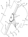
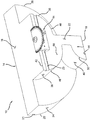
次に図1〜図4を参照すると、これらの図は較正装置10を示している。較正装置10は、標準試験片12と該標準試験片に摺動可能に取付けられた角度ゲージ14とを含む。標準試験片12は、上部案内面16、底部案内面18、前面20及び背面22を含む。1つの構成によると、角度ゲージ14は、溝21に取付けられて、前面20を横切って摺動可能である(図1参照)。別の構成によると、角度ゲージ14は、溝23に取付けられて、背面22を横切って摺動可能である(図2参照)。
Referring now to FIGS. 1-4, these figures show the
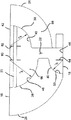
標準試験片12はさらに、複数の較正又は反射面を含む。反射面は、形が弓形であって、各々が確定半径を有する。反射面は弓形であるが、対比試験面は各々、検査しようとする構成部品の幾何学的形状に基づいて、その他の形状で形成できることを理解されたい。 The standard test strip 12 further includes a plurality of calibration or reflective surfaces. The reflective surfaces are arcuate in shape and each has a definite radius. It should be understood that although the reflective surface is arcuate, each of the contrast test surfaces can be formed in other shapes based on the geometric shape of the component being inspected.
第1の反射面24は、第1の半径(r1)によって定められ、また第2の反射面26は、第2の半径(r2)によって定められる。上部案内面16の前縁部28、底部案内面18の前縁部30並びにそれぞれ第1及び第2の反射面24、26の縁部32、34は、前面20の境界を定める。第3の反射面36は、第3の半径(r3)によって定められ、また第4の反射面38は、第4の半径(r4)によって定められる。第5の反射面40は、第5の半径(r5)によって定められる。上部案内面16の後縁部42、底部案内面18の後縁部44並びにそれぞれ第3、第4及び第5の反射面36、38、40の縁部46、48、50は、背面22の境界を定める。
The first
前面20に関連して言えば、第1のスクライブ線52は、第1の半径の中心点を示す。第2のスクライブ線54は、第2の半径の中心点を示す。第1のインデックス孔56が、第2の反射面26に隣接して前面20内に穿たれる。一連のスクライブ角度線58が、第1のインデックス孔56から前縁部28まで様々な角度で延びる。第1の角度線、第2の角度線及び第3の角度線は各々、垂直方向に対して40°、50°及び60°の角度で延びる。しかしながら、スクライブ角度線58の特定の角度は、設計要件に従って変更できることが分かるであろう。
With respect to the
背面22に関連して言えば、第3のスクライブ線60は、第3の半径の中心点を示し、第4のスクライブ線62は、第4の半径の中心点を示す。第5のスクライブ線64は、第5の半径の中心点を示す。第2のインデックス孔66が、第3の反射面36に隣接して背面22内に穿たれる。
With respect to the
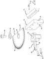
次に図5を参照すると、角度ゲージ14は、それに対してダブテールレール72と支持体74とが取付けられるスライドプレート70を含む。ダブテールレール72は、スライドプレート70の溝76内に嵌め込まれ、固締具78によって該溝76内に固定される。支持体74は、固締具82によってスライドプレート70の面80に隣接して固定される。支持体74は、穴84と、スクライブ線88を有する指示アーム86とを含む。角度プレート90が、支持体74上に回転可能に支持される。ダブテールレール72の拡がった側は、角度ゲージ14がそれぞれ前面20及び背面22を横切って摺動するのを可能にするように、溝21、23のいずれか内に嵌め込まれる。
Referring now to FIG. 5, the
固締具92が、皿又はスプリングワッシャ94と角度プレート90内に形成された孔96とを貫通して受けられる。固締具92は、穴84内に螺合されて角度プレート90を支持体74に固定する。スプリングワッシャ94は角度プレート90に対して十分な力を加えて、角度プレート90が固締具92の周りで望ましくない回転をするのを防止する。角度プレート90を回転させたい時には、操作者は、スプリングワッシャ94の力に抗して上向きの力を加え、角度プレート90を固締具92の周りで回転させる。角度プレート90をそこまで回転させる特定の角度は、線88を角度プレート90内にスクライブした角度マーカ96に整列させることによって決定される。角度プレート90はさらに、それに対する角度を求めようとする対象物と平行に整列させる位置合わせエッジ97を含む。
A
次に図6及び図7を参照しながら較正装置10の使用法について説明する。超音波振動子100は、最初に、ビームを空間内の点に集束させるための所望の誘導角(α)及びスキュー角(β)でプログラミングされる。必要とする特定の反射面に応じて、超音波振動子100を上部又は底部案内面16、18の1つ上に設置する。反射面は、構成部品の幾何学的形状に基づいて選択される。例えば、構成部品が2インチの外径を有する管である場合、4インチの半径を有する反射面を選択する。
Next, how to use the
図6及び図7の例示的な実施形態では、超音波振動子100は、上部案内面16上に設置されている。超音波振動子100のビームは、第2の反射面26に向かって方向付けられる。所望の増幅応答が得られるまで、超音波振動子100を、上部案内面16を横切って摺動させかつ上部案内面16上の所定の位置で回転させる。所望の振幅応答は、最大振幅応答とすることができる。しかしながら、最大振幅応答よりも小さい振幅応答でも、特定の材料分析には十分である場合があることが分かるであろう。そのような場合には、所望の振幅応答は、充足振幅応答として定められる。一例として、45°の誘導角の場合、所望の振幅応答は、超音波振動子100が第2の反射面26に対して45°である時に得られる。45°の場合には、超音波振動子100は、半径(r2)の中心点つまり第2のスクライブ線54とほぼ整列することになる。
In the exemplary embodiment of FIGS. 6 and 7, the
所望の振幅応答が得られたら、誘導角(α)とスキュー角(β)とが確認される。誘導角は、第1のインデックス孔56を用いて確認される。インデックス孔は、完全反射体である。その結果、所望の振幅応答は、第1のインデックス孔56に向けられたビームによって容易に識別される。誘導角は、角度線58に対して超音波振動子100の位置を比較することによって確認される。スキュー角は、角度ゲージ14を超音波振動子100に整列させることによって確認される。位置合わせエッジ97が超音波振動子100に隣接しかつ該超音波振動子100と平行になるまで、角度プレート90を回転させる。スキュー角は、線88が指している特定の角度マーカ96を目視することによって求められる。
Once the desired amplitude response is obtained, the induction angle (α) and the skew angle (β) are confirmed. The guide angle is confirmed using the
本発明の説明は、事実上単に例示的なものに過ぎず、従って本発明の要点から逸脱しない変更は、本発明の技術的範囲内にあることを意図している。なお、特許請求の範囲に記載された符号は、理解容易のためであってなんら発明の技術的範囲を実施例に限縮するものではない。 The description of the invention is merely exemplary in nature and, thus, changes that do not depart from the gist of the invention are intended to be within the scope of the invention. In addition, the code | symbol described in the claim is for easy understanding, and does not limit the technical scope of an invention to an Example at all.
10 較正装置
12 標準試験片
14 角度ゲージ
16 上部案内面
18 底部案内面
20 前面
21、23 溝
22 背面
24 第1の反射面
26 第2の反射面
36 第3の反射面
38 第4の反射面
40 第5の反射面
56 第1のインデックス孔
58 スクライブ角度線
66 第2のインデックス孔
70 角度ゲージブロック
86 指示アーム
90 角度プレート
97 位置合わせエッジ
100 超音波振動子
α 誘導角
β スキュー角
DESCRIPTION OF
Claims (8)
案内面(16、18)と、
前記案内面(16、18)の第1の側面(20)上で該案内面(16、18)に対して支持された角度ゲージ(14)と、
を含み、
前記角度ゲージ(14)が、前記案内面(16、18)上の前記超音波振動子(100)のスキュー角を測定するために調節可能である、
標準試験片(10)。 A standard specimen (10) for calibrating the ultrasonic transducer (100), comprising:
A guide surface (16, 18);
An angle gauge (14) supported against the guide surface (16, 18) on a first side surface (20) of the guide surface (16, 18);
Including
The angle gauge (14) is adjustable to measure the skew angle of the ultrasonic transducer (100) on the guide surface (16, 18);
Standard specimen (10).
前記超音波振動子(100)が、前記第1の較正面(24)に超音波を送るように前記案内面(16)上に載置されている、
請求項1記載の標準試験片(10)。 A first calibration surface (24) formed in the first side surface (20) of the guide surface (16);
The ultrasonic transducer (100) is placed on the guide surface (16) so as to send ultrasonic waves to the first calibration surface (24).
Standard test strip (10) according to claim 1.
前記超音波振動子(100)が、前記第2の較正面(26)に超音波を送るように前記案内面(16)上に載置されている、
請求項1記載の標準試験片(10)。 A second calibration surface (26) formed in the first side surface (20) of the guide surface (16);
The ultrasonic transducer (100) is placed on the guide surface (16) so as to send ultrasonic waves to the second calibration surface (26).
Standard test strip (10) according to claim 1.
前記超音波振動子(100)が、前記較正面(36、38、40)に超音波を送るように前記案内面(16、18)上に載置されている、
請求項7記載の標準試験片(10)。 A calibration surface (36, 38, 40) formed in the second side (22) of the guide surface (16, 18);
The ultrasonic transducer (100) is mounted on the guide surface (16, 18) so as to send ultrasonic waves to the calibration surface (36, 38, 40).
Standard test strip (10) according to claim 7.
Applications Claiming Priority (1)
| Application Number | Priority Date | Filing Date | Title |
|---|---|---|---|
| US10/680,185 US6938457B2 (en) | 2003-10-08 | 2003-10-08 | Phased array ultrasonic reference block |
Publications (2)
| Publication Number | Publication Date |
|---|---|
| JP2005114735A true JP2005114735A (en) | 2005-04-28 |
| JP2005114735A5 JP2005114735A5 (en) | 2007-11-22 |
Family
ID=34314098
Family Applications (1)
| Application Number | Title | Priority Date | Filing Date |
|---|---|---|---|
| JP2004294836A Pending JP2005114735A (en) | 2003-10-08 | 2004-10-07 | Phased-array ultrasonic reference block |
Country Status (4)
| Country | Link |
|---|---|
| US (1) | US6938457B2 (en) |
| EP (1) | EP1522848A1 (en) |
| JP (1) | JP2005114735A (en) |
| TW (1) | TW200517676A (en) |
Cited By (3)
| Publication number | Priority date | Publication date | Assignee | Title |
|---|---|---|---|---|
| KR101163549B1 (en) | 2008-10-23 | 2012-07-06 | 삼성중공업 주식회사 | Calibration block for phased-array ultrasonic inspection |
| KR101199717B1 (en) * | 2010-10-27 | 2012-11-08 | 한국수력원자력 주식회사 | The Phased Array Ultrasonic Testing Calibration Block for the Circumferential Scan Located at Tapered Weld and System for Measuring the Position of refracting angle and twisting angle using thereof |
| JP2013145235A (en) * | 2012-01-13 | 2013-07-25 | Airbus Operations Ltd | Calibration member and calibration method |
Families Citing this family (23)
| Publication number | Priority date | Publication date | Assignee | Title |
|---|---|---|---|---|
| US20090178465A1 (en) * | 2008-01-14 | 2009-07-16 | Ethridge Roger E | Acoustic transducer support frame and method |
| US7578166B2 (en) * | 2008-01-14 | 2009-08-25 | Grant Prideco, L.P. | Acoustic transducer calibration block and method |
| CN101650342B (en) * | 2009-09-05 | 2011-03-23 | 湖北新冶钢特种钢管有限公司 | Calibration test block and method for ultrasonic detection of large-sized steel ferrule finished product |
| US8521446B2 (en) * | 2010-11-23 | 2013-08-27 | Olympus Ndt Inc. | System and method of conducting refraction angle verification for phased array probes using standard calibration blocks |
| US9952182B2 (en) | 2010-12-10 | 2018-04-24 | Ihi Southwest Technologies | Visualization of tests on lift-type check valves using phased array sequence scanning |
| US9557303B2 (en) | 2010-12-10 | 2017-01-31 | Ihi Southwest Technologies, Inc. | Visualization of tests on swing type check valves using phased array sequence scanning |
| US10352477B2 (en) | 2010-12-10 | 2019-07-16 | Ihi Southwest Technologies, Inc. | Visualization of tests on globe-type valves using phased array sequence scanning |
| US8453508B2 (en) | 2010-12-10 | 2013-06-04 | Ihi Southwest Technologies, Inc. | Testing of swing type check valves using phased array sequence scanning |
| US10319484B1 (en) | 2011-11-17 | 2019-06-11 | Nuscale Power, Llc | Method for imaging a nuclear reactor |
| US10429356B2 (en) | 2012-01-31 | 2019-10-01 | General Electric Company | Method and system for calibrating an ultrasonic wedge and a probe |
| US9110000B2 (en) | 2012-02-17 | 2015-08-18 | General Electric Company | Method and system for determining the position of an ultrasonic wedge and a probe |
| CN102621236B (en) * | 2012-03-31 | 2014-09-10 | 南车戚墅堰机车车辆工艺研究所有限公司 | Test specimen and test method for testing performance of ultrasonic flaw detection probe |
| US9027404B2 (en) | 2012-05-17 | 2015-05-12 | Honeywell International Inc. | Ultrasonic non-destructive evaluation methods for friction-welded blisks |
| CN103954695B (en) * | 2014-04-23 | 2016-08-24 | 南京迪威尔高端制造股份有限公司 | A kind of heel test block |
| CN104297351B (en) * | 2014-10-29 | 2016-08-17 | 中广核检测技术有限公司 | A kind of test block for measuring ultrasonic wave angle probe refraction angle and measuring method thereof |
| WO2016153523A1 (en) | 2015-03-26 | 2016-09-29 | Halliburton Energy Services, Inc. | Cement evaluation with x-ray tomography |
| US10209398B2 (en) | 2015-03-26 | 2019-02-19 | Halliburton Energy Services, Inc. | Drilling fluid property determination |
| WO2016153524A1 (en) | 2015-03-26 | 2016-09-29 | Halliburton Energy Services, Inc. | Downhole tool apparatus, system, and methods |
| CN104777237B (en) * | 2015-04-10 | 2017-12-26 | 上海和伍精密仪器股份有限公司 | Low-voltage electrical apparatus electric contact ultrasonic examination test block assembly |
| CN105423965A (en) * | 2015-11-16 | 2016-03-23 | 南车戚墅堰机车车辆工艺研究所有限公司 | Locomotive vehicle axle crack depth measuring method |
| CN108845031A (en) * | 2018-05-04 | 2018-11-20 | 西南石油大学 | A kind of defect detection ultrasonic characteristic signal acquisition device |
| CN111413412B (en) * | 2019-01-04 | 2023-06-27 | 国电锅炉压力容器检验有限公司 | Method for measuring refraction angle of ultrasonic probe |
| CN111413413B (en) * | 2019-01-04 | 2023-06-27 | 国电锅炉压力容器检验有限公司 | Test block for measuring refraction angle of ultrasonic probe |
Citations (6)
| Publication number | Priority date | Publication date | Assignee | Title |
|---|---|---|---|---|
| JPS54161384A (en) * | 1978-06-09 | 1979-12-20 | Toshiba Corp | Reference device for ultrasonic flaw detection |
| JPH0220694Y2 (en) * | 1983-12-21 | 1990-06-05 | ||
| JPH08278297A (en) * | 1995-04-04 | 1996-10-22 | Hitachi Constr Mach Co Ltd | Reference flaw-detecting jig and ultrasonic flaw-detecting method using the jig |
| JPH1164298A (en) * | 1997-08-15 | 1999-03-05 | Mitsubishi Heavy Ind Ltd | Ultrasonic oblique angle flaw detecting apparatus |
| JPH11183445A (en) * | 1997-12-19 | 1999-07-09 | Mitsubishi Heavy Ind Ltd | Flaw detector |
| JP2001221784A (en) * | 2000-02-08 | 2001-08-17 | Japan Steel Works Ltd:The | Ultrasonic skew angle probe |
Family Cites Families (8)
| Publication number | Priority date | Publication date | Assignee | Title |
|---|---|---|---|---|
| US3186216A (en) * | 1961-11-09 | 1965-06-01 | Dickinson Ben Wade Oakes | Method and apparatus for generating and receiving ultrasonic helical waves |
| US5036707A (en) * | 1990-03-12 | 1991-08-06 | The Boc Group, Inc. | Ultrasonic testing apparatus and method for rapidly inspecting a large number of gas cylinders of similar design for internal neck-shoulder defects |
| US5665893A (en) * | 1996-06-06 | 1997-09-09 | General Electric Company | Reference block for determining operating characteristics of ultrasonic transducer in right circular cylinder type probe |
| US5837880A (en) * | 1997-08-20 | 1998-11-17 | Sperry Rail Service, Inc. | Compact ultrasonic calibration block |
| JPH11337536A (en) * | 1998-05-28 | 1999-12-10 | Hitachi Constr Mach Co Ltd | Calibration auxiliary tool for reference specimen |
| US6415644B1 (en) * | 1999-04-29 | 2002-07-09 | General Electric Company | Ultrasonic calibration apparatus |
| DE10115549A1 (en) * | 2001-03-28 | 2002-10-02 | Heidenhain Gmbh Dr Johannes | Angle measuring device and its use |
| US6532675B2 (en) * | 2001-04-18 | 2003-03-18 | Guy Letourneau | Device for measuring the angle of orientation with reference to a known frame of reference between a first object having a first axis and a second remote destination |
-
2003
- 2003-10-08 US US10/680,185 patent/US6938457B2/en not_active Expired - Fee Related
-
2004
- 2004-09-27 TW TW093129287A patent/TW200517676A/en unknown
- 2004-10-07 JP JP2004294836A patent/JP2005114735A/en active Pending
- 2004-10-08 EP EP04256245A patent/EP1522848A1/en not_active Withdrawn
Patent Citations (6)
| Publication number | Priority date | Publication date | Assignee | Title |
|---|---|---|---|---|
| JPS54161384A (en) * | 1978-06-09 | 1979-12-20 | Toshiba Corp | Reference device for ultrasonic flaw detection |
| JPH0220694Y2 (en) * | 1983-12-21 | 1990-06-05 | ||
| JPH08278297A (en) * | 1995-04-04 | 1996-10-22 | Hitachi Constr Mach Co Ltd | Reference flaw-detecting jig and ultrasonic flaw-detecting method using the jig |
| JPH1164298A (en) * | 1997-08-15 | 1999-03-05 | Mitsubishi Heavy Ind Ltd | Ultrasonic oblique angle flaw detecting apparatus |
| JPH11183445A (en) * | 1997-12-19 | 1999-07-09 | Mitsubishi Heavy Ind Ltd | Flaw detector |
| JP2001221784A (en) * | 2000-02-08 | 2001-08-17 | Japan Steel Works Ltd:The | Ultrasonic skew angle probe |
Cited By (3)
| Publication number | Priority date | Publication date | Assignee | Title |
|---|---|---|---|---|
| KR101163549B1 (en) | 2008-10-23 | 2012-07-06 | 삼성중공업 주식회사 | Calibration block for phased-array ultrasonic inspection |
| KR101199717B1 (en) * | 2010-10-27 | 2012-11-08 | 한국수력원자력 주식회사 | The Phased Array Ultrasonic Testing Calibration Block for the Circumferential Scan Located at Tapered Weld and System for Measuring the Position of refracting angle and twisting angle using thereof |
| JP2013145235A (en) * | 2012-01-13 | 2013-07-25 | Airbus Operations Ltd | Calibration member and calibration method |
Also Published As
| Publication number | Publication date |
|---|---|
| US6938457B2 (en) | 2005-09-06 |
| US20050076703A1 (en) | 2005-04-14 |
| TW200517676A (en) | 2005-06-01 |
| EP1522848A1 (en) | 2005-04-13 |
Similar Documents
| Publication | Publication Date | Title |
|---|---|---|
| JP2005114735A (en) | Phased-array ultrasonic reference block | |
| US7966860B2 (en) | Method for configuring an array of transducers in an ultrasonic test apparatus | |
| US9863826B2 (en) | Sensor device and residual stress detection system employing same | |
| US6415644B1 (en) | Ultrasonic calibration apparatus | |
| CN106017371B (en) | The measuring device and its method of surface defect opening width based on laser-ultrasound | |
| CN105229461B (en) | For the device and method of the especially live nondestructive inspection of tubular products | |
| US9804129B2 (en) | Apparatus for inspecting a tube | |
| US20130151171A1 (en) | Ultrasonic Inspection Method, Ultrasonic Test Method and Ultrasonic Inspection Apparatus | |
| CN106290583A (en) | A kind of ultrasonic phase array detection Small-diameter Tube Seams Special test block | |
| CN107421475A (en) | A kind of supersonic detection device for being used for thin-wall steel tube layered weighting and thickness measuring | |
| Mogilner et al. | Ultrasonic flaw detection: adjustment and calibration of equipment using samples with cylindrical drilling | |
| US20140352438A1 (en) | Device for ultrasonic inspection | |
| JP2012021930A (en) | Thickness measuring method | |
| CN207066372U (en) | A kind of supersonic detection device for being used for thin-wall steel tube layered weighting and thickness measuring | |
| US11255652B2 (en) | Methods and apparatus for determining a height of an edge portion of a product | |
| RU2310838C2 (en) | Device for adjusting ultrasonic converters-defectoscopes | |
| JP2018077097A (en) | Ultrasonic flaw searching method, and ultrasonic flaw searching device | |
| KR100602769B1 (en) | A reference block for ultrasonic testing | |
| CN112326799A (en) | Method for applying phased array technology to pressure pipeline regular inspection and grading | |
| RU2488108C2 (en) | Method of ultrasonic control of butt, lap and tee welds of thin-walled pipes of small diameter | |
| KR20110033609A (en) | Calibration block for ultrasonic testing with tapered and curved surface | |
| CN109060965B (en) | Special reference test block for ultrasonic detection of longitudinal wave of fir-type blade root axially assembled by steam turbine | |
| Ray et al. | Sensitivity of simulated flaw-height estimates to phased array scan parameters | |
| JP6601793B2 (en) | Underwater bolt inspection jig and underwater bolt inspection method | |
| KR101258915B1 (en) | Extracting method for pipe cutting line |
Legal Events
| Date | Code | Title | Description |
|---|---|---|---|
| A521 | Written amendment |
Free format text: JAPANESE INTERMEDIATE CODE: A523 Effective date: 20071004 |
|
| A621 | Written request for application examination |
Free format text: JAPANESE INTERMEDIATE CODE: A621 Effective date: 20071004 |
|
| A977 | Report on retrieval |
Free format text: JAPANESE INTERMEDIATE CODE: A971007 Effective date: 20091208 |
|
| A131 | Notification of reasons for refusal |
Free format text: JAPANESE INTERMEDIATE CODE: A131 Effective date: 20091215 |
|
| A02 | Decision of refusal |
Free format text: JAPANESE INTERMEDIATE CODE: A02 Effective date: 20100601 |