JP2005100748A - Electrolyte membrane electrode bonded laminate, its manufacturing method as well as solid polymer fuel cell - Google Patents
Electrolyte membrane electrode bonded laminate, its manufacturing method as well as solid polymer fuel cell Download PDFInfo
- Publication number
- JP2005100748A JP2005100748A JP2003331557A JP2003331557A JP2005100748A JP 2005100748 A JP2005100748 A JP 2005100748A JP 2003331557 A JP2003331557 A JP 2003331557A JP 2003331557 A JP2003331557 A JP 2003331557A JP 2005100748 A JP2005100748 A JP 2005100748A
- Authority
- JP
- Japan
- Prior art keywords
- layer
- conductive carbon
- electrolyte membrane
- diffusion layer
- membrane electrode
- Prior art date
- Legal status (The legal status is an assumption and is not a legal conclusion. Google has not performed a legal analysis and makes no representation as to the accuracy of the status listed.)
- Pending
Links
Images


Classifications
-
- Y—GENERAL TAGGING OF NEW TECHNOLOGICAL DEVELOPMENTS; GENERAL TAGGING OF CROSS-SECTIONAL TECHNOLOGIES SPANNING OVER SEVERAL SECTIONS OF THE IPC; TECHNICAL SUBJECTS COVERED BY FORMER USPC CROSS-REFERENCE ART COLLECTIONS [XRACs] AND DIGESTS
- Y02—TECHNOLOGIES OR APPLICATIONS FOR MITIGATION OR ADAPTATION AGAINST CLIMATE CHANGE
- Y02E—REDUCTION OF GREENHOUSE GAS [GHG] EMISSIONS, RELATED TO ENERGY GENERATION, TRANSMISSION OR DISTRIBUTION
- Y02E60/00—Enabling technologies; Technologies with a potential or indirect contribution to GHG emissions mitigation
- Y02E60/30—Hydrogen technology
- Y02E60/50—Fuel cells
-
- Y—GENERAL TAGGING OF NEW TECHNOLOGICAL DEVELOPMENTS; GENERAL TAGGING OF CROSS-SECTIONAL TECHNOLOGIES SPANNING OVER SEVERAL SECTIONS OF THE IPC; TECHNICAL SUBJECTS COVERED BY FORMER USPC CROSS-REFERENCE ART COLLECTIONS [XRACs] AND DIGESTS
- Y02—TECHNOLOGIES OR APPLICATIONS FOR MITIGATION OR ADAPTATION AGAINST CLIMATE CHANGE
- Y02P—CLIMATE CHANGE MITIGATION TECHNOLOGIES IN THE PRODUCTION OR PROCESSING OF GOODS
- Y02P70/00—Climate change mitigation technologies in the production process for final industrial or consumer products
- Y02P70/50—Manufacturing or production processes characterised by the final manufactured product
Abstract
Description
本発明は、電解質膜に高分子を用いた電解質膜電極接合体及びその製造方法、該電解質膜電極接合体を構成要素とする、固体高分子型燃料電池に関するものである。 The present invention relates to an electrolyte membrane electrode assembly using a polymer as an electrolyte membrane, a method for producing the same, and a solid polymer fuel cell having the electrolyte membrane electrode assembly as a constituent element.
燃料電池は、実質的には発電機であり、水の電気分解の、逆の反応を利用して電気を取り出すものである。そして、従来の発電方法に比較して高い効率で電気エネルギーを取り出すことが可能なので、省資源などの観点から、様々な技術開発がなされ、実用化されつつある。 A fuel cell is essentially a generator and takes out electricity using the reverse reaction of water electrolysis. And since electric energy can be taken out with high efficiency compared with the conventional power generation method, various technical development is made | formed and put into practical use from a viewpoint of resource saving.
燃料電池の基本的な構造は、水素イオンを通す電解質膜、電解質膜の両側に配置された燃料極と酸素極からなる電極、電極から電気を取り出す集電体、電極への燃料や空気の供給路を仕切り、前記の要素をセルユニットとして構成するとともに、セルユニット間を電気的に接続するセパレータからなる。 The basic structure of a fuel cell consists of an electrolyte membrane that allows hydrogen ions to pass through, an electrode composed of a fuel electrode and an oxygen electrode arranged on both sides of the electrolyte membrane, a current collector that extracts electricity from the electrode, and fuel and air supply to the electrode It consists of a separator that partitions the path and configures the above-described elements as cell units and electrically connects the cell units.
そして、電解質膜を構成する材料の種類により溶融炭酸塩型、固体酸化物型、リン酸型、固体高分子型に分類される。これらの用途を決定する特性として作動温度があり、固体高分子型は、約80℃という作動温度の低さのために特に注目され、モバイル機器用などにも使用できる可能性が高い。 And it is classified into a molten carbonate type, a solid oxide type, a phosphoric acid type, and a solid polymer type according to the kind of material constituting the electrolyte membrane. The operating temperature is a characteristic that determines these applications, and the solid polymer type is particularly noted for its low operating temperature of about 80 ° C., and is likely to be used for mobile devices and the like.
図8は、基本的な、従来の固体高分子型燃料電池の構造を示す斜視図である。図8において、1は電解質膜、21は電極であり、電解質膜1を両面から挟んで接合され、電解質膜電極接合体(Membrane Electrode Assembly:以下、MEAと記す)を構成する。MEAにおける電極21は、触媒層、拡散層を積層したもので、燃料、酸素を供給することにより、電気化学反応が起こり、電力が得られる。
FIG. 8 is a perspective view showing the structure of a basic conventional polymer electrolyte fuel cell. In FIG. 8, 1 is an electrolyte membrane, and 21 is an electrode, which are joined by sandwiching the
また、22はセパレータであり、全面に溝が設けられている。セパレータ22は、MEAを両側から挟み、圧力を加えて固定し、反応物の供給、生成物の排出、集電の機能を備えている。材質としては、導電性が必要なため、グラファイトやステンレスが用いられ、溝を通して、反応物の供給と生成物の排出を行う。なお、矢印は、燃料または酸素を供給する方向を示す。
一般的に、固体高分子型燃料電池におけるMEAは、電極と、プロトン伝導性固体高分子電解質膜とを、熱プレスにより接合することにより作製される。そして電極は、導電性を有する繊維の抄紙体などからなる電極基材に、導電性カーボンと疎水性高分子を混合、分散したペーストを拡散層として塗布し、その上に、貴金属触媒を担持した導電性カーボンと電解質溶液を混合したペーストを、触媒層として塗布する、という方法で得られる。また、電解質溶液としては、固体電解質膜を構成する高分子の溶液が用いられることが多い。 In general, the MEA in a polymer electrolyte fuel cell is produced by joining an electrode and a proton conductive solid polymer electrolyte membrane by hot pressing. The electrode is coated with a paste in which conductive carbon and hydrophobic polymer are mixed and dispersed as a diffusion layer on an electrode base material made of conductive paper or the like, and a noble metal catalyst is supported thereon. A paste obtained by mixing conductive carbon and an electrolyte solution is obtained by applying as a catalyst layer. Moreover, as the electrolyte solution, a polymer solution constituting the solid electrolyte membrane is often used.
固体高分子型燃料電池においては、外部からMEAに供給された燃料、酸素は、電極基材、拡散層を通過し触媒層で電気化学的反応を起こし電力が発生する。その反応で生成された、水、二酸化炭素は、逆に触媒層から拡散層、電極基材を通過し外部に排出される。この際、供給、排出が滞りなく行われることが、発電特性の向上につながり、その通過経路にあたる電極基材、特に酸素極側では、拡散層に、水を円滑に排出する性能が要求される。 In the polymer electrolyte fuel cell, fuel and oxygen supplied to the MEA from the outside pass through the electrode base material and the diffusion layer, cause an electrochemical reaction in the catalyst layer, and generate electric power. On the contrary, water and carbon dioxide generated by the reaction are discharged from the catalyst layer to the outside through the diffusion layer and the electrode substrate. In this case, supply and discharge are performed without delay, leading to improvement of power generation characteristics, and on the electrode base material, particularly the oxygen electrode side, which is the passage route, the diffusion layer is required to have a performance of smoothly discharging water. .
このように、電極基材、拡散層に求められる主な性能は、反応物、生成物を、迅速に供給、排出する経路を具備すること、撥水性、電子伝導性、化学的安定性である。このような要求を満たすために、電極基材、拡散層には、様々な検討が行われている。 Thus, the main performance required for the electrode substrate and the diffusion layer is to provide a route for rapidly supplying and discharging the reactants and products, water repellency, electronic conductivity, and chemical stability. . In order to satisfy such requirements, various studies have been made on electrode base materials and diffusion layers.
これに対応した技術の例が、下記特許文献1、特許文献2、特許文献3、特許文献4、特許文献5に開示されている。
Examples of technologies corresponding to this are disclosed in the following
特許文献1及び特許文献2には、セルロース繊維とポリビニルアルコールからなる抄紙体や、炭化した抄紙体をピッチなどで結着したシートを、熱処理により炭化して、拡散層や電極を製造する技術が開示されている。しかし、この技術による、拡散層や電極は、バインダーも炭化させてしまうため、脆弱で、耐久性や加工性が低下するという問題がある。また、このような構成の拡散層に、直接塗布法で触媒層を形成しようとすると、浸み込みにより、所要の触媒層形成が困難になるという問題がある。
特許文献3及び特許文献4には、拡散層の材料構成、形成方法の例が開示されている。これらに開示されている拡散層は、先に述べたような電極基材に、導電性カーボンと疎水性高分子を混合したペーストを塗布することにより形成されるため、その物理的性質は利用する電極基材の性質に依存するものになる。
そのため、電極基材に炭素繊維からなる繊維状カーボンシートなどを利用した場合、結局は破損し易い構造になってしまう。また、使用する材料によっては、塗布膜にひび割れが発生することがあり、再現性良く製造することが出来ない、電極基材との接合性が悪いために拡散層と電極基材界面での電気抵抗が大きくなってしまうなどの問題がある。 Therefore, when a fibrous carbon sheet made of carbon fiber or the like is used for the electrode base material, the structure tends to be easily damaged. Depending on the material used, cracks may occur in the coating film, which cannot be produced with good reproducibility, and because the bondability with the electrode substrate is poor, the electrical properties at the interface between the diffusion layer and the electrode substrate There are problems such as increased resistance.
特許文献5には、シート状拡散層とその製造方法が開示されている。この例では、拡散層の厚みが厚いという問題と、拡散層を構成する導電性カーボンとして、粒状カーボン、繊維状カーボンが使用されているが、単純に混合されシート化されているだけであり、拡散効果の向上は不十分であるという問題がある。
前記のように、従来のMEAは、電極基材自体が炭素繊維を炭素で結着させたものであり、脆弱で耐久性が低いこと、拡散層と電極基材界面での電気抵抗が大きいことなどの理由で、燃料電池の性能向上には検討の余地がある。また製造工程においては、特に疎水性高分子として、ポリテトラフルオロエチレン(以下、PTFEと記す)を用いた場合に、導電性カーボンと疎水性高分子を分散したペーストを塗布しただけでは、亀裂の発生が多く、均一な再現性の良い膜を得るのが困難であるという問題がある。さらに、PTFEは繊維状の方が、撥水性が向上するので、塗布しただけでは、その特性を十分に活用できていないのが現状である。 As described above, the conventional MEA has a carbon fiber bonded with carbon in the electrode base material itself, is brittle and has low durability, and has a large electric resistance at the interface between the diffusion layer and the electrode base material. For these reasons, there is room for study to improve the performance of fuel cells. In addition, in the manufacturing process, when polytetrafluoroethylene (hereinafter referred to as PTFE) is used as the hydrophobic polymer, cracking may not occur if only a paste in which conductive carbon and hydrophobic polymer are dispersed is applied. There is a problem that it is difficult to obtain a film having a large number of occurrences and uniform reproducibility. Furthermore, since PTFE is more fibrous in terms of water repellency, its properties cannot be fully utilized by simply applying it.
また、前述したように、燃料と酸素の反応が、触媒層への反応物の拡散過程が律速にならないようにし、生成物を速やかに排出することが、固体高分子型燃料電池の性能向上の要因となる。そのためには、特に拡散層の改良が必要で、使用される導電性カーボン、疎水性高分子の構成には、さらに検討の必要がある。 Further, as described above, the reaction between the fuel and oxygen prevents the diffusion process of the reactants to the catalyst layer from becoming rate-limiting, and the product is discharged quickly, which improves the performance of the polymer electrolyte fuel cell. It becomes a factor. For this purpose, it is necessary to improve the diffusion layer, and the structure of the conductive carbon and hydrophobic polymer to be used needs further investigation.
従って、本発明の課題は、固体高分子型燃料電池に用いられるMEAの、機械的な強度を向上するとともに、反応物及び生成物の、供給及び排出を迅速化し、併せてこのMEAを構成要素とする、固体高分子型燃料電池の信頼性を向上し、高性能化することにある。 Accordingly, an object of the present invention is to improve the mechanical strength of the MEA used in the polymer electrolyte fuel cell, speed up the supply and discharge of the reactants and products, and also configure the MEA as a component. It is to improve the reliability of the polymer electrolyte fuel cell and to improve the performance.
本発明は、前記の問題を解決するために、MEAの拡散層に用いる材料とその構成を再検討した結果なされたものである。 The present invention has been made as a result of reexamination of materials used for the diffusion layer of MEA and the structure thereof in order to solve the above-mentioned problems.
即ち、本発明は、導電性カーボンと疎水性高分子を含み、可撓性を具備したシートからなる単位層を複数積層した構造の拡散層及び該拡散層に接する触媒層を含む燃料極及び酸素極の電極と、固体電解膜とを有する、固体高分子型燃料電池の電解質膜電極接合体であって、前記単位層に含まれる前記導電性カーボンが、層ごとに形状と大きさが異なることを特徴とするMEAである。 That is, the present invention relates to a fuel electrode and oxygen including a diffusion layer having a structure in which a plurality of unit layers made of a sheet including conductive carbon and a hydrophobic polymer and having flexibility, and a catalyst layer in contact with the diffusion layer. An electrolyte membrane electrode assembly of a polymer electrolyte fuel cell having an electrode and a solid electrolyte membrane, wherein the conductive carbon contained in the unit layer has a different shape and size for each layer It is MEA characterized by these.
また、本発明は、触媒層に近い側の前記単位層に含まれる前記導電性カーボンが、粒状導電性カーボンであり、触媒層から離れた側の前記単位層に含まれる導電性カーボンが、繊維状導電性カーボンで、かつ、触媒層から、より離れた位置に配置される炭層の方が、含まれる前記繊維状導電性カーボンの平均繊維長さ及び平均繊維径が大きいことを特徴とする、前記のMEAである。 In the present invention, the conductive carbon contained in the unit layer on the side close to the catalyst layer is granular conductive carbon, and the conductive carbon contained in the unit layer on the side away from the catalyst layer is a fiber. The conductive carbon and the carbon layer disposed at a position further away from the catalyst layer are characterized in that the average fiber length and average fiber diameter of the fibrous conductive carbon contained are larger, Said MEA.
また、本発明は、前記疎水性高分子の種類と、前記疎水性高分子と前記導電性カーボンの混合比率が、前記単位層ごとに異なることを特徴とする、前記のMEAである。 Further, the present invention is the above MEA, wherein the type of the hydrophobic polymer and the mixing ratio of the hydrophobic polymer and the conductive carbon are different for each unit layer.
また、本発明は、前記拡散層が、電極を構成する基材として機能することを特徴とする、前記のMEAである。 Moreover, this invention is said MEA, The said diffusion layer functions as a base material which comprises an electrode.
また、本発明は、燃料極側に、前記拡散層の代替として、繊維状導電性カーボンの抄紙体に、浸み込み防止層と触媒層を形成したシートを用いることを特徴とする、前記のMEAである。 Further, the present invention is characterized in that, on the fuel electrode side, as a substitute for the diffusion layer, a sheet in which an infiltration prevention layer and a catalyst layer are formed on a fibrous conductive carbon papermaking body is used. MEA.
また、本発明は、導電性カーボンと疎水性子分子を混合、シート成形することにより、単位層を調製し、該単位層をそのまま拡散層とする工程、または、該単位層の複数枚を積層して一体化し、多層構造の拡散層を製造する工程を含む電解質膜電極接合体の製造方法であって、前記単位層は、含まれる導電性カーボンの形状及び大きさと、疎水性高分子の材質の少なくともいずれかが、単位層ごとに異なることを特徴とする、前記のMEAの製造方法ある。 The present invention also includes a step of preparing a unit layer by mixing conductive carbon and hydrophobic child molecules and forming a sheet, and using the unit layer as a diffusion layer as it is, or laminating a plurality of the unit layers. The unit membrane is formed of a conductive polymer shape and size, and a hydrophobic polymer material. The method includes a step of manufacturing a diffusion layer having a multilayer structure. The MEA manufacturing method is characterized in that at least one of them differs for each unit layer.
また、本発明は、前記のMEAを有することを特徴とする固体高分子型燃料電池である。 The present invention also provides a polymer electrolyte fuel cell comprising the MEA.
本発明のMEAにおいて、拡散層が、従来のように導電性カーボンと疎水性高分子を混合したペーストを電極基材に塗布して構成したものはなく、導電性カーボンを疎水性高分子に分散した混和物から形成した、可撓性を有するシートである。このため、従来のような脆弱さがなく、導電性カーボンに起因する導電性を有するので、別途に電極基材を設ける必要がなく、拡散層と電極基材界面の接触抵抗がないので、電気伝導性を向上できることを特徴とする。 In the MEA of the present invention, there is no diffusion layer formed by applying a paste in which conductive carbon and a hydrophobic polymer are mixed to the electrode base material as in the past, and the conductive carbon is dispersed in the hydrophobic polymer. It is a flexible sheet formed from the blend. For this reason, there is no brittleness as in the prior art, and it has conductivity due to conductive carbon, so there is no need to provide a separate electrode base material, and there is no contact resistance between the diffusion layer and the electrode base material. It is characterized in that the conductivity can be improved.
また、拡散層をシート状に形成するため、塗布法のようなひび割れも起こらず、均一で再現性が良好な拡散層を得ることが出来る。さらに、疎水性高分子としてPTFEを用いた場合、シート状にロールで加工する際に、PTFE粒子が引き伸ばされ繊維化するため、拡散層に十分な疎水性を付与できるという効果が得られる。 Further, since the diffusion layer is formed in a sheet shape, a uniform diffusion layer with good reproducibility can be obtained without causing cracks as in the coating method. Furthermore, when PTFE is used as the hydrophobic polymer, the PTFE particles are stretched and fiberized when processed into a sheet shape by a roll, so that an effect of imparting sufficient hydrophobicity to the diffusion layer can be obtained.
また、拡散層シートを、異なる種類の導電性カーボン、異なる疎水性高分子を用いた、異なる材料構成の複数のシートを一体化するという方法で、多層構造とすることにより、拡散性、強度を向上させたことを特徴とする。 In addition, the diffusion layer sheet has a multi-layer structure by integrating a plurality of sheets of different material configurations using different types of conductive carbon and different hydrophobic polymers, thereby improving diffusibility and strength. It is characterized by improvement.
本発明のMEAにおいては、拡散層シートに、粒状の導電性カーボンと、繊維状の導電性カーボンを用いる。粒状導電性カーボンとしては、粒径が0.02〜10μmのものが好ましく、より好ましくは、0.02〜1μmであり、繊維状導電性カーボンとしては、繊維径が0.05〜20μm、繊維長10μm〜10mmのものが好ましい。 In the MEA of the present invention, granular conductive carbon and fibrous conductive carbon are used for the diffusion layer sheet. The granular conductive carbon preferably has a particle diameter of 0.02 to 10 μm, more preferably 0.02 to 1 μm, and the fibrous conductive carbon has a fiber diameter of 0.05 to 20 μm and fibers. Those having a length of 10 μm to 10 mm are preferred.
粒状導電性カーボンとしては、アセチレンブラック、ケッチェンブラック、ファーネスブラック、サーマルブラックなどが使用可能で、繊維状導電性カーボンとしては、セルロース系、ポリアクリロニトリル系、ピッチ系などの炭素繊維が使用可能である。また、気相法などで得られるカーボンナノファイバなどを用いることもできる。 As the granular conductive carbon, acetylene black, ketjen black, furnace black, thermal black, etc. can be used. As the fibrous conductive carbon, carbon fibers such as cellulose, polyacrylonitrile, pitch can be used. is there. Moreover, carbon nanofibers obtained by a vapor phase method or the like can also be used.
疎水性高分子としては、PTFE、ポリフッ化ビニリデン(以下、PVDFと記す)、ヘキサフルオロプロピレン−テトラフルオロエチレン共重合体(以下、FEPと記す)などが使用できる。また、これらを混合して用いることも可能である。これらの疎水性高分子の場合、PTFE、FEPでは、平均粒径が0.1〜0.2μmの微粉末を、水に50〜60重量%分散させたディスパージョンを用いることが好ましく、PVDFは、シクロヘキサノンやジメチルホルムアミドなどの溶媒に溶解させた溶液を用いることが好ましい。 As the hydrophobic polymer, PTFE, polyvinylidene fluoride (hereinafter referred to as PVDF), hexafluoropropylene-tetrafluoroethylene copolymer (hereinafter referred to as FEP), or the like can be used. Moreover, it is also possible to mix and use these. In the case of these hydrophobic polymers, it is preferable to use a dispersion in which fine powder having an average particle size of 0.1 to 0.2 μm is dispersed in water by 50 to 60% by weight in PTFE and FEP. It is preferable to use a solution dissolved in a solvent such as cyclohexanone or dimethylformamide.
これらの導電性カーボンと疎水性高分子の混合比は、疎水性高分子が多いと疎水性は向上するが、電子伝導度が低下する。逆に、少ないと電子伝導度の低下が抑えられるが、疎水性は低下してしまう。これらを考慮すると、疎水性高分子の混合比は、5〜30重量%が好ましく、より好ましくは、10〜20重量%である。 As for the mixing ratio of these conductive carbon and hydrophobic polymer, when the amount of hydrophobic polymer is large, the hydrophobicity is improved, but the electronic conductivity is lowered. On the other hand, if the amount is small, the decrease in electron conductivity is suppressed, but the hydrophobicity is decreased. Considering these, the mixing ratio of the hydrophobic polymer is preferably 5 to 30% by weight, and more preferably 10 to 20% by weight.
実際の製造工程は、上記の混合比になるように、導電性カーボンと、疎水性高分子のディスパージョンまたは溶液を秤量して、混合、分散してペーストを作製し、シート状に加工する。ただし、疎水性高分子としてPTFEを用いる場合は、混合、分散した後、濾過、乾燥して、導電性カーボンと疎水性高分子からなる複合粉末を得て、その複合粉末を、ソルベントナフサなどの溶媒を使用してシート状にする方法もある。また、焼成が必要なものに対しては、マッフル炉、もしくは、熱プレスによる加熱、圧縮を行う。 In an actual manufacturing process, conductive carbon and a dispersion or solution of a hydrophobic polymer are weighed, mixed and dispersed to produce a paste so as to have the above mixing ratio, and processed into a sheet. However, when PTFE is used as the hydrophobic polymer, it is mixed, dispersed, filtered and dried to obtain a composite powder composed of conductive carbon and a hydrophobic polymer, and the composite powder is used as a solvent naphtha or the like. There is also a method of forming a sheet using a solvent. For those that require firing, heating and compression are performed using a muffle furnace or a hot press.
このようにして作製されるシートの厚みは、50〜200μmが好ましく、より好ましくは、50〜150μmである。その理由は、この範囲より薄い場合は、拡散性、電子伝導度は高いが、強度が低下し、この範囲より厚い場合は、強度は向上するが、拡散性、電子伝導度が低下してしまうからである。 The thickness of the sheet thus prepared is preferably 50 to 200 μm, and more preferably 50 to 150 μm. The reason is that if the thickness is smaller than this range, the diffusibility and electron conductivity are high, but the strength is reduced. If the thickness is thicker than this range, the strength is improved, but the diffusivity and electron conductivity are decreased. Because.
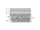
図1は、本発明のMEAの一例の断面を、模式的に示す図である。図1において、1は電解質膜、2は触媒層、3は粒状の導電性カーボンを含む第1の単位層、4は繊維状の導電性カーボンを含む第2の単位層、5は繊維状の導電性カーボンを含む第3の単位層、6は拡散層、7は電極である。第1の単位層3、第2の単位層4、第3の単位層5は一体化され、拡散層6を形成していて、繊維状の導電性カーボンの繊維径と長さは、第2の単位層4よりも第3の単位層5の方が大きくなっている。
FIG. 1 is a diagram schematically showing a cross section of an example of the MEA of the present invention. In FIG. 1, 1 is an electrolyte membrane, 2 is a catalyst layer, 3 is a first unit layer containing granular conductive carbon, 4 is a second unit layer containing fibrous conductive carbon, and 5 is a fibrous unit. A third unit layer containing conductive carbon, 6 is a diffusion layer, and 7 is an electrode. The
また、第1の単位層3を構成する粒状の導電性カーボンを、粒子間の間隙ができるだけ少なくなるような粒度分布にすることで、塗布法により触媒層2を形成する工程で、塗布に用いるペーストが内部に浸み込むことを極めて少なくすることができる。これによって、所要の触媒層が容易に形成でき、第1の単位層3は浸み込み防止層として機能することができる。
Further, the granular conductive carbon constituting the
このような多層構造の拡散層シートを作製する方法は、特に限定されるものではないが、前記のように、疎水性高分子のディスパージョンまたは溶液に導電性カーボンを混合、分散させたペースを基材に塗布して成膜することで、それぞれの単位層のシートを作製し、それらを重ね合わせ、圧縮することにより1枚の拡散層シートとすることができる。 A method for producing such a diffusion layer sheet having a multi-layer structure is not particularly limited. As described above, a pace in which conductive carbon is mixed and dispersed in a dispersion or solution of a hydrophobic polymer is used. By coating on a substrate and forming a film, a sheet of each unit layer is produced, and a single diffusion layer sheet can be obtained by overlapping and compressing them.
また、触媒として、燃料極にはPtRu担持カーボン触媒、酸素極にはPt担持カーボン触媒を用い、これらの触媒と、プロトン伝導経路かつ触媒層の結着剤として機能する固体電解質の溶液を混合し、触媒層形成用のペーストとして、前記拡散層に塗布乾燥することで電極7を作製し、本発明のMEAを得ることができる。
As the catalyst, a PtRu-supported carbon catalyst is used for the fuel electrode, and a Pt-supported carbon catalyst is used for the oxygen electrode, and these catalysts are mixed with a solution of a solid electrolyte that functions as a proton conduction path and a catalyst layer binder. The
なお、固体電解質としては、ポリパーフルオロスルホン酸を用いることができ、具体的には、デュポン社のNafion(登録商標)を挙げることができる。本発明のMEAにおいては、触媒の塗布量は、酸素極が1mg/cm2、燃料極が2〜4mg/cm2であるが、特にこの範囲に限定されるものではない。 Note that polyperfluorosulfonic acid can be used as the solid electrolyte, and specific examples include Nafion (registered trademark) manufactured by DuPont. In the MEA of the present invention, the coating amount of the catalyst, the oxygen electrode is 1 mg / cm 2, the fuel electrode is 2-4 mg / cm 2, but is not particularly limited to this range.
このようにして作製した、燃料極用、酸素極用1対の電極で、固体電解質膜を挟み、熱プレスをすることにより接合し、MEAとした。なお、固体電解質膜としても、前記のNafionは優れた特性を有し、好適に使用できる。また、熱プレスの条件は圧力10MPa、温度130℃、時間1分、MEAの大きさは、35×35mmである。固体電解質膜、熱プレス条件、MEAの大きさは特に限定されるものではない。
The solid electrolyte membrane was sandwiched between a pair of electrodes for the fuel electrode and oxygen electrode produced in this way, and joined by hot pressing to obtain an MEA. Note that the Nafion has excellent characteristics and can be suitably used as a solid electrolyte membrane. Moreover, the conditions of hot press are pressure 10MPa, temperature 130 degreeC,
得られたMEAの評価は、現在、携帯用燃料電池として最も注目されているメタノールと水を燃料とし、触媒層で直接反応させるダイレクトメタノール型燃料電池方式で、なおかつ、ポンプを用いず燃料、酸素の供給を行う方式で行った。特に酸素極では、生成水が溜まるフラッディング現象による出力の低下が起こりやすく、拡散層の効果が重要とされる。ただし、本発明のMEAは、水素や他の燃料を使用した場合にも適用でき、メタノールを燃料とした場合に限定されるものではない。 The evaluation of the obtained MEA is a direct methanol fuel cell system in which methanol and water, which are currently attracting the most attention as portable fuel cells, are reacted directly in the catalyst layer, and without using a pump, fuel, oxygen The method of supplying Particularly at the oxygen electrode, the output is likely to decrease due to the flooding phenomenon in which the generated water accumulates, and the effect of the diffusion layer is important. However, the MEA of the present invention can also be applied when hydrogen or other fuel is used, and is not limited to when methanol is used as the fuel.
以下、本発明について、具体的な実施例を挙げて説明する。 Hereinafter, the present invention will be described with specific examples.
拡散層のシートを作製するために、粒状の導電性カーボンと、疎水性高分子のPTFEのディスパージョンを、PTFEの固形分が20重量%となるように、秤量して混合した。これを十分に攪拌した後、濾過、乾燥することにより、導電性カーボンとPTFEの複合粉末を調製した。この複合粉末にソルベントナフサを加え、厚みが120μmのシートに成形し、マッフル炉を用いて、320℃、10分間加熱することにより焼成し、拡散層とした。 In order to prepare a sheet of the diffusion layer, granular conductive carbon and a dispersion of PTFE of a hydrophobic polymer were weighed and mixed so that the solid content of PTFE was 20% by weight. After sufficiently stirring this, it was filtered and dried to prepare a composite powder of conductive carbon and PTFE. Solvent naphtha was added to the composite powder to form a sheet having a thickness of 120 μm, which was baked by heating at 320 ° C. for 10 minutes using a muffle furnace to obtain a diffusion layer.
ここでは、ケッチェンブラックとして、ライオン社製のEC600JDを、PTFEのディスパージョンとして、ダイキン社製のD‐1を使用したが、同等の特性、性状を有する材料であれば、同様に使用できることは勿論である。 Here, EC600JD made by Lion Corporation was used as Ketjen Black, and D-1 made by Daikin Corporation was used as a PTFE dispersion. However, any material having the same characteristics and properties can be used as well. Of course.
この拡散層の表面に、Pt担持カーボン触媒と、Nafion溶液を混合した、触媒層形成用ペーストを、Pt量が1mg/cm2となるように塗布して、酸素極用の電極を作製した。また、同様に、PtRu担持カーボン触媒と、Nafion溶液を混合した触媒層形成用ペーストを、PtRu量が4mg/cm2となるように塗布して、燃料極用の電極を作製した。 On the surface of this diffusion layer, a catalyst layer forming paste in which a Pt-supported carbon catalyst and a Nafion solution were mixed was applied so that the amount of Pt was 1 mg / cm 2 to produce an electrode for an oxygen electrode. Similarly, a catalyst layer forming paste in which a PtRu-supported carbon catalyst and a Nafion solution were mixed was applied so that the amount of PtRu was 4 mg / cm 2 to produce an electrode for a fuel electrode.
このようにして作製した燃料極、酸素極の間にNafion117のシートを挟み、熱プレスを10MPa、130℃、1分間行いMEAとした。図2は、本実施例のMEAの断面を示す図である。図2において、1は電解質膜、2は触媒層、8は拡散層、9は酸素極側の電極、10は燃料極側の電極である。なお、この場合は、酸素極、燃料極とも電極の構造は同一なので、互換性がある。 A sheet of Nafion 117 was sandwiched between the fuel electrode and the oxygen electrode thus produced, and hot pressing was performed at 10 MPa at 130 ° C. for 1 minute to obtain MEA. FIG. 2 is a view showing a cross section of the MEA of the present embodiment. In FIG. 2, 1 is an electrolyte membrane, 2 is a catalyst layer, 8 is a diffusion layer, 9 is an electrode on the oxygen electrode side, and 10 is an electrode on the fuel electrode side. In this case, since the electrode structure is the same for both the oxygen electrode and the fuel electrode, they are compatible.
このMEAを評価用セルに組み込み、放電特性を測定して評価を行った。ここで使用した評価用セルでは、酸素極を大気に暴露することにより、酸素を空気中から供給し、燃料は濃度が2モル/Lのメタノール水溶液を、燃料極の近傍にタンクを設けることによりポンプを用いず供給した。また、評価時のセル温度は室温とした。 This MEA was incorporated into an evaluation cell, and discharge characteristics were measured for evaluation. In the evaluation cell used here, oxygen was supplied from the air by exposing the oxygen electrode to the atmosphere, and the fuel was a methanol aqueous solution having a concentration of 2 mol / L, and a tank was provided near the fuel electrode. It supplied without using a pump. The cell temperature at the time of evaluation was room temperature.
実施例1における拡散層シートにおいては、導電性カーボンとして粒状導電性カーボンであるケッチェンブラックのみを用いていたが、ここでは、さらに、繊維状導電性カーボンとして、繊維径が約0.5μm、繊維長さが約13μmの炭素繊維を用いた層を設け、2層構造の拡散層とした。具体的には炭素繊維として、ピッチ系の炭素繊維である、ドナック社製のドナカーボ・ミルドS−243(登録商標)を用いたが、これと同等の特性の炭素繊維であれば、同様に使用できる。 In the diffusion layer sheet in Example 1, only ketjen black, which is granular conductive carbon, was used as the conductive carbon. Here, however, the fibrous conductive carbon further has a fiber diameter of about 0.5 μm, A layer using carbon fibers having a fiber length of about 13 μm was provided to form a two-layer diffusion layer. Specifically, as a carbon fiber, a pitch-type carbon fiber, Donacabo Mild S-243 (registered trademark) manufactured by Donac Co., Ltd. was used. it can.
これを電解質膜と接合して、MEAを作製した。図3は、本実施例のMEAの断面を模式的に示す図である。図3において、11は粒状導電性カーボン含む第1の単位層、12は繊維状導電性カーボンを含む第2の単位層、13は拡散層、14は電極である。このような構造とすることで、拡散層としての特性、つまり拡散性が向上し、耐久性も向上する。 This was joined to an electrolyte membrane to produce an MEA. FIG. 3 is a diagram schematically showing a cross section of the MEA of the present embodiment. In FIG. 3, 11 is a first unit layer containing granular conductive carbon, 12 is a second unit layer containing fibrous conductive carbon, 13 is a diffusion layer, and 14 is an electrode. By adopting such a structure, the characteristics as the diffusion layer, that is, the diffusibility is improved, and the durability is also improved.
ここでは、第1の単位層11、第2の単位層12ともに、実施例1と同様に調製し、PTFEの混合比率は20重量%で、焼成前の状態で、それぞれの厚みを120μmとした。この2枚のシートを重ね、ロールにより圧縮し、厚さ120μmの1枚のシートにした。これを実施例1と同様の条件で焼成し、拡散層13とした。MEAの作製条件、評価条件は実施例1と同様とし、放電特性を測定した。
Here, both the
実施例2では拡散層を2層構造としたが、本実施例においては、さらに実施例2で用いたものより繊維径、繊維長の小さい、気相法で得られる繊維状導電性カーボンを含む単位層を形成し、3層構造とした。この場合は、断面が図1と同様となるので、図1に基づいて説明する。図1における、第1の単位層3は実施例1と同様に調製した、粒状の導電性カーボンを含む層で、第3の単位層5は実施例2と同様に調製した、繊維状の導電性カーボンを含む層である。
In Example 2, the diffusion layer has a two-layer structure, but this example further includes fibrous conductive carbon obtained by a vapor phase method having a fiber diameter and fiber length smaller than those used in Example 2. A unit layer was formed to have a three-layer structure. In this case, the cross section is the same as that in FIG. 1 and will be described with reference to FIG. In FIG. 1, the
そして、第2の単位層4に含まれる繊維状導電性カーボンは、気相法炭素繊維で、繊維径が約150nm、繊維長さが約16μmである。具体的には、昭和電工社製のVGCF(登録商標)を用いたが、同様の特性を有する炭素繊維であれば、使用可能である。また、第2の単位層においても、用いた疎水性高分子はPTFEであり、含まれる比率は、20重量%である。
The fibrous conductive carbon contained in the
なお、単位層の作製からMEAの作製までの条件は、実施例2と同様である。このような構造とすることで、MEAの性能がさらに向上する。評価条件は実施例1と同様とし、放電特性を測定した。 The conditions from the production of the unit layer to the production of the MEA are the same as in Example 2. With such a structure, the performance of the MEA is further improved. The evaluation conditions were the same as in Example 1, and the discharge characteristics were measured.
実施例2では、拡散層に用いた疎水性高分子は、2層ともPTFEであり、同じ混合比で作製していたが、本実施例においては、繊維状導電性カーボンを含む単位層に、疎水性高分子としてFEPを用い、混合比を10重量%として作製した。単位層の作製からMEA作製までの条件は、実施例2と同様である。評価条件は実施例1と同様とし、放電特性を測定した。 In Example 2, the hydrophobic polymer used in the diffusion layer was PTFE in both layers, and was prepared with the same mixing ratio. However, in this example, in the unit layer containing fibrous conductive carbon, FEP was used as the hydrophobic polymer and the mixing ratio was 10% by weight. The conditions from the production of the unit layer to the production of the MEA are the same as in Example 2. The evaluation conditions were the same as in Example 1, and the discharge characteristics were measured.
実施例3では、拡散層に用いた疎水性高分子は、3層ともPTFEであり、同じ混合比で作製していたが、本実施例においては、第3の単位層、つまりピッチ系の炭素繊維を含む単位層の疎水性高分子をFEP、混合比を10重量%とし、第2の単位層、つまり気相法炭素繊維を含む単位層の疎水性高分子をPTFE、混合比を15重量%、第1の単位層、つまり粒状の導電性カーボンである、ケッチェンブラックを含む単位層の疎水性高分子をPTFE、混合比20重量%とした。単位層の作製からMEA作製までの条件は、実施例2と同様である。評価条件は実施例1と同様とし、放電特性を測定した。 In Example 3, the hydrophobic polymer used in the diffusion layer was PTFE in all three layers, and was prepared with the same mixing ratio. However, in this example, the third unit layer, that is, pitch-based carbon was used. The hydrophobic polymer of the unit layer containing fibers is FEP, the mixing ratio is 10% by weight, the hydrophobic polymer of the second unit layer, that is, the unit layer containing vapor grown carbon fibers, is PTFE, and the mixing ratio is 15%. %, The hydrophobic polymer of the first unit layer, that is, the unit layer containing ketjen black, which is granular conductive carbon, was PTFE and the mixing ratio was 20 wt%. The conditions from the production of the unit layer to the production of the MEA are the same as in Example 2. The evaluation conditions were the same as in Example 1, and the discharge characteristics were measured.
実施例1〜実施例5では、燃料極、酸素極ともに、導電性カーボンと疎水性高分子から調製した拡散層を用いていたが、本実施例においては、酸素極側のみにこのような構造の拡散層を使用し、燃料極側は繊維状導電性カーボンの抄紙体の片面に、浸み込み防止層として、ケッチェンブラックとエタノールを混ぜ作製したペーストを、厚み10μmに塗布、乾燥させ、その上に触媒層を形成するためのペーストを塗布したものを使用した。 In Examples 1 to 5, both the fuel electrode and the oxygen electrode used diffusion layers prepared from conductive carbon and a hydrophobic polymer, but in this example, such a structure is formed only on the oxygen electrode side. A paste prepared by mixing ketjen black and ethanol as a permeation preventive layer on one side of a fibrous conductive carbon papermaking body on the fuel electrode side is applied to a thickness of 10 μm and dried. What applied the paste for forming a catalyst layer on it was used.
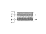
具体的には、繊維状導電性カーボンの抄紙体として、東レ社製のカーボンペーパー、TGP‐H030を用いたが、同等の特性を有するものであれば、使用可能である。なお、酸素極側は実施例1と同様の拡散層を用いた。図4は、本実施例のMEAの断面を示す図である。図4において15は浸み込み防止層、16は繊維状導電性カーボンの抄紙体、9は酸素極側の電極、17は燃料極側の電極である。評価条件は実施例1と同様とし、放電特性を測定した。 Specifically, carbon paper manufactured by Toray Industries, Inc., TGP-H030, was used as the paper body of fibrous conductive carbon, but any paper having the same characteristics can be used. In addition, the diffusion layer similar to Example 1 was used for the oxygen electrode side. FIG. 4 is a view showing a cross section of the MEA of the present embodiment. In FIG. 4, 15 is a penetration preventing layer, 16 is a fibrous conductive carbon papermaking body, 9 is an electrode on the oxygen electrode side, and 17 is an electrode on the fuel electrode side. The evaluation conditions were the same as in Example 1, and the discharge characteristics were measured.
比較に供するために、塗布法による一般的な方法でMEAを作製した。拡散層の形成方法は、ケッチェンブラックとPTFEディスパージョンをPTFEの混合比が固定分で20重量%となるように、混合、分散し、実施例6に用いた繊維状導電性カーボンの抄紙体の表面に、厚みが30μmとなるように、塗布、乾燥後、焼成するというものである。焼成条件や、MEAの作製方法は、実施例1と同様にした。 For comparison, an MEA was produced by a general method using a coating method. The diffusion layer was formed by mixing and dispersing Ketjen Black and PTFE dispersion so that the mixing ratio of PTFE was 20% by weight in a fixed portion, and the fibrous conductive carbon paper body used in Example 6 was used. Is applied, dried and then fired so that the thickness of the surface becomes 30 μm. The firing conditions and the MEA manufacturing method were the same as in Example 1.
図5は、比較例のMEAの断面を示す図である。図5において、18は塗布法によって形成した拡散層、19は酸素極側の電極、20は燃料極側の電極である。評価条件は実施例1と同様とし、放電特性を測定した。 FIG. 5 is a diagram showing a cross section of the MEA of the comparative example. In FIG. 5, 18 is a diffusion layer formed by a coating method, 19 is an electrode on the oxygen electrode side, and 20 is an electrode on the fuel electrode side. The evaluation conditions were the same as in Example 1, and the discharge characteristics were measured.
本発明は拡散層を改良することを目的としており、拡散の影響が大きく現れる電流密度の大きい範囲における、電流−電圧特性を測定した。表1は、実施例と比較例の電流−電圧特性をまとめて示したものである。また、図6は、実施例と比較例の、電流密度を25mA/cm2として、定電流放電したときの累積運転時間に対する電圧の変化を示す図である。 The object of the present invention is to improve the diffusion layer, and the current-voltage characteristics in the range where the current density where the influence of the diffusion greatly appears is large. Table 1 summarizes the current-voltage characteristics of the example and the comparative example. Moreover, FIG. 6 is a figure which shows the change of the voltage with respect to the accumulation operation time when constant current discharge is carried out with a current density of 25 mA / cm 2 in the example and the comparative example.

これらの結果を参照して、実施例1と比較例を比較すると、電流−電圧特性はほぼ同じであるが、累積運転時間に対する電圧の低下が実施例1の方が少なく、特性の向上が認められる。 By comparing these results with Example 1 and the comparative example, the current-voltage characteristics are almost the same, but the voltage drop with respect to the cumulative operation time is smaller in Example 1 and the improvement in characteristics is recognized. It is done.
また、実施例2及び実施例3と、実施例1及び比較例を比較すると、電流−電圧特性、累積運転時間に対する電圧の低下が、実施例2及び実施例3の方が少なく、特性の向上が認められる。これは、繊維状導電性カーボンを含む単位層を設けることにより、空孔率が増加し拡散性が向上したことと、繊維状導電性カーボンにより、強度が向上したためであると考えられる。 Further, when Example 2 and Example 3 are compared with Example 1 and Comparative Example, the voltage drop with respect to the current-voltage characteristics and the cumulative operation time is smaller in Examples 2 and 3 and the characteristics are improved. Is recognized. This is considered to be because by providing a unit layer containing fibrous conductive carbon, the porosity was increased and the diffusibility was improved, and the strength was improved by the fibrous conductive carbon.
実施例4及び実施例5を、実施例2及び実施例3と、それぞれ比較すると、電流−電圧特性、累積運転時間に対する電圧の低下が、やや少なくなっていることが認められる。本実施例では、疎水性高分子の種類、混合比の相違に起因すると考えられ、さらに検討を進めることにより特性向上が見込まれる。 When Example 4 and Example 5 are compared with Example 2 and Example 3, respectively, it is recognized that the voltage drop with respect to the current-voltage characteristics and the accumulated operation time is slightly reduced. In this example, it is considered that this is caused by the difference in the type and mixing ratio of the hydrophobic polymer, and further improvement of characteristics is expected by further study.
実施例6は、実施例1〜実施例5、比較例と比較して、電流−電圧特性において優れた結果を示し、拡散性が向上していることが認められる。これは、本実施例では燃料として、メタノール水溶液を用いているため、疎水性の拡散層を設けないことにより、燃料の拡散性が大きくなったためと考えられる。しかし、累積運転時間に対する電圧の低下は実施例1及び比較例と同程度の値を示した。 Example 6 shows excellent results in current-voltage characteristics as compared with Examples 1 to 5 and Comparative Example, and it is recognized that the diffusibility is improved. This is presumably because the diffusibility of the fuel was increased by not providing the hydrophobic diffusion layer because the methanol aqueous solution was used as the fuel in this example. However, the voltage drop with respect to the cumulative operation time showed the same value as in Example 1 and the comparative example.
実施例1〜実施例6のシート状の拡散層では、従来法のような電極基材にペーストを塗布して拡散層を形成する方式で発生していた、亀裂発生が見られなくなった。図7に実施例1、実施例2と比較例について、試料を各5個作製し、電流密度110mA/cm2で放電したときの電圧を測定した結果を示す。この図より拡散層をシート状にした実施例1、実施例2が比較例に比べ、ばらつきが少なく再現性が高いといえる。 In the sheet-like diffusion layers of Examples 1 to 6, the generation of cracks, which was generated by the method of applying the paste to the electrode substrate as in the conventional method to form the diffusion layer, was not observed. FIG. 7 shows the results of measuring the voltage when five samples were prepared and discharged at a current density of 110 mA / cm 2 for Example 1, Example 2, and Comparative Example. From this figure, it can be said that Example 1 and Example 2 in which the diffusion layer is formed into a sheet form have less variation and higher reproducibility than the comparative example.
以上に説明したように、本発明のシート状の拡散層を用いる方式により、従来法のような電極基材にペーストを塗布して拡散層を形成する方式に比較して、拡散層に亀裂発生がなく、均一な拡散層を再現良く得ることが出来た。また、従来の作製方法では実現が困難と考えられる多層構造の拡散層を1枚のシートに形成し、拡散特性、耐久性を向上させることができた。さらに、本発明のMEAでは、電極基材を用いないために、製造コストを低減でき、併せてこれを用いる固体高分子型燃料電池の特性向上、製造コスト低減にも寄与できる。 As described above, the method using the sheet-like diffusion layer of the present invention causes cracks in the diffusion layer compared to the conventional method of forming a diffusion layer by applying paste to an electrode substrate. And a uniform diffusion layer could be obtained with good reproducibility. In addition, a diffusion layer having a multilayer structure, which is considered difficult to realize by a conventional manufacturing method, was formed on a single sheet, and diffusion characteristics and durability could be improved. Furthermore, since the MEA of the present invention does not use an electrode base material, the manufacturing cost can be reduced, and at the same time, the characteristics of a polymer electrolyte fuel cell using the same can be improved and the manufacturing cost can be reduced.
1 電解質膜
2 触媒層
3,11 粒状の導電性カーボンを含む第1の単位層
4,12 繊維状の導電性カーボンを含む第2の単位層
5 繊維状の導電性カーボンを含む第3の単位層
6,8,13,18 拡散層
7,14,21 電極
9,19 酸素極側の電極
10,17,20 燃料極側の電極
15 浸み込み防止層
16 繊維状導電性カーボンの抄紙体
22 セパレータ
DESCRIPTION OF
Claims (7)
Priority Applications (1)
| Application Number | Priority Date | Filing Date | Title |
|---|---|---|---|
| JP2003331557A JP2005100748A (en) | 2003-09-24 | 2003-09-24 | Electrolyte membrane electrode bonded laminate, its manufacturing method as well as solid polymer fuel cell |
Applications Claiming Priority (1)
| Application Number | Priority Date | Filing Date | Title |
|---|---|---|---|
| JP2003331557A JP2005100748A (en) | 2003-09-24 | 2003-09-24 | Electrolyte membrane electrode bonded laminate, its manufacturing method as well as solid polymer fuel cell |
Publications (1)
| Publication Number | Publication Date |
|---|---|
| JP2005100748A true JP2005100748A (en) | 2005-04-14 |
Family
ID=34460184
Family Applications (1)
| Application Number | Title | Priority Date | Filing Date |
|---|---|---|---|
| JP2003331557A Pending JP2005100748A (en) | 2003-09-24 | 2003-09-24 | Electrolyte membrane electrode bonded laminate, its manufacturing method as well as solid polymer fuel cell |
Country Status (1)
| Country | Link |
|---|---|
| JP (1) | JP2005100748A (en) |
Cited By (10)
| Publication number | Priority date | Publication date | Assignee | Title |
|---|---|---|---|---|
| JP2006080083A (en) * | 2004-09-08 | 2006-03-23 | Samsung Sdi Co Ltd | Electrode for fuel cell, membrane-electrode assembly and fuel cell system |
| JP2007214102A (en) * | 2006-02-07 | 2007-08-23 | Samsung Sdi Co Ltd | Membrane electrode assembly, manufacturing method of membrane electrode assembly, and fuel cell |
| JP2007323939A (en) * | 2006-05-31 | 2007-12-13 | Sanyo Electric Co Ltd | Fuel cell |
| US8007957B2 (en) | 2004-11-26 | 2011-08-30 | Samsung Sdi Co., Ltd. | Electrode for fuel cell, fuel cell system comprising the same, and method for preparing the same |
| US8057958B2 (en) | 2005-07-29 | 2011-11-15 | Samsung Sdi Co., Ltd. | Electrode for fuel cell, membrane-electrode assembly comprising same and fuel cell system comprising same |
| JP2013152927A (en) * | 2011-12-26 | 2013-08-08 | Toray Ind Inc | Fuel cell gas diffusion layer, membrane electrode assembly and fuel cell |
| JP2014011163A (en) * | 2012-06-29 | 2014-01-20 | Jntc Co Ltd | Carbon substrate for gas diffusion layer, gas diffusion layer using the same, and electrode for fuel cell including the gas diffusion layer |
| US9346673B2 (en) | 2004-06-23 | 2016-05-24 | Samsung Sdi Co., Ltd. | Electrode for fuel cell, membrane-electrode assembly for fuel cell comprising the same, fuel cell system comprising the same, and method for preparing the electrode |
| JP2019200969A (en) * | 2018-05-18 | 2019-11-21 | 株式会社エフ・シー・シー | Fuel cell system |
| WO2023068335A1 (en) * | 2021-10-20 | 2023-04-27 | 凸版印刷株式会社 | Membrane electrode assembly and polymer electrolyte fuel cell |
Citations (8)
| Publication number | Priority date | Publication date | Assignee | Title |
|---|---|---|---|---|
| JPH07296818A (en) * | 1994-04-22 | 1995-11-10 | Japan Gore Tex Inc | Polymer solid electrolyte fuel cell electrode and joint of same with polymer solid electrolyte |
| JPH10261421A (en) * | 1997-03-17 | 1998-09-29 | Japan Gore Tex Inc | Gas diffusion layer material for high polymer solid electrolyte fuel cell and junction thereof |
| JP2000299113A (en) * | 1999-02-10 | 2000-10-24 | Toray Ind Inc | Conductive sheet and electrode base material for fuel cell using it |
| JP2001216973A (en) * | 2000-02-01 | 2001-08-10 | Toray Ind Inc | Electrode and its production as well as fuel cell using the same |
| JP2002124266A (en) * | 2000-10-17 | 2002-04-26 | Toyota Motor Corp | Fuel cell diffusion layer, its manufacturing method, and manufacturing device |
| JP2003036860A (en) * | 2001-07-19 | 2003-02-07 | Toray Ind Inc | Electrode backing and its manufacturing method and fuel cell using the same |
| JP2003173789A (en) * | 2001-09-28 | 2003-06-20 | Matsushita Electric Ind Co Ltd | Polymer electrolyte fuel cell |
| JP2003197202A (en) * | 2001-12-26 | 2003-07-11 | Hitachi Chem Co Ltd | Gas diffusion layer material for high polymer solid electrolyte fuel cell, and its junction |
-
2003
- 2003-09-24 JP JP2003331557A patent/JP2005100748A/en active Pending
Patent Citations (8)
| Publication number | Priority date | Publication date | Assignee | Title |
|---|---|---|---|---|
| JPH07296818A (en) * | 1994-04-22 | 1995-11-10 | Japan Gore Tex Inc | Polymer solid electrolyte fuel cell electrode and joint of same with polymer solid electrolyte |
| JPH10261421A (en) * | 1997-03-17 | 1998-09-29 | Japan Gore Tex Inc | Gas diffusion layer material for high polymer solid electrolyte fuel cell and junction thereof |
| JP2000299113A (en) * | 1999-02-10 | 2000-10-24 | Toray Ind Inc | Conductive sheet and electrode base material for fuel cell using it |
| JP2001216973A (en) * | 2000-02-01 | 2001-08-10 | Toray Ind Inc | Electrode and its production as well as fuel cell using the same |
| JP2002124266A (en) * | 2000-10-17 | 2002-04-26 | Toyota Motor Corp | Fuel cell diffusion layer, its manufacturing method, and manufacturing device |
| JP2003036860A (en) * | 2001-07-19 | 2003-02-07 | Toray Ind Inc | Electrode backing and its manufacturing method and fuel cell using the same |
| JP2003173789A (en) * | 2001-09-28 | 2003-06-20 | Matsushita Electric Ind Co Ltd | Polymer electrolyte fuel cell |
| JP2003197202A (en) * | 2001-12-26 | 2003-07-11 | Hitachi Chem Co Ltd | Gas diffusion layer material for high polymer solid electrolyte fuel cell, and its junction |
Cited By (12)
| Publication number | Priority date | Publication date | Assignee | Title |
|---|---|---|---|---|
| US9346673B2 (en) | 2004-06-23 | 2016-05-24 | Samsung Sdi Co., Ltd. | Electrode for fuel cell, membrane-electrode assembly for fuel cell comprising the same, fuel cell system comprising the same, and method for preparing the electrode |
| JP2006080083A (en) * | 2004-09-08 | 2006-03-23 | Samsung Sdi Co Ltd | Electrode for fuel cell, membrane-electrode assembly and fuel cell system |
| US8017284B2 (en) | 2004-09-08 | 2011-09-13 | Samsung Sdi Co., Ltd. | Electrode for a fuel cell, and a membrane-electrode assembly and fuel cell system comprising the same |
| US8007957B2 (en) | 2004-11-26 | 2011-08-30 | Samsung Sdi Co., Ltd. | Electrode for fuel cell, fuel cell system comprising the same, and method for preparing the same |
| US8057958B2 (en) | 2005-07-29 | 2011-11-15 | Samsung Sdi Co., Ltd. | Electrode for fuel cell, membrane-electrode assembly comprising same and fuel cell system comprising same |
| JP2007214102A (en) * | 2006-02-07 | 2007-08-23 | Samsung Sdi Co Ltd | Membrane electrode assembly, manufacturing method of membrane electrode assembly, and fuel cell |
| JP2007323939A (en) * | 2006-05-31 | 2007-12-13 | Sanyo Electric Co Ltd | Fuel cell |
| JP2013152927A (en) * | 2011-12-26 | 2013-08-08 | Toray Ind Inc | Fuel cell gas diffusion layer, membrane electrode assembly and fuel cell |
| JP2014011163A (en) * | 2012-06-29 | 2014-01-20 | Jntc Co Ltd | Carbon substrate for gas diffusion layer, gas diffusion layer using the same, and electrode for fuel cell including the gas diffusion layer |
| US9692070B2 (en) | 2012-06-29 | 2017-06-27 | Jntg Co., Ltd. | Carbon substrate for gas diffusion layer, gas diffusion layer using the same, and electrode for fuel cell, membrane-electrode assembly and fuel cell comprising the gas diffusion layer |
| JP2019200969A (en) * | 2018-05-18 | 2019-11-21 | 株式会社エフ・シー・シー | Fuel cell system |
| WO2023068335A1 (en) * | 2021-10-20 | 2023-04-27 | 凸版印刷株式会社 | Membrane electrode assembly and polymer electrolyte fuel cell |
Similar Documents
| Publication | Publication Date | Title |
|---|---|---|
| JP5107050B2 (en) | Manufacturing method of membrane electrode assembly for polymer electrolyte fuel cell | |
| JP5069927B2 (en) | Membrane electrode assembly for fuel cell and method for producing the same | |
| JP5004489B2 (en) | FUEL CELL CELL AND METHOD FOR PRODUCING THE SAME | |
| JP5066998B2 (en) | Membrane electrode assembly for polymer electrolyte fuel cells | |
| JP2008204945A (en) | Gas diffusion electrode substrate, gas diffusion electrode, its manufacturing method, and fuel cell | |
| JP2000299113A (en) | Conductive sheet and electrode base material for fuel cell using it | |
| WO2010090164A1 (en) | Porous electrode substrate, method for producing the same, membrane-electrode assembly, and solid polymer-type fuel cell | |
| US9601793B2 (en) | Electrolyte film—electrode assembly | |
| WO2012172989A1 (en) | Microporous layer sheet for fuel cells and method for producing same | |
| JP6717748B2 (en) | Gas diffusion base material | |
| JP5433147B2 (en) | Porous electrode substrate, method for producing the same, membrane-electrode assembly, and polymer electrolyte fuel cell | |
| JP2008311180A (en) | Membrane electrode assembly, its manufacturing method, and fuel cell using the membrane electrode assembly | |
| JP2006339018A (en) | Gas diffusion layer for fuel cell and its manufacturing method | |
| JP4959945B2 (en) | Polymer electrolyte fuel cell | |
| JP2010153222A (en) | Flexible type gas diffusion electrode substrate and membrane-electrode assembly | |
| JP2005100748A (en) | Electrolyte membrane electrode bonded laminate, its manufacturing method as well as solid polymer fuel cell | |
| JP2002358981A (en) | Current collector for fuel cell and its manufacturing method | |
| JP2010015908A (en) | Substrate for gas diffusion electrode and method for manufacturing the same, and membrane-electrode assembly | |
| JP4942362B2 (en) | Membrane-electrode assembly and polymer electrolyte fuel cell using the same | |
| JP2009087614A (en) | Diffusion layer of fuel cell, manufacturing method for diffusion layer of fuel cell, and fuel cell | |
| JP4781016B2 (en) | Manufacturing method of gas diffusion electrode for fuel cell | |
| JP5311538B2 (en) | Method for producing porous carbon electrode substrate | |
| JP2006351492A (en) | Gas diffusion layer for fuel cell, its manufacturing method and fuel cell using it | |
| JP2011049179A (en) | Membrane-electrode assembly for polymer electrolyte fuel cell and gas diffusion electrode substrate | |
| US11515542B2 (en) | Fuel battery |
Legal Events
| Date | Code | Title | Description |
|---|---|---|---|
| A977 | Report on retrieval |
Free format text: JAPANESE INTERMEDIATE CODE: A971007 Effective date: 20061117 |
|
| A131 | Notification of reasons for refusal |
Free format text: JAPANESE INTERMEDIATE CODE: A131 Effective date: 20061122 |
|
| A02 | Decision of refusal |
Free format text: JAPANESE INTERMEDIATE CODE: A02 Effective date: 20070319 |