JP2005073766A - Wheelchair and carry-in/out apparatus for wheelchair - Google Patents
Wheelchair and carry-in/out apparatus for wheelchair Download PDFInfo
- Publication number
- JP2005073766A JP2005073766A JP2003304993A JP2003304993A JP2005073766A JP 2005073766 A JP2005073766 A JP 2005073766A JP 2003304993 A JP2003304993 A JP 2003304993A JP 2003304993 A JP2003304993 A JP 2003304993A JP 2005073766 A JP2005073766 A JP 2005073766A
- Authority
- JP
- Japan
- Prior art keywords
- wheel
- wheelchair
- footrest
- use position
- vehicle
- Prior art date
- Legal status (The legal status is an assumption and is not a legal conclusion. Google has not performed a legal analysis and makes no representation as to the accuracy of the status listed.)
- Pending
Links
- 230000007246 mechanism Effects 0.000 claims abstract description 53
- 238000000034 method Methods 0.000 claims description 15
- 230000008569 process Effects 0.000 claims description 14
- 230000009191 jumping Effects 0.000 claims description 10
- 210000003127 knee Anatomy 0.000 claims description 4
- 230000003028 elevating effect Effects 0.000 description 13
- 230000009471 action Effects 0.000 description 4
- 238000005452 bending Methods 0.000 description 3
- 210000000078 claw Anatomy 0.000 description 3
- 239000000463 material Substances 0.000 description 3
- 230000002441 reversible effect Effects 0.000 description 3
- 239000000758 substrate Substances 0.000 description 3
- 238000010586 diagram Methods 0.000 description 2
- 238000006073 displacement reaction Methods 0.000 description 2
- 230000007257 malfunction Effects 0.000 description 2
- 238000013459 approach Methods 0.000 description 1
- 230000001174 ascending effect Effects 0.000 description 1
- 230000003111 delayed effect Effects 0.000 description 1
- 230000002452 interceptive effect Effects 0.000 description 1
- 238000012986 modification Methods 0.000 description 1
- 230000004048 modification Effects 0.000 description 1
- NJPPVKZQTLUDBO-UHFFFAOYSA-N novaluron Chemical compound C1=C(Cl)C(OC(F)(F)C(OC(F)(F)F)F)=CC=C1NC(=O)NC(=O)C1=C(F)C=CC=C1F NJPPVKZQTLUDBO-UHFFFAOYSA-N 0.000 description 1
- 230000000149 penetrating effect Effects 0.000 description 1
- 230000001105 regulatory effect Effects 0.000 description 1
- 230000003014 reinforcing effect Effects 0.000 description 1
Images

Landscapes
- Seats For Vehicles (AREA)
Abstract
Description
本発明は、車両に対して搬出入可能とされた車椅子及び車椅子の搬出入装置に関する。 The present invention relates to a wheelchair and a wheelchair loading / unloading device that can be loaded into and unloaded from a vehicle.
近年、お年寄りや体が不自由な人が車椅子ごと車両に乗り込んだり、あるいは車から車椅子ごと車外に退避出来るようにした搬出入装置(リフトアップ装置)付きの車両が提案されている。(特許文献1)
このものは、車両のフロアパネルにリフトアップ装置を備えており、車椅子を車外から車内に乗り込ませる場合には、車外において車椅子とリフトアップ装置を連結させた後に、リフトアップ装置を駆動させて車椅子の座席部を車体のフロアパネルの高さまで昇降させる。その後、車椅子を車両内に引き入れるスライド動作及び車内において回動動作を行い、車椅子を車内に格納するものである。
This is provided with a lift-up device on the floor panel of the vehicle, and when the wheelchair is put into the vehicle from outside the vehicle, after the wheelchair and the lift-up device are connected outside the vehicle, the lift-up device is driven to drive the wheelchair. The seat part is raised and lowered to the height of the floor panel of the car body. Thereafter, a slide operation for pulling the wheelchair into the vehicle and a rotation operation in the vehicle are performed, and the wheelchair is stored in the vehicle.
しかしながら、上記格納動作において、昇降動作を行った後車椅子をそのままの状態で車内に引き入れると、車椅子の前輪・後輪がドア開口部に干渉してしまう。そのため、車内への引き入れ動作に先立って、予め車椅子の前輪及び後輪の双方をそれぞれ折り畳む必要があり、煩わしさがあった。
本発明は上記のような事情に基づいて完成されたものであって、車両に対する搬出入動作を円滑に行うことが出来る車椅子、並びに車椅子の搬出入装置を提供することを目的とする。
However, when the wheelchair is pulled into the vehicle as it is after the lifting and lowering operation in the above-described storing operation, the front and rear wheels of the wheelchair interfere with the door opening. For this reason, it is necessary to fold both the front wheel and the rear wheel of the wheelchair in advance before the pulling operation into the vehicle, which is bothersome.
This invention is completed based on the above situations, Comprising: It aims at providing the wheelchair which can perform the carrying in / out operation | movement with respect to a vehicle smoothly, and the carrying in / out apparatus of a wheelchair.
上記の目的を達成するための手段として、請求項1の発明は、座席フレームの側方に左右一対の車輪を備えた車椅子と、車室内に設置されるとともに前記車椅子を支持可能な車椅子支持部を備え、当該車椅子支持部を駆動させることにより前記車椅子を車内と車外との間で出入りさせる駆動機構とからなる車椅子の搬出入装置であって、前記車輪は前記座席フレームに対して路面を走行可能な車輪使用位置とこの車輪使用位置より上方に跳ね上げられた車輪退避位置との間で変位可能に支持されるとともに、前記車椅子側には前記車輪を前記車輪使用位置にロック可能な車輪ロック部が設けられる一方、前記車体側或いは前記駆動機構側には前記車椅子の車内への搬入動作の過程で前記車輪ロック部に直接的あるいは間接的に係合して前記車輪のロックを解除する車輪ロック解除部が設けられ、更に、前記駆動機構或いは車両側のいずか一方、並びに前記車輪には、前記車輪ロックが解除された後に前記車椅子の車内への搬入動作の過程で互いに係合し、前記車輪を前記車輪使用位置から前記車輪退避位置に変位させる案内部が設けられた構成であるところに特徴を有する。 As means for achieving the above-mentioned object, the invention of claim 1 includes a wheelchair provided with a pair of left and right wheels on the side of a seat frame, and a wheelchair support portion that is installed in a passenger compartment and can support the wheelchair. A wheelchair loading / unloading device comprising a drive mechanism for driving the wheelchair support portion to move the wheelchair in and out of the vehicle, wherein the wheels travel on the road surface with respect to the seat frame. A wheel lock that is displaceably supported between a possible wheel use position and a wheel retracted position that is flipped up above the wheel use position, and that allows the wheelchair to lock the wheel to the wheel use position. On the other hand, the vehicle body side or the drive mechanism side is directly or indirectly engaged with the wheel lock portion in the process of carrying the wheelchair into the vehicle. A wheel unlocking portion for releasing the lock of the wheelchair is provided, and further, either the drive mechanism or the vehicle side, and the wheel are configured to perform an operation of carrying the wheelchair into the vehicle after the wheel lock is released. The present invention is characterized in that a guide portion is provided that engages with each other in the process and displaces the wheel from the wheel use position to the wheel retracted position.
請求項2の発明は、請求項1に記載のものにおいて、前記搬入動作が車外における車椅子の昇降動作及び、これに続く室内への引き込み動作によって行われるものにおいて、前記案内部は前記引き込み動作の過程において互いに係合し、前記車輪がドア開口部の下縁を通過する前の段階で前記車輪に対して前記車輪使用位置から前記退避位置への変位動作を行わせる構成であるところに特徴を有する。 According to a second aspect of the present invention, in the vehicle according to the first aspect, the carrying-in operation is performed by an ascending / descending operation of the wheelchair outside the vehicle and a subsequent retracting operation into the room. It is characterized in that it is configured to engage each other in the process and to cause the wheel to move from the wheel use position to the retracted position before the wheel passes the lower edge of the door opening. Have.
請求項3の発明は、請求項1または請求項2に記載のものにおいて、前記案内部は、前記搬出入装置側或いは前記車体側、又は前記車輪のいずれか一方側に設けられたカムフォロアと、他方側に設けられるとともに、前記カムフォロアと係合可能とされ、かつその軸線が前記車椅子の引き込み動作方向と交差し、車椅子が車内に搬入される際には前記車輪を前記車輪使用位置から前記車輪退避位置に跳ね上げ、車椅子が車外に搬出される際には前記車輪を前記車輪退避位置から前記車輪使用位置に復帰させる軌道を持ったカムとからなるところに特徴を有する。
The invention according to
請求項4の発明は、請求項1ないし請求項3のいずれかに記載のものにおいて、前記案内部は、左右の各車輪に対応してそれぞれ左右一対設けられた構成であるところに特徴を有する。
請求項5の発明は、請求項1ないし請求項4のいずれかに記載のものにおいて、前記車輪は前記座席フレームに対して車輪ホルダを介して取り付けられるとともに、この車輪ホルダは前記座席フレームに対して回動可能に取り付けられ、その回動動作によって前記車輪を前記車輪使用位置と前記車輪退避位置との間で変位させる構成であるところに特徴を有する。
According to a fourth aspect of the present invention, there is provided the apparatus according to any one of the first to third aspects, wherein the guide portion has a configuration in which a pair of left and right are provided corresponding to the left and right wheels, respectively. .
According to a fifth aspect of the present invention, in the vehicle according to any one of the first to fourth aspects, the wheel is attached to the seat frame via a wheel holder, and the wheel holder is attached to the seat frame. It is characterized in that it is configured to displace between the wheel use position and the wheel retracted position by the rotation operation.
請求項6の発明は、請求項1ないし請求項5のいずれかに記載のものにおいて、前記座席フレームの後部側には一対の後輪が設けられるとともに、前部側には前記車輪ホルダを備えた前輪及びフットレストが左右一対設けられるものにおいて、前記フットレストは前記座席フレームに対して使用者が足載せ可能なフットレスト使用位置と、このフットレスト使用位置より上方のフットレスト退避位置との間で変位可能に支持されるとともに、前記車輪ホルダには当該車輪ホルダの回動動作の過程で前記フットレストに当接して、前記フットレストを前記フットレスト使用位置から前記フットレスト退避位置に変位させる連係部が設けられた構成であるところに特徴を有する。 According to a sixth aspect of the present invention, in any one of the first to fifth aspects, a pair of rear wheels are provided on the rear side of the seat frame, and the wheel holder is provided on the front side. In the case where the front wheel and the footrest are provided in a pair on the left and right, the footrest can be displaced between a footrest use position where a user can place a foot on the seat frame and a footrest retract position above the footrest use position. In addition to being supported, the wheel holder is provided with a linking portion that contacts the footrest in the course of the rotation of the wheel holder and displaces the footrest from the footrest use position to the footrest retracted position. It has features in some places.
請求項7の発明は、請求項6に記載のものにおいて、前記フットレストは前記座席フレームに対して、前記フットレスト使用位置から前記フットレスト退避位置に至る際或いは前記フットレスト退避位置から前記フットレスト使用位置に至る際に、当該フットレストの足載せ面が車椅子に腰掛けた使用者の膝の持ち上げ方向に沿って進退するように支持された構成であるところに特徴を有する。 According to a seventh aspect of the present invention, in the sixth aspect of the present invention, when the footrest reaches the footrest retracted position from the footrest used position with respect to the seat frame or from the footrest retracted position to the footrest used position. In this case, the footrest surface of the footrest is characterized in that the footrest surface is supported so as to advance and retreat along the lifting direction of the knee of the user sitting on the wheelchair.
請求項8の発明は、前記座席フレームの後部側には後輪が左右一対設けられ、前部側には車輪ホルダ付きの前輪及びフットレストが左右一対設けられた車椅子であって、前記前輪及び前記フットレストは前記座席フレームに対して路面を走行可能な車輪使用位置とこの使用位置より上方に退避した車輪退避位置との間及び、使用者が足載せ可能なフットレスト使用位置とこのフットレスト使用位置より上方に退避したフットレスト退避位置との間で変位可能に支持されるとともに、前記前輪には、前記車輪使用位置から車輪退避位置への退避動作の過程で前記フットレストに当接して前記フットレストを前記フットレスト使用位置から前記フットレスト退避位置に変位させる連係部が設けられた構成であるところに特徴を有する。
The invention according to
<請求項1の発明>
請求項1の発明によれば、車椅子を車外から車内に搬入する搬入動作を行うと、車輪ロック解除部が車輪ホルダのロックを解除するとともに、案内部が車輪を車輪使用位置から車輪退避位置に自動的に変位させる。従って、使用者並びに介添え者等がわざわざ車輪格納のための作業を行う必要がなくなるため、使用性に優れる。
<Invention of Claim 1>
According to the invention of claim 1, when the carry-in operation for carrying the wheelchair into the vehicle from the outside of the vehicle is performed, the wheel lock release unit unlocks the wheel holder and the guide unit moves the wheel from the wheel use position to the wheel retracted position. Displace automatically. Therefore, it is not necessary for the user, the attendant, etc. to carry out the wheel storage work, so that the usability is excellent.
<請求項2の発明>
案内部による車輪の変位動作が、車輪がドア開口部を通過する前段階で行われるから、車輪とドア開口部との干渉が回避される。
<請求項3の発明>
請求項3の発明によれば、車輪使用位置から車輪退避位置或いは、車輪退避位置から車輪使用位置に至る一連の車輪の跳ね上げ及び復帰動作がカムフォロア及びカムにより案内されるから、車輪の跳ね上げ・復帰動作の確動が図られる。
<Invention of Claim 2>
Since the displacement operation of the wheel by the guide unit is performed before the wheel passes through the door opening, the interference between the wheel and the door opening is avoided.
<Invention of
According to the invention of
<請求項4の発明>
左右の車輪に跳ね上げ及び復帰動作を行わせる場合には、案内部を左右の車輪のいずれか一方に設けるとともに、他方側の車輪を案内部が設けられた側の車輪と連動(ロッド等で繋ぐ)させる手段が考えられる。しかし、仮に両車輪を連動させる場合には、車輪の動作時期が左右でズレると作動不良を起こす虞がある。この点に関し、請求項4の発明によれば、左右の車輪はそれぞれ案内部を備えており、各車輪が独立して動作可能な構成である。従って、仮に車椅子が搬出入装置に対して左右位置ずれした状態で連結されても、跳ね上げ動作及び復帰動作に支障をきたすことがない。
<Invention of Claim 4>
When the left and right wheels are flipped up and returned, the guide unit is provided on one of the left and right wheels, and the other wheel is linked to the wheel on the side where the guide unit is provided (with a rod or the like). A means to connect) is considered. However, if both wheels are interlocked, there is a risk of malfunction if the operation timing of the wheels deviates from side to side. In this regard, according to the invention of claim 4, the left and right wheels are each provided with a guide portion, and each wheel can operate independently. Therefore, even if the wheelchair is connected to the carry-in / out device in a state where it is displaced from side to side, it does not hinder the flip-up operation and the return operation.
<請求項5の発明>
請求項5の発明によれば、車輪の跳ね上げ・復帰動作は車輪ホルダの回動動作によって行われるから、車輪の跳ね上げ・復帰動作を例えば誘導溝に沿ったスライド動作により行う場合と比較して動作が円滑になる。
<請求項6・8の発明>
請求項4の発明によれば、車輪ホルダの回動動作(前輪に跳ね上げ動作)と連係してフットレストがフットレスト使用位置からフットレスト退避位置に自動的に変位するから、更に、使用性に優れる。
<Invention of Claim 5>
According to the fifth aspect of the present invention, the jumping / returning operation of the wheel is performed by the rotation operation of the wheel holder. Therefore, compared with the case where the jumping / returning operation of the wheel is performed by, for example, a sliding operation along the guide groove. Operation is smooth.
<Invention of
According to the invention of claim 4, since the footrest is automatically displaced from the footrest use position to the footrest retracting position in conjunction with the rotation operation of the wheel holder (the jumping operation to the front wheel), the usability is further improved.
<請求項7の発明>
車椅子を車室内に格納する搬入動作中にドア開口部との干渉を回避するためにフットレストに干渉回避動作(フットレスト使用位置からフットレスト退避位置への移動動作)を行わせる必要がある。請求項7の発明によれば、この干渉回避動作はフットレストの上動動作、すなわち足載せ面が使用者の膝の持ち上げ方向に沿ってなされるから、当該干渉回避動作中に使用者は膝を屈伸させるだけでよく、使用性に優れる。
<Invention of Claim 7>
It is necessary to cause the footrest to perform an interference avoiding operation (moving operation from the footrest use position to the footrest retracting position) in order to avoid interference with the door opening during the carry-in operation of storing the wheelchair in the passenger compartment. According to the seventh aspect of the present invention, since the interference avoiding operation is the upward movement of the footrest, i.e., the footrest surface is moved along the lifting direction of the user's knee, the user moves the knee during the interference avoiding operation. It only needs to bend and stretch, and it is excellent in usability.
本発明の実施形態を図1ないし図25によって説明する。
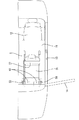
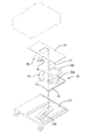
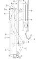
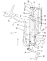
図1は本実施形態に適用された普通自動車の助手席側半分を示すものであって、車室内には助手席、及び後席シート12がフロアパネル11上に配置されている。助手席の側方にはドア開口部13が設けられており、そこにはヒンジを介してドア14が開閉可能に取付けられている。また、ドア開口部13の下縁にはスカッフ16が形成されている(図11参照)。
An embodiment of the present invention will be described with reference to FIGS.
FIG. 1 shows a passenger seat side half of an ordinary automobile applied to the present embodiment. A passenger seat and a
さて、助手席は車椅子Sに代わられており、フロアパネル11上には車椅子Sに対して次の動作を行わせる駆動機構Mを備えている。これら車椅子S、駆動機構Mによって本発明の搬出入装置が構成されている。
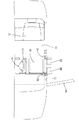
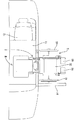
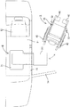
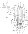
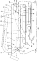
車椅子Sは、車室内において車体の進行方向を向いた前向位置(図1に示す位置)とドア開口部13側を向いた旋回位置(図2に示す位置)との間での回動動作、及び旋回位置から車外へ或いは車外から旋回位置への水平方向への引き込み・引き出し動作(図3参照)並びに車外での昇降動作がなされるようになっている。尚、以下の説明において、車椅子Sが車内から車外へ移動する一連の動作を搬出動作とし、車椅子が車外から車内へ移動する一連の動作を搬入動作とする。
Now, the front passenger seat is replaced with the wheelchair S, and on the
The wheelchair S rotates between a forward position (position shown in FIG. 1) facing the traveling direction of the vehicle body and a turning position (position shown in FIG. 2) facing the door opening 13 in the passenger compartment. In addition, a horizontal pull-in / draw-out operation from the turning position to the outside of the vehicle or from the outside of the vehicle to the turning position (see FIG. 3) and a lifting / lowering operation outside the vehicle are performed. In the following description, a series of operations in which the wheelchair S moves from the inside of the vehicle to the outside of the vehicle is referred to as a carry-out operation, and a series of operations in which the wheelchair moves from the outside of the vehicle to the inside of the vehicle is referred to as a carry-in operation.
まず、車椅子Sについて説明し、続いて駆動機構Mについて説明する。
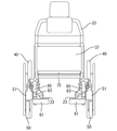
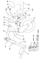
図5及び図6に示すように、車椅子Sは、断面がL字状をなして形成され車椅子Sの前後方向に伸びる左右一対の座席フレーム20を備えてなる。この座席フレーム20の上面側には座席フレーム20の長手方向に沿ってアッパーフレーム31が配されるともに、左右両座席フレーム20の後端同士が逆U字状をなすバックフレーム33によって架設されている。これらアッパーフレーム31間及びバックフレーム33間には、それぞれパッド材35、37が張られており使用者が着座可能となっている。また、座席フレーム20の後端部にはその上端部分が前方に屈曲されたアーム39が縦向きに取り付けられているが、これは着座者の肘掛けである。
First, the wheelchair S will be described, and then the drive mechanism M will be described.
As shown in FIGS. 5 and 6, the wheelchair S includes a pair of left and right seat frames 20 that are formed with an L-shaped cross section and extend in the front-rear direction of the wheelchair S. An
左右両座席フレーム20の外面の後部端には後輪取り付け用の軸孔21が同軸で穿設されている。一方、後輪40はその中央部分に軸孔21に対して遊嵌される支持ピン41を設けている。詳細には図示しないが、この支持ピン41の外面には球状をなすロック凸部がその一部を突出させる態様で埋めこまれている。このロック凸部は突出方向に付勢されており、支持ピン41の端部を軸孔21に対して差し込むと、ロック凸部が軸孔21に自動的に係合して後輪40を座席フレーム20に対して抜け止めするようになっている(回動動作は許容する)。
また、支持ピン41の外面側の軸端には解除部42が設けられており、そこを押圧操作すると前記ロック凸部の突出部分が支持ピン41の内部側に退避して軸孔21に対する係合を解いて後輪40を座席フレーム20より取り外すことが出来る。
A
Further, a
座席フレーム20の外面の前部側には車輪ホルダ51を備えた前輪50が配されている。車輪ホルダ51は、座席フレーム20に対して軸ピン53を介して回動自在に取り付けられるとともに、その回動動作によって当該前輪50を車輪使用位置(図20に示す位置)と、この車輪使用位置から前方へ跳ね上げられる車輪退避位置(図22に示す位置)との間で変位させるようになっいる。このように、前輪50を車輪使用位置から車輪退避位置に跳ね上げるのは車椅子Sを車内に搬入する際に、ドア開口部13のスカッフ16に対する干渉を回避するためである。
A
座席フレーム20の前部の内面側であって、下端寄りの位置には補強用のプレート29が取付られるとともに、その中央部分には、座席フレーム20を貫通する前輪ロック孔22が設けられている。一方、車輪ホルダ51外面の下部側であって、前輪ロック孔22と対向する位置には車輪ホルダ51を左右の壁面を架設するようにしてボス部51Cが形成されている(図23参照)。このボス部51Cは中空であって、内部には前輪ロックピン(本発明の車輪ロック部に相当する)55が進退可能に嵌め合わされている。この前輪ロックピン55は、ロックスプリング57によってロック方向(座席フレーム20側)に付勢されており、前輪50が車輪使用位置にあるときに前輪ロック孔22内に進入して前輪50を当該車輪使用位置にロックするようになっている。詳細には後述するが、前輪50のロック解除並びに前輪50の跳ね上げ・復帰動作(回動動作)は、車椅子Sの引き込み動作及び引き出し動作と連動してなされるようになっており、駆動機構Mと車椅子Sとの間にはこれら両動作を連動させるための連動機構150が設けられている。
A reinforcing
続いて、フットレスト60について説明する。座席フレーム20の前端部分には、円筒形のパイプ材65が縦向きに取り付けられるとともに、そこにはフットレスト60が支持されている。フットレスト60は平板状をなす足載せ板61と棒状をなすとともに前記パイプ材65に遊嵌され上端には抜止めピンを備えたロッド63とから構成されている。このフットレスト60も前輪50と同様に、フットレスト使用位置(図20に示す位置)とフットレスト退避位置(図22に示す位置)が設定されており車椅子Sの搬入動作の際に、スカッフ16との干渉を回避するようになっている。
Next, the
このフットレスト使用位置からフットレスト退避位置に至る持ち上げ動作はパイプ材65の軸線方向に沿ってなされるが、パイプ材65は座席フレーム20に対して縦向きに取り付けられてはいるものの垂直には配されておらず、やや斜めに取り付けられている。すなわち、フットレスト60の足載せ面が車椅子Sに腰掛けた使用者の膝の持ち上げ方向(屈伸方向)に沿ってなされるようになっており、持ち上げ動作中も、着座者は楽な姿勢に保たれる。
The lifting operation from the footrest use position to the footrest retracting position is performed along the axial direction of the
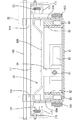
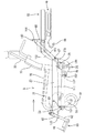
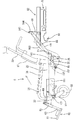
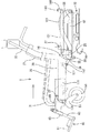
次に、駆動機構Mについて説明する。駆動機構Mは車椅子Sに回動動作を行わせる回動機構70と、昇降動作を行わせる昇降機構80と、引き出し・引き込み動作を行わせるスライド機構110とから構成されている。
図9に示すように、回動機構70はフロアパネル11に固定された取付け板71と、この取り付け板71に対して車両の前後方向にスライド可能に取り付けられた可動板72と、水平な板上をなす回動台座74とを設けており、可動板72の上面側にはインナリング72Aが、回動台座74の下面側にはアウタリング74Aがそれぞれ取付けられている。このインナリング72Aには、ボールベアリングを介してアウタリング74Aが回動可能に取付けられており、これにて、前記した車椅子Sがこの回動台座74と一体となって旋回する。
Next, the drive mechanism M will be described. The drive mechanism M includes a
As shown in FIG. 9, the rotating
回動台座74には回動用モータ75が設けられており、その回転軸にはピニオンギヤ76が取付けられている。一方、可動板72にはピニオンギヤ76と噛合するセクタギヤ73が設けられており、前記した回動用モータ75の駆動に伴って回動台座74が回動する。これにより、車椅子Sは車両の進行方向に向けた前向位置と、左方向を向いた旋回位置との間で正逆両方向に約90°の角度、回動される。
The
また、アウタリング74Aには誘導ピン77が設けられる一方、取り付け板71には前記誘導ピン77に対する誘導溝71Aが設けられており、回動用モータ75の駆動により回動台座74が回動すると、誘導ピン77と誘導溝71Aの案内作用により可動板72、ひいては回動台座74全体を車両の前後方向にスライドさせるようになっている。このように回動台座74に回転及びスライドの複合的な動作を取らせることで、車椅子Sに着座した使用者の足先と車体と間の回動動作中の隙間を広く確保するようにしている。
The
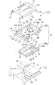
次に、昇降機構80について説明する。
本実施形態の昇降機構80は昇降スライド機構80Aとリンク機構80Bとから構成され、車外方向へのスライド動作と連動して昇降動作、すなわち車椅子Sを室内のフロアパネル11の高さから地面の高さまで下降或いは上昇させることが出来る。
まず、昇降スライド機構80Aについて説明する。図8に示すように、回動台座74の上面には、平板状をなすベースパネル81が取付けられている。このベースパネル81の左右両縁には車両の前後方向に沿って案内壁82が設けられている。この案内壁82はその前・後端同士を断面がコの字状をなす連結ブラケット83、84により架設されるとともに、その外面側には車外方向に開放する溝部82Aがその全長に亘って形成されている。
Next, the
The elevating
First, the
一方、スライダ88は、左右一対設けられた側部プレート88Aの上端同士を連結プレート88Bによって橋渡してなる。この両側部プレート88Aの内面側には案内壁82の溝部82Aに対して嵌合可能なガイドローラ89が前後一対取付けられている。このガイドローラ89が溝部82A内を転動することで、スライダ88が案内壁82に沿って移動する。
On the other hand, the
ベースパネル81上であって両案内壁82に挟まれた位置には、案内壁82に沿って前後送りねじ91が配されている。前後送りねじ91はその前端側が前側の連結ブラケット83に、後端側が後側の連結ブラケット84に軸支されている。一方、後側の連結ブラケット84はその一部に逃がし孔を設けており、そこには正逆双方向に回転可能とされた昇降スライドモータ92が前後に並んで一対配されている。これら両昇降スライドモータ92は前後送りねじ91に対してそれぞれ接続されている。このように、昇降スライドモータ92を複数個用いることで、モータを単数使用する場合に比べて径サイズの小さなモータを使用することが可能となる。これにより、モータを配置するのに必要な高さ方向のスペースを狭くすることが出来、装置全体の低背化を図っている。
A
一方、連結プレート88Bの下面の左右両側には前後送りねじ91に対して螺合するトラベルナット94がねじ止めされるようになっている。かくして、昇降スライドモータ92の駆動に伴って前後送りねじ91が軸回りに回転すると、スライダ88ひいては車椅子Sが案内壁82に沿ってスライドする。
On the other hand,
続いて、リンク機構80Bについて説明する。
スライダ88の前方には昇降フレーム95が配されている。昇降フレーム95はコの字状に形成されるとともに、昇降フレーム95の左右両側壁95Aには装着板97が架設されている。この装着板97には、後述するスライド機構110の駆動源が装着されている。また、側壁95Aの外面における上部の前後には一対の摺動ローラ99が回動可能に軸支されている。
Next, the
A
スライダ88と昇降フレーム95の間には上下リンクアーム101、103が架設されている。上部リンクアーム101は全長に亘って直線形状をなし、下部リンクアーム103は全体としては湾曲した形状をなす。両リンクアーム101、103の後端側は接続ピンによってスライダ88の側部プレート88Aにそれぞれ回動可能に軸支されている。一方、両リンクアーム101、103の前端部は昇降フレーム95の側壁95Aに接続ピンを介してそれぞれ回動可能に軸支されている。これらスライダ88、昇降フレーム95及び両リンクアーム101、103は四節リンクを構成しており、昇降フレーム95、ひいては車椅子Sをベースパネル81に対し平行に昇降させることが出来る。
案内壁82の前端側には支持ローラ85が軸支されている(図11参照)。この支持ローラ85は、前記した4節リンクと共にリンク機構80Bを構成し、4節リンクの回動動作の規制を行っている。具体的には、スライダ88がベースパネル81に対して最後端位置にあるとき(図11参照)には、左右の下部リンクアーム103の前端部の下縁が支持ローラ85に支持されており、4節リンクの回動動作が規制されている。一方、スライダ88が前進すると4節リンク全体が前進し、図12に示すように、下部リンクアーム103も支持ローラ85に対して前方へ変位し、下部リンクアーム103における支持ローラ85に対しする当接位置が直線状をなす前端部から湾曲部103Rへ移行する。これ以後は、スライダ88の前進に伴って4節リンクが回動し昇降フレーム95が次第に下降する。
A
また、下部リンクアーム103の前端部と支持ローラ85とが当接した状態において(図11の状態)、上部リンクアーム101が水平な姿勢となっている。これは、上部リンクアーム101が次述するスライド機構110の一部を構成しているためである。
Further, when the front end portion of the
スライド機構110の可動側となる車椅子支持台(本発明の車椅子支持部に相当する)111は図8に示すように、中央部が大きく開口した基板の左右両縁に下向きの側壁115を備えてなる。この両側壁115の内面側には車椅子Sの長さ方向に沿って、案内レール117が平行に取付けられている。この案内レール117は断面がコの字状をなしており、開放した側が向かい合うように配されている。この案内レール117の溝内であって、その前部には摺動ローラ99が嵌合するとともに、その後方には固定側となる上部リンクアーム101が収容されるようになっている(図10参照)。
As shown in FIG. 8, the wheelchair support base (corresponding to the wheelchair support portion of the present invention) 111 on the movable side of the
車椅子支持台111の下面側には案内レール117と平行にラック119が設けられている。一方、昇降フレーム95の装着板97の下面には進退用モータ120が装着されている。この進退用モータ120の回転軸にはラック119と噛合する進退ピニオン120Aが設けられている。そのため、進退用モータ120駆動させると、車椅子Sが案内レール117に沿って水平移動する。
なお、これら駆動機構Mはリモートコントローラにより駆動させることが出来る。
A
These drive mechanisms M can be driven by a remote controller.
次に車椅子Sを車椅子支持台111にロックするためのロック機構130について説明する。本実施形態においてロック機構130は車椅子Sの前側と後側の2箇所に設けられており、先に前側のロック機構130Aについて説明し、その後、後側のロック機構130Bについて説明する。
Next, the
これら両ロック機構130A、130Bはいずれも異なる機能を有する2つの機構部分から分割構成されており、一方は車椅子Sが昇降動作を行う際に車椅子Sの水平方向の移動を規制し、もう一方は車椅子Sが車内に取り込まれた時に、車椅子Sの上下動を規制することで車椅子Sを完全にロックする。
Both of these
図6に示すように、車椅子Sの左右の各座席フレーム20の内面の前端側にはコの字状をなすホルダ23Aを介してロックバー23が横向きに取付られている。一方、図8に示すように、車椅子支持台111の前端には第1のロックブラケット131が一対取付けられている。第1のロックブラケット131はL字状をなし折り曲げられた部分が前方を向くようにして配されるとともに、折り曲げられた先端部分には前記ロックバー23に対するロック溝135が形成されている。このロック溝135は、図11に示すように上向きに開放しており、そこよりロックバー23を溝内に受け入れるようになっている。ロックバー23がロック溝135内に収容された状態においては、ロック溝135とロックバー23の嵌め合いにより車椅子Sの水平方向の移動が規制されるようになっている(水平ロック機構)。
As shown in FIG. 6, a
また、第1のロックブラケット131は溝の前側の板幅に比べて溝の後側の板幅が広く形成されており折り曲げられた片の基端部分が強度アップされているが、これは、昇降動作の際に、第1のロックブラケット131によって車椅子Sの前端側を下支えするためである。また、ロック溝135の溝形状は前側が切り立って形成され、後側がなだらかに傾斜して形成されるが、これはロックバー23を溝内に案内するための誘いである。
Further, the
次に、昇降フレーム95の前端の左右両側には、第2のロックブラケット137が取付られている。この第2のロックブラケット137もL字状をなし折り曲げられた部分が前方を向くようにして配されている。この折り曲げられた先端部分は水平方向に伸びておりロック爪139を形成している。ロック爪139は幅方向に関してロック溝135より外側に位置するものの、その高さ寸法はロック溝135の開口部分の上縁の高さ寸法とほぼ等しく設定されており、図13に示すように、車椅子Sの引き込み動作が完了したときには、丁度ロック溝135の開口部分を閉止し、内部にロックバー23を閉じこめてロックバー23ひいては車椅子の上下動を規制するようになっている(上下ロック機構)。
Next,
続いて、後側のロック機構130Bについて説明する。
図8に示すように、車椅子支持台111の側壁外面の後端寄りの位置には係止ピン141が横向きに突出して取り付けられている。
一方、図19に示すように、車椅子Sの座席フレーム20外面の幅寸法は前端から後部寄りにかけてはほぼ同一幅(同幅部20A)で形成される一方、後端部分は幅が狭くなっており、丁度その境界部分には係止ピン141に対する係止溝25が形成されている。係止溝25は下方に開放しており、内部に係止ピン141を収容した状態においては係止溝25と係止ピン141の嵌め合いにより車椅子Sの水平方向の移動を規制するようになっている(水平ロック機構)。
Next, the
As shown in FIG. 8, a
On the other hand, as shown in FIG. 19, the width dimension of the outer surface of the
また、同幅部20Aの後端縁は係止ピン141のロック動作を案内する案内面26とされている。この案内面26には、係止ピン141が当接可能とされるとともに係止溝25と連続している。これら案内面26及び係止溝25は斜め上方へほぼ直線的に伸びるように形成されるが、この傾斜は、車椅子支持台111の昇降動作方向に沿った傾斜とされている。
尚、車椅子Sの水平方向の移動規制は、上述したように車椅子Sの前側及び後側の双方に設けられているが、そのロック動作のタイミングは次のようになっている。図14に示すように、車椅子Sを車椅子支持台111に向けて後退させてゆくと、やがて、係止ピン141が案内面26に当接する。この状態においては、車椅子Sの前側ではロック溝135の斜め上方にロックバー23が位置するとともに、車椅子Sの後側では係止ピン141の斜め上方に係止溝25が位置しており、いずれもロックがかかっていない。この状態から車椅子支持台111を上昇(斜め上方に移動)させると、係止ピン141は案内面26による案内作用を受けて係止溝25へと移動してゆき、係止ピン141が係止溝25に係合する。また、この係止タイミングとほぼ同じタイミングで、ロック溝135とロックバー23も係合するようになっている。
The rear end edge of the
In addition, although the movement restriction | limiting of the horizontal direction of the wheelchair S is provided in both the front side and the rear side of the wheelchair S as mentioned above, the timing of the lock operation | movement is as follows. As shown in FIG. 14, when the wheelchair S is moved backward toward the
次に、図10に示すように、スライダ88の後端の左右両側には一対の支持ブラケット144が取り付けられるとともに、この両支持ブラケット144間には係合バー143が横向きに架設されている。一方、図19に示すように、座席フレーム20の後端の中央部分には係合バー143に対する係合溝27が形成されている。係合溝27は後端側に開放するとともにその軸線がほぼ水平、すなわち車椅子支持台111の引き出し・引き込み動作方向に沿って形成されている。そして、車椅子Sの引き込み動作が完了した時には、内部に係合バー143を収容し係合溝27と係合バー143の嵌め合いにより車椅子Sの上下方向の移動を規制するようになっている(上下ロック機構)。
Next, as shown in FIG. 10, a pair of
また、係合溝27は後方に向かって末広がりに形成されるとともに、溝の下部27Aが上部側に比べて後方に延出している。
前側・後側のロック機構130はいずれも、溝とピンの嵌め合いを利用して車椅子Sの移動規制を行うものであって、そのロック動作及びロックの解除動作は、車椅子支持台111の昇降動作及び引き込み・引き出し動作と連動してなされるようになっている。
Further, the engaging
Both the front and
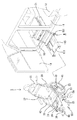
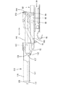
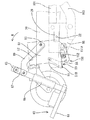
続いて、前輪50のロック解除並びに、前輪50の跳ね上げ・復帰動作を行わせる連動機構150について説明する。
図20に示すように、前記した車輪ホルダ51は前側から中央部寄りにかけてはほぼ同幅で形成されるが、後部の下部側は下方に張り出しており取付座51Bが形成されている。この取付座51Bの外面側には、揺動リンク59が横向きに配されている。この揺動リンク59の後端は、図23に示すように内向きに屈曲形成されており、そこは後に述べるカムフォロア(本発明の案内部及び車輪ロック解除部に相当する)142に対する押込み片部59Dとされている。また、揺動リンク59の基板部分に対する押込み片部59Dの屈曲角度は鈍角となっている。この揺動リンク59は取付座51Bと、この取付座51Bにねじ留めされるホルダプレートとの間に若干の遊びを設けた状態で挟持されており、揺動リンク59はその屈曲角度を維持したままの状態で頂点部分59Fを中心として揺動可能とされている。
Next, a description will be given of the
As shown in FIG. 20, the
揺動リンク59の基板の先端側には取付孔59Bが形成されている。この取付孔59Bは長孔に形成されるとともに、そこには前輪ロックピン55の一端が抜止めされた状態で嵌め合わされている。そのため、揺動リンク59は、常にはロックスプリング57による付勢を受け、図23に示すように、前輪ロックピン55と連結された側の一片が車輪ホルダ51の外面に密着し、押込み片部59Dは車輪ホルダ51の後端面から浮いた状態となっている。
A mounting
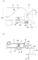
一方、昇降フレーム95の左右側壁95Aの外面の前端寄りの位置であって、揺動リンク59と丁度対面する高さ位置には、平板状をなす取付部151Aを有する支持ブラケット151が横向きに左右一対取り付けられている。これら各取付部151Aの前端の外面側にはカムフォロア152が取付られている。このように、揺動リンク59の引き込み方向前方にカムフォロア152が設けられることで、車椅子Sの引き込み動作の過程でカムフォロア152が揺動リンク59に当接し、これを揺動させることで前輪ロックピン55を進退させ前輪50のロックを解除させる。これが本発明の車内への搬入動作の過程で、車輪ロック解除部が車輪ロック部に間接的に係合(揺動リンク59を介して係合)して車輪のロックを解除する構成に相当する。
On the other hand, at a position near the front end of the outer surface of the left and
また、車輪ホルダ51の後端寄りの位置であって、取付座51Bの後側には下向きに開放するカム溝(本発明の案内部に相当する)56が形成されている。このカム溝56の前側の溝壁面と取付座51Bに配される揺動リンク59の外面は、図24の(A)に示すように揺動リンク59がカムフォロア152に押し込まれた状態にある時に、丁度面一となる設定とされている。そしてこの状態においては更に、カム溝56の回動方向前方にカムフォロア152が位置する設定とされている。そのため、カムフォロア152によって前輪50のロックが解かれ車輪ホルダ51が回動すると、カムフォロア152がカム溝56内に自動的に案内されるようになっている。
Further, a cam groove (corresponding to the guide portion of the present invention) 56 opened downward is formed at a position near the rear end of the
ところで、カム溝56はその軸線が車椅子Sの引き込み・引き出し方向に対しほぼ直角に交差するように伸びており、その軌道は車椅子Sの引き込み動作の過程(前輪50がスカッフ16を通過する前段階)で前輪50を車輪使用位置から車輪退避位置に跳ね上げる跳ね上げ軌道56Aと、車椅子Sの引き出し動作の過程(前輪50がスカッフ16を通過した後の段階)で前輪50を車輪退避位置から車輪使用位置に復帰させる復帰軌道56Bとを備えている(図20参照)。
このようにカム溝56及びカムフォロア152とからなる案内部は、車椅子Sの車内への搬入・搬出動作の過程で互いに係合し、前輪50を車輪使用位置から車輪退避位置へ、或いは車輪退避位置から車輪使用位置へ変位させるようになっている。
By the way, the
In this way, the guide portion composed of the
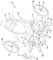
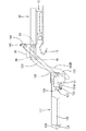
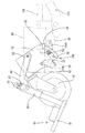
次に、前輪50の回動動作(車輪使用位置から車輪退避位置への跳ね上げ動作)に伴って、フットレスト60をフットレスト使用位置からフットレスト退避位置に変位させる機構について図20ないし図22を参照して説明する。
フットレスト60は第1・第2の連動リンク67、69を備えている。両連動リンク67、69はいずれも平板状をなす板材により形成され、その形状は第2の連動リンク69は全長が長く、への字状に屈曲して形成されるとともに、第1の連動リンク67は全長が短く、直線的な形状をなす。このうち、第1の連動リンク67の一端側はロッド63の上端部分に取り付けられるとともに、第2の連動リンク69の一端側は車輪ホルダ51の軸ピン53に取り付けられ、更に第1・第2の連動リンク67、69の他端同士が接続されている。
Next, referring to FIGS. 20 to 22, a mechanism for displacing the
The
一方、車輪ホルダ51の内面側(座席フレーム20側)には段差状をなす窪みが設けられており、そこは第2の連動リンク69に対する逃がし凹部51Aとされている。この逃がし凹部51Aの壁面には第2の連動リンク69に対する当接部(本発明の連係部に相当する)52が形成されている。この当接部52は、前輪50が跳ね上げ方向に回動された時には、第2の連動リンク69の下縁に当接することで、それ以降両連動リンク67、69を持ち上げてゆきフットレスト60をフットレスト使用位置からフットレスト退避位置に変位させるようになっている。
On the other hand, a step-shaped recess is provided on the inner surface side (the
また、前輪50及びフットレスト60が使用状態にあるときに、第2の連動リンク69と当接部52との間には隙間が設けられているが、このような設定とすることで、フットレスト60の変位動作が前輪50が回動動作に遅れて行われ、フットレスト60の使用状態が長く維持される。
In addition, when the
次に、車外から車内の助手席に車椅子Sごと乗り込む手順について説明する。 まず、同乗者が助手席側のドア14を開放するとともに、予め、車椅子支持台111を車外に突出・下降させておく(図5参照)。この状態から車椅子Sを後退させてゆき、車椅子支持台111に近づけてゆく。すると、座席フレーム20は車椅子支持台111の側壁115によって案内されながら、車椅子支持台111の上方に覆いかぶさってゆく。やがて、車椅子Sが車椅子支持台111にほぼ重なると、係止ピン141が座席フレーム20の案内面26に当接する(図14参照)。これにて、車椅子支持台111に対して車椅子Sが位置決めされる。尚、この状態においては、車椅子支持台111の前側に配されるロック溝135の斜め上方にはロックバー23が位置している。
Next, a procedure for getting into the passenger seat inside the vehicle together with the wheelchair S from outside the vehicle will be described. First, the passenger opens the
続いて、リモートコントローラを操作して、まず、昇降機構80を作動させる。すなわち、昇降スライドモータ92が駆動されると、前後送りねじ91に沿ってトラベルナット94が進退することで、スライダ88及び両リンクアーム101、103が復帰方向にスライドする。すると、支持ローラ85に下縁を支持された下部リンクアーム103が湾曲部103Rによって案内されてスライダ88側の支点を中心として回動する。これにて、リンク全体が回動し車椅子支持台111を上昇させる。
Subsequently, the remote controller is operated to first activate the
このように位置決めされた状態から車椅子支持台111の上昇動作がなされると、車椅子Sの前後に配される各水平ロック機構が自動的にロックするようになっている。具体的に説明すると、車椅子Sの後部側においては係止ピン141が案内面26に摺接しながらその傾斜に沿って上昇してゆき、やがて、係止溝25に進入して係止する。一方、車椅子Sの前部側においては、ロック溝135の昇降方向前方にロックバー23が位置しているから、車椅子支持台111の上昇に伴って、ロック溝135内にロックバー23が収容される。
このように車椅子Sの前部側においてはロック溝135とロックバー23とが係合し、車椅子Sの後部側においては係止ピン141と係止溝25とが係合することにより車椅子Sは車椅子支持台111によって下支えされ、かつ水平方向の移動が規制される。そのため、これ以降は、車椅子Sは車椅子支持台111と一体的に昇降動作を行う。
When the
In this way, the
また、昇降動作の途中で、着座者は適当な時期に後輪40のロック解除を行う。この場合において、着座者は後輪40の軸端に設けられた解除部42を押圧操作することにより後輪40と座席フレーム20の係止を解いて車椅子Sより後輪40を取り外すことが出来る。
In addition, the seated person unlocks the
車椅子Sが車体のフロアパネル11の高さに達すると、昇降スライドモータ92が停止する(昇降動作完了)。昇降スライドモータ92の停止と同時に進退用モータ120が駆動し、今度はスライド機構110によって車内への引き込み動作が開始される。すなわち、進退用モータ120が駆動することにより進退ピニオン120Aが回動するから、ラック119と進退ピニオン120Aの噛み合いにより車椅子支持台111、ひいては車椅子Sが上部リンクアーム101に沿ってスライドしつつ車内に引き込まれてゆく(図17参照)。
When the wheelchair S reaches the height of the
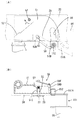
図23に示すように、この引き込み動作の進行に伴って揺動リンク59の押込み片部59Dは次第にカムフォロア152に近づいてゆき、やがてカムフォロア152は押込み片部59Dに干渉する。その後、カムフォロア152が押込み片部59Dをロック解除方向に押し込む。これにより、揺動リンク59がロックスプリング57のばね力に抗して揺動することで前輪ロックピン55が前輪ロック孔22から退避して、前輪50のロックが解除される。
As shown in FIG. 23, the pushing
前輪50のロックが解除されると、今度は前輪50の跳ね上げ方向への回動動作が開始される。具体的には、ロックが解除された後も、車輪ホルダ51は揺動リンク59を介してカムフォロア152によって押される。そのため、前輪50は軸ピン53を中心に図24に示すP方向、すなわち跳ね上げ方向に回動する。この回動動作により、カムフォロア152がカム溝56内に収容される。すると、カムフォロア152が今度がカム溝56の前側の溝壁を押圧するため、更に、車輪ホルダ51は回動を続け前輪50を跳ね上げてゆく。
When the lock of the
回動動作が進行すると、やがて、車輪ホルダ51の当接部52がフットレスト60の備える第2の連動リンク69の下縁に当接する。それ以降は、車輪ホルダ51が両連動リンク67、59を持ち上げるから、フットレスト60はフットレスト使用位置からフットレスト退避位置に変位される。
かくして、前輪50及びフットレスト60はいずれもスカッフ16を通過する前段階でスカッフ16より上方に退避する。これにより、車椅子Sは車体と干渉することなく、車内に引き込まれる。
As the turning operation proceeds, the
Thus, both the
そして、車椅子Sが旋回位置に至ると進退用モータ120は停止して、車内への引き込み動作が完了する。この状態において、前輪50及びフットレスト60は車輪あるいはフットレスト退避位置にある。また、車椅子Sの前側ではロック爪139がロック溝135の上部側に位置して、丁度ロック溝135の開口部分を閉止し内部にロックバー23を閉じこめるようになっている。これにより、車椅子Sの前側は水平方向及び上下方向の両方向に関して拘束、すなわち移動規制されることとなる。
When the wheelchair S reaches the turning position, the advancing / retreating
一方、車椅子Sの後部側においても、係合溝27内に係合バー143が進入する。これにより、既に係合状態にある係止溝25と係止ピン141に加えて、係合溝27と係合バー143も係合状態となるから、車椅子Sの後端側は前端側と同様に、水平方向及び上下方向の両方向に関して拘束、すなわち移動規制される。これにより、車椅子Sは車椅子支持台111に対して完全にロックされる。
On the other hand, the
その後、今度は回動用モータ75が駆動し、車椅子支持台111を旋回させる。この旋回動作の際、車椅子Sと車椅子支持台111のロック状態は保たれ、車椅子Sは車椅子支持台111と一体的に旋回する。旋回がほぼ90度なされ、車椅子Sが旋回位置から車体の前方を向いた前向位置に至ると、回動用モータ75が停止する。これにより、車椅子Sの搬入動作が完了する。
Then, this time, the
一方、車椅子Sを車内から車外に搬出する場合には、ほぼ上記と逆の手順を辿って、回動動作、引き出し動作、下降動作が順になされるとともに、スカッフ16を通過した後の引き出し動作の過程で、前輪50並びにフットレスト60は退避位置から使用位置に自動的に変位するようになっている。具体的に説明すると、車椅子Sの引き出し動作がなされると、今度は、カムフォロア152がカム溝56の後側の溝壁を押し込むため、図22に示すR方向、すなわち復帰方向に車輪ホルダ51が回動し、前輪50は車輪退避位置から車輪使用位置に自動的に復帰する。また、車輪ホルダ51の復帰方向への回動動作によって、当接部52が第2の連動リンク69から離間するから、フットレスト60は当接部52による支持を解かれて自重により下降してゆき、やがてフットレスト使用位置に至る。
On the other hand, when the wheelchair S is carried out from the inside of the vehicle, the rotation operation, the drawing operation, and the lowering operation are sequentially performed in the order reverse to the above, and the drawing operation after passing through the
このように、本実施形態によれば、車椅子Sを車外から車内に搬入する搬入動作を行うと、揺動リンク59が車輪ホルダ51のロックを解除するとともに、カム溝56及びカムフォロア152の案内作用によって、前輪50を車輪使用位置から車輪退避位置に自動的に変位させる。従って、使用者並びに介添え者等がわざわざ車輪格納のための作業を行う必要がなくなるため、使用性に優れる。また、車輪使用位置から車輪退避位置或いは、車輪退避位置から車輪使用位置に至る一連の前輪50の跳ね上げ及び復帰動作がカムフォロア152及びカム溝56により案内されるから、前輪50の跳ね上げ・復帰動作の確動が図られる。
Thus, according to the present embodiment, when the carry-in operation for carrying the wheelchair S into the vehicle from the outside of the vehicle is performed, the
更に、左右の前輪50の跳ね上げ及び復帰動作を行わせる場合には、カム溝56及びカムフォロア152を両前輪50のいずれか一方に設けるとともに、左右の前輪50を繋いで連動させる手段が考えられる。しかし、仮に両前輪50を連動させる場合には、前輪50の動作時期が左右でズレると作動不良を起こす虞がある。
この点に関し、本発明によれば、左右の前輪50はそれぞれカム溝56等を備えており、各前輪50が独立して動作可能な構成である。従って、仮に車椅子Sが車椅子支持台111に対して左右位置ずれした状態で連結されても、跳ね上げ動作及び復帰動作に支障をきたすことがない。
加えて、車輪ホルダ51の回動動作(前輪に跳ね上げ動作)と連係してフットレスト60がフットレスト使用位置からフットレスト退避位置に自動的に変位するから、更に、使用性に優れる。
Further, when the left and right
In this regard, according to the present invention, the left and right
In addition, since the
<他の実施形態>
本発明は上記記述及び図面によって説明した実施形態に限定されるものではなく、例えば次のような実施形態も本発明の技術的範囲に含まれ、さらに、下記以外にも要旨を逸脱しない範囲内で種々変更して実施することができる。
<Other embodiments>
The present invention is not limited to the embodiments described with reference to the above description and drawings. For example, the following embodiments are also included in the technical scope of the present invention, and further, within the scope not departing from the gist of the invention other than the following. Various modifications can be made.
(1)本実施形態によれば、前輪50を回動変位させる構成としたが、後輪40を回動変位させる構成としてもよい。
(1) According to the present embodiment, the
(2)本実施形態によれば、前輪50を復帰させるのに、カムフォロア152とカム溝56による案内作用を利用したが、例えば、バネ力等によって強制的に復帰させる形式のものであってもよい。
(2) According to the present embodiment, the guide action by the
S…車椅子
M…駆動機構
20…座席フレーム
50…前輪
55…前輪ロックピン(車輪ロック部)
56…カム溝(案内部)
59…揺動レバー
111…車椅子支持台(車椅子支持部)
152…カムフォロア(案内部、車輪ロック解除部)
S ... Wheelchair M ...
56 ... Cam groove (guide section)
59 ...
152. Cam follower (guide section, wheel lock release section)
Claims (8)
車室内に設置されるとともに前記車椅子を支持可能な車椅子支持部を備え、当該車椅子支持部を駆動させることにより前記車椅子を車内と車外との間で出入りさせる駆動機構とからなる車椅子の搬出入装置であって、
前記車輪は前記座席フレームに対して路面を走行可能な車輪使用位置とこの車輪使用位置より上方に跳ね上げられた車輪退避位置との間で変位可能に支持されるとともに、
前記車椅子側には前記車輪を前記車輪使用位置にロック可能な車輪ロック部が設けられる一方、前記車体側或いは前記駆動機構側には前記車椅子の車内への搬入動作の過程で前記車輪ロック部に直接的あるいは間接的に係合して前記車輪のロックを解除する車輪ロック解除部が設けられ、
更に、前記駆動機構或いは車両側のいずか一方、並びに前記車輪には、前記車輪ロックが解除された後に前記車椅子の車内への搬入動作の過程で互いに係合し、前記車輪を前記車輪使用位置から前記車輪退避位置に変位させる案内部が設けられた構成であることを特徴とする車椅子の搬出入装置。 A wheelchair with a pair of left and right wheels on the side of the seat frame;
A wheelchair loading / unloading device comprising a wheelchair support portion that is installed in a vehicle interior and capable of supporting the wheelchair and that drives the wheelchair support portion to drive the wheelchair in and out of the vehicle. Because
The wheel is supported so as to be displaceable between a wheel use position capable of traveling on the road surface with respect to the seat frame and a wheel retracted position that is flipped upward from the wheel use position.
On the wheelchair side, a wheel lock portion capable of locking the wheel at the wheel use position is provided, and on the vehicle body side or the drive mechanism side, the wheel lock portion is provided in the process of carrying the wheelchair into the vehicle. A wheel unlocking portion that unlocks the wheel by engaging directly or indirectly is provided,
Further, either the drive mechanism or the vehicle side, and the wheel are engaged with each other in the process of carrying the wheelchair into the vehicle after the wheel lock is released, and the wheel is used. A wheelchair loading / unloading device characterized in that a guide is provided to displace the wheel from the position to the wheel retracted position.
前記案内部は前記引き込み動作の過程において互いに係合し、前記車輪がドア開口部の下縁を通過する前の段階で前記車輪に対して前記車輪使用位置から前記退避位置への変位動作を行わせる構成であることを特徴とする請求項1記載の車椅子の搬出入装置。 In the case where the carry-in operation is performed by the lifting and lowering operation of the wheelchair outside the vehicle and the subsequent pulling operation into the room,
The guide portions engage with each other in the process of the pull-in operation, and the wheel is displaced from the wheel use position to the retracted position before the wheel passes the lower edge of the door opening. The wheelchair loading / unloading device according to claim 1, wherein the wheelchair loading / unloading device is provided.
前記搬出入装置側或いは前記車体側、又は前記車輪のいずれか一方側に設けられたカムフォロアと、
他方側に設けられるとともに、前記カムフォロアと係合可能とされ、かつその軸線が前記車椅子の引き込み動作方向と交差し、車椅子が車内に搬入される際には前記車輪を前記車輪使用位置から前記車輪退避位置に跳ね上げ、車椅子が車外に搬出される際には前記車輪を前記車輪退避位置から前記車輪使用位置に復帰させる軌道を持ったカムとからなることを特徴とする請求項1又は請求項2記載の車椅子の搬出入装置。 The guide part is
A cam follower provided on either the carry-in / out device side or the vehicle body side or the wheel;
The wheel is provided on the other side, engageable with the cam follower, and its axis intersects with the retracting direction of the wheelchair, and when the wheelchair is carried into the vehicle, the wheel is moved from the wheel use position to the wheel. 2. The cam according to claim 1, further comprising a cam having a trajectory for jumping up to a retracted position and returning the wheel from the wheel retracted position to the wheel use position when the wheelchair is carried out of the vehicle. The wheelchair loading / unloading device according to 2.
前記フットレストは前記座席フレームに対して使用者が足載せ可能なフットレスト使用位置と、このフットレスト使用位置より上方のフットレスト退避位置との間で変位可能に支持されるとともに、前記車輪ホルダには当該車輪ホルダの回動動作の過程で前記フットレストに当接して、前記フットレストを前記フットレスト使用位置から前記フットレスト退避位置に変位させる連係部が設けられた構成であることを特徴とする請求項1ないし請求項5に記載の車椅子の搬出入装置。 A pair of rear wheels are provided on the rear side of the seat frame, and a pair of left and right front wheels and footrests provided with the wheel holder are provided on the front side.
The footrest is supported so as to be displaceable between a footrest use position where a user can place a foot on the seat frame and a footrest retracting position above the footrest use position, and the wheel holder holds the wheel 2. The structure according to claim 1, further comprising a linkage portion that abuts on the footrest in the process of rotating the holder and displaces the footrest from the footrest use position to the footrest retracting position. 5. The wheelchair loading / unloading device according to 5.
前記前輪及び前記フットレストは前記座席フレームに対して路面を走行可能な車輪使用位置とこの使用位置より上方に退避した車輪退避位置との間及び、使用者が足載せ可能なフットレスト使用位置とこのフットレスト使用位置より上方に退避したフットレスト退避位置との間で変位可能に支持されるとともに、
前記前輪には、前記車輪使用位置から車輪退避位置への退避動作の過程で前記フットレストに当接して前記フットレストを前記フットレスト使用位置から前記フットレスト退避位置に変位させる連係部が設けられた構成であることを特徴とする車椅子。 A pair of left and right rear wheels are provided on the rear side of the seat frame, and a wheelchair is provided with a pair of left and right front wheels and a footrest with a wheel holder on the front side,
The front wheel and the footrest are located between a wheel use position where the vehicle can travel on the road surface with respect to the seat frame and a wheel retract position where the user retracts above the use position, and a footrest use position where the user can place a foot and the footrest. While being supported to be displaceable between the footrest retracted position retracted above the use position,
The front wheel is provided with a linkage portion that contacts the footrest during the retraction operation from the wheel use position to the wheel retraction position to displace the footrest from the footrest use position to the footrest retraction position. A wheelchair characterized by that.
Priority Applications (1)
| Application Number | Priority Date | Filing Date | Title |
|---|---|---|---|
| JP2003304993A JP2005073766A (en) | 2003-08-28 | 2003-08-28 | Wheelchair and carry-in/out apparatus for wheelchair |
Applications Claiming Priority (1)
| Application Number | Priority Date | Filing Date | Title |
|---|---|---|---|
| JP2003304993A JP2005073766A (en) | 2003-08-28 | 2003-08-28 | Wheelchair and carry-in/out apparatus for wheelchair |
Publications (1)
| Publication Number | Publication Date |
|---|---|
| JP2005073766A true JP2005073766A (en) | 2005-03-24 |
Family
ID=34408527
Family Applications (1)
| Application Number | Title | Priority Date | Filing Date |
|---|---|---|---|
| JP2003304993A Pending JP2005073766A (en) | 2003-08-28 | 2003-08-28 | Wheelchair and carry-in/out apparatus for wheelchair |
Country Status (1)
| Country | Link |
|---|---|
| JP (1) | JP2005073766A (en) |
Cited By (1)
| Publication number | Priority date | Publication date | Assignee | Title |
|---|---|---|---|---|
| CN117731495A (en) * | 2022-09-22 | 2024-03-22 | 丰田自动车株式会社 | Wheelchair fixing device |
-
2003
- 2003-08-28 JP JP2003304993A patent/JP2005073766A/en active Pending
Cited By (1)
| Publication number | Priority date | Publication date | Assignee | Title |
|---|---|---|---|---|
| CN117731495A (en) * | 2022-09-22 | 2024-03-22 | 丰田自动车株式会社 | Wheelchair fixing device |
Similar Documents
| Publication | Publication Date | Title |
|---|---|---|
| US6416272B1 (en) | Wheelchair with retractable wheels for conversion to vehicle passenger seat | |
| KR100515785B1 (en) | Vehicle seat | |
| CN111601732B (en) | Vehicle seat convenient to enter | |
| CN103562002B (en) | car seat | |
| WO1998043849A1 (en) | Vehicular rotary seat | |
| JP2006123905A (en) | Seat retractable into floor | |
| JP2004249818A (en) | Vehicle seat | |
| CN112092688A (en) | Seat assembly | |
| JP4099700B2 (en) | Vehicle lift-up seat | |
| JP2005073766A (en) | Wheelchair and carry-in/out apparatus for wheelchair | |
| JP4321183B2 (en) | Wheelchair loading / unloading device | |
| JP3239841B2 (en) | Rotation / slide interlocking mechanism in a rotating seat for vehicles | |
| JP2002119543A (en) | Seat lift elevating and lowering device for vehicle | |
| JP3042326B2 (en) | Lifting device for vehicle seat | |
| JP2002347488A (en) | Seat for vehicle | |
| JP2004148093A (en) | Car seat | |
| JP2005095248A (en) | Carry in and out apparatus for wheelchair | |
| JP4952399B2 (en) | Vehicle seat | |
| JP3755459B2 (en) | Vehicle seat | |
| JP3358534B2 (en) | Vehicle lift-up seat | |
| JPH0736833Y2 (en) | Vehicle lifter lock mechanism | |
| JP4907140B2 (en) | Seat lifting device | |
| JP4032294B2 (en) | Vehicle seat | |
| JP5003115B2 (en) | Vehicle seat | |
| JP2003291697A (en) | Elevating device for seat |
Legal Events
| Date | Code | Title | Description |
|---|---|---|---|
| A521 | Written amendment |
Free format text: JAPANESE INTERMEDIATE CODE: A523 Effective date: 20050131 |
|
| RD02 | Notification of acceptance of power of attorney |
Free format text: JAPANESE INTERMEDIATE CODE: A7422 Effective date: 20050302 |
|
| A621 | Written request for application examination |
Free format text: JAPANESE INTERMEDIATE CODE: A621 Effective date: 20060117 |
|
| RD04 | Notification of resignation of power of attorney |
Free format text: JAPANESE INTERMEDIATE CODE: A7424 Effective date: 20070821 |
|
| A131 | Notification of reasons for refusal |
Free format text: JAPANESE INTERMEDIATE CODE: A131 Effective date: 20090127 |
|
| A977 | Report on retrieval |
Free format text: JAPANESE INTERMEDIATE CODE: A971007 Effective date: 20090129 |
|
| A02 | Decision of refusal |
Free format text: JAPANESE INTERMEDIATE CODE: A02 Effective date: 20090602 |