JP2005073700A - Method and device for producing filter rod - Google Patents
Method and device for producing filter rod Download PDFInfo
- Publication number
- JP2005073700A JP2005073700A JP2004255483A JP2004255483A JP2005073700A JP 2005073700 A JP2005073700 A JP 2005073700A JP 2004255483 A JP2004255483 A JP 2004255483A JP 2004255483 A JP2004255483 A JP 2004255483A JP 2005073700 A JP2005073700 A JP 2005073700A
- Authority
- JP
- Japan
- Prior art keywords
- filter material
- type
- filter
- continuum
- nozzle
- Prior art date
- Legal status (The legal status is an assumption and is not a legal conclusion. Google has not performed a legal analysis and makes no representation as to the accuracy of the status listed.)
- Granted
Links
Images


Classifications
-
- A—HUMAN NECESSITIES
- A24—TOBACCO; CIGARS; CIGARETTES; SIMULATED SMOKING DEVICES; SMOKERS' REQUISITES
- A24D—CIGARS; CIGARETTES; TOBACCO SMOKE FILTERS; MOUTHPIECES OF CIGARS OR CIGARETTES; MANUFACTURE OF TOBACCO SMOKE FILTERS OR MOUTHPIECES
- A24D3/00—Tobacco smoke filters, e.g. filter tips or filtering inserts; Filters specially adapted for simulated smoking devices; Mouthpieces of cigars or cigarettes
- A24D3/02—Manufacture of tobacco smoke filters
- A24D3/0229—Filter rod forming processes
- A24D3/0237—Filter rod forming processes by extrusion
Landscapes
- Cigarettes, Filters, And Manufacturing Of Filters (AREA)
- Filtering Materials (AREA)
- Extrusion Moulding Of Plastics Or The Like (AREA)
- Processing And Handling Of Plastics And Other Materials For Molding In General (AREA)
Abstract
Description
本発明は、少なくとも1つのフィルタ材料を含む、たばこ加工産業のフィルタ連続体を製造するための方法と装置に関する。本発明は更に、フィルタ材料を載せることができる搬送要素と、フィルタ材料からフィルタ連続体を形成するための連続体形成装置とを備え、搬送要素が連続体形成装置に延びている、たばこ加工作業のフィルタ連続体を製造するための装置に関する。 The present invention relates to a method and apparatus for producing a filter continuum for the tobacco processing industry comprising at least one filter material. The invention further comprises a cigarette processing operation comprising a conveying element on which the filter material can be placed and a continuum forming device for forming a filter continuum from the filter material, the conveying element extending to the continuum forming device The present invention relates to an apparatus for producing a continuous filter body.
この方法と装置は例えば特許文献1によって知られている。たばこ煙フィルタを製造するための方法が記載されている。この場合、無端の糸状材料が噴射紡糸によって製造される。糸状材料は噴射経路に対して角度をなして配置された連続移動する受け取り面の方へ運ばれる。この場合、不規則的に配置された糸状区間の細長い帯状体が生じ、帯状体の一部が互いに相対的に側方に移動し、無端のフィルタ連続体が形成される。紡糸の後で、異なる添加剤を公知の方法で糸状材料に添加することができる。糸状材料として糸状酢酸セルロースまたはポリエチレンとポリプロピレンからなる糸が使用可能である。
本発明の課題は、高い品質を有する効果的なフィルタ連続体を製造することができる、冒頭に述べた方法と装置を提供することである。 The object of the present invention is to provide a method and apparatus as described at the outset, which can produce an effective filter continuum with high quality.
この課題は、少なくとも1つのフィルタ材料を含む、たばこ加工産業のフィルタ連続体を製造するための方法において、次の方法ステップ
少なくとも1つの第1の種類のフィルタ材料を溶融し、
少なくとも1つの第1の種類のフィルタ材料を少なくとも1個のノズルから押出し、
繊維の形をした少なくとも1つの第1の種類のフィルタ材料を搬送要素上に載せ、
搬送要素上のフィルタ材料を成形装置を通って搬送することによってフィルタ連続体を成形する
を有することによって解決される。
The object is to produce a filter continuum for the tobacco processing industry comprising at least one filter material, the following method steps melting at least one first type of filter material,
Extruding at least one first type of filter material from at least one nozzle;
Placing at least one first type of filter material in the form of a fiber on the conveying element;
The problem is solved by having the filter continuum formed by conveying the filter material on the conveying element through the forming device.
フィルタ材料を溶融または可塑化し、充分に軟らかくした後で、少なくとも1個のノズルから少なくとも1つの第1の種類のフィルタ材料を押し出すことにより、搬送要素上に放出される糸が生じる。これによって、ノズルから押し出される糸が適当に縮れる。ノズルからの押出しは噴射放出でもある。糸は搬送要素に至る途中で、好ましくは搬送要素上でまだ接着性を有するかまたはまだ可塑化されているので、糸の接触個所または交差個所で、糸が互いに付着または接着する。これによって、きわめて良好なフィルタ特性を有する高い品質の非常に効果的なフィルタ連続体が生じる。本発明の方法の特に有利な実施形では、少なくとも1つの第1の種類のフィルタ材料が圧縮空気によって少なくとも1個のノズルから押し出される。これによって、発生するフィルタ材料の縮れ効果が高められる。更に、少なくとも1つの第1の種類のフィルタ材料からなるフィルタ糸が搬送要素に載せられ、その後すぐにフィルタ材料が成形装置に搬送され、それによって方法パラメータを問題なく調節することができることにより、フィルタ連続体が効率的に製造される。これによって成形の際に付加的なエネルギーを少ししか必要としないかまたは全く必要としない。 After melting or plasticizing the filter material and making it sufficiently soft, extruding at least one first type of filter material from at least one nozzle results in a thread being released onto the conveying element. As a result, the yarn pushed out from the nozzle is appropriately shrunk. Extrusion from the nozzle is also jet discharge. On the way to the conveying element, the yarn is still adhesive or still plasticized on the conveying element, so that the yarn adheres or adheres to each other at the point of contact or crossing of the yarn. This results in a very effective filter continuum of high quality with very good filter properties. In a particularly advantageous embodiment of the method according to the invention, at least one first type of filter material is extruded from at least one nozzle by compressed air. Thereby, the shrinkage effect of the generated filter material is enhanced. Furthermore, the filter yarn comprising at least one first type of filter material is placed on the conveying element and immediately thereafter the filter material is conveyed to the forming device, whereby the process parameters can be adjusted without problems, so that the filter A continuum is produced efficiently. This requires little or no additional energy during molding.
ペレット、顆粒および/または粉末の形をした少なくとも1つの第2の種類のフィルタ材料が、少なくとも1個のノズルからの押出しに続いて、少なくとも1つの第1の種類のフィルタ材料に供給されると、フィルタ特性が大幅に改善される。第2の種類のフィルタ材料は例えば活性炭顆粒または活性炭粉末または活性炭ペレットである。勿論、味覚物質または他の添加物質を使用することができる。 When at least one second type of filter material in the form of pellets, granules and / or powder is fed to at least one first type of filter material following extrusion from at least one nozzle The filter characteristics are greatly improved. The second type of filter material is, for example, activated carbon granules or activated carbon powder or activated carbon pellets. Of course, taste substances or other additive substances can be used.
第1の種類のフィルタ材料が第2の種類のフィルタ材料を付着を可能にする時点で、少なくとも1つの第2の種類のフィルタ材料が少なくとも1つの第1の種類のフィルタ材料に供給されると、異なるフィルタ材料を確実に結合することができる。この場合特に、第1の種類のフィルタ材料がまだ搬送要素に衝突していない時点で、第2のフィルタ材料を第1のフィルタ材料に供給すると特に有利である。これによって、フィルタ材料がきわめて強く混合されるので、フィルタ連続体の品質、特に均一性が改善される。 When at least one second type of filter material is supplied to at least one first type of filter material at a time when the first type of filter material allows the second type of filter material to be deposited. , Different filter materials can be reliably combined. In this case, it is particularly advantageous to supply the second filter material to the first filter material when the first type of filter material has not yet hit the conveying element. This improves the quality of the filter continuum, in particular the uniformity, because the filter material is mixed very strongly.
少なくとも1つの第1の種類のフィルタ材料が、搬送要素に載せられた被覆材料帯上に載せられると、被覆材料帯を備えたフィルタ連続体をきわめて能率的に製造することができる。被覆材料帯は好ましくは多孔性であり、空気が通過可能である。搬送要素も好ましくは空気が通過可能である。従って、搬送要素と被覆材料帯を確実に結合するために、吸引空気がこの搬送要素と場合によっては被覆材料帯を通ってフィルタ材料に作用する。 When at least one first type of filter material is placed on the coating material strip placed on the conveying element, the filter continuum with the coating material strip can be produced very efficiently. The covering material strip is preferably porous and allows air to pass through. The conveying element is also preferably able to pass air. Thus, suction air acts on the filter material through this conveying element and possibly the coating material band in order to ensure a secure connection between the conveying element and the coating material band.
先ず最初に、少なくとも1つの第1の種類のフィルタ材料の層が載せられると、被覆材料帯を省略することができるかまたは最も外側の層に1つのフィルタ材料または1種類のフィルタ材料を有するフィルタ連続体またはフィルタを生じることができる。 First of all, when at least one layer of the first type of filter material is applied, the coating material band can be omitted or the filter having one filter material or one type of filter material in the outermost layer A continuum or filter can be produced.
続いて、例えば第1の種類のフィルタ材料と第2の種類のフィルタ材料からなる混合物のような他のフィルタ材料が層に載せられると、フィルタ特性を改善することができる。他のフィルタ材料の少なくとも一部が第2の種類のフィルタ材料を含んでいると、フィルタ特性が一層改善される。 Subsequently, the filter properties can be improved when other filter materials, such as a mixture of a first type of filter material and a second type of filter material, are placed on the layer. If at least a portion of the other filter material contains the second type of filter material, the filter characteristics are further improved.
載せられた層が他のフィルタ材料の被覆のために充分な幅を有すると、載せられる層を被覆材料と置き換え可能である。好ましくは、載せられた層が成形装置内で、他のフィルタ材料の周りに巻かれる。 If the deposited layer has a sufficient width for the coating of other filter materials, the deposited layer can be replaced with a coating material. Preferably, the deposited layer is wound around other filter materials in the molding apparatus.
続いて、少なくとも1つの第1の種類のフィルタ材料の層が載せられ、それによって他のフィルタ材料が層によってほぼ完全に被覆されると、少なくとも1つの第1の種類おフィルタ材料の層によって、他のフィルタ材料を異なるように被覆することができる。特に、成形装置内で層が互いに結合されるかあるいは層が他のフィルタ材料と結合される。これは好ましくは熱と圧力を加えることによって行われる。この圧力は成形によってフィルタ材料に作用する。 Subsequently, when the layer of at least one first type of filter material is applied, so that the other filter material is almost completely covered by the layer, the layer of at least one first type of filter material is Other filter materials can be coated differently. In particular, the layers are bonded together in the molding apparatus or the layers are bonded to other filter materials. This is preferably done by applying heat and pressure. This pressure acts on the filter material by molding.
少なくとも1つの第2の種類のフィルタ材料が好ましくは、少なくとも1個のノズルから搬送要素への途中で、少なくとも1個の第1の種類のフィルタ材料に供給される。その代わりに、第1の種類のフィルタ材料が搬送要素に載せられた後で、少なくとも1つの第2の種類のフィルタ材料が少なくとも1つの第1の種類のフィルタ材料に供給される。 At least one second type of filter material is preferably fed to the at least one first type of filter material on the way from the at least one nozzle to the conveying element. Instead, after the first type of filter material is placed on the transport element, at least one second type of filter material is supplied to the at least one first type of filter material.
第1および/または第2の種類のフィルタ材料が搬送要素の搬送方向に並んで幾つも載せられると、一種のフィルタ材料サンドイッチまたはフィルタ材料多重構造が生じる。 When several first and / or second types of filter material are placed side by side in the conveying direction of the conveying element, a kind of filter material sandwich or filter material multiple structure results.
第1の種類のフィルタ材料とは特に、たばこ加工産業またはたばこ加工産業の製品の包装において知られている酢酸セルロース、ポリエチレン、ポリプロピレン、ナイロン、ポリブタジエン(PBT)、ポリカーボネート(PC)、加熱硬化接着物質のようなフィルタ材料と、澱粉を有する混合物からなる生物分解性のポリマーであると理解される。 The first type of filter material is in particular cellulose acetate, polyethylene, polypropylene, nylon, polybutadiene (PBT), polycarbonate (PC), heat-curing adhesives known in the tobacco processing industry or packaging of products in the tobacco processing industry. And a biodegradable polymer consisting of a mixture having starch and a starch.
本発明の課題は更に、フィルタ材料を載せることができる搬送要素と、フィルタ材料からフィルタ連続体を形成するための連続体形成装置とを備え、搬送要素が連続体形成装置に延びている、たばこ加工作業のフィルタ連続体を製造するための装置において、少なくとも1個のノズルが設けられ、少なくとも1つの第1の種類の液化されたまたは可塑性を与えたフィルタ材料がノズルを通って搬送要素上にもたらされることによって解決される。 The subject of the invention is further a cigarette comprising a conveying element on which a filter material can be placed and a continuum forming device for forming a filter continuum from the filter material, the conveying element extending to the continuum forming device. In an apparatus for producing a filter continuum for processing operations, at least one nozzle is provided, and at least one first type of liquefied or plasticized filter material passes through the nozzle onto the conveying element. It is solved by being brought.
本発明による装置によって、きわめて良好なフィルタ特性と高い品質を有するフィルタ連続体を効率的に製造することができる。搬送要素とフィルタ材料の間に、被覆材料帯が配置されていると有利である。それぞれ1対のノズルが部分的に互いに向き合うように配置されていると、ノズルから出るフィルタ材料の糸の縮れと交差が高まる。複数のノズルが搬送要素の搬送方向に並べて設けられていると有利である。それによって、フィルタ材料からなる糸のきわめて良好な混合および交差が生じる。少なくとも1つの第2の種類のフィルタ材料のための少なくとも1個の供給装置が設けられていると、フィルタ特性を大幅に改善することができる。ノズルから出る、少なくとも1つの第1の種類のフィルタ材料の噴流に、第2の種類のフィルタ材料を供給するように、第2の種類のフィルタ材料が形成されていると有利である。れによって、第1と第2の種類のフィルタ材料の混合作用が高まる。連続体成形装置の少なくとも一部が加熱および/または冷却可能であると有利である。 The device according to the invention makes it possible to efficiently produce a filter continuum having very good filter properties and high quality. It is advantageous if a covering material strip is arranged between the conveying element and the filter material. If each pair of nozzles is positioned so that they are partially facing each other, the stringing and crossing of the filter material exiting the nozzles is increased. It is advantageous if a plurality of nozzles are arranged side by side in the transport direction of the transport element. This results in very good mixing and crossing of the yarns made of filter material. If at least one supply device for at least one second type of filter material is provided, the filter characteristics can be greatly improved. Advantageously, the second type of filter material is formed so as to supply the second type of filter material to the jet of at least one first type of filter material exiting the nozzle. This enhances the mixing action of the first and second types of filter materials. Advantageously, at least a part of the continuum forming device can be heated and / or cooled.
たばこ加工産業のフィルタ連続体を製造する上記方法を含む、紙巻きたばこ用フィルタを製造するための方法において、紙巻きたばこ用フィルタはフィルタ連続体から切断される。 In a method for producing a cigarette filter, including the above method of producing a filter continuum for the tobacco processing industry, the cigarette filter is cut from the filter continuum.
次に、本発明の全般的な思想を制限することなく、実施の形態に基づいて本発明を詳しく説明する。明細書で詳しく説明していない本発明のすべての特徴については、図が参照される。 Next, the present invention will be described in detail based on embodiments without limiting the general idea of the present invention. For all features of the invention not described in detail in the specification, reference is made to the figures.
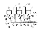
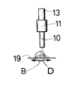
図1は、本発明による連続体形成機械、すなわちたばこ加工産業のフィルタ連続体を製造するための装置の一部を概略的に示す正面図である。例えばホットメルト接着物質貯蔵容器11とも呼ばれる加熱硬化接着物質(高温にかわ)貯蔵容器11のような貯蔵タンクから、ノズル10を経て、加熱硬化接着物質が圧力下で排出され、被覆材料17または成形帯状体19に供給される。たばこ加工産業またはたばこ製品の包装産業で知られているホットメルト接着物質または加熱硬化接着物質の代わりに、ポリプロピレン、ポリエチレン、酢酸セルロース、ビスフェノールA−炭酸−エステルをベースとした炭酸プロピレンまたはポリカーボネート、ナイロンおよび澱粉を有する混合物からなる生物分解性のポリマーのような他の材料を使用することができる。この材料、図1の実施の形態では加熱硬化接着物質14またはホットメルト接着物質または他の例として澱粉を有する混合物からなる生物分解性のポリマーまたは上記の材料は、ノズル10から出た後で、糸の形をしている。この糸は充分な圧力によって適当に縮れて被覆材料17または成形帯状体19に載せられる。
FIG. 1 is a front view schematically showing a part of an apparatus for producing a continuum forming machine according to the invention, ie a filter continuum for the tobacco processing industry. For example, from a storage tank such as a hot-melt adhesive
フィルタ特性を改善するために、顆粒15が顆粒貯蔵容器13から供給管12を経て繊維状加熱硬化接着物質14または糸状加熱硬化接着物質14に供給される。これによって、加熱硬化接着物質14と顆粒15の両フィルタ材料のきわめて良好な混合物が生じる。ノズル10から出る繊維状体または糸状体は、被覆材料17または成形帯状体19に至る途中でまだ接着性または付着性を有するので、他のフィルタ材料、すなわち例えば顆粒15と他の糸状体は互いに接着されるかまたは互いに付着する。これによって、フィルタ材料の確実な結合が生じる。図1の実施の形態では3個のノズル10と2個の供給管12が設けられているので、充分な量のフィルタ材料が被覆材料帯17または成形帯状体19に塗布される。これによって、高い製造速度が達成される。成形帯状体19は図1に示していない成形支持体の方へ搬送方向18に移動する。
In order to improve the filter characteristics, the
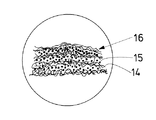
図2はA−A線に沿った概略断面図である。この断面図には、被覆材料17または成形帯状体19の形状が一層正確に示してある。被覆材料17を使用する際、被覆材料は成形帯状体19上にそれ自体公知の方法で載せられる。図3には混合物16が拡大して示してある。顆粒15と、縮れた糸状加熱硬化接着物質14が見える。
FIG. 2 is a schematic cross-sectional view along the line AA. In this cross-sectional view, the shape of the covering material 17 or the shaped
図4〜6は、本発明による連続体形成機械の一部の他の実施の形態を示している。この実施の形態では、成形帯状体19が平らに形成され、しかもフィルタ材料が載せられている間は平らに形成されている。搬送方向下流において初めて、フィルタ連続体を形成するために、成形帯状体が成形装置で成形される。図4〜6の実施の形態では、糸状加熱硬化接着物質14と顆粒15が交互に載せられる。この場合、外側の層は糸状加熱硬化接着物質からなっている。これにより、一種のサンドイッチ構造が生じる。糸状加熱硬化接着物質からなる第1の層は幅Bにわたって載せられる。幅Bは、載せられた他の全フィルタ材料のまわりに巻付けるために充分である。幅Bは少なくとも2πrである。ここで、rは製造すべきフィルタ連続体の半径である。
4-6 show another embodiment of a portion of a continuum forming machine according to the present invention. In this embodiment, the molded
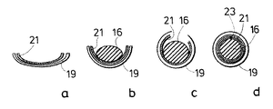
何らかの方法で連続的に行われるフィルタ材料の載置が図7a)〜d)に示してある。先ず最初に、繊維状加熱硬化接着物質14からなる繊維フリースの形をした層21が成形帯状体19上に載せられる。この層の載置の間、吸引空気が成形帯状体19の範囲全体を通過するので、繊維フリース21を形成する糸状加熱硬化接着物質14が成形帯状体19に保持される。繊維フリース21を形成した後で、糸状加熱硬化接着物質14と顆粒15からなる混合物が繊維フリース21内または繊維フリース上に形成される。ここで、成形帯状体19の中央部分だけに吸引空気が作用させられるので、混合物16が一部範囲にのみたまる。続いて、フィルタ材料が成形帯状体19によって成形装置に運ばれる。この成形装置では、繊維フリース21と成形帯状体19が混合物16の周りに巻かれる。続いて、繊維フリース21を混合物16の周りに完全に巻いた後で、繊維フリースが継目23で加熱によって連結され、それによって繊維フリース21が閉じる。
The placement of the filter material, which is carried out continuously in some way, is shown in FIGS. 7a) -d). First of all, a
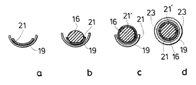
他の実施の形態が図8a)〜d)に示してある。この場合、混合物の被覆は2つのフリース21,21′によって行われる。先ず最初に、一方の繊維フリース21が形成され、そして混合物16が繊維フリース21内に運ばれ、続いて繊維フリース21′の形をした一種のカバーが混合物上に被覆される。図示していない成形装置で、両継目個所23が熱の作用によって互いに連結される。
Another embodiment is shown in FIGS. 8a) -d). In this case, the coating of the mixture is performed by two
これらの実施の形態(図6〜8)で形成される繊維連続体は、顆粒の割合を非常に高くすることができる。更に、形成された繊維連続体を切断することによって形成されるフィルタ要素は、図6〜8の実施の形態では、別個の被覆材料なしでもよい。顆粒は繊維によって保持される。 The fiber continuum formed in these embodiments (FIGS. 6 to 8) can have a very high proportion of granules. Further, the filter element formed by cutting the formed fiber continuum may be without a separate coating material in the embodiment of FIGS. The granules are retained by the fibers.
スピナレットヘッド27(図9または13)のノズルまたはスピナレットによって、糸または繊維が形成される。有利に使用されるスピナレットヘッド27は、ノルドソン(Nordson)社のサミットシステム(Summit System)である。
A thread or fiber is formed by the nozzle or spinneret of the spinneret head 27 (FIG. 9 or 13). The
顆粒供給部12から、顆粒が繊維と共に、吸引帯状体として形成可能な成形帯状体19上に吹き出されので、顆粒と、熱可塑性材料のまだやや接着する紡糸とが連結される。この場合、成形帯状体19は連続体形成装置22,22′(図9または13)の方へ移動する。連続体形成装置では、連続体の形状を塑性的に決定するために、連続体が先ず最初に加熱され、そして冷却される。これにより、被覆紙または被覆材料17を省略することができる。顆粒/繊維を供給した後で、もう一度純粋な繊維層を被覆することができる。これによって、棒の全周が繊維層で被覆される。
Since the granules are blown from the
図7d,8dに概略的に示した棒成形は好ましくは、加熱とそれに続く冷却によって行われる。材料は一部を既に示したように、PP,PE,PBT,ナイロン,PC,CA,加熱硬化接着物質のようなすべての樹脂およびポリマーと、澱粉を有する混合物からなる生物分解性のポリマーである。材料に関しては欧州特許第861036号公報の内容全体が参照される。上記のすべての材料は本特許出願の開示内容に収容すべきである。混合物16は好ましくは80〜95重量%の活性炭顆粒または活性炭粉末または活性炭ペレットと、5〜20重量%の熱可塑性材料(樹脂またはポリマー)の1つまたは複数の種類の繊維を含んでいる。ペレットまたは顆粒または粉末は好ましくは50μmから4mmの大きさである。ノズル10から出る繊維は有端であってもよいし、無端であってもよい。上記の材料からなる純粋な繊維フィルタを製造することもできる。これは1種類の繊維からなっていてもよいし、異なる種類の繊維からなっていてもよい。
The rod forming shown schematically in FIGS. 7d and 8d is preferably performed by heating followed by cooling. The material is a biodegradable polymer consisting of a mixture of all resins and polymers such as PP, PE, PBT, nylon, PC, CA, heat-curing adhesives and starch, as already shown in part. . Regarding the material, reference is made in its entirety to EP 861036. All the above materials should be included in the disclosure of this patent application.
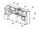
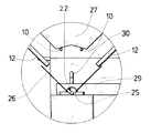
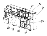
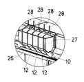
図9は本発明による連続体形成機械24の概略的な斜視図である。スピナレットヘッド27は例えば図11,12に示すように、複数のノズルを有する。複数のノズルは搬送方向18に並べて配置することができる。加熱硬化接着物質14が加熱され、ノズルを通ってホッパー26内に搬送され、成形帯状体19または成形帯状体19上に配置された被覆材料17上に供給される。この場合、成形帯状体19はホッパー26の下側の範囲においてガイド25内を案内される(図12参照)。搬送方向に見てスピナレットヘッド27の中央範囲において、2個の顆粒供給部28が設けられている。この顆粒供給部は供給管12に達している。それによって、顆粒またはペレットまたは粉末は、成形帯状体19上の繊維状加熱硬化接着物質に供給される。フィルタ材料の供給に続いて、成形部22,22′が設けられている。この成形部では、先ず最初に、加熱部分22でフィルタ連続体が成形される。それによって、続いて、成形部22′の冷却部分においてフィルタ連続体を硬化させることができる。
FIG. 9 is a schematic perspective view of a
図10は図9の一部の拡大図である。 FIG. 10 is an enlarged view of a part of FIG.
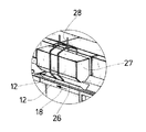
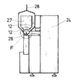
図11は図9の概略的な側面図である。この場合、ノズル10と連続体形成範囲がはっきり見える。この連続体形成範囲は、図11の拡大図である図12に最も明瞭に示してある。図12には更に、取っ手30を備えた成形カバー29が正確に示してある。図示していないフィルタ連続体を案内する成形部22は図12にも示してある。
FIG. 11 is a schematic side view of FIG. In this case, the
図13は本発明による連続体形成機械24の他の実施の形態を示している。この場合、複数の顆粒供給部28、本実施の形態では5個の顆粒供給部が設けられている。従って、顆粒と繊維状加熱硬化接着物質または他の熱可塑性材料からなる繊維が良好に混合される。この実施の形態(図13.14)では、ボビン31によって示した包被材料すなわち被覆材料17が使用される。図13に示したこの実施の形態では、成形部は加熱部分22と冷却部分22′を分離して形成されている。
FIG. 13 shows another embodiment of the
図14は、詳細に示すために図13の一部を拡大して示している。 FIG. 14 shows a part of FIG. 13 in an enlarged manner for the sake of detail.
本発明による方法と本発明による装置の重要な利点は、繊維と顆粒の、接着剤なしの結合または繊維自体の、接着剤なしの結合にある。繊維と比べて、きわめて多量の顆粒を使用することができる。更に、製造された繊維またはフィラメントの直径は、スピナレットヘッド27のノズル10またはスピナレットを交換するだけで変更可能である。繊維特性を改善するために、ポリマーを混合することができる。更に、在庫管理が簡単である。なぜなら、繊維をバレンの形態でなく顆粒の形態で貯蔵することができ、それによって貯蔵時の必要スペースが狭くて済むからである。
An important advantage of the method according to the invention and the device according to the invention lies in the bonding of the fibers and granules without adhesive or the bonding of the fibers themselves without adhesive. Very large amounts of granules can be used compared to fibers. Furthermore, the diameter of the manufactured fiber or filament can be changed by simply changing the
温度と搬送速度は好ましくは、フィルタ連続体をフィルタ棒に切断するために設けられたカッターの個所で、繊維連続体が充分に冷却されるように調節される。更に、高い連続体速度も可能である。更に、例えばフレーバーと充填材等のような他の材料を、フィルタ連続体に簡単に添加することができる。更に、きわめて有利な実施の形態では、別個の被覆材料が不要である。 The temperature and conveying speed are preferably adjusted so that the fiber continuum is sufficiently cooled at the location of the cutter provided to cut the filter continuum into filter rods. Furthermore, high continuum speeds are possible. In addition, other materials such as flavors and fillers can be easily added to the filter continuum. Furthermore, in a very advantageous embodiment, no separate coating material is required.
10 ノズル
11 加熱硬化接着物質
12 供給管
13 顆粒貯蔵装置
14 加熱硬化接着物質
15 顆粒
16 混合物
17 被覆材料
18 搬送方向
19 成形帯状体
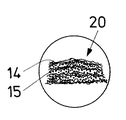
20 フィルタ材料サンドイッチ
21,21′ 繊維フリース
22 成形部、加熱部分
22′ 成形部、冷却部分
23 継目
24 連続体形成機械
25 ガイド
26 ホッパー
27 スピナレット
28 顆粒供給部
29 成形カバー
30 取っ手
31 ボビン
B 幅
DESCRIPTION OF
Claims (22)
少なくとも1つの第1の種類のフィルタ材料(14)を溶融し、
少なくとも1つの第1の種類のフィルタ材料(14)を少なくとも1個のノズル(10)から押出し、
繊維の形をした少なくとも1つの第1の種類のフィルタ材料(14)を搬送要素(19)上に載せ、
搬送要素(19)上のフィルタ材料(14,15)を成形装置(22,22′)を通って搬送することによってフィルタ連続体を成形する
を有することを特徴とする方法。 In a method for producing a filter continuum of the tobacco processing industry comprising at least one filter material (14, 15), the following method steps melting at least one first type of filter material (14),
Extruding at least one first type of filter material (14) from at least one nozzle (10);
At least one first type of filter material (14) in the form of fibers is placed on the conveying element (19),
A method comprising forming a filter continuum by conveying filter material (14, 15) on a conveying element (19) through a forming device (22, 22 ').
Applications Claiming Priority (1)
| Application Number | Priority Date | Filing Date | Title |
|---|---|---|---|
| EP03019976 | 2003-09-03 |
Publications (2)
| Publication Number | Publication Date |
|---|---|
| JP2005073700A true JP2005073700A (en) | 2005-03-24 |
| JP4512453B2 JP4512453B2 (en) | 2010-07-28 |
Family
ID=34203228
Family Applications (1)
| Application Number | Title | Priority Date | Filing Date |
|---|---|---|---|
| JP2004255483A Expired - Fee Related JP4512453B2 (en) | 2003-09-03 | 2004-09-02 | Method and apparatus for producing filter continuum |
Country Status (5)
| Country | Link |
|---|---|
| US (1) | US7300394B2 (en) |
| JP (1) | JP4512453B2 (en) |
| CN (1) | CN1589688B (en) |
| AT (1) | ATE361004T1 (en) |
| DE (1) | DE502004003664D1 (en) |
Families Citing this family (25)
| Publication number | Priority date | Publication date | Assignee | Title |
|---|---|---|---|---|
| WO2006092880A1 (en) * | 2005-03-02 | 2006-09-08 | Japan Tobacco Inc. | Cigarette production machine |
| JP4588067B2 (en) * | 2005-03-02 | 2010-11-24 | 日本たばこ産業株式会社 | Cigarette manufacturing equipment |
| US10188140B2 (en) | 2005-08-01 | 2019-01-29 | R.J. Reynolds Tobacco Company | Smoking article |
| US20070215167A1 (en) * | 2006-03-16 | 2007-09-20 | Evon Llewellyn Crooks | Smoking article |
| US7479098B2 (en) | 2005-09-23 | 2009-01-20 | R. J. Reynolds Tobacco Company | Equipment for insertion of objects into smoking articles |
| US9220301B2 (en) | 2006-03-16 | 2015-12-29 | R.J. Reynolds Tobacco Company | Smoking article |
| GB2461452B (en) | 2007-03-23 | 2011-10-26 | Otis Elevator Co | Electromagnetic coupling with a slider layer |
| US8186360B2 (en) * | 2007-04-04 | 2012-05-29 | R.J. Reynolds Tobacco Company | Cigarette comprising dark air-cured tobacco |
| DE102008024553A1 (en) * | 2008-05-21 | 2009-12-03 | Hauni Maschinenbau Aktiengesellschaft | Device for introducing additives into a strand provided for the production of a smoking article and already round-shaped |
| US8613284B2 (en) | 2008-05-21 | 2013-12-24 | R.J. Reynolds Tobacco Company | Cigarette filter comprising a degradable fiber |
| US8375958B2 (en) * | 2008-05-21 | 2013-02-19 | R.J. Reynolds Tobacco Company | Cigarette filter comprising a carbonaceous fiber |
| US8079369B2 (en) | 2008-05-21 | 2011-12-20 | R.J. Reynolds Tobacco Company | Method of forming a cigarette filter rod member |
| WO2009143338A2 (en) | 2008-05-21 | 2009-11-26 | R.J. Reynolds Tobacco Company | Apparatus and associated method for forming a filter component of a smoking article and smoking articles made therefrom |
| US8119555B2 (en) * | 2008-11-20 | 2012-02-21 | R. J. Reynolds Tobacco Company | Carbonaceous material having modified pore structure |
| US8511319B2 (en) * | 2008-11-20 | 2013-08-20 | R. J. Reynolds Tobacco Company | Adsorbent material impregnated with metal oxide component |
| US20110271968A1 (en) | 2010-05-07 | 2011-11-10 | Carolyn Rierson Carpenter | Filtered Cigarette With Modifiable Sensory Characteristics |
| GB201007946D0 (en) * | 2010-05-12 | 2010-06-30 | British American Tobacco Co | Filter additive |
| US8720450B2 (en) | 2010-07-30 | 2014-05-13 | R.J. Reynolds Tobacco Company | Filter element comprising multifunctional fibrous smoke-altering material |
| KR101314491B1 (en) | 2011-10-05 | 2013-10-07 | 웅진케미칼 주식회사 | Manufacturing method of plastic filter housing comprising metallic hollow fiber having porosity |
| CN104256891B (en) * | 2014-08-11 | 2017-12-01 | 浙江中烟工业有限责任公司 | A kind of tar reducing cigarette filter stick mixing single denier tow monofilament with O type cross section and its preparation method and application |
| US10512286B2 (en) | 2017-10-19 | 2019-12-24 | Rai Strategic Holdings, Inc. | Colorimetric aerosol and gas detection for aerosol delivery device |
| BR112022006432A2 (en) | 2019-10-09 | 2022-06-28 | Philip Morris Products Sa | METHOD AND APPLIANCE FOR MOLDING A CONTINUOUS NET MATERIAL IN A COLUMN |
| KR102445429B1 (en) * | 2019-11-20 | 2022-09-20 | 주식회사 케이티앤지 | Method and apparatus for manufacturing aerosol generating rod, and aerosol generating article comprising the aerosol generating rod manufactured by the method and apparatus |
| IT202000003952A1 (en) * | 2020-02-26 | 2021-08-26 | Gd Spa | MACHINE AND METHOD FOR MAKING A CONTINUOUS TUBE FROM TAPE MATERIAL |
| US11812779B2 (en) * | 2022-04-11 | 2023-11-14 | China Tobacco Yunnan Industrial Co., Ltd. | Device for forming a multi-flavor composite structure filter rod in one step and a method thereof using the device |
Citations (8)
| Publication number | Priority date | Publication date | Assignee | Title |
|---|---|---|---|---|
| US3704192A (en) * | 1966-09-21 | 1972-11-28 | Celanese Corp | Process of making tobacco smoke filters from extruded polymer and binder |
| JPS58111675A (en) * | 1981-09-25 | 1983-07-02 | モリンス・ピ−エルシ− | Method and apparatus for producing synthetic filter rod |
| JPS63291567A (en) * | 1986-11-29 | 1988-11-29 | ロデイア・アクチエンゲゼルシヤフト | Method and apparatus for producing rod like body for filtering tobacco smoke |
| JPH02200174A (en) * | 1988-10-12 | 1990-08-08 | Rothmans Internatl Tobacco Uk Ltd | Filter rod member for cigarette and cigarette therewith |
| JPH0776053A (en) * | 1993-09-08 | 1995-03-20 | Toray Ind Inc | Composite meltblown sheet, method for producing the same, and filter unit |
| JPH08187074A (en) * | 1995-01-11 | 1996-07-23 | Daicel Chem Ind Ltd | Filter material and production thereof |
| JP2001327815A (en) * | 2000-05-19 | 2001-11-27 | Japan Vilene Co Ltd | Cylindrical filter |
| JP2002503773A (en) * | 1998-02-18 | 2002-02-05 | フィルトロナ、リッチモンド、インコーポレーテッド | Sheath-core bicomponent fibers and tobacco filters and cigarettes made therefrom |
Family Cites Families (23)
| Publication number | Priority date | Publication date | Assignee | Title |
|---|---|---|---|---|
| CH308903A (en) | 1952-09-09 | 1955-08-15 | Mueller Paul A | Process and machine for producing a filter rod from an aqueous fiber pulp. |
| US3050430A (en) | 1959-11-12 | 1962-08-21 | Eastman Kodak Co | Jet and method of filter manufacture |
| GB1100727A (en) | 1964-11-27 | 1968-01-24 | Bakelite Xylonite Ltd | Improvements in or relating to permeable foamed macromolecular material |
| NL6514912A (en) | 1965-11-16 | 1967-05-17 | ||
| US3444863A (en) | 1966-09-21 | 1969-05-20 | Celanese Corp | Tobacco smoke filter |
| US4104431A (en) * | 1976-07-28 | 1978-08-01 | Brown & Williamson Tobacco Corporation | Porous wraps for smoking articles |
| CH621468A5 (en) * | 1977-04-04 | 1981-02-13 | Burrus & Cie | |
| US4180536A (en) | 1978-03-13 | 1979-12-25 | Celanese Corporation | Process for extruding plasticized open cell foamed cellulose acetate filters |
| US4282890A (en) | 1978-03-13 | 1981-08-11 | Celanese Corporation | Open cell structure foamed cellulose acetate filters |
| US4357379A (en) * | 1979-03-05 | 1982-11-02 | Eastman Kodak Company | Melt blown product |
| US4409995A (en) * | 1980-06-23 | 1983-10-18 | Philip Morris, Inc. | Method for applying particulate matter to tobacco |
| GB2143417B (en) * | 1983-07-21 | 1987-03-25 | Japan Tobacco & Salt Public | Method and apparatus for making filters |
| US4936920A (en) * | 1988-03-09 | 1990-06-26 | Philip Morris Incorporated | High void volume/enhanced firmness tobacco rod and method of processing tobacco |
| US5025815A (en) * | 1988-08-10 | 1991-06-25 | Filter Materials Limited | Polyolefin filter tow and method of making it |
| US5156169A (en) * | 1990-11-06 | 1992-10-20 | R. J. Reynolds Tobacco Company | Apparatus for making cigarettes |
| US5607766A (en) * | 1993-03-30 | 1997-03-04 | American Filtrona Corporation | Polyethylene terephthalate sheath/thermoplastic polymer core bicomponent fibers, method of making same and products formed therefrom |
| US5509430A (en) * | 1993-12-14 | 1996-04-23 | American Filtrona Corporation | Bicomponent fibers and tobacco smoke filters formed therefrom |
| DE19536505A1 (en) | 1995-09-29 | 1997-04-10 | Biotec Biolog Naturverpack | Biodegradable filter material and process for its manufacture |
| US6568399B1 (en) * | 1999-04-26 | 2003-05-27 | National Starch And Chemical Investment Holding Corporation | Low application temperature hot melt adhesive for cigarette preparation |
| TR200103507T2 (en) * | 1999-06-04 | 2002-04-22 | Japan Tobacco Inc. | Tobacco plate, tobacco plate production process and production system |
| EP1318728A2 (en) * | 2000-09-18 | 2003-06-18 | Rothmans, Benson & Hedges Inc. | Low sidestream smoke cigarette with non-combustible treatment material |
| CA2447059A1 (en) * | 2001-05-30 | 2002-12-12 | Japan Tobacco Inc. | Filter assembly for cigarette and method for manufacturing the same |
| DE10217410A1 (en) * | 2002-04-18 | 2003-10-30 | Hauni Maschinenbau Ag | Cigarette filter and method of making the same |
-
2004
- 2004-07-20 DE DE502004003664T patent/DE502004003664D1/en not_active Expired - Lifetime
- 2004-07-20 AT AT04017038T patent/ATE361004T1/en not_active IP Right Cessation
- 2004-08-26 US US10/926,075 patent/US7300394B2/en not_active Expired - Fee Related
- 2004-09-02 JP JP2004255483A patent/JP4512453B2/en not_active Expired - Fee Related
- 2004-09-03 CN CN200410068648.9A patent/CN1589688B/en not_active Expired - Fee Related
Patent Citations (8)
| Publication number | Priority date | Publication date | Assignee | Title |
|---|---|---|---|---|
| US3704192A (en) * | 1966-09-21 | 1972-11-28 | Celanese Corp | Process of making tobacco smoke filters from extruded polymer and binder |
| JPS58111675A (en) * | 1981-09-25 | 1983-07-02 | モリンス・ピ−エルシ− | Method and apparatus for producing synthetic filter rod |
| JPS63291567A (en) * | 1986-11-29 | 1988-11-29 | ロデイア・アクチエンゲゼルシヤフト | Method and apparatus for producing rod like body for filtering tobacco smoke |
| JPH02200174A (en) * | 1988-10-12 | 1990-08-08 | Rothmans Internatl Tobacco Uk Ltd | Filter rod member for cigarette and cigarette therewith |
| JPH0776053A (en) * | 1993-09-08 | 1995-03-20 | Toray Ind Inc | Composite meltblown sheet, method for producing the same, and filter unit |
| JPH08187074A (en) * | 1995-01-11 | 1996-07-23 | Daicel Chem Ind Ltd | Filter material and production thereof |
| JP2002503773A (en) * | 1998-02-18 | 2002-02-05 | フィルトロナ、リッチモンド、インコーポレーテッド | Sheath-core bicomponent fibers and tobacco filters and cigarettes made therefrom |
| JP2001327815A (en) * | 2000-05-19 | 2001-11-27 | Japan Vilene Co Ltd | Cylindrical filter |
Also Published As
| Publication number | Publication date |
|---|---|
| US7300394B2 (en) | 2007-11-27 |
| US20050049128A1 (en) | 2005-03-03 |
| CN1589688B (en) | 2011-06-29 |
| JP4512453B2 (en) | 2010-07-28 |
| ATE361004T1 (en) | 2007-05-15 |
| DE502004003664D1 (en) | 2007-06-14 |
| CN1589688A (en) | 2005-03-09 |
Similar Documents
| Publication | Publication Date | Title |
|---|---|---|
| JP4512453B2 (en) | Method and apparatus for producing filter continuum | |
| US5011523A (en) | Process and device for producing a yarn or ribbon formed from reinforcement fibers and a thermoplastic organic material | |
| US3920362A (en) | Filament forming apparatus with sweep fluid channel surrounding spinning needle | |
| US2794480A (en) | Apparatus for the manufacture of filters composed of cellulose acetate | |
| US3390039A (en) | Method and apparatus for making additive filters | |
| CN100482452C (en) | Glass fibre reinforced thermoplastic resin granule material and its production process | |
| JP2012523223A (en) | Equipment for introducing objects into filter rod material | |
| JP3002173B2 (en) | Manufacturing method and device for tobacco filter | |
| JP2564053B2 (en) | Method for producing continuous fiberglass strand mat and equipment used therefor | |
| JP2020514135A (en) | Die, die assembly, apparatus and method for forming a rod of fibrous material | |
| WO2015197674A1 (en) | Tobacco smoke filter | |
| IE45941B1 (en) | Smoke filter and process | |
| JP4512398B2 (en) | Method for preparing end fiber and end fiber preparation device for use in filter manufacture | |
| JPH04503000A (en) | Filter rod manufacturing equipment | |
| JP2587194B2 (en) | Method and apparatus for producing composite stuffing | |
| CA1189784A (en) | Tow cutter | |
| JP2004337161A (en) | Method for producing fleece continuous material and apparatus for the same | |
| CN102573533B (en) | Tow cutter | |
| CN1535628B (en) | Method and device of making nonwoven fabrics for producing filtering bar | |
| EP1512336B1 (en) | Method and apparatus for manufacturing a filter rod | |
| EP3905904A1 (en) | Apparatus and method for producing a filter element | |
| JP3819206B2 (en) | Chopped strand manufacturing method and apparatus, and chopped strand manufactured by the manufacturing method | |
| JPS647848B2 (en) | ||
| JP2005058231A (en) | Method and device for continuously producing filter | |
| FR2646443A1 (en) | Fibre-reinforced plastic sheet and method for producing such a sheet |
Legal Events
| Date | Code | Title | Description |
|---|---|---|---|
| A621 | Written request for application examination |
Free format text: JAPANESE INTERMEDIATE CODE: A621 Effective date: 20060403 |
|
| A131 | Notification of reasons for refusal |
Free format text: JAPANESE INTERMEDIATE CODE: A131 Effective date: 20081007 |
|
| A521 | Request for written amendment filed |
Free format text: JAPANESE INTERMEDIATE CODE: A523 Effective date: 20081212 |
|
| A131 | Notification of reasons for refusal |
Free format text: JAPANESE INTERMEDIATE CODE: A131 Effective date: 20090623 |
|
| A521 | Request for written amendment filed |
Free format text: JAPANESE INTERMEDIATE CODE: A523 Effective date: 20090909 |
|
| TRDD | Decision of grant or rejection written | ||
| A01 | Written decision to grant a patent or to grant a registration (utility model) |
Free format text: JAPANESE INTERMEDIATE CODE: A01 Effective date: 20100420 |
|
| A01 | Written decision to grant a patent or to grant a registration (utility model) |
Free format text: JAPANESE INTERMEDIATE CODE: A01 |
|
| A61 | First payment of annual fees (during grant procedure) |
Free format text: JAPANESE INTERMEDIATE CODE: A61 Effective date: 20100510 |
|
| FPAY | Renewal fee payment (event date is renewal date of database) |
Free format text: PAYMENT UNTIL: 20130514 Year of fee payment: 3 |
|
| R150 | Certificate of patent or registration of utility model |
Free format text: JAPANESE INTERMEDIATE CODE: R150 |
|
| RD04 | Notification of resignation of power of attorney |
Free format text: JAPANESE INTERMEDIATE CODE: A7424 Effective date: 20100518 |
|
| A072 | Dismissal of procedure [no reply to invitation to correct request for examination] |
Free format text: JAPANESE INTERMEDIATE CODE: A072 Effective date: 20101012 |
|
| LAPS | Cancellation because of no payment of annual fees |