JP2005036798A - Turbo molecular pump - Google Patents
Turbo molecular pump Download PDFInfo
- Publication number
- JP2005036798A JP2005036798A JP2004164365A JP2004164365A JP2005036798A JP 2005036798 A JP2005036798 A JP 2005036798A JP 2004164365 A JP2004164365 A JP 2004164365A JP 2004164365 A JP2004164365 A JP 2004164365A JP 2005036798 A JP2005036798 A JP 2005036798A
- Authority
- JP
- Japan
- Prior art keywords
- spacer rings
- stator
- spacer
- rings
- molecular pump
- Prior art date
- Legal status (The legal status is an assumption and is not a legal conclusion. Google has not performed a legal analysis and makes no representation as to the accuracy of the status listed.)
- Pending
Links
Images


Classifications
-
- F—MECHANICAL ENGINEERING; LIGHTING; HEATING; WEAPONS; BLASTING
- F04—POSITIVE - DISPLACEMENT MACHINES FOR LIQUIDS; PUMPS FOR LIQUIDS OR ELASTIC FLUIDS
- F04D—NON-POSITIVE-DISPLACEMENT PUMPS
- F04D29/00—Details, component parts, or accessories
- F04D29/40—Casings; Connections of working fluid
- F04D29/52—Casings; Connections of working fluid for axial pumps
- F04D29/54—Fluid-guiding means, e.g. diffusers
- F04D29/541—Specially adapted for elastic fluid pumps
- F04D29/542—Bladed diffusers
-
- F—MECHANICAL ENGINEERING; LIGHTING; HEATING; WEAPONS; BLASTING
- F04—POSITIVE - DISPLACEMENT MACHINES FOR LIQUIDS; PUMPS FOR LIQUIDS OR ELASTIC FLUIDS
- F04D—NON-POSITIVE-DISPLACEMENT PUMPS
- F04D19/00—Axial-flow pumps
- F04D19/02—Multi-stage pumps
- F04D19/04—Multi-stage pumps specially adapted to the production of a high vacuum, e.g. molecular pumps
- F04D19/042—Turbomolecular vacuum pumps
Abstract
Description
本発明は請求項1の上位概念に記載のターボ分子ポンプに関するものである。 The present invention relates to a turbomolecular pump according to the superordinate concept of claim 1.
ターボ分子ポンプのポンプ作用要素は、羽根を備えたロータ・ディスクおよびステータ・ディスクから構成され、ロータ・ディスクおよびステータ・ディスクは相前後して交互に配置されている。ロータ・ディスクおよびステータ・ディスクは一般にそれぞれ1つの内部支持リングを有し、支持リングの外側に羽根が装着されている。高速で回転するロータ・ディスクの羽根はステータの羽根と協働してポンプ効果を与える。外周においてステータ・ディスク間に存在するスペーサ・リングにより、ステータ・ディスクは間隔をなして保持され、これによりロータ・ディスクはステータ・ディスク間で接触することなく回転可能である。ステータ・ディスクおよびスペーサ・リングは共にステータを形成する。ステータはポンプ・ハウジングの内壁により心出しされる。しかしながら、ターボ分子ポンプのこの通常タイプの構造は、多数の構造部分によりきわめて複雑であるという欠点を有している。さらに、これはきわめてフレキシビリティのない構造を有し、これにより、種々の適用例における適合が困難である。ドイツ特許第3722164号に、ステータ・ディスク、スペーサ・リングおよびハウジングを備えたこのような構造が記載されている。 The pumping element of the turbo molecular pump is composed of a rotor disk and a stator disk with blades, and the rotor disk and the stator disk are alternately arranged one after the other. The rotor disk and stator disk generally each have one internal support ring, with vanes mounted on the outside of the support ring. The rotor disk blades rotating at high speed cooperate with the stator blades to provide a pumping effect. The spacer disk is held at a distance by the spacer ring existing between the stator disks, so that the rotor disk can be rotated without contact between the stator disks. Together, the stator disk and the spacer ring form a stator. The stator is centered by the inner wall of the pump housing. However, this conventional type of turbomolecular pump has the disadvantage of being very complex due to the large number of structural parts. In addition, it has a very inflexible structure, which makes it difficult to adapt in various applications. German Patent No. 3722164 describes such a structure with a stator disk, a spacer ring and a housing.
ステータ・ディスク、スペーサ・リングおよびハウジングの一部がそれぞれ一体に形成されていることにより構造部分の数が低減されているターボ分子ポンプをドイツ特許公開第19951954号が示している。しかしながら、この構造は、ステータ構造部分を固定且つ組立保持するための追加要素が存在しなければならないという欠点を有している。これにより組立は複雑となり且つ大きな場所が必要となる。 German Patent Publication No. 199519554 shows a turbomolecular pump in which the number of structural parts is reduced by integrally forming a stator disk, a spacer ring and a part of the housing. However, this structure has the disadvantage that there must be additional elements for fixing and assembling and holding the stator structure part. This complicates assembly and requires a large space.
通常の構造に比較して構造部分の数が明らかに低減されているターボ分子ポンプを提供することが本発明の課題である。製作費が低減されたときには簡単な組立が可能になるはずである。適用装置用への組込が容易となり、したがって種々の状況における使用および用途に適した使用が達成されることになる。 It is an object of the present invention to provide a turbomolecular pump in which the number of structural parts is clearly reduced compared to a normal structure. Simple assembly should be possible when production costs are reduced. It can be easily integrated into an application device, so that a use suitable for use in various situations and applications will be achieved.
この課題は請求項1の特徴項に記載の特徴により解決される。請求項2−5は本発明の他の実施形態を示す。
本発明の装置により、ターボ分子ポンプの構造部分の数は通常構造に比較して低減される。製作費が低減されたときには簡単な組立が可能になる。スペーサ・リングが相互に結合されていることにより、スペーサ・リングはハウジングの本質的な役目を果たし、即ちステータ・ディスクの固定および心出しを行う。ハウジングのその他の機能はポンピング排出されるべき容器の部分により受け持たれる。したがって、ポンプおよび容器の最適適合が達成される。これにより、ポンプ作用構造要素を、真空にすべき空間のすぐ近くに装着可能にすることもまた可能である。スペーサ・リングが全体としてポンプ・ハウジングの機能を受け持つことにより、ポンプ・ハウジングは不要となる。
This problem is solved by the features described in the feature of claim 1. Claims 2-5 show other embodiments of the present invention.
By means of the device according to the invention, the number of structural parts of the turbomolecular pump is reduced compared to the normal structure. When assembly costs are reduced, simple assembly is possible. By the spacer rings being connected to each other, the spacer rings serve the essential function of the housing, i.e. fixing and centering the stator disk. The other functions of the housing are taken care of by the part of the container to be pumped out. Thus, an optimal fit of the pump and container is achieved. This also makes it possible to mount the pumping structural element in the immediate vicinity of the space to be evacuated. Since the spacer ring takes on the function of the pump housing as a whole, the pump housing becomes unnecessary.
図1−5により本発明を詳細に説明する。 The present invention will be described in detail with reference to FIGS.
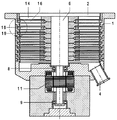
本発明によりほとんどがスペーサ・リング18により形成されるターボ分子ポンプのハウジング1に、吸込開口2およびガス流出開口4が設けられている。ロータ軸6は軸受8および9内に固定され且つモータ11により駆動される。ロータ軸6上にロータ・ディスク14が固定されている。スペーサ・リング18により間隔をなして保持されるステータ・ディスク16はロータ・ディスク14間に装着されている。ロータ・ディスク14およびステータ・ディスク16はそれぞれポンプ作用構造を備え且つそれらの協働によりポンプ効果を発生する。
A suction opening 2 and a gas outflow opening 4 are provided in a housing 1 of a turbomolecular pump, which is mostly formed by
本発明により、スペーサ・リング18は、それらがポンプ・ハウジングの機能を受け持つように組み合わされ且つ結合される。即ち、スペーサ・リング18はステータ・ディスク16の固定および心出しのためにも使用される。
In accordance with the present invention, the
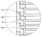
図2に2つのスペーサ・リング18aおよび19aが示され、これらはステータ・ディスク16を固定している。2つのスペーサ・リング18aおよび19aは位置20においてねじ部により相互に固定結合されている。
In FIG. 2, two spacer rings 18a and 19a are shown which secure the
図3はステータ・ディスク16を有する2つのスペーサ・リング18bおよび19bを示し、この場合、スペーサ・リング18bおよび19bはウェブ22および溝23からなるクリップ結合により相互に固定結合されている。
FIG. 3 shows two
図4はステータ・ディスク16を有する2つのスペーサ・リング18cおよび19cを示す。スペーサ・リング18cおよび19cはピン24により相互に固定結合されている。
FIG. 4 shows two
図5にステータ・ディスク16を有する2つのスペーサ・リング18dおよび19dが示されている。ここでは、スペーサ・リング18dおよび19dは位置26におけるはめ合い部を介して圧着により相互に摩擦固定結合されている。
In FIG. 5, two
個々のスペーサ・リング間のシールおよびスペーサ・リングと他の構造部分との間のシールはここには示されていない。これらのシールは、例えばドイツ特許公開第19951954号に示されているようなそれ自身既知の設計により行われてもよい。 Seals between the individual spacer rings and between the spacer rings and other structural parts are not shown here. These seals may be made according to designs known per se, for example as shown in DE-A-199519554.
1 ハウジング
2 吸込開口
4 ガス流出開口
6 ロータ軸
8、9 軸受
11 モータ
14 ロータ・ディスク
16 ステータ・ディスク
18、19、18a、19a、18b、19b、18c、19c、18d、19d スペーサ・リング
20 ねじ部
22 ウェブ
23 溝
24 ピンはめ合い(ピン)
26 はめ合い部
DESCRIPTION OF SYMBOLS 1
26 Fitting part
Claims (6)
スペーサ・リング(18、19、18a、19a、18b、19b、18c、19c、18d、19d)は、それらがそれぞれの隣接リングと固定結合をなすことにより全体としてステータ・ディスクの固定および心出しを行うように形成されていることを特徴とするターボ分子ポンプ。 The stator disks (16) are held at intervals by the spacer rings (18, 19), the rotor disks (14) and the stator disks (16) are alternately arranged one after the other and their cooperation. In a turbomolecular pump comprising said rotor disk (14) and stator disk (16), whose action produces a pumping effect,
The spacer rings (18, 19, 18a, 19a, 18b, 19b, 18c, 19c, 18d, 19d) are fixed and centered as a whole by their fixed connection with their respective adjacent rings. A turbo molecular pump characterized by being configured to perform.
Applications Claiming Priority (1)
| Application Number | Priority Date | Filing Date | Title |
|---|---|---|---|
| DE10331932.8A DE10331932B4 (en) | 2003-07-15 | 2003-07-15 | Turbo molecular pump |
Publications (1)
| Publication Number | Publication Date |
|---|---|
| JP2005036798A true JP2005036798A (en) | 2005-02-10 |
Family
ID=33461927
Family Applications (1)
| Application Number | Title | Priority Date | Filing Date |
|---|---|---|---|
| JP2004164365A Pending JP2005036798A (en) | 2003-07-15 | 2004-06-02 | Turbo molecular pump |
Country Status (4)
| Country | Link |
|---|---|
| US (1) | US7278822B2 (en) |
| EP (1) | EP1498612B1 (en) |
| JP (1) | JP2005036798A (en) |
| DE (1) | DE10331932B4 (en) |
Families Citing this family (11)
| Publication number | Priority date | Publication date | Assignee | Title |
|---|---|---|---|---|
| DE102005045283B4 (en) | 2005-09-22 | 2014-05-15 | Pfeiffer Vacuum Gmbh | Vacuum pumping system |
| DE102006050565A1 (en) * | 2006-10-26 | 2008-04-30 | Pfeiffer Vacuum Gmbh | Stator disk for turbo-molecular pump, has plate at outer ring side, so that plate fulfills spacer ring function, and support ring connected with plate, where plate is turned away from plane, and side is turned outwards in radial direction |
| DE102007048703A1 (en) * | 2007-10-11 | 2009-04-16 | Oerlikon Leybold Vacuum Gmbh | Multi-stage turbomolecular pump pump rotor |
| DE102008004297A1 (en) | 2008-01-15 | 2009-07-16 | Oerlikon Leybold Vacuum Gmbh | Turbo molecular pump |
| JP5115622B2 (en) * | 2008-03-31 | 2013-01-09 | 株式会社島津製作所 | Turbo molecular pump |
| ATE513132T1 (en) * | 2008-07-10 | 2011-07-15 | Grundfos Management As | PUMP UNIT |
| DE102008056352A1 (en) * | 2008-11-07 | 2010-05-12 | Oerlikon Leybold Vacuum Gmbh | vacuum pump rotor |
| DE102008058149A1 (en) * | 2008-11-20 | 2010-05-27 | Oerlikon Leybold Vacuum Gmbh | Turbo-molecular pump, has rotor element arranged in pump housing, and stator rings surrounding rotor element, where rings exhibit attachment piece extending in longitudinal direction such that adjacent stator ring is arranged within piece |
| US8221098B2 (en) * | 2009-03-09 | 2012-07-17 | Honeywell International Inc. | Radial turbomolecular pump with electrostatically levitated rotor |
| GB2498816A (en) | 2012-01-27 | 2013-07-31 | Edwards Ltd | Vacuum pump |
| CN114593075B (en) * | 2022-03-15 | 2023-03-24 | 北京中科科仪股份有限公司 | Molecular pump |
Citations (6)
| Publication number | Priority date | Publication date | Assignee | Title |
|---|---|---|---|---|
| US2610786A (en) * | 1946-06-25 | 1952-09-16 | Gen Electric | Axial flow compressor |
| JPH02131089U (en) * | 1989-03-31 | 1990-10-30 | ||
| JPH04330397A (en) * | 1991-04-30 | 1992-11-18 | Fujitsu Ltd | Turbo molecular pump |
| JPH1162879A (en) * | 1997-08-20 | 1999-03-05 | Mitsubishi Heavy Ind Ltd | Turbo molecular pump |
| JPH11201083A (en) * | 1998-01-09 | 1999-07-27 | Ebara Corp | Turbo-molecular pump |
| JP2001153087A (en) * | 1999-10-28 | 2001-06-05 | Pfeiffer Vacuum Gmbh | Turbo molecular pump |
Family Cites Families (10)
| Publication number | Priority date | Publication date | Assignee | Title |
|---|---|---|---|---|
| US1288360A (en) * | 1916-11-06 | 1918-12-17 | Ludwig W Zaar | Turbine. |
| US3032260A (en) * | 1955-07-12 | 1962-05-01 | Latham Manufactruing Co | Rotary apparatus and method of making the same |
| JPS57212395A (en) * | 1981-06-24 | 1982-12-27 | Hitachi Ltd | Molecular pump |
| DE3402549A1 (en) * | 1984-01-26 | 1985-08-01 | Leybold-Heraeus GmbH, 5000 Köln | Molecular vacuum pump |
| DE3722164C2 (en) * | 1987-07-04 | 1995-04-20 | Balzers Pfeiffer Gmbh | Turbomolecular pump |
| DE3891263T1 (en) * | 1988-02-26 | 1990-03-15 | Nikolaj Michailovic Novikov | TURBOMOLECULAR VACUUM PUMP |
| US6332752B2 (en) * | 1997-06-27 | 2001-12-25 | Ebara Corporation | Turbo-molecular pump |
| DE29717764U1 (en) * | 1997-10-06 | 1997-11-20 | Leybold Vakuum Gmbh | Stator for a turbomolecular vacuum pump |
| DE10010371A1 (en) * | 2000-03-02 | 2001-09-06 | Pfeiffer Vacuum Gmbh | Turbomolecular pump |
| US6503050B2 (en) * | 2000-12-18 | 2003-01-07 | Applied Materials Inc. | Turbo-molecular pump having enhanced pumping capacity |
-
2003
- 2003-07-15 DE DE10331932.8A patent/DE10331932B4/en not_active Expired - Fee Related
-
2004
- 2004-06-02 JP JP2004164365A patent/JP2005036798A/en active Pending
- 2004-06-17 EP EP04014174.9A patent/EP1498612B1/en not_active Not-in-force
- 2004-07-14 US US10/890,730 patent/US7278822B2/en not_active Expired - Fee Related
Patent Citations (6)
| Publication number | Priority date | Publication date | Assignee | Title |
|---|---|---|---|---|
| US2610786A (en) * | 1946-06-25 | 1952-09-16 | Gen Electric | Axial flow compressor |
| JPH02131089U (en) * | 1989-03-31 | 1990-10-30 | ||
| JPH04330397A (en) * | 1991-04-30 | 1992-11-18 | Fujitsu Ltd | Turbo molecular pump |
| JPH1162879A (en) * | 1997-08-20 | 1999-03-05 | Mitsubishi Heavy Ind Ltd | Turbo molecular pump |
| JPH11201083A (en) * | 1998-01-09 | 1999-07-27 | Ebara Corp | Turbo-molecular pump |
| JP2001153087A (en) * | 1999-10-28 | 2001-06-05 | Pfeiffer Vacuum Gmbh | Turbo molecular pump |
Also Published As
| Publication number | Publication date |
|---|---|
| US7278822B2 (en) | 2007-10-09 |
| US20050013710A1 (en) | 2005-01-20 |
| DE10331932A1 (en) | 2005-02-03 |
| EP1498612A2 (en) | 2005-01-19 |
| EP1498612B1 (en) | 2015-07-29 |
| DE10331932B4 (en) | 2017-08-24 |
| EP1498612A3 (en) | 2011-09-14 |
Similar Documents
| Publication | Publication Date | Title |
|---|---|---|
| US9909592B2 (en) | Vacuum pump | |
| JP2011062076A (en) | Brushless motor | |
| CN110431310B (en) | Support structure for a drive shaft of a turbomachine and turbomachine comprising such a support structure | |
| JP2005036798A (en) | Turbo molecular pump | |
| US8390161B2 (en) | Electric motor having a rain guard | |
| US20140072408A1 (en) | Vacuum pump | |
| US8684688B2 (en) | Series-connected fan frame module | |
| JP2011074903A (en) | Turbo-molecular pump | |
| JP2001153087A (en) | Turbo molecular pump | |
| US7517153B2 (en) | Fluid dynamic bearing system | |
| JP2009174448A (en) | Fluid pump | |
| JP2010007516A (en) | Electric oil pump | |
| JPWO2019026340A1 (en) | Vacuum pump | |
| JP2004360698A (en) | Small vacuum pump | |
| JP2006063895A (en) | Centrifugal compressor | |
| RU2633278C1 (en) | Standard housing of centrifugal gas compressor | |
| JP5683544B2 (en) | Vacuum pump | |
| JP2006057487A (en) | Centrifugal compressor | |
| JP2011027049A (en) | Turbo-molecular pump | |
| JP2009236063A (en) | Pump device | |
| JP5172115B2 (en) | Swirl compressor and method of manufacturing vortex compressor | |
| JP6361583B2 (en) | Fuel pump | |
| JP5757082B2 (en) | Electric pump | |
| JP2008240571A (en) | Turbo-molecular pump | |
| JP2005146899A (en) | Axial-flow pump |
Legal Events
| Date | Code | Title | Description |
|---|---|---|---|
| A621 | Written request for application examination |
Free format text: JAPANESE INTERMEDIATE CODE: A621 Effective date: 20070425 |
|
| A131 | Notification of reasons for refusal |
Free format text: JAPANESE INTERMEDIATE CODE: A131 Effective date: 20091104 |
|
| A601 | Written request for extension of time |
Free format text: JAPANESE INTERMEDIATE CODE: A601 Effective date: 20100203 |
|
| A602 | Written permission of extension of time |
Free format text: JAPANESE INTERMEDIATE CODE: A602 Effective date: 20100208 |
|
| A02 | Decision of refusal |
Free format text: JAPANESE INTERMEDIATE CODE: A02 Effective date: 20100510 |